thomas truskaller master thesis data integration into a...
TRANSCRIPT
Thomas Truskaller
Master Thesis
Data Integration into aGene Expression Database
Institute of Biomedical Engineering,University of Technology, Graz, Austria
Inffeldgasse 18, A-8010 GrazHead: Univ.-Prof. Dipl.-Ing. Dr.techn. Gert Pfurtscheller
Supervisor:Dipl.-Ing Gerhard Thallinger
Evaluator:Univ.-Prof. Dipl.-Ing. Dr.techn. Zlatko Trajanoski
Graz, September 2003

Abstract
German
Das Ziel dieser Diplomarbeit war die Untersuchung und Entwicklung einerneuen Form von ”Integrativer Software Entwicklung” fur daten- und web-basierte Anwendungen in der Bioinformatik. Im Besonderen wurde auf dieVereinfachung des Entwicklungsprozesses und Abstraktion durch Software-modellierung basierend auf der Unified Modeling Language (UML) eingegan-gen.
Es wurde der Open Source Code Generator AndroMDA in Bezug aufErweiterbarkeit und Anpassbarkeit seiner Grundfunktionen und Codegener-ierungsvorschriften auf datenbasierte Webanwendungen, wie sie vor allem inder Bioinformatik haufig vorkommen, untersucht.
Es hat sich herausgestellt, dass die Verwendung von geeigneten Werkzeu-gen und Techniken, wie UML CASE Tools, Code Generatoren und MDA,das Umsetzen von generellen Anforderungen an die Software Entwicklungwie z.B. Wartbarkeit, Wiederverwendbarkeit, Robustheit und Konsistenz er-leichtern.
Der Schritt zu ”Generativen Software Enwicklungsmethoden” erfordertAnfangs einen hoheren Einarbeitungs- und Lernaufwand, liefert aber mitFortdauer des Projektes wesentliche Vorteile.
Stichworter: MDA, J2EE, Generative Software Entwicklung, AndroMDA
1

English
The goal of this thesis was to investigate and develop a new form of ”Integra-tive Software Development” for data driven and web based applications in thebioinformatics domain. The simplification of the development process andabstraction with UML based software modelling techniques were the mainpoint of interest.
One of the main tasks was the investigation of the open source code gen-erator AndroMDA in terms of its ability for adoption and extensibility ofthe core functionality and its code generation templates for data driven webbased applications.
Facilitating proper tools and technologies like UML CASE tools, codegenerators and MDA, simplifies the development of software and increasesits general requirements like maintainability, reusability, robustness and con-sistency.
The learning effort when using ”generative” software development meth-ods is higher at the beginning, but this pays off through faster applicationdevelopment and better maintainability.
Keywords: MDA, J2EE, Generative Software Entwicklung, AndroMDA
2

Contents
List Of Figures 6
List Of Tables 7
Glossary 8
1 Introduction 121.1 A Simple Example . . . . . . . . . . . . . . . . . . . . . . . . 121.2 Problem Domain . . . . . . . . . . . . . . . . . . . . . . . . . 13
1.2.1 Biological Data . . . . . . . . . . . . . . . . . . . . . . 131.2.2 Gene Expression and Microarray Data Management . . 13
Central dogma of molecular genetics . . . . . . . . . . 14Gene Expression and Microarray . . . . . . . . . . . . 14
1.2.3 Laboratory Management . . . . . . . . . . . . . . . . . 161.2.4 Enterprise Application . . . . . . . . . . . . . . . . . . 161.2.5 General Software Requirements . . . . . . . . . . . . . 16
2 Objectives 172.1 Project Goals . . . . . . . . . . . . . . . . . . . . . . . . . . . 17
3 Methods 183.1 The OMG’s Key Standards . . . . . . . . . . . . . . . . . . . 18
3.1.1 Model Driven Architecture . . . . . . . . . . . . . . . . 193.1.2 Unified Modelling Language . . . . . . . . . . . . . . . 203.1.3 Meta Objects Facility . . . . . . . . . . . . . . . . . . . 213.1.4 XML Metadata Interchange Format . . . . . . . . . . . 21
3.2 Code Generation . . . . . . . . . . . . . . . . . . . . . . . . . 223.2.1 Types of Code Generators . . . . . . . . . . . . . . . . 233.2.2 UML Based Code Generators . . . . . . . . . . . . . . 24
3.3 AndroMDA . . . . . . . . . . . . . . . . . . . . . . . . . . . . 243.3.1 Modelling in the AndroMDA . . . . . . . . . . . . . . 26
3

3.3.2 Exception Handling in AndroMDA . . . . . . . . . . . 273.3.3 Cartridges . . . . . . . . . . . . . . . . . . . . . . . . . 273.3.4 Velocity Templates . . . . . . . . . . . . . . . . . . . . 293.3.5 Outlets . . . . . . . . . . . . . . . . . . . . . . . . . . . 303.3.6 AndroMDA Ant Task . . . . . . . . . . . . . . . . . . 31
3.4 Enterprise JavaBeans . . . . . . . . . . . . . . . . . . . . . . . 333.4.1 Types of Enterprise Beans . . . . . . . . . . . . . . . . 34
Session Beans . . . . . . . . . . . . . . . . . . . . . . . 34Entity Beans . . . . . . . . . . . . . . . . . . . . . . . 35Message-Driven Beans . . . . . . . . . . . . . . . . . . 36
3.4.2 The Contents of an Enterprise Beans . . . . . . . . . . 363.5 XDoclet . . . . . . . . . . . . . . . . . . . . . . . . . . . . . . 373.6 Struts . . . . . . . . . . . . . . . . . . . . . . . . . . . . . . . 37
3.6.1 Struts Controller Components . . . . . . . . . . . . . . 383.6.2 Struts Model Components . . . . . . . . . . . . . . . . 383.6.3 Struts View Components . . . . . . . . . . . . . . . . . 39
3.7 J2EE Patterns . . . . . . . . . . . . . . . . . . . . . . . . . . . 393.7.1 ValueTreeBuilder . . . . . . . . . . . . . . . . . . . . . 40
Usage . . . . . . . . . . . . . . . . . . . . . . . . . . . 40Include Tree Examples . . . . . . . . . . . . . . . . . . 41
4 Results 434.1 Extended Cartridges . . . . . . . . . . . . . . . . . . . . . . . 444.2 Extended EJB Cartridge . . . . . . . . . . . . . . . . . . . . . 44
4.2.1 Bean-managed Persistence Entities . . . . . . . . . . . 454.2.2 PrimaryKey Generator Factory . . . . . . . . . . . . . 454.2.3 Util Classes . . . . . . . . . . . . . . . . . . . . . . . . 464.2.4 Value Objects . . . . . . . . . . . . . . . . . . . . . . . 474.2.5 Services and Standard Operations for Entities . . . . . 49
4.3 Service Locator and Delegate Patterns . . . . . . . . . . . . . 514.4 Extended Struts Cartridges . . . . . . . . . . . . . . . . . . . 524.5 Project Wizard . . . . . . . . . . . . . . . . . . . . . . . . . . 54
4.5.1 Project Directory Structure . . . . . . . . . . . . . . . 55
5 Discussion 565.1 Pros and Cons for Code Generators . . . . . . . . . . . . . . . 57
5.1.1 MDA Approach . . . . . . . . . . . . . . . . . . . . . . 575.2 AndroMDA is Work in Progress . . . . . . . . . . . . . . . . . 575.3 Cartridge Management and Model Transformations . . . . . . 585.4 AndroMDA in the Bioinformatics Domain . . . . . . . . . . . 59
4

Bibliography 70
5
List of Figures
1.1 The central dogma of genetics. . . . . . . . . . . . . . . . . . . 141.2 Microarray experiment process. . . . . . . . . . . . . . . . . . 15
3.1 The Generative Domain Model. . . . . . . . . . . . . . . . . . 233.2 AndroMDA code generation process [33]. . . . . . . . . . . . . 253.3 Participants in the development process with AndroMDA [33]. 263.4 Exception handling in the default cartridges of AndroMDA [3]. 283.5 J2EE architecture in terms of its containers and APIs [12]. . . 343.6 Struts controller mechanism. . . . . . . . . . . . . . . . . . . . 39
4.1 Example for bean-managed persistence entities. . . . . . . . . 464.2 Example for value objects. . . . . . . . . . . . . . . . . . . . . 48
6

List of Tables
1.1 General Software Requirements [32]. . . . . . . . . . . . . . . 16
3.1 UML diagram types . . . . . . . . . . . . . . . . . . . . . . . 203.2 Typical OMG Metadata Architecture . . . . . . . . . . . . . . 223.3 Stereotypes in AndroMDA. . . . . . . . . . . . . . . . . . . . . 273.4 Generated artefacts in EJB and Hibernate cartridges. . . . . . 293.5 Objects which AndroMDA passes to the Velocity templates [2]. 303.6 Types of Enterprise Beans. . . . . . . . . . . . . . . . . . . . . 34
4.1 Validator tags example for an attribute of an entity. . . . . . 53
5.1 The XML elements used in the andromda-cartridge.xml file[2]. . . . . . . . . . . . . . . . . . . . . . . . . . . . . . . . . . 60
5.2 Attributes of the <template> tag in the andromda-cartridge.xmlfile [2]. . . . . . . . . . . . . . . . . . . . . . . . . . . . . . . . 61
5.3 Attributes of the AndroMDA Ant Task [2]. . . . . . . . . . . . 625.4 Ant tasks for the build.xml file in the default project. . . . . 635.5 Default project directory structure. . . . . . . . . . . . . . . . 635.6 Stereotypes for the extended cartridges. . . . . . . . . . . . . . 645.7 Tagged values for the extended cartridges. . . . . . . . . . . . 66
7

Glossary
CASE tools Computer Aided Software Engineering tools for modelling soft-ware systems based on the UML language.
CIM A computation independent model in MDA is a view of a system fromthe computation independent viewpoint. A CIM does not show detailsof the structure of systems. A CIM is sometimes called a domain modeland a vocabulary that is familiar to the practitioners of the domain inquestion is used in its specification.
CORBA CORBA is the acronym for Common Object Request Broker Ar-chitecture, OMGs open, vendor-independent architecture and infras-tructure that computer applications can use to work together over net-works.
CRUD The acronym for create, read, update and delete.
DNA Deoxyribonucleic acid (DNA) is a double-stranded helix of nucleotideswhich carries the genetic information of a cell.
DTD Document Type Definition. An optional part of an XML documentwhich specifies constraints on the valid tags and tag sequences that canbe in the XML document.
EJB An Enterprise Java Bean is a server-side component of the J2EE plat-form that encapsulates the business logic of an application.
framework APIs that are intended to simplify the design and coding pro-cess.
Hibernate Hibernate is a object/relational persistence and query servicefor Java.
IDL Interface Definition Language is the OMGs standard language for defin-ing the interfaces for all CORBA objects.
8

Java Object oriented, high-level programming language and platform devel-oped from Sun.
JDBC Java database connectivity. This set of application programminginterfaces (APIs) provides a standard mechanism to allow Java appli-cations access a database.
JDO Java Data Objects is a specification to enable transparent persistenceof Java objects.
JNDI Java Naming and Directory Interface specification enables Java platform-based applications to access multiple naming and directory services.
JSF JavaServer Faces, a proposal to define an architecture and APIs thatsimplify the process of building J2EE web tier applications.
JSP Java Server Pages is a language similar to Microsoft’s ASP for creatingdynamic web pages. Sun has created a language specification. WithJSP, a single source text file is created containing both HTML (orXML) tags and Java-like scriptlets. The JSP-aware web server creates,compiles and runs a servlet from the source text.
JSTL JavaServer Pages Standard Tag Library. A standard tag library thatencapsulates core features common to many JSP pages as simple tags.JSTL contains support for common, structural tasks. Support includesiteration and conditionals, tags for manipulating XML documents, in-ternationalization tags, and SQL tags.
J2EE Java 2 Platform, Enterprise Edition is a set of coordinated speci-fications and practices that together enable solutions for developing,deploying, and managing multi-tier server-centric applications.
MARS Microarray Analysis and Retrieval System is used for storing, pro-cessing and organising microarray data based on Java technologies(EJB, JSP, Servlets etc.) and Open Source frameworks (Struts etc.).It is developed by the TU-Graz Bioinformatics Group.
MDA Model Driven Architecture is an OMG standard with the well-knownand long established idea of separating the specification of the operationof a system from the details of the way that system uses the capabilitiesof its platform.
MGED The Microarray Gene Expression Data Society is an internationalorganisation of biologists, computer scientists, and data analysts that
9

aims to facilitate the sharing of microarray data generated by functionalgenomics and proteomics experiments.
Metadata A general term for data that in some sense describes information(data).
Microarray Sometimes called a gene chip or a DNA chip. Microarraysconsist of large numbers of molecules (often, but not always, DNA)distributed in a grid in a very small space. Microarrays permit scientiststo study gene expression by providing a snapshot of all the genes thatare active in a cell at a particular time.
Model A model is generally usually used to denote a description of some-thing, typically something in the real world.
MOF The Meta-Object Facility specification defines an abstract languageand a framework for specifying, constructing and managing technologyneutral metamodels.
MVC Model / View / Controller. A user-interface design pattern pioneeredby Smalltalk and later co-opted by Java et. al. The Model is typicallya data-bearing business object, the View is an object capable of pre-senting some form of visual output from the Model, and the Controlleris responsible for processing user events.
NCBI The National Center for Biotechnology Information
.NET At its core, Microsoft .NET is about integrating services. To make useof .NET is in essence to connect information using the Microsoft .NETfamily of software technologies. The technologies break down into threechunks, the .NET Framework, .NET Web Services, and ASP.NET.
OMG The Object Management Group is an open membership, not-for-profit consortium that produces and maintains computer industry spec-ifications for interoperable enterprise applications.
ORM tool Object Relational Mapping tool, storing objects in relationaldatabases.
PIM A Platform Independent Model is a view of a system from the platformindependent viewpoint. A PIM exhibits a specified degree of platformindependence so as to be suitable for use with a number of differentplatforms of similar type.
10

Platform A Platform in MDA is a set of subsystems and technologies thatprovide a coherent set of functionality through interfaces and specifiedusage patterns, which any application supported by that platform canuse without concern for the details of how the functionality providedby the platform is implemented.
PSM A Platform Specific Model in MDA is a view of a system from theplatform specific viewpoint. A PSM combines the specifications in thePIM with the details that specify how that system uses a particulartype of platform.
RDBMS Relational database and management system is a collection ofprograms that enable multiple users within a system to store, modify,and extract information from a database based on relational tables.
RNA Ribonucleic acid. One of the two types of nucleic acids found inall cells. The other is deoxyribonucleic acid (DNA). RNA transmitsgenetic information from DNA to proteins produced by the cell. Threetypes of RNA include: messenger RNA (mRNA), transfer RNA (tRNA)and ribosomal RNA (rRNA).
UML OMGs Unified Modeling Language is a language for specifying, con-structing, visualizing, and documenting the artifacts of a software-intensive system.
Web Services Web services are units of application logic with publishedAPI’s that provide data and services to other applications. They lever-age industry-standard communication formats such as XML and SOAP.Web services can be called across platforms and operating systems, andwithout regard to the underlying programming language.
XMI The XMI Specification defines technology mappings from MOF meta-models to XML Document Type Definitions (DTDs) and XML docu-ments.
XML Extensible Markup Language is an open standard of the World WideWeb Consortium (W3C) designed as a data format for structured doc-ument interchange on the web.
XSLT Extensible Style Sheet Language Transformation is a W3C-specifiedlanguage for transforming XML documents into other XML documents.
11

Chapter 1
Introduction
This chapter highlights the problems when handling large biological data setsfrom the programmers point of view. A simple example will show the dif-ficulties in manipulating new kind of data and adopting existing databases.Projects often start with a few and simple requirements, but likely evolveinto big heterogenic and complex enterprise applications.
1.1 A Simple Example
At the Institute of Biomedical Engineering - Graz University of Technologythe Bioinformatics Group [5] is working on microarray experiments. Thegroup consists of biologists, chemists and software developers. For storingthe microarray data a database system called MARS (Microarray Analysisand Retrieval System) was developed based on Java [11] technology.
By and by the additional requirements emerged and the existing codehad to be reverse engineered. This is a very tedious and error prone work forprogrammers because they have to make changes on existing codes and findout if these modifications didn’t corrupt the application. New programmersjoining the team have to learn the architecture design and coding standards.
The existing MARS system provides basic functionality for storing mi-croarray specific data. Requirement changes should cause minor coding ef-forts and new modules should be added in a ”Plugin” manner.
Potential additional requirements for the MARS system could include:
• new user management
12

• integration into clinical workflows
• analysis tools for quality control
• integration of laboratory management system
• integration of metabolic data
The work with microarrays is still research work and it is very likely thatthere will be changes in the process. New technologies and methods will comeup and improve appearance of the experiments. A key role for reproducibleand reliable results is a broad quality assessment.
1.2 Problem Domain
1.2.1 Biological Data
The human genome consists of about 3 billion bases where each can be A,G, T or C. Storing this information would require about 3000 Mega Byte ofdisc space. Scientists estimate a number of about 35000 - 45000 genes in thehuman genome [28].
Simply spoken: Each gene is a sequence of bases which is the codinginstruction for a type of protein. The proteins are key players in the func-tionality and structure of organisms. The numbers of genes, proteins andother microbiological components show the complexity when dealing withbiological data. Without computer systems it would be nearly impossible toprocess all the biological data flood.
Bioinformatics is an inherently integrative discipline, requiring access todata from a wide range of sources [27]. ”The NCBI Handbook” [22] gives aninsight into the basic data-storages, -flow, -processing, -querying and -linkingtools on the biological domain and is recommend for further readings.
1.2.2 Gene Expression and Microarray Data Manage-ment
Microarray technology was introduced in the year 1995 by Schena et al.[34]. To understand microarray experiments technology one have to under-stand the central dogma of molecular genetics. It describes the way from
13

deoxyribonucleic acid (DNA) to messenger ribonucleic acid (mRNA) andfrom mRNA to proteins shown in figure 1.1.
Central dogma of molecular genetics
DNA is a double-stranded helix of nucleotides which carries the genetic in-formation of a cell. It encodes the information for the proteins and is ableto duplicate itself to be passed on to the next generation of cells (replication).
mRNA (messenger RNA) is the mediating template between DNA andproteins. The information from a particular gene is transferred from a strandof DNA by the construction of a complementary strand of RNA through aprocess known as transcription. Three nucleotide segments of RNA, calledtransfer RNA (tRNA), which are attached to specific amino acids, match upwith the template strand of mRNA to order the amino acids correctly. Theseamino acids are then bonded together to form a protein. This process, calledtranslation occurs in the ribosome, which is composed of proteins and thethird kind of RNA, ribosomal RNA (rRNA). The so called ”central dogmaof molecular genetics” was introduced by Francis Crick 1970 [29].
ProteinDNA mRNA
Replication
Transcription
Translation
ReverseTranscription
Figure 1.1: The central dogma of genetics.
Gene Expression and Microarray
Gene expression is the activity of a gene in a cell at a certain time point. Ifthe gene is active then the corresponding mRNA is transcribed and the pro-tein translated. In microarray experiments the concentration of the mRNAin the cell is used for measuring the activity of a gene. A microarray ex-periment can show the gene expression of several thousands of genes (up to30000 and more genes) at a certain time point on a single glass slide.
14

Figure 1.2: Microarray experiment process.
Figure 1.2 shows the generation of a microarray experiment in a simpli-fied form. The DNA microarray experiment process can be divided into twobranches: one preparing the DNA chip (microarray) using the chosen targetDNAs and the other preparing a hybridization solution containing a mix-ture of fluorescently labelled cDNAs. The branches merge when the chipsare hybridised, where the probes are bound to the samples on the carrier.Bound cDNA is detected using laser technology and the data are stored ona computer system where they can be used for further analysis.
With microarray technology one can obtain a snapshot of the activity fornearly all genes in a cell for a certain time point. It is possible to process thedata with computational methods and analyse the whole bunch of genes forspecific profiles without focusing on one specific gene.
Standards for microarray experiments are administered at the MGED [26]site. Storing microarray data can be done in various techniques: in XML files,Relational Database Management Systems (RDBMS) databases and more.The web resource [1] gives a listing of microarray databases on the web.
15

1.2.3 Laboratory Management
The work with microarray experiments is tightly coupled to laboratory work.Using a quality management (QM) system is an essential requirement forreliable and usable data. Additional QM technologies will emerge whichhave to be integrated into the existing MARS system. To reduce coding andprogramming work an efficient way of programming and data integration hasto be developed.
1.2.4 Enterprise Application
The demand for integration of biological data and experiments with clinicalresearch and production is increasing. Applications are facing an increase ininformation and data to be managed. The steady expansion of applicationsis not exclusively limited on biological domain although it is one of the mostgrowing ones. The solutions developed during this work are applicable forany kind of software projects.
1.2.5 General Software Requirements
Software development is a mature engineering discipline and general require-ments to be followed were found out long times ago. High quality softwarehas to fulfill the premises listed in table 1.1:
Requirements Meaning
Robustness code must have a defined behavior under defined circumstancesConsistent code code has to be consistent and follow predefined Style GuidelinesSimple code code should follow the Keep It Small and Simple (KISS) philosophyModularity use interface definitions for separationFlexibility design reusable components applicable for similar requirementsPortability important is the choice of the Integrated Development Environment
(IDE) and programming languageIntuitive code code must be readable like a book (use representative names for
classes, variables and methods)Performance separate subjective and objective performanceMaintainability given when all the other requirements are fulfilledExtensibility given when all the other requirements are fulfilled
Table 1.1: General Software Requirements [32].
16

Chapter 2
Objectives
The goals for the integration framework were derived from the collected expe-rience on several software projects implemented on the Bioinformatics GroupGraz [5]. Most applications developed are multi layered, web based and writ-ten in the Java programming language.
2.1 Project Goals
The following project goals were defined before starting working on the im-plementation framework.
• To implement a framework for easy integration of data into a geneexpression database. Since the type of data collected during the processof biological experiments and analysis is not known, a dynamic andflexible solution for adding the different kinds of data should be built.This data could be metabolic data, gel images for quality control orother biological experiments.
• To find a mechanism for easier and faster programming of data driven,multilayered and web based applications, where also general softwarerequirements are taken into account.
17

Chapter 3
Methods
This chapter will give a brief introduction of the technologies used in theintegration framework, references and links for further reading are includedin each topic.
3.1 The OMG’s Key Standards
The Object Management Group (OMG) [18] was formed to help reduce com-plexity, lower costs, and speed up the introduction of new software applica-tions. The OMG accomplishes this goal through the introduction of theModel Driven Architecture (MDA) architectural framework and its detailedspecifications. These specifications should lead the industry towards inter-operable, reusable, portable software components and data models based onstandard models [30].
OMG has adopted a number of technologies, which combined enable themodel-driven approach. These include Unified Modelling Language (UML),XML Metadata Interchange (XMI) Format, Meta Objects Facility (MOF),specific MOF models as well as UML profiles. All OMG specifications areavailable on the web [6].
18

3.1.1 Model Driven Architecture
The MDA is a new way of defining specifications and developing applications,based on a platform-independent model (PIM)1. A complete MDA specifica-tion consists of a distinct platform-independent UML base model, plus oneor more platform-specific models (PSM) and interface definition sets, eachdescribing how the base model is implemented on a specific middleware plat-form.
The MDA aims to separate business or application logic from the un-derlying platform technology. Platform-independent applications built usingMDA and associated standards can be implemented using a wide range ofopen and proprietary platforms including Common Object Request BrokerArchitecture (CORBA), J2EE, .NET, Web Services or other web-based plat-forms.
It is not necessary to repeat the process of modelling an application orsystem’s functionality and behavior each time a new technology (e.g. .NET,EJB 2.0) comes along. With MDA function and behavior are modeled onlyonce. Mapping from a PIM through a PSM to the supported MDA platformswill be implemented by tools, easing the task of supporting new or differenttechnologies.
The MDA provides an approach for and enables tools to be provided for:
• specifying a system independently of the platform that supports it
• specifying platforms
• choosing a particular platform for the system
• transforming the system specification into one for a particular platform
The three primary goals of MDA are portability, interoperability andreusability through architectural separation of concerns. MDA separates im-plementation details from business functions.
1A platform in general is a set of subsystems/technologies that provide a coherentset of functionality through interfaces and specified usage patterns. Any subsystem thatdepends on the platform can use these technologies without concern for the details of howthe functionality provided by the platform is implemented.
19

3.1.2 Unified Modelling Language
Modelling is the design of software applications before coding and an essentialpart of large software projects, helpful for medium and even small projectsas well [20].
The OMG’s UML [19] specification defines a graphical language to specify,visualize, and document models of software systems, including their struc-ture and design. (UML can be used for business modelling and modellingof other non-software systems too.) Using any of the large number of UML-based tools on the market2, future applications requirements can be analysedand designed representing the results using UML’s standard diagram types.Models used with MDA can be expressed using the UML language.
The UML Specification includes the following:
• a formal definition of the UML metamodel; that is, the abstract lan-guage for specifying UML models
• a (non-normative) graphic notation for expressing UML models
• a set of CORBA Interface Definition Language (IDL) interfaces forrepresenting and managing UML models
• a XML Metadata Interchange (XMI) format for UML model inter-change.
The graphic notation defines twelve types of diagrams with its model el-ements, divided into three categories shown in table 3.1:
Diagram Category Diagram Name
Structural Class Diagram, Object Diagram,Component Diagram, Deployment Diagram
Behavior Use Case Diagram, Sequence Diagram,Activity Diagram, Collaboration Diagram,Statechart Diagram
Model Management Packages, Subsystems, Models
Table 3.1: UML diagram types
2A list of UML tools can be found on http://www.jeckle.de/umltools.htm (fromSeptember 10th, 2003)
20

3.1.3 Meta Objects Facility
The Meta-Object Facility (MOF) specification defines an abstract languageand a framework for specifying, constructing and managing technology neu-tral metamodels. A metamodel is in effect an abstract language for somekind of metadata. Examples include the metamodels for UML, CommonWarehouse Meta-Model (CWM) and the MOF itself as well as others in var-ious OMG specifications in progress.
In addition, the MOF defines a framework for implementing repositoriesthat hold metadata (e.g. models) described by the metamodels.
The MOF specification includes the following:
• a formal definition of the MOF meta-metamodel; that is, the abstractlanguage for specifying MOF metamodels
• a mapping from arbitrary MOF metamodels to CORBA IDL that pro-duces IDL interfaces for managing any kind of metadata
• a set of ”reflective” CORBA IDL interfaces for managing metadataindependent of the metamodel
• a set of CORBA IDL interfaces for representing and managing MOFmetamodels
• an XMI format for MOF metamodel interchange
3.1.4 XML Metadata Interchange Format
The objective of XML Metadata Interchange (XMI) is to allow the exchangeof objects from the OMG’s Object Analysis and Design Facility. It is basedon the XML (Extensible Markup Language) standard.
The XMI Specification defines technology mappings from MOF meta-models to XML Document Type Definitions (DTDs) and XML documents.These mappings can be used to define an interchange format for metadataconforming to a given MOF metamodel.
Table 3.2 shows the four layered architecture of the OMG metadata ar-chitecture:
21

Meta-level MOF term Example DTD/XMI
M3 meta-metamodel The ”MOF Model” (anabstract syntax fordefining metamodels)
MOF DTD
M2 meta-metadata,metamodel
UML Metamodel,CWMI Metamodel, etc.
UML DTD
M1 metadata, model UML Models, Ware-house Schemas, etc.
UML models asXMI documents
M0 data modeled systems, Ware-house databases, etc.
Table 3.2: The MOF metadata framework is typically depicted as a four layerarchitecture
There are 2 versions of the XMI specification, as follows:
• Version 1.2: Defines the main purpose of XMI which is to enableeasy interchange of metadata between modelling tools (based on theOMG-UML) and metadata repositories (OMG-MOF) in distributedheterogeneous environments.
• Version 2.0: Defines XMI Version 2 which leverages new features inXML Schemas that are not available in DTDs.
The main difference from version 1.2 to 2.0 is the use of XML Schemas,a more comprehensive form of XML document validation, instead of XMLDTDs.
3.2 Code Generation
A generator is a program that takes a higher level specification, describing theproblem domain, and configuration (transformation) information, to producea specific solution (implementation). The generative domain model [31] putsthis into a schema shown in figure 3.1.
The automation of software production speeds up software developmentand reduces development costs, while also improving quality, reducing errors,requiring less maintenance efforts and consequently leading to lower mainte-nance costs.
22

Configuration Information:- defaults- dependencies- restrictions- optimizations- production plan
Problem space:- attributes- domain specific notion
Solution space:- elementary components- can be combined in multiple
ways- not redundant- architecture of software system
family
Figure 3.1: The Generative Domain Model consists of the Problem Space,the Configuration Information and the Solution Space [35].
3.2.1 Types of Code Generators
So called ”Closed” generators on one side provide fixed - but optimised - so-lutions, without the possibility of modification and adoption in the problemand configuration space of the generative domain model. The specification(problem domain) is defined in a proprietary, textual or graphical language.Examples for this kind of generators are CORBA-IDL and EJB compiler.”Open” generators on the other side have no restrictions in the generatedcode and its structure. The developers are provided with the basic function-ality of code generation with the possibility to define the meta model andconfiguration (transformation) rules for their requirements. Examples areTemplate-Based Systems and Frame Processors as well as Abstract SyntaxTree based (AST) Application Programming Interface (API) [35]. There aresystems comprising both types mentioned above. Most of the time they havea fixed modelling language and free definable generation rules [36].
Code generators on the market have varying characteristics in the wayhow to adopt the generator and the generation rules for the needs of thedevelopers. Generation rules (often called ”cartridges”) define the transfor-mation from the domain model to the implementation code.
Cartridges hold information about the specific technical solution andshould have a hierarchical structure for reusability. Hand written cartridgesare difficult to maintain, they also lack a way of visualization and reusabil-ity. A better solution is to describe the generation rules in a formal modeland generate the cartridges (generation of generation rules). In this waythe benefits of the MDA (Model Driven Architecture) can be ported to thedevelopment of code generators. ArcStyler is a model based code generatorprovided by Interactive Objects3. Its code generation rules are hierarchical
3http://www.io-software.com/ (from September 10th, 2003)
23

structured and itself generated from UML models [25] for easier maintenance.
3.2.2 UML Based Code Generators
UML (see sec. 3.1.2) provides a graphical language for describing software.With XMI (see sec. 3.1.4) you can serialize and transfer the UML modelsamong different UML tools. An UML based code generator ideally reads theUML model from a model repository (XMI file, direct from memory etc.)and generates platform specific code out of it. Many CASE tools providecode generators which are more or less ”Closed” generators. Very often theyhave proprietary features and only interact with models of one CASE toolinstead of the XMI standard. One UML based code generator is AndroMDA,which will be described in more detail in section 3.3.
3.3 AndroMDA
The Open Source project AndroMDA [2] is a template based code generatorframework written in Java - it takes an UML model from a CASE-tool andgenerates custom components based on Velocity [23] templates. The projectprovides tools for a model based and generative software development fol-lowing the MDA-paradigm. The goal of AndroMDA is to develop a toolboxfor complete MDA based development.
Figure 3.2 gives an overview of the development cycle in AndroMDA. Onthe input side it takes an UML model and builds a corresponding metamodelusing the Metadata Repository (MDR), an Open Source project of ”Netbeans”[17]. Currently only the MOF/UML 1.4 in MOF/XMI 1.2 is supported.
The instantiated objects of the model are sent to Velocity, an Open Sourcescripting engine which can generate any text document from the model de-pending on the generation rules (cartridges).
AndroMDA evolved from the UML2EJB project and cartridges for EJB(Enterprise Java Bean) components exist. Cartridges for the O/R mappingtool Hibernate [9] as an alternative persistence technology and cartridges forthe Struts [21] framework for web applications were developed in the lastperiod of the project. It is up to the developers to write their own cartridgesor modify the existing ones. There might be cartridges for .NET, CORBA
24

Figure 3.2: AndroMDA code generation process [33].
and any other technology as well.
The EJB and Hibernate cartridges generate java source code tagged withadditional information readable for the XDoclet [24] code generator frame-work. XDoclet processes the source code, generates interface and deploymentdescriptors and completes the code generation process. An introduction toXDoclet will be given in section 3.5.
Figure 3.3 shows the roles participating in the development process withAndroMDA. The architect is responsible for architecture- and template de-sign and must be a specialist on the implementation technology. The domainmodeler is a specialist for the business domain and models its processes ina PIM model. The developer adds supplementary information to the model(i.e. tagged values) and provides the model for the code generator. After thecode generation the developer has to code business logic into the implemen-tation classes. The deploy process is supported by Ant build tasks. At theend of the process the developer has to test the components. An introductioninto AndroMDA and its main features can be found in [33].
25

Figure 3.3: Participants in the development process with AndroMDA [33].
3.3.1 Modelling in the AndroMDA
AndroMDA is a tool with a medium amount of intelligence built into it. Sucha tool always has to rely upon clearly defined preconditions. In the case ofAndroMDA these preconditions are modelling conventions. A UML modelfor use with AndroMDA cannot be structured arbitrarily, it has to adhere toa certain structure that can be interpreted by AndroMDA cartridges.
Not too many constraints should be imposed on the modeler - after all, amodel should represent the conceptual reality of the customer’s requirementsand the structure of the application domain.
AndroMDA uses stereotypes4 on different kinds of model elements, eachwith its own special meaning or intention shown in table 3.3:
4UML Stereotypes are a kind of ”labels” that you attach to modelling elements toclassify them.
26

Stereotype Model element Meaning
Entity class business object or domain objectthat knows much and does little
Service class dynamic element or activity thatdoes something to the entities
PrimaryKey attribute of an entityclass
mark attribute as primary key sothat the entity can be found in adatabase system
FinderMethod operation of an entityclass
associate this method with adatabase query to find this entity
EntityRef
ServiceRef
dependency betweenclass A and class B
make A depend on B when a car-tridge needs this info
Exception dependency betweenclass A and class B
make B an exception thrown by allbusiness methods of A
WebAction class Web Action (controller) class
WebForm class Web form (model) class
WebJSP class JavaServer (view) Page
Table 3.3: Stereotypes in AndroMDA.
3.3.2 Exception Handling in AndroMDA
UML dependencies with the stereotype <<Exception>> model the excep-tion handling in AndroMDAs default cartridges. They point from<<Entity>> or <<Service>> components to an exception classes. Thiswill cause AndroMDA to generate ”throws” clauses which contain this excep-tion class in the methods of the components. AndroMDA does not generateexception classes, they have to be written manually. See figure 3.4 for anexample.
3.3.3 Cartridges
Cartridges were introduced to separate the development of the core generatorframework and the code generation templates. A cartridge can be seen as anblueprint of a specific technology (e.g. EJBs, .NET, CORBA, Struts, Java,C# and many more). They plug into the AndroMDA core and drive code
27

<<Service>>
AdminService
<<Entity>>
Administrator
AdminsException
<<EntityRef>>
<<Exception>>
<<EntityRef>>
<<Exception>>
Figure 3.4: Exception handling in the default cartridges of AndroMDA [3].
generation based on templates.
Cartridges in AndroMDA are jar files, zip files or directories. They con-tain the Velocity templates, Java classes (needed by the specific cartridge)and a META-INF subdirectory containing a descriptor file named andromda-
cartridge.xml. AndroMDA searches for the andromda-cartridge.xml fileon the ”classpath” to locate the available cartridges automatically. The coreuses this descriptor to find out the capabilities of a cartridge: the supportedstereotypes, the outlets (see sec. 3.3.5) and the Velocity templates. Anandromda-cartridge.xml file could look like listing 3.1:
<cartridge name="ejb"><property name=" persistence " value="ejb" /><property ... / ><stereotype name=" Entity " /><stereotype ... / ><outlet name="entity -beans" /><outlet ... / ><template
stereotype =" Entity"sheet=" templates/EntityBean.vsl"outputPattern ="{0}/{1} Bean.java"outlet ="entity -beans"overWrite ="true" />
<template ... / ></cartridge >
Listing 3.1: AndroMDA cartridge definition example.
28

Table 5.1 in the appendix shows the XML elements with description usedin the andromda-cartridge.xml. The attributes of the <template> tag areshown in table 5.2 in the appendix.
AndroMDA delivers cartridges for EJBs, Hibernate and Struts. The EJBcartridge generates Session Beans for services and Entity Beans for persis-tence. The Hibernate cartridge generates plain old java objects and utilisesthe OR mapping framework Hibernate for persistence. Table 3.4 lists theartefacts5 generated by the EJB and Hibernate cartridges.
The struts cartridge generates Struts-actions, -forms, JSPs and the struts-config.xml file. Modelling the struts framework in a class diagram is rathertedious, therefore another solution facilitating activity graphs in the UMLmodel is under development6.
Stereotype EJB Hibernate
Entity Entity Bean Java object with persistencesupport plus factory class
Service Session Bean Java object
PrimaryKey marks attribute as ”PK” marks attribute as ”id”
FinderMethod finder method on home inter-face
finder method in associatedfactory
EntityRef ejbref from ABean to BBeanand getBLocalHome() inABean
nothing
ServiceRef ejbref from ABean to BBean getBHome() in ABean
Exception ”throws B” in all business methods of A
Table 3.4: Generated artefacts in EJB and Hibernate cartridges.
3.3.4 Velocity Templates
Velocity is a Java-based template engine. It permits anyone to use the simpleyet powerful template language to reference Java defined objects [23].
5In this term an artefact is a result or product of a code generation process.6Announced on the AndroMDA mailing list
29

AndroMDA uses velocity templates for the code generation process. Inthe andromda-cartridge.xml the mapping from stereotype to Velocity tem-plate is defined. The outlet attribute defines the destination for the generatedsource.
The cartridge in listing 3.1 would cause AndroMDA to invoke the velocitytemplate EntityBean.vsl for each class with the stereotype <<Entity>>in the UML model. AndroMDA passes the objects in table 3.5 to the tem-plates. Through the scripting variables the template developer has accessto the methods defined in the Java objects. See the Velocity home page forfurther readings [23].
Object name Description More info
$model Contains the model that wasbuilt in the case tool, in theform a UML v1.4 model.
Model
$class Provides a reference to theUML model element for whichcode should be generated.
In general that object will beof type PModelElement and inthe case of a class it will be oftype PClassifier
$transform Helper object that can trans-form model objects into aprintable form that can beused easily from a VTL script.
SimpleOOHelper
$str Helper object that can per-form string formatting.
StringUtilsHelper
$date The current date. java.util.Date
Table 3.5: Objects which AndroMDA passes to the Velocity templates [2].
The template in listing 3.2 just prints the name and the fully qualifiedname of the class into the output file shown in listing 3.3.
3.3.5 Outlets
Outlets provide a logical name used in the cartridges and the Ant build pro-cess. The cartridges define an outlet and map templates to outlets (see table
30

Simple Velocity template!-------------------------class name = ${class.name}fqn = $transform.getFullyQualifiedName($class)
Listing 3.2: Simple Velocity template example.
Simple Velocity template!-------------------------class name = EntityXfqn = some.package.EntityX
Listing 3.3: Output of the example in 3.2.
5.2). The Ant build.xml file maps the outlets to a physical directory. Dur-ing the generation process the code will be stored in that directory. Thelisting 3.4 is a snip of a build.xml file using the cartridge definition shownin listing 3.1.
3.3.6 AndroMDA Ant Task
Currently AndroMDA is implemented as a custom task for the build toolAnt [4]. Ant is a Java-based build tool and therefor platform independent.It was invented to simplify the build process without the huffiness of the”GNU Make” tool.
Ant tasks perform the actual work. Besides the core tasks for low levelwork like copying, creating directories, zipping etc., optional tasks for morecomplex work exist. Developers also have the possibility to define their owntasks by extending the Ant framework.
<andromda ... >...<outlet cartridge ="ejb"
outlet ="entity -beans"dir="/ home/myproject/src/java/ejb/gen/" />
...</andromda >
Listing 3.4: Outlet definition example in the AndroMDA ant task.
31

The whole build process is based on an XML file (often named build.xml).There the tasks are defined based on a hierarchical structure. AndroMDAprovides a custom task for executing the generator. The properties are listedin table 5.3 in the appendix.
Listing 3.5 shows a snip of an AndroMDA Ant task in a build.xml file:
<project name="${project.name }" default ="jars">...<unzip src=" CarRentalSystem15.zargo"
dest="${build.dir}/ unzipped"/>
<andromda basedir ="${build.dir}/ unzipped"includes =" CarRentalSystem15.xmi"lastModifiedCheck =" false"typeMappings ="./ src/xml/TypeMapping.xml">
<outlet cartridge ="ejb"outlet ="entity -beans"dir="/ home/myproject/src/java/ejb/gen/" />
...</andromda >...</project >
Listing 3.5: AndroMDA ant task example.
The <andromda> task supports nested <outlet> tags to customize themappings for output directories where the generate source code will be placed.
It also supports a nested <repository> tag to write extensions to An-droMDA. AndroMDA by default reads models from XMI files. If wanted,AndroMDA could read the model from another format, or source type. Thistag would be useful for implementing that sort of extension.
The attribute transformClassname specifies the name of the java classthat implements the script helper that the Velocity code templates access as$transform. The attribute classname specifies the name of the java classthat implements AndroMDA’s meta data repository. One way to write anown meta data repository is by extending the class MDRepositoryFacade.
32

3.4 Enterprise JavaBeans
Enterprise JavaBean [7] is the server-side business layer component speci-fication for the J2EE (Java 2 Enterprise Edition) platform. EJBs enablesrapid and simplified development of distributed, transactional, secure andportable Java applications. The developers of EJBs do not have to designand program transactions, security and remote accessability for their ownbecause this is done by the container providers, who are specialists on thatarea. Instead the component developers use declarative methods, facilitatingdeployment descriptors to define, how the container should act for the spe-cific components.
Enterprise beans are the J2EE components that implement EnterpriseJavaBeans (EJB) technology. Enterprise beans run in the EJB container,a runtime environment within the J2EE server, see figure 3.5. The J2EEspecification defines several APIs which a container has to provide to itscomponents.
There are 30 and more J2EE implementations available on the market7.AndroMDAs cartridges currently generate components and descriptors forthe Open Source application server JBoss [13].
If an application has any of the following requirements the use of enter-prise beans might be considered:
• The application must be scalable. To accommodate a growing numberof users, it might be necessary to distribute an application’s componentsacross multiple machines might be needed. Not only can the enterprisebeans of an application run on different machines, but their locationwill remain transparent to the clients.
• Transactions are required to ensure data integrity. Enterprise beanssupport transactions, the mechanisms that manage the concurrent ac-cess of shared objects.
• The application will have a variety of clients. With just a few lines ofcode, remote clients can easily locate enterprise beans. These clientscan be thin, various, and numerous8.
7A listing of J2EE application server can be found underhttp://www.theserverside.com/reviews/matrix.jsp (from September 10th, 2003)
8For instance web browsers, handhelds, native java applications, applets etc.
33

Database
EJBJSP
Client
J2SE J2SE
J2SE
J2SE
SSLHTTP
Applet
EJBWeb
Application
HTTPSSL
Container
Applet
Servlet
Container Container
JAX
P
JMS
JAA
S
JAX
P
JDB
C
Conn.
JDB
C
JTA
JAA
S
JMS
Conn.
JDB
C
JAX
P
JTA
JAA
S
JMS
JAF
JAFClientContainer
Application
RMI / IIOP
Figure 3.5: J2EE architecture in terms of its containers and APIs [12].
3.4.1 Types of Enterprise Beans
Enterprise Beans are divided in three categories, each for certain purposes.
Enterprise Bean Type Purpose
Session Performs a task for a client
Entity Represents a business entity object that existsin persistent storage
Message-Driven Acts as a listener for the Java Message ServiceAPI, processing messages asynchronously
Table 3.6: Types of Enterprise Beans.
Session Beans
A session bean represents a single client inside the J2EE server. To accessan application that is deployed on the server, the client invokes the session
34

bean’s methods. The session bean performs work for its client, offloading theclient from complexity tasks by executing business tasks inside the server.
As its name suggests, a session bean is similar to an interactive session.A session bean is not shared - it just has one client, in the same way thatan interactive session just has one user. Like an interactive session, a sessionbean is not persistent. (That is, its data is not saved to a database.) Whenthe client terminates, its session bean is no longer associated with the client.
There are two types of session beans:
Stateful Session Bean: In a stateful session bean, the instance variablesrepresent the state of a unique client-bean session. The state is retainedfor the duration of the client-bean session. If the client removes thebean or terminates, the session ends and the state disappears.
Stateless Session Bean: When a client invokes the method of a statelessbean, the beans instance variables may contain a state, but only for theduration of the invocation. When the method is finished, the state is nolonger retained. Because stateless session beans can support multipleclients, they can offer better scalability for applications that require alarge numbers of clients.
Typically, an application requires fewer stateless session beans than state-ful session beans to support the same number of clients. At times, the EJBcontainer may write a stateful session bean to secondary storage. However,stateless session beans are never written to secondary storage. Therefor,stateless beans may offer better performance than stateful beans.
Entity Beans
An entity bean represents a business object in a persistent storage mech-anism. Typically, each entity bean has an underlying table in a relationaldatabase, and each instance of the bean corresponds to a row in that ta-ble. Entity beans differ from session beans in several ways. Entity beansare persistent, allow shared access, have primary keys and may participatein relationships with other entity beans.
There are two types of persistence for entity beans:
35

bean-managed: With bean-managed persistence (BMP), the entity beancode contains the calls that access the storage. It is the responsibilityof the bean developer to make the entity bean persistent.
container-managed: For container-managed persistence (CMP) beans, theEJB container automatically generates the necessary storage accesscalls. The developer only declares in a descriptor file, which attributesof the entity bean should be persistent.
Like a table in a relational database, an entity bean may be related toother entity beans. Relationships are implemented differently for entity beanswith bean-managed persistence and those with container-managed persis-tence. With bean-managed persistence, the bean developer has to implementthe relationships. With container-managed persistence, the EJB containertakes care of the relationships. Relationships in entity beans with container-managed persistence are often referred to as container-managed relationships(CMR).
Message-Driven Beans
A message-driven bean allows J2EE applications to process messages asyn-chronously. It acts as a JMS (Java Message Service) message listener. Themessages may be sent by any J2EE component- an application client, anotherenterprise bean or a Web component -or by a JMS application or system thatdoes not use J2EE technology. Message-driven beans currently process onlyJMS messages, but in the future they may be used to process other kinds ofmessages9.
3.4.2 The Contents of an Enterprise Beans
To develop an enterprise bean, the bean developer must provide the followingfiles:
• Deployment descriptor: An XML file that specifies informationabout the bean such as its persistence type and transaction attributes.
9The new EJB 2.1 specification provides a generalization of message-driven beans tosupport additional messaging types.
36

• Interfaces: The remote and home interfaces are required for remoteaccess. For local access, the local and local home interfaces are re-quired. (Please note that these interfaces are not used by message-driven beans.)
• Enterprise bean class: Implements the methods defined in the in-terfaces.
• Helper classes: Other classes needed by the enterprise bean class,such as exception and utility classes.
3.5 XDoclet
XDoclet [24] is a code generation engine. It enables Attribute-Oriented Pro-gramming for Java. In short, this means that programmers can add moresignificance to their code by adding meta data (attributes). This is done inspecial JavaDoc tags. XDoclet parses the source files and generates manyartefacts such as XML descriptors and/or source code from it. These filesare generated from templates that use the information provided in the sourcecode and its JavaDoc tags.
Currently XDoclet can be used as part of the build process utilizingJakarta Ant (see sec. 3.3.6) only. Although XDoclet originated as a toolfor creating EJBs, it has evolved into a general-purpose code generation en-gine. XDoclet consists of a core and a constantly growing number of modules.It comes with a set of modules for generation of different kinds of files. Usersand contributors can write their own modules (or modify existing ones) ifthey wish to extend the functionality of XDoclet.
Listing 3.6 shows a method of an enterprise bean class with XDoclet tagsfor EJBs. The listed tags will cause XDoclet to generate method signaturesinto the local and remote interface of the bean. In addition XDoclet willcreate an transaction entry in the ejb-jar.xml file for the bean class.
3.6 Struts
The Struts [21] project provides an open source framework for building webapplications. The core of the Struts framework is a flexible control layer
37

...* @ejb.interface -method view -type="both"* @ejb.transaction type=" Required"*/public java.lang.String addEntityX(EntityXVO vo){...
Listing 3.6: Example of XDoclet tags in an EJB class.
based on standard technologies like Java Servlets, JavaBeans, ResourceBun-dles, and XML (Extensible Markup Language), as well as various JakartaCommons packages. Struts encourages application architectures based on theModel 2 approach, a variation of the classic Model-View-Controller (MVC)[16] design paradigm.
Struts provides its own controller component and integrates with othertechnologies to provide the model and the view. For the model, Struts caninteract with any standard data access technology, including Enterprise JavaBeans, JDBC (Java Database Connectivity) and Object Relational Mappingframeworks. For the view, Struts works well with JavaServer Pages (JSPs),including JavaServer Standard Tag Library (JSTL) and JavaServer Faces(JSF), as well as Velocity Templates, XSL Transformations (XSLT), andother presentation systems.
3.6.1 Struts Controller Components
The controller component in an MVC application has several responsibilities,including receiving input from a client, invoking a business operation, andcoordinating the view to return to the client. The controller is implementedby a Java servlet. This servlet is the centralized point of control for the webapplication. The controller servlet maps user actions into business opera-tions and then helps to select the view to return to the client based on therequest and other state information. Figure 3.6 shows the Struts controllermechanism.
3.6.2 Struts Model Components
The Struts framework does not offer much in the way of building modelcomponents. Many frameworks and component models are already availablefor dealing with the business domain of an application, including Enterprise
38

Web Container
model
model
model
Action(controller)ActionServlet and
RequestProcessor(controller)
JSP(view)
Data
execute
forward
request
response
Figure 3.6: Struts controller mechanism.
JavaBeans (EJBs) and Java Data Objects (JDO), or you can use regularJavaBeans and an Object Relational Mapping (ORM) Tool. The Strutsframework is not limited to one particular model implementation.
3.6.3 Struts View Components
The framework uses the view components to render dynamic content forthe client. Based primarily on Java Server Pages, the components providesupport for internationalization, user-input acceptance, validation, and errorhandling, making it easier for the developer to focus on business requirements.
3.7 J2EE Patterns
The J2EE Patterns [10] represent a collection of J2EE-based solutions tocommon problems, reflecting the collective expertise and experience of Javatechnology architects10. Patterns describe the use, functionality and relationof objects.
The following patterns became important during the work on the ex-tended cartridges (see sec. 4.2):
Service Locator: The Service Locator provides lookup and lifecycle ser-vices to clients, typically the Business Delegates. The Service Locator
10A comprehensive collection of J2EE patterns can be found athttp://www.theserverside.com/patterns/index.jsp (from September 10th, 2003)
39

hides the implementation details of the lookup service and the com-plexity of the lookup process from the clients. It provides a uniformcentral point for all lookups in the application.
Business Delegate: Business Delegate reduces coupling between tiers andprovides an entry point for accessing the services that are provided byanother tier. The Delegate may also provide results caching for commonrequests to improve performance. A Business Delegate typically uses aService Locator to locate service objects, such as an EJB Home objectand JMS Connection factory.
Session Facade: The Session Facade provides coarse-grained services to theclients by hiding the complexities of the business object interactions.The Session Facade may use the Service Locator pattern to locate ser-vices.
Value Objects: The Value Object pattern provides best techniques andstrategies to exchange data across tiers (that is, across system bound-aries). This pattern attempts to reduce the network overhead by mini-mizing the number of network calls to get data from the business tier.
3.7.1 ValueTreeBuilder
During the work on the cartridges the problem of reflecting the entity graphin the value objects occurred. The first attempt was to add logic into thegetValueObject():EntityVO method which called each related entity for itsvalue object. This worked fine but couldn’t handle circular relations, addi-tionally it is not always necessary to return the whole entity graph. Luckilythere were more people dealing with the same misery. Gavin Hughes postedthe ValueTreeBuilder class (based on an idea by Tim Lee) on the middlegen-user mailing list [15].
The tree builder takes a definition for the value object graph, and usesthe local interface of the entity to build it.
Usage
To use the ValueTreeBuilder follow instructions below:
1. Get the local interface of the entity that the tree is to be built for.
2. Create an include tree for the tree builder to use.
40
...entA = entAHome.findByPrimaryKey(idA);String it0 = "";String it1 = "*";String it2 = " EntityC ";String it3 = " EntityB .*";String it4 = " EntityB , EntityC ";String it5 = " EntityB.EntityC ";
valueA = ( EntityAVO)ValueTreeBuilder.getValueTree(entA ,ValueTreeBuilder.createIncludeTree(itX));
...
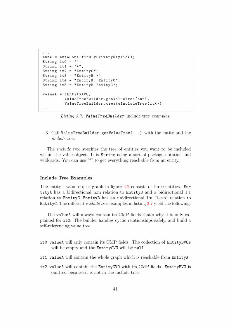
Listing 3.7: ValueTreeBuilder include tree examples.
3. Call ValueTreeBuilder.getValueTree(...) with the entity and theinclude tree.
The include tree specifies the tree of entities you want to be includedwithin the value object. It is String using a sort of package notation andwildcards. You can use ”*” to get everything reachable from an entity.
Include Tree Examples
The entity - value object graph in figure 4.2 consists of three entities. En-
tityA has a bidirectional n:m relation to EntityB and a bidirectional 1:1relation to EntityC. EntityB has an unidirectional 1:n (1->n) relation toEntityC. The different include tree examples in listing 3.7 yield the following:
The valueA will always contain its CMP fields that’s why it is only ex-plained for it0. The builder handles cyclic relationships safely, and build aself-referencing value tree.
it0 valueA will only contain its CMP fields. The collection of EntityBVOswill be empty and the EntityCVO will be null.
it1 valueA will contain the whole graph which is reachable from EntityA.
it2 valueA will contain the EntityCVO with its CMP fields. EntityBVO isomitted because it is not in the include tree.
41

it3 valueA will contain a collection of EntityBVO with its CMP fields. EachEntityBVO will contain the whole graph which is reachable from En-
tityB (EntityBVOs will contain a collection of EntityCVOs, which willalso reference back to EntityAVOs).
it4 valueA will contain a collection of EntityBVO with its CMP fields andthe EntityCVO with its CMP fields.
it5 valueA will contain collection of EntityBVO with its CMP fields. AllEntityBVO in addition will contain a Collection of EntityCVOs withits CMP fields (the EntityCVOs will not reference back to the En-
tityAVOs).
For the ValueTreeBuilder to work, all entities implement a getVal-
ueObject() method which returns a value object containing all CMP fieldsfor that entity.
42

Chapter 4
Results
In this chapter the results will be shown and experiences collected during thework on the extended cartridges will be discussed.
The software products developed on the Institute of Biomedical Engineer-ing - Bioinformatics Group [5] - are multi layered, web-based and data drivenapplications written in Java programming language and often based on theJ2EE platform. Therfor the integration framework was build based on EJBand Struts technology.
AndroMDA provides core functionality for code generation and deliversstandard cartridges for EJBs and Struts. The standard cartridges lack sev-eral disadvantages which were removed during the work on the extendedcartridges. The features added are listed below:
• Clean separation of business layer (EJB) and presentation layer (Struts)through the use of J2EE patterns for business interface, service locator,business delegate and value objects.
• Implementation of ”CRUD” (create, read, update and delete) methodsfor persistent objects in the business and presentation layer.
• A project wizard for creating new projects containing a default modelwhich minimises initial efforts.
The EJBs generated by the extended cartridge currently contain deploy-ment descriptors for the JBoss [13] application server. The EJB cartridgemust be adopted if other J2EE implementations should be supported.
43

The default model is stored in a *.zargo file readable for Poseidon CASEtool [8] because Poseidon Community edition if free of charge and used asthe default UML Case tool during development.
4.1 Extended Cartridges
The intention of extending the cartridges was to provide a better solutionfor modelling and programming data driven web applications. The extendedcartridge provides the following features:
• Bean-managed persistence Entity Beans
• Value object generation for entities
• Integration of ValueTreeBuilder [3.7.1] for building value object graphs
• Standard Struts actions for create, read, update and delete entities(”CRUD” methods)
• Standard struts-config.xml file with dynamic form beans
• Standard JSPs for listing, adding, editing and removing entities
• Service Locator pattern with Business Interface and Business
Delegate pattern.
This features will allow the programmers to generate quickly a powerful,multi layered, extendable data driven web application based on best practisepatterns, standard- and open source technologies.
4.2 Extended EJB Cartridge
The extended EJB cartridge provides all features of the standard cartridgewith the extensions described below.
44

4.2.1 Bean-managed Persistence Entities
The cartridge generates bean-managed persistence entity beans for each classwith the stereotype <<BMPEntity>>1. The cartridge can handle associa-tions between CMP and BMP entities. The code for the relation managementis put into an abstract bean classes of the CMP and BMP entities. Like incase of CMP beans there are also implementation classes for BMP beanswhere business and persistence logic implemented by the developer. Thisclass will be generated only once and will never be touched by the generatoragain2.
For n:m and unidirectional 1:n (1–>n) relations the developer must addfurther information to the model. This is performed by defining a classwith the stereotype <<EntityRelation>>. The relation class must havedependencies with the stereotype <<EjbRef >> to the corresponding en-tity classes and an attribute with the stereotype <<PrimaryKey>>. Therelation class will be implemented as a CMP entity bean with the speci-fied attribute as its PrimaryKey and two foreign keys of the correspondingentities3. Figure [4.1] shows an example for a unidirectional 1–>n relationbetween a CMP and BMP bean in the UML model.
For 1:n container-managed relations (CMR) you can define the Taggedvalue @andromda.cascade-delete of the association. This will cause a cas-cade delete on the n-side if the 1-side is deleted. For instance if you have a”Shop” to ”SalesAssistant” (1:n) relation and you remove a shop entity, all”sales assistants” who belong to that shop will also be removed4.
4.2.2 PrimaryKey Generator Factory
The extended cartridge uses the Factory pattern to get a PrimaryKey. List-ing 4.1 shows a snip of the create method in EntityA class. The interface,factory and implementation sources are included in the project wizard (seesec. 4.5).
1This name should perhaps be reconsidered in terms of PIM and PSM. BMPEntity istoo close to the EJB technology.
2It is the responsibility of the programmer to implement the persistence logic in theimplementation class.
3The implementation as CMP entity is the first attempt. Using direct database accessvia JDBC could perhaps have some advantages.
4Cascaded delete isn’t implemented yet for <<BMPEntity>>.
45

<<BMPEntity>>
EntityC
-idC : Long
-name : String
-discription : String
<<EntityRelation>>
EntBToEntCRelation
-relationId : Long <<EntityRef>>
<<Entity>>
EntityB
-idB : Long
-someDate : Date
-name : String
EntityB-MyBMPEntity0..*
<<EntityRef>>
This is a CMP Bean A BMP Bean
A relation table because unidirectional 1-->n relation.
It needs two <<EntityRef>> dep. to the entities and an attribute with stereotype <<PrimaryKey>>.
0..*EntityB-MyBMPEntity
<<EntityRef>> <<EntityRef>>
Figure 4.1: Example for bean-managed persistence entities.
...java.lang.Long pk =
PKGeneratorFactory.getPKGenerator(GlobalConstants.KEYGENERATORTYPE ).getPrimaryKey (" EntityA ");
...
Listing 4.1: PrimaryKey generator usage.
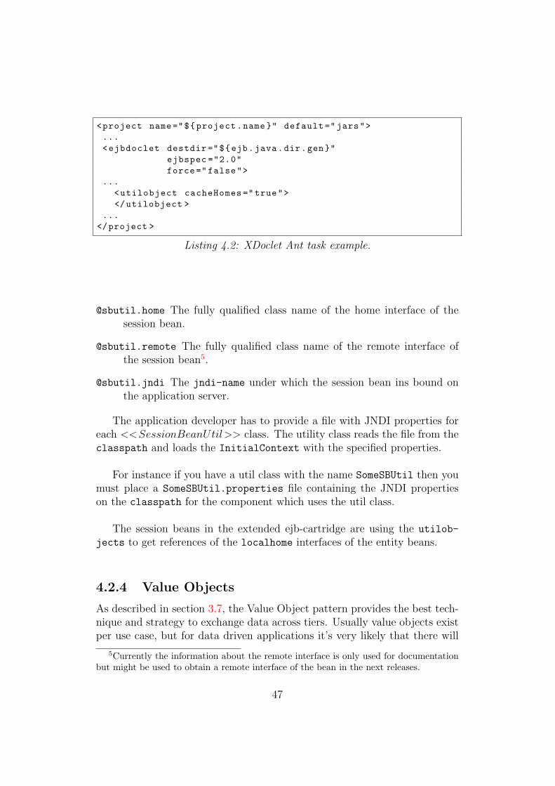
4.2.3 Util Classes
If specified in the XDoclet ant task, XDoclet generates utilobjects forenterprise beans. Basically these objects provide static helper methods forlooking up home and localhome interfaces in the Java Naming and DirectoryInterface (JNDI) repository of the application server. For further informa-tion about the XDoclet ant tasks, please visit the XDoclet home page [24].Listing 4.2 gives an example of an XDoclet task with activated utilobjects
generation.
The extended ejb-cartridge has also a template to generate utilobjects
for session beans. An utilobject is generated, if a class in the model hasthe stereotype <<SessionBeanUtil>> and the following tagged values aredefined:
46
<project name="${project.name }" default ="jars">...<ejbdoclet destdir ="${ejb.java.dir.gen}"
ejbspec ="2.0"force="false">
...<utilobject cacheHomes ="true"></utilobject >
...</project >
Listing 4.2: XDoclet Ant task example.
@sbutil.home The fully qualified class name of the home interface of thesession bean.
@sbutil.remote The fully qualified class name of the remote interface ofthe session bean5.
@sbutil.jndi The jndi-name under which the session bean ins bound onthe application server.
The application developer has to provide a file with JNDI properties foreach <<SessionBeanUtil>> class. The utility class reads the file from theclasspath and loads the InitialContext with the specified properties.
For instance if you have a util class with the name SomeSBUtil then youmust place a SomeSBUtil.properties file containing the JNDI propertieson the classpath for the component which uses the util class.
The session beans in the extended ejb-cartridge are using the utilob-
jects to get references of the localhome interfaces of the entity beans.
4.2.4 Value Objects
As described in section 3.7, the Value Object pattern provides the best tech-nique and strategy to exchange data across tiers. Usually value objects existper use case, but for data driven applications it’s very likely that there will
5Currently the information about the remote interface is only used for documentationbut might be used to obtain a remote interface of the bean in the next releases.
47

be ”CRUD” (Create, Read, Update and/or Delete) use cases for each entity.That’s why the value objects in the extended ejb-cartridge are mapped toentities.
A value object class in the model has the stereotype <<V alueObject>>and an association to an <<Entity>> or <<BMPEntity>> class. Thegenerated value object will have set/get methods for all attributes definedin the entity. In addition it will have set/get methods for other value ob-jects, reflecting the relations of the corresponding entity. Figure 4.2 showsan example for modelling value objects. In this example the EntityAVO willhave set/get methods for the attributes defined in EntityA and for its re-lated EntityCVO and EntityBVO. Entities without a value object, will not bereflected in the value object graph.
<<ValueObject>>
EntityCVO
<<ValueObject>>
EntityBVO
<<ValueObject>>
EntityAVO
Value Object for an Entity. See the documentation tab below for more information.
<<Entity>>
EntityA
-idA : Long
-someString : String
-someInt : int
<<Entity>>
EntityB
-idB : Long
-someDate : Date
-name : String
EntA-EntB
0..*
0..*
<<BMPEntity>>
EntityC
-idC : Long
-name : String
-discription : String
EntityB-MyBMPEntity
0..*
EntityA-ExternEntity
0..*
0..*
EntA-EntB
EntityBVO will have set/get method for a Collection of EntityCVOs and EntityAVOs
EntityB-MyBMPEntity
EntityA-ExternEntity
0..*
Figure 4.2: Example for value objects.
Entities with value objects will have the following methods in their ab-stract bean class:
ejbCreate(EntityVO:vo) The ejbCreate method will set the container-managed persistence fields according to the values in the vo and gen-erate a new PrimaryKey for the entity. The ejbCreate method doesnot check, whether the vo already contains a PrimaryKey.
ejbPostCreate(EntityVO:vo) The ejbPostCreate method performs therelation handling for the entity. This is not straight forward and needs
48

a more detailed inspection. If the entity has relations which are reflectedin the vo, then it will get the related value objects form the vo and calla helper method setEntityXVO(vo.getEntityXVO()).
setEntityXVO(EntityXVO:vo) If the vo is null, then the related entity willalso be set to null. Otherwise if the PrimaryKey of the vo is null thecreate(vo) method on the home interface will be called. If the Prima-ryKey is not null, the method will perform a findByPrimaryKey() andset the relation with the found entity6. See listing 4.3 for an example7.
getValueObject():EntityVO This method is required by the ValueTree-
Builder (see sec. 3.7.1) and returns a new value object with all CMPfields set to the values of the entity. The ValueTreeBuilder handlesthe relations using Java reflection.
update(EntityVO:vo) First it sets the CMP fields except for the primarykey field, then it utilises the helper methods setEntityXVO(vo.get-
EntityXVO()) to set the relations of the entity bean according to therelations in the vo.
4.2.5 Services and Standard Operations for Entities
Classes with the stereotype <<Services>> will be implemented as statelesssession beans. For all dependencies with the stereotype <<EntityRef >>which point to <<Entity>> or <<BMPEntity>> ”CRUD” methods inthe abstract session bean class will be generated. In addition the entities haveto define a tagged value @andromda.service.standardoperations with thevalue true, otherwise no standard operations will be generated.
CRUD methods in the session beans:
addEntityX(EntityXVO:vo):PrimaryKey This Method will create a newentity with the given value object vo and return the PrimaryKey ofthe newly generated entity. CreateException and NamingException
will be converted to component exception (see sec. 3.3.2).
6With this mechanism it is possible to create a bunch of entities with only one valueobject graph.
7EntityA to EntityB could be a n:m or 1:n relation
49

...
// ---- postCreate Helper Methods for relations ----
public void setEntityBVOs(java.util.Collection entityBs)throws javax.ejb.FinderException ,
javax.naming.NamingException ,javax.ejb.CreateException
{if ( entityBs == null ) {
setEntityBs (( Collection)null);} else {
Collection col = new ArrayList ();java.util.Iterator iter = EntityBs.iterator ();while(iter.hasNext ()) {
EntityBVO someVO = ( EntityBVO)iter.next ();java.lang.Long id = someVO.getIdB ();EntityBLocalHome entityBLH =
EntityBUtil.getLocalHome ();EntityB entityBRef;if (id != null && !id.toString (). equals ("") &&
!id.toString (). equals ("0")) {entityBRef = entityBLH.findByPrimaryKey(id);entityBRef.setEntityA(
(EntityA)this.context.getEJBLocalObject ());} else {
entityBRef = entityBLH.create(someVO );entityBRef.setEntityA(
(EntityA)this.context.getEJBLocalObject ());}
col.add(entityBRef );}setEntityBs(col);
}}...
Listing 4.3: Helper method to set entity relations with value objects.
50

findEntityXById(PrimaryKey:pk, String:includeTree):EntityX CallsfindByPrimaryKey(pk) on the local home interface, calls the Value-
TreeBuilder with the found entity and the includeTree and returnsthe Value Object graph. NamingException will be converted to com-ponent exception.
findAllEntityXs(String:includeTree) Calls findAll() on the local homeinterface. Afterwards it calls the ValueTreeBuilder for each found en-tity and returns a Collection of value objects. NamingException willbe converted to component exception.
removeEntityXById(PrimaryKey:pk) Calls remove(pk) on the local homeinterface. RemoveException and NamingException will be convertedto component exception.
updateEntityX(EncityXVO:vo) Gets the primary key from the vo, if theprimary key is null, a component exception will be thrown. If the Pri-maryKey is not null, findByPrimaryKey(vo.getIdX()) will be calledon the localhome interface. Then the update(vo) method of the entityis called. FinderException, NamingException and CreateException
will be converted to component exception.
4.3 Service Locator and Delegate Patterns
Separating the presentation layer from the business layer is important formaintaining the code. For example it is a bad habit to work directly withEJB classes in the web interface. Any changes in the EJB layer would causea change in the web layer. Therefor the extended cartridges force the defini-tion of business interfaces, delegates and locator factories.
In this section the modelling and artefacts of these patterns will be ex-plained. Like an <<Entity>> is a persistent and durable component, a<<Service>> models workflows or use cases. These services should be ac-cessible for the next higher layer (presentation layer).
The extended cartridges define a <<ServiceBusinessInterface>> classwith dependencies8 to one or more <<Service>> classes. The business in-terface will be implemented as a Java interface which defines all business
8A dependency is an UML element and is used e.g. in a class diagram similar toassociations.
51

...EntityXVO vo = new EntityXVO ();...java.lang.Long id =SomeServiceFactory.getInstance (). addEntityX(vo);...
Listing 4.4: Example for a service call.
operations and standard operations of all dependent <<Service>> classes.
In addition to the business interface <<BusinessDelegate>> and<<ServiceFactory>> class must be defined. The delegate class will handlethe creation of services and delegate method calls to it. The factory works asa service locator and is responsible for creating the proper delegate classes.Listing 4.4 shows the use of the factory and business interface (i.e. in a Strutsaction class) for service calls.
4.4 Extended Struts Cartridges
The extended struts cartridge simplifies the generation of Struts actions, dy-namic forms, configuration files and JSPs for data driven applications. Foreach class with the stereotype <<StandardStrutsAction>> which has anassociation to an entity the cartridge will generate:
Action classes extending the LookupDispatchAction class. These classesprovide ”CRUD” methods for the corresponding entity. A convertermethod handles the conversion from form to value object and back.The cartridge generates the action mapping for the entity into thestandard-actions.xml file which will be included into the struts-
config.xml file as XML-include.
DynaValidatorActionForm definitions for the corresponding entity into thestandard-forms.xml file which will be included into thestruts-config.xml file as XML-include.
JSPs to add, edit and remove entities.
Validator definitions for the dynamic forms. The tagged values @an-
dromda.struts.validation.depends and @andromda.struts.vali-
dation.fieldtags of attributes in the entity will generate entries in
52

<form -validation >...<formset >
...<form name=" EntityXForm">
...<field property ="name" depends ="required ,mask">
<var ><var -name >mask </var -name ><var -value >^[a-zA-Z]*$</var -value >
</var ></field >...
</form >...
</formset >...
<form -validation >
Listing 4.5: Validator example.
the standard-validation.xml file. Listing 4.5 shows the output forthe tagged values in table 4.1 where XXX=<var>...</var>.
Standard navigation menu to find all and add new entities. The Main-
Menu Servlet reads a menu definition file (in xml format) and handlesthe menu interaction for the web interface. The source for the MainMenuServlet is included in the project wizard.
Each <<StandardStrutsAction>> class has to have a dependency to a<<ServiceFactory>> class. The actions will use the factory like in case oflisting 4.4.
Tag Value
@andromda.struts.validation.depends required,mask
@andromda.struts.validation.fieldtags XXX
Table 4.1: Validator tags example for an attribute of an entity.
53

4.5 Project Wizard
The project wizard helps to create a new project and can be downloadedfrom the CVS repository. The wizard is actually an ant task, which readsthe properties defined in the wizard.properties and performs some copyingand renaming. Before calling the wizard, the wizard.properties file has tobe edited. To run the wizard, a command window (or shell) must be opened.After changing to the wizard directory the ant task can be called:
ant -f wizard.xml -Dproject.home=<PROJECT_DIRECTORY>
This will create the default project in the specified directory. The projectconsists of several directories described in table 5.5, an Ant bild.xml file anda JBuilder (an IDE from Borland [14]) project file. Additionally a defaultUML model in the uml-source directory for Poseidon UML CASE tool [8] willbe created. It has predefined stereotypes and contains diagrams for domain-,value object-, util- and standard struts action classes. It is recommendedto start with this model and run through the generation process with thepredefined classes.
To run the generator change to the project directory and call:
ant
The command window will output several information about the gen-eration process. Fist the model is read from the specified XMI file, thenAndroMDA locates the cartridges on the classpath and generates the code(marked with XDoclet). Then the XDoclet code generation task is called. Atthe end follows compilation, copying, archiving and deployment. The tasklogic and dependencies are defined in the build.xml file.
To list all ant tasks which are defined in the build.xml file call:
ant -projecthelp
This will output a list of ant tasks for the build.xml in the project di-rectory (see table 5.4 in the appendix).
54

<server >...<attribute name="URLs">
deploy/,file :///C:/ projects/SomeProject/build/</attribute >
...</server >
Listing 4.6: Example for an URL entry of the jboss-service.xml file.
4.5.1 Project Directory Structure
Table 5.5 in the appendix lists the project directory structure and its mean-ing.
The build directory contains subdirectories with the extracted EJBsand Web application. During development it is useful to let the JBossURLDeploymentScanner watch the build directory, if the ejb-jar.xml andweb.xml files change, JBoss will start a redeployment. Therefor in thejboss-service.xml file in the conf directory the projects build directorymust be added to the URL list. Listing 4.6 gives an example how the URLsattribute could look like.
It is useful for web development to modify the JSPs without redeploy-ment. Just edit the JSPs in the build directory and reload the browser. Thechanges can bee seen without redeploying the whole web application
55

Chapter 5
Discussion
This chapter will sum up the experiences which have been made during thework with AndroMDA and point out some general aspects for generationdriven software development.
AndroMDA with the extended cartridges provide an extendable and pow-erful integration framework based on standard technologies (UML, XMI,EJB, JSP, Servlets etc.) and Open Source products (Ant, XDoclet, Ve-locity, Struts, JBoss). It allows fast design and prototyping for data drivenweb applications and speeds up the development process as well as providesbetter maintainability, robustness and consistency. By the use of the ”projectwizard” (see sec. 4.5), the initial efforts are decreased. The ”UML TemplateModel” provides a good starting point for modelling and development.
The integration of generative software development has several drawbacksat the beginning of its introduction: programmers are faced with new tech-nologies; school enrolment and training for developers who have little expe-rience with code generators, modelling and UML CASE tools ; restructuringthe development team; and more. Benefits will only turn out at a later date:when the team is used to the new techniques used for development; appli-cations have to be ported to new upcoming technologies; architecture designchanges have to be made on existing code because of performance issues; andmore.
56

5.1 Pros and Cons for Code Generators
Code generators give programmers the potential for faster development andgenerally shorten the time to market for an application. The maintainabil-ity, consistence and robustness increases the more code is generated. Designpatterns can be easily converted into the generator templates, adopted andextended for the projects requirements (if the code generator is not a closedframework). In case of AndroMDA the templates and even the core genera-tor are open source and therefor extendable without any limitations.
Project managers should consider an initial cost for establishing code gen-erators. Some programmers must be familiar with the generator templatesand the core technology to adopt them for the project needs. The otherprogrammers will basically focus on business integration without any tech-nical and architectural design challenges, which may reduce their motivation.
5.1.1 MDA Approach
Currently MDA is strongly promoted and more implementations and toolsare available claiming to support the MDA architecture.
It is a fact that there are different lifetimes for the models of business pro-cesses (i.e B2B etc.), the software integrations and the implementation tech-nologies (J2EE, .Net, CORBA etc.). To decouple these levels of modellingand the approach to define transformations between the models types (whichactually describe the same but with different views) is an important step to-wards reusability, portability (platform independence) and interoperability.These are the key goals of the MDA approach, but if they can be reachedis a question of the acceptance of the market. Especially the interchange ofmodels between different MDA solutions (although XMI technology) will bechallenging. For instance the XMI DTD for UML 1.3 standard exists since1999 but interchanging the models between several CASE tool providers is aelaborate work.
5.2 AndroMDA is Work in Progress
AndroMDA provides a so called ”MDA light” solution. Most of the PSM ispart of the templates which directly generate the implementation for of the
57

PSM. In other words, the PSM is omitted in AndroMDA and the implemen-tation is generated directly from a PIM with tagged metadata.
The current version (2.0.3 final) provides a stable, extendable code gen-erator framework for rapid software development. It is based on open sourcetechnologies and free of charge. The new features of release 2.0.3 final andfuture plans for release 3.0 are listed and discussed on TheServerSide.com1.
5.3 Cartridge Management and Model Trans-
formations
During cartridge development, a big lack of reusability was identified. Thismight be solved in release 3.0. after the introduction of model transformationbefore code generation (PIM to PSM). Putting generation logic into the Ve-locity templates hinders reusability because the lack of generalization for thetemplates (i.e. EJB 2.0 template extends EJB 1.1 and reuses functionality).
Developing cartridges is an error prone work. The ”edit-templates ->generate test code -> compile test code -> deploy test application” processtakes too much time. Each project will require minor changes for the codetemplates as requirements differ from project to project. Cartridge reusabil-ity will play a key role in the future context for AndroMDA.
The more cartridge will be developed, the more modelling restrictions willoccur and the PIM will change more to a graphical representation for the im-plemented technology. Either there will be restrictions for the PIM which willcomplicate cartridge development or additional modelling elements for eachcartridge will force the PIM to be more like an implementation model.
For each problem domain a metamodel should exist which describes thePIM. This model can be transformed to a PSM with transformation defini-tions. These definitions are not specified and will cause dependencies to theMDA tool providers.
1Follow the discussion about AndroMDAhttp://www.theserverside.com/home/thread.jsp?thread id=20801 (from September 10th,2003)
58

5.4 AndroMDA in the Bioinformatics Domain
Bioinformatics covers many different domain categories from a technical pointof view: data acquisition (i.e. DNA sequencing roboters); data validation(experimental results); data analysis and postprocessing (simulations, drugresearch etc.);
All these domains are data driven. Storing and retrieving biological datawill be basic requirements for many applications in the Bioinformatics do-main. The integration framework with AndroMDA and the extended car-tridges frees the programmers from standard design considerations and letthem focus on business requirements.
59

Appendix
XML elements in andromda-cartridge.xml
Element Description
<cartridge> The cartridge tag is used to delimit the cartridge descriptor and givea name to the cartridge.
<property> The <property> tag is used to define a set of key-value pairs for acartridge. These properties define which aspects of the target appli-cation’s architecture are generated by this cartridge. In the future,these properties will be used for automatic aspect-to-cartridge map-pings (not yet implemented).
<stereotype> This tag is used to declare the stereotypes that trigger the core mod-ule to use this cartridge. Example: The EJB cartridge declares the<<Entity>> stereotype because entities may be represented by en-tity beans.
<outlet> This tag is used to declare a logical outlet name that can later bemapped to a physical directory using the <andromda> task in thebuild.xml script.
<template> The <template> tag is used to describe the set of templates that willbe used to generate source code.
Table 5.1: The XML elements used in the andromda-
cartridge.xml file [2].
60

XML attributes for the <template> tag in andromda-cartridge.xml
Attribute Description Required
stereotype Specifies the name of the stereotype that should trigger theuse of this template.
Yes
sheet Specifies the path (relative to the cartridge root) for a tem-plate (*.vsl) file to use for code generation.
Yes
output-
Pattern
Specifies a pattern in java.text.MessageFormat syntax. Youcan use this pattern to tell AndroMDA how to constructoutput file names. The pattern can consist of any ordinaryprintable characters as well as some predefined placeholdersfor things that AndroMDA already knows about:{0} stands for the package directory of the class.{1} stands for the class name.{2} stands for the base part of the *.vsl file name.{3} stands for the name of the stereotype.
Yes
outlet Specifies the logical name of the outlet where the cartridgewill write the output files caused by this template.
Yes
overWrite Specifies whether the files already contained in <outlet>should be overwritten when AndroMDA runs a second time.
Yes
generate-
EmptyFiles
Specifies whether files should be generated even if the tem-plate did not produce any output. This can be used by thecartridge developer to decide if a certain file should be gen-erated based on the information in the model. Note: If thisproperty is set to ”false”, the template produces no output,if overWrite is set to ”true”, and an existing file is found(probably generated by a previous run), then this file is re-moved.
No, defaultis ”true”
transform-
Classname
Specifies a name of a java class that can be used to helpthe code generation templates. In some cases the velocityscripting language is not enough for what you would liketo do in your code generation template. You can solve thisproblem by writing a java class to extend the $transformobject in the template. One way to write your own helperis to extend the class SimpleOOHelper.
No
Table 5.2: Attributes of the <template> tag in the andromda-cartridge.xml file [2].
61

AndroMDA Ant Task Attributes
Attribute Description Required
basedir Specifies the path to the directory location of the case tools’XMI files.
Yes
includes This is the standard Ant includes attribute. Specifies anyfiles or directories with XMI files that AndroMDA shouldtry to process.
Yes
excludes This is the standard Ant excludes attribute. Specifies anyfiles or directories with XMI files that AndroMDA shouldnot try to process.
No
modelURL It can be used instead of the includes and excludes at-tributes to point directly at the location of your XMI file.It is useful if the model file is in a JAR and should not beunzipped. Unlike include it can only be used to process oneXMI file.
Yes
last-
Modified-Check
This turns on or off the ability to check the last modifieddate on files in order to determine whether or not they needto be re-rendered or not. The value of this attribute can be”true, false, yes, no”. By default, it is true, meaning thatthe last modified date should be checked and if the original.xml file has not changed the output file is not created again.This accelerates the build process because files that have notchanged will not get reprocessed.
No, defaultsto ”true”
velocity-
Properties-File
This is the path to the velocity.properties file. It is anoptional argument and by default is set to find the propertiesfile in the same directory that the JVM was started in.
No
Table 5.3: Attributes of the AndroMDA Ant Task [2].
62

Ant tasks and directory structure of the default project
Ant task Description
build Builds ejb.jar and web.warbuild-nogen Builds ejb.jar and web.war without Xdoclet tasksclean-action Removes generated struts action filesclean-all Removes all generated filesclean-build Removes all jars, wars, ears and class filesclean-common Removes generated common java filesclean-config Removes generated config filesclean-ejb-config Removes generated EJB config filesclean-ejb-java Removes generated EJB java filesclean-html Removes generated html filesclean-jsps Removes generated JSPsclean-test Removes generated test java filsdeploy Verifies and deploys generated ear in JBossdeploy-nogen Verifies and deploys generated ear in JBoss without XDoclet tasksjunit Init testdb and performs all JUnit regression tests.redeploy-ejbs redeploys EJBs and WebApp
Table 5.4: Ant tasks for the build.xml file in the defaultproject.
Directory Description
./documentation project documentation
./lib lib directory
./resources resource files come here
./src the source directory
./src/app application sources
./src/cartridges cartridges directory for the project, contains the ejb-, struts-, java-and simple-example-cartridges
./src/java java source files come here, the subdirectories contain ”generated”and”manual” directories
./src/web directory for the web application sources
./src/uml directory for UML model source files
./src/xml directory for XML source files
./build directory for the extracted EJBs and web application
./toInstall directory for the jar (EJB archive), war (web archive) and ear (en-terprise application archive).Table 5.5: Default project directory structure.
63

List of Modelling Elements
Table 5.6 gives a summary of the defined stereotypes for model elements andits purpose and meaning.
EJB Cartridge
Stereotype Element Meaning
BMPEntity class For bean-managed persistence Entity Beans
EntityRelation class For n:m or unidirectional 1->n [BMP-CMP] or[BMP-BMP] relations
ValueObject class Value object for an BMP or CMP entity
SessionBeanUtil class Helper class for looking up and caching a home in-terface
ServiceBusinessInterfaceclass Interface implemented by the delegate class; usedby the upper layers
BusinessDelegate class Implements the ServiceBusinessInterface anddelegates method calls to the underlying sessionbeans
TemplateService-
Factory
class Creates and caches instances of delegate classes
Struts Cartridge
Stereotype Element Meaning
StandardStrutsAction class Struts action class containing ”CRUD”methods foran entity
Java Cartridge
Stereotype Element Meaning
GlobalConstants class Project specific class, holding constants
Exception class Java Exception class
Table 5.6: Stereotypes for the extended cartridges.
64

Table 5.7 gives a summary of the defined tagged values for model elements andits purpose and meaning.
EJB Cartridge
Tagged Value / Element Meaning
@ejb.persistence /
class
The name of the table for the entity (i.e. table-name="ENTITY_XXX")
@ejb.persistence /
attribute
The name of the column for the attribute of an entity(i.e. column-name="ATT_XXX")
@andromda.service.-
standardoperations /class
Session beans will contain ”CRUD” methods for entitieswhich have this tag set to "true".
@andromda.-
cascade-delete /association between CMP en-tities
Deletes the related entities if entity is removed
@sbutil.home /
SessionBeanUtil class
Fully qualified class name for the home interface of thesession bean
@sbutil.remote /
SessionBeanUtil class
Fully qualified class name for the remote interface of thesession bean
@sbutil.jndi /
SessionBeanUtil class
The JNDI-name under which the session bean is boundon the application server
Struts Cartridge
Tagged Value / Element Meaning
@andromda.struts.-
validation.required /attribute
Declares which validation rules are required for the at-tribute of an entity
@andromda.struts.-
validation.fieldtags /attribute
Declares which field tags the validation rule should con-tain (needs the required tag above).
continued on next page
65

continued from previous page
Tagged Value / Element Meaning
@andromda.viewtype /
association
If the value is "ComboBox" the Edit/Add-JSP will containa ComboBox for selecting a related entity. If not specifiedthe Edit/Add-JSP will contain a TextField2.
@andromda.entity-
Relation /association
The association needs this tag if a relation to an BMPentity needs a <<EntityRelation>>. The value mustbe the class name of the <<EntityRelation>>3.
Table 5.7: Tagged values for the extended cartridges.
2The related entity must have an attribute "name" to work with ComboBox3This is not an ideal solution and there might be changes in the future!
66

Bibliography
[1] Web resource for microarray databases .http://www.biologie.ens.fr/en/genetiqu/puces/bddeng.htmlSeptember 10th, 2003
[2] AndroMDA introduced by Matthias B.http://www.andromda.comSeptember 10th, 2003
[3] Andromdas car rental example. Included in the binary and sourcedistribution.
[4] Ant.http://ant.apache.orgSeptember 10th, 2003
[5] Bioinformatics Group - Institute of Biomedical Engineering - GrazUniversity of Technology.http://www.genome.tugraz.at/September 10th, 2003
[6] Document Access Page on OMG.http://www.omg.org/technology/documents/index.htmSeptember 10th, 2003
[7] Enterprise JavaBeans Technology.http://java.sun.com/products/ejb/September 10th, 2003
[8] Gentleware.http://www.gentleware.com/September 10th, 2003
[9] Hibernate.http://hibernate.bluemars.net/September 10th, 2003
67

[10] J2EE Patterns.http://java.sun.com/blueprints/patterns/index.htmlSeptember 10th, 2003
[11] Java.http://www.java.sun.comSeptember 10th, 2003
[12] Java Server Programming, J2EE 1.3 Edition.http://www.wrox.comSeptember 10th, 2003
[13] JBoss.http://www.jboss.orgSeptember 10th, 2003
[14] JBuilder IDE from Borland.http://www.borland.comSeptember 10th, 2003
[15] Middlegen.http://boss.bekk.no/boss/middlegen/September 10th, 2003
[16] Model-View-Controller.http://java.sun.com/blueprints/guidelines/September 10th, 2003
[17] Netbeans.http://www.netbeans.org/September 10th, 2003
[18] OMG Object Management Group.http://www.omg.org/September 10th, 2003
[19] OMG’s UML Unified Modeling LanguageTM.http://www.omg.org/umlSeptember 10th, 2003
[20] OMG’s Unified Modeling Language (UML).http://www.omg.org/gettingstarted/what is uml.htmSeptember 10th, 2003
[21] Struts.http://jakarta.apache.org/struts/September 10th, 2003
68

[22] The NCBI Handbook.http://www.ncbi.nlm.nih.gov/booksSeptember 10th, 2003
[23] Velocity.http://jakarta.apache.org/velocity/September 10th, 2003
[24] XDoclet.http://www.xdoclet.org/September 10th, 2003
[25] Merkle B. Gemachte Vorschriften. iX 4/2003, S 114-117.
[26] Ball CA, Sherlock G, Parkinson H, Rocca-Sera P, Brooksbank C, CaustonHC, Cavalieri D, Gaasterland T, Hingamp P, Holstege F, Ringwald M,Spellman P, Stoeckert CJ Jr, Stewart JE, Taylor R, Brazma A, andQuackenbush J. Microarray Gene Expression Data (MGED) Society.Science, 298:539–539, 2002.
[27] Roos DS. COMPUTATIONAL BIOLOGY: Bioinformatics–Trying to Swimin a Sea of Data. Science, 291(5507):1260–1261, 2001.
[28] Venter JC et. al. The sequence of the human genome. Science,291:1304–1351, 2001.
[29] CRICK F. Central Dogma of Molecular Biology. Nature, 227:561–563, 1970.
[30] Miller J and Mukerji J. MDA Guide Version 1.0, May 2003. DocumentNumber: omg/2003-05-01.
[31] Czarnecki K and Eisenecker UW. Generative Programming - Methods,Tools, and Applications. Addison-Wesley, June 2000.http://www.generative-programming.org/September 10th, 2003
[32] Schmaranz K. Ausgewahlte Kapitel der Softwareentwicklung -Programming for Large Libraries.http://courses.iicm.edu/ak swent/AKSWE Skriptum.pdfSeptember 10th, 2003
[33] Bohlen M and Starke G. MDA Entzaubert. Objektspektrum, March 2003.http://www.objektspektrum.deSeptember 10th, 2003
69

[34] Schena M, Shalon D, Davis RW, and Brown PO. Quantitative monitoring ofgene expression patterns with a complementary DNA microarray. Science,270:467–470, 1995. PM: 7569999.
[35] Volter M Stahl T. Moderne zeiten. IX 03/2003 S. 101, March 2003.http://www.heise.de/ix/September 10th, 2003
[36] Markus V. Code Generation: A survey of Concepts, Techniques and Tools.www.voelter.de/data/presentations/ProgramGeneration.zipSeptember 10th, 2003
70