this publication is not intended for distribution in the usa ...synthes.vo.llnwd.net/o16/llnwmb8/int...
TRANSCRIPT

This publication is not intended for distribution in the USA.
PRODUCT RATIONALE &SURGICAL TECHNIQUE

1
CONTENTS
Design Rationale
GLOBAL® APG+ Instrument Design Rationale............................2
Features and Benefits of Instruments ........................................3
GLOBAL Anchor Peg Glenoid Design Rationale .........................5
GLOBAL APG+ Key Surgical Steps .............................................7
Surgical Technique
Pre-Operative Planning .............................................................9
Glenoid Exposure ...................................................................10
Sizing – Sizer Pin Guides No Version Correction ........................................................12 Version Correction ..............................................................12
Pin Placement - Sizer Pin Guides .............................................13
Pin Placement and Sizing – Fixed Pin Guide .............................14
Reaming - Normal Exposure ....................................................15
Reaming - Challenging Exposure .............................................16
Drilling Central Peg Hole and Guide Pin Extraction ..................17
Drilling Peripheral Peg Holes ...................................................18
Trialling ...................................................................................19
Applying Bone Paste ...............................................................20
Cement Application ................................................................21
Seating the Implant and Wound Closure .................................22
Advanced Solutions
PREMIERON™ X-Linked Polyethylene .......................................25
GLOBAL Keeled Glenoid .........................................................26
Global Advantage™ .................................................................27
Global AP™ .............................................................................28
Key Information
Instrument Case Layout ..........................................................29
Ordering Information and Instrument Usage Diagram .............30

Ease of UsePSV
2
GLOBAL APG+ INSTRUMENT DESIGN RATIONALE
GLOBAL APG+ instrumentation is an advanced cannulated instrumentation system that provides accurate placement, orientation, and precise bone preparation for optimal implantation of the GLOBAL Anchor Peg Glenoid. The instruments were designed for ease of use and heightened efficiency in the operating room by incorporating features that enhance versatility, speed, and precision through a streamlined surgical approach. GLOBAL APG+ is designed to be used with either the GLOBAL ADVANTAGE or GLOBAL AP Shoulder Arthroplasty Systems. Both arthroplasty systems combine innovative designs and durable materials with proven clinical success.1
Advanced Instrumentation
Versatility
Versatility in an instrument set allows surgeons to more easily
and effectively complete a successful procedure by tailoring
their approach to the needs of the patient, as well as their
own individual preferences. The GLOBAL APG+ instrument
set is designed to allow the surgeon to select the best surgical
strategy options for each patient. Some of the options include:
•Use of pre-operative imaging
•Ability to assess and correct excessive glenoid retroversion through multiple pin placement devices
• Instrument features that provide solutions for normal and challenging exposure cases
All necessary instruments are included in the system to help the surgeon to complete the procedure with an intuitive and uncomplicated approach. Versatile options are designed into the GLOBAL APG+ instrumentation set for use at multiple steps during the surgical procedure.
SpeedThe efficiency of a surgical procedure is of the utmost importance in an operating room setting as it will minimise the amount of time a patient must be sedated, the time that room is unavailable, and ultimately the cost associated with that surgery. Total shoulder arthroplasty requires many complex instruments that need to interact with one another. Making the instrument connections, additions, and modifications less-laborious increases user-friendliness and improves functionality. These instruments are designed to attempt to reduce the time during and between surgical steps, therefore potentially reducing the overall length of the procedure. If this proved successful there would be decreased costs, and a reduction in patient risks, such as infection which may accompany a lengthy surgical procedure.
PrecisionA major design feature that provides an advanced level of precision while enhancing speed and efficiency at the same time is cannulation. An ingenious breakaway guide pin, whose length can be adjusted by the surgeon according to the size of the patient, was developed specifically to allow the instruments used in various steps to be advanced down its selected length. The centre of the glenoid fossa is maintained from step to step by using the cannulated approach.
V S
P

3
FEATURES AND BENEFITS OF INSTRUMENTS
Low Profi le Central Reamer(40/44 or 48/52/56)
When used with the Low Profi le Peripheral Reamer, assists insuccessful reaming in patients with challenging glenoid exposure. The half-moon shape aids insertion past the humerus. The glenoid-friendly blunt leading edge reduces the risk of bone fracture and interference with retractors. Cannulation and the quick connect end facilitate fast and easy use. Colour-coded banding matches corresponding Low Profi le Peripheral Reamer, Central Drill Bit, and trial.
Low Profi le Peripheral Reamer (40, 44, 48, 52, or 56)
When used with the Low Profi le Central Reamer, assists in successful reaming in patients with challenging glenoid exposure. Removes bone from the superior and inferior aspects of the glenoid simultaneously. Cannulation and quick connect end facilitate fast and easy use. Colour-coded banding matches corresponding Low Profi le Central Reamer, Central Drill Bit, and trial.
VV
Quick ConnectDriver Shaft
The quick connect end enables fast and easy connections between instruments. Cannulation provides for fast insertion over guide pin.
Access Reamer(40, 44, 48, 52, or 56)
The half-moon shape aids insertion past the humerus. The glenoid-friendly blunt leading edge reduces the risk of bone fracture and interference with retractors. Cannulation and quick connect end facilitate fast and easy use. Colour-coded banding matches corresponding Central Drill Bit and trial.
S S
Sizer Pin Guide (40, 44, 48, 52, or 56 -- +0, +3, or +5)
Assists in sizing and placement of guide pin in the centre of the glenoid using the best-fi t guide for that patient. Also assists in assessment and correction of retroversion using the +3 or +5 step heights (5 or 10 degrees respectively).
PCurved Handle
Assists in placement and rotational control of sizer pin guides. Cannulation enables placement of guide pin directly through the Curved Handle/Sizer Pin Guide assembly, while maintaining good visualisation. May also be used to control the length of the breakaway guide pin.
V
2.5 mm Breakaway Guide Pin
Multiple guide pin lengths can be selected by using the versatile breakaway grooves.
Fixed Pin Guide
Enables the placement of a guide pin without pre-operative planning by reference to the junction of the anterior glenoid neck and the scapular body regardless of glenoid version.
PV

4
Peripheral Drill Guide
Facilitates accurate drilling of three peripheral holes. Colour- coded hole locations match Quick Connect Peripheral Drill Bit for easy identifi cation.
Anti-Rotation Peg
Provides rotational stability for Peripheral Drill Guide for drilling peripheral peg holes. Flat edges of the peg head fi t securely into the Anti-Rotation Peg Inserter/Remover. Colour-coded banding matches corresponding hole location of Peripheral Drill Guide.
PP
Quick Connect Central Drill Bit (40/44 or 48/52/56)
Built-in stop enables quick drilling of central hole without a drill guide for the Anchor Peg Glenoid. Cannulation and quick connect end facilitate fast and easy use. Colour-coded banding matches corresponding reamers and trial.
SQuick Connect Peripheral Drill Bit
Quick connect end facilitates fast and easy use. Flat medial surfaces bottom out on the drill guide and provide depth stop. Colour-coded banding matches corresponding drill holes on the Peripheral Drill Guide.
S
Bone Graft Applicator
Facilitates application of correct amount of cancellous bone autograft to the fl utes of the Anchor Peg Glenoid.
P
Anti-Rotation PegInserter/Remover
Side-capture feature creates rotational stability, control, and quick connection for easy placement of Anti-Rotation Peg. Sturdy construction facilitates easy transfer of force for insertion or removal.
SGlenoid Grasper
Securely grips Trials and implants superiorly and inferiorly. Arms are set at an angle to provide easy introduction into the wound.
V

5
GLOBAL ANCHOR PEG GLENOID DESIGN RATIONALE
Advanced Fixation
The GLOBAL Anchor Peg Glenoid design:
•Provides a proven method of fi xation
•Addresses long-term fi xation and stability concerns
•Works with the GLOBAL ADVANTAGE and GLOBAL AP Shoulder Arthroplasty Systems
The patented GLOBAL Anchor Peg Glenoid achieves immediate stability with the three minimally cemented peripheral pegs, and provides a proven method of fi xation through an interference fi t of the central peg. The central peg facilitates bony integration around the fl utes for increased fi xation strength and resists “rocking horse” loosening. A study by Wirth et al. showed that mean fi xation strength increased signifi cantly within three months and remained strong six months postoperatively in a weight-bearing animal study. Improved fi xation was confi rmed radiographically and histologically, and the central fl uted peg achieved bone ingrowth in all cases.2

HEAD52
52
6
Advanced Biomechanics
DePuy Synthes Joint Reconstruction glenoid products have been designed with a constant 6 mm diametric mismatch between the glenoid and the humeral head component that:
• Is designed to emulate anatomic biomechanics of a healthy shoulder
•Optimises load transfer3
• Is designed to promote a more natural range of motion
• Is designed to help reduce the potential for rim loading
In a study of 56 retrieved glenoid components, the mismatch nonconforming designs had less surface damage, less radiolucency, and less impingement and edge abrasion than conforming designs.5
Advanced Wear Reduction
DePuy Synthes Joint Reconstruction offers tailor-made polyethylene solutions optimised for the unique demands of each joint. PREMIERON X-Linked Polyethylene for the shoulder balances wear reduction and mechanical integrity while maintaining oxidative stability. PREMIERON polyethylene has demonstrated an 85% reduction in wear debris over conventionally manufactured and sterilised components.4 In shoulder simulator testing, the GLOBAL Anchor Peg Glenoid with PREMIERON polyethylene signifi cantly lowered the calculated osteolytic potential, and thus the risk of aseptic loosening.4

7
1. Release Posterior Capsule
3. Drilling Central Peg Hole
2. Expose Glenoid
Glenoid Exposure
Glenoid Preparation and Implantation
1. Pin Placement, Sizing and Retroversion Correction
2. Reaming
Normal Exposure
Sizer Pin Guides (No Version)
Fixed Pin Guide(Version or No Version)
Sizer Pin Guides (Version)
Challenging Exposure
GLOBAL APG+ KEY SURGICAL STEPS

Ease of UsePSV
8
4. Drilling Peripheral Peg Holes
5. Trialling 6. Applying Bone Paste 7. Seating the Implant

9
PRE-OPERATIVE PLANNING
Pre-Operative Templating
Initial assessments of the glenoid bone should be carried out using radiographic imaging to determine if the patient is suitable for treatment (Figure 1). Additional information obtained from CT imaging can help determine appropriate treatment. At this stage, measurements can be identified for the angle of the plane of the scapula, the plane of the glenoid fossa, glenoid version, as well as size of the glenoid vault. One major pre-operative goal is to determine how much (if any) retroversion correction is necessary (refer to Table 1 on page 12). Corresponding information from the humeral component of the joint is also assessed at this time.
Surgical Approach
The patient rests in the beach chair position for the surgical procedure (Figures 2 and 3). The GLOBAL Anchor Peg Glenoid should be implanted using the delto-pectoral approach, humeral head resection, and canal preparation as described in the GLOBAL ADVANTAGE or GLOBAL AP surgical technique. This enables a good view of the inferior part of the glenoid, and is also advantageous for revision surgery where the difficult task of removal of the humeral stem can be accomplished. Using this approach, a full 360 degree exposure of the bony glenoid should be achieved. Sufficient posterior displacement of the proximal humerus is required to provide necessary exposure for implanting the GLOBAL Anchor Peg Glenoid. This degree of posterior humeral displacement frequently requires a posterior capsule release from the posterior glenoid rim in addition to an anterior and inferior capsular excision. To maintain this exposure a Modifed Sonnabend humeral head retractor is used to lever against the humeral broach or osteotomy cover, that is left in place to protect the proximal humerus.
Note: Failure to resect the entire humeral head at its anatomic neck may limit glenoid exposure.
Figure 2
Figure 3
Figure 1

10
GLENOID EXPOSURE
Before beginning glenoid exposure for preparation of the glenoid, it is very useful to inspect the posterior aspect of the capsule and glenohumeral space. Place the patient’s arm in a position so that the humeral osteotomy is parallel to the glenoid fossa. This is generally with the forearm perpendicular to the fl oor and the humerus in slight abduction. Using an osteotomy cover to protect the resected humeral surface, position a Shoulder Spreader (Left or Right 03-401-060 & 03-401-061) and laterally displace the proximal humerus to create a space between the osteotomy surface and the glenoid. Open the blades of the Shoulder Spreader and have an assistant hold the retractor to prevent rotation. Use a Double Prong Gelpi (2245-10-001) to retract the superfi cial soft tissues while placing a Reverse Hohmann Retractor (2245-10-040) between the remaining inferior capsule and neurovascular structures (axillary nerve and posterior humeral circumfl ex vessels) to achieve a clear view of the interval between the humerus and glenoid to the back surface of the capsule.
The posterior capsule is then released from the posterior glenoid rim (Figure 4). In cases with a very tight posterior capsule (prior surgery or post traumatic arthritis), it can be excised with this exposure. In addition, the posterior labrum can be easily visualised for excision along with removal of the remaining part of the long head of the biceps. Most importantly, this step will allow for complete removal of the anterior inferior capsule with excellent visualisation and protection of the axillary nerve. At this step, any osteophytes are removed, and the tissue is then placed back into physiologic tension thereby facilitating increased access and safety.
Figure 4

11
GLENOID EXPOSURE
Final exposure of the glenoid requires the use of a select set of deep retractors. A Small Anterior Glenoid Neck Retractor (2810-17-000) is placed over the anterior glenoid rim and is used to retract the subscapularis and the anterior soft tissues. The arm is then gradually positioned in extension, external rotation, and abduction. A proximal humerus spreader (2245-10-100) is positioned with the medial foot plate at the base of the coracoid and the lateral plate on the resected surface of the humerus to provide improved glenoid exposure (Figure 5). With ideal exposure the resected surface of the humerus is parallel to the posterior wall of the glenoid and posterior to the posterior glenoid rim thereby allowing full 360 degree exposure of the glenoid fossa. If needed, a Reverse Hohmann Retractor, is placed on the superior glenoid within the supraspinatus fossa to retract the superior part of the deltoid.
Full 360 degree exposure of the glenoid fossa is diffi cult in patients who have revision surgery, soft tissue scarring from a prior surgery, or malunions resulting from post traumatic cases. Patients who are very muscular or obese can also present exposure problems. In these cases, less than ideal exposure needs to be managed with respect to the instrumentation, alternative methods of retraction, and arm positioning to facilitate adequate exposure of the glenoid.
Note: Extensive capsular excision and release, along with proper resection of the humeral head, will correct most loss of motion commonly due to osteoarthritis, post capsulorrhaphy arthropathy, and post traumatic arthritis (including malunions). Soft tissue release often includes release of the long head of the biceps. These releases are essential for optimal glenoid exposure.
Figure 5

12
The 2.5 mm Breakaway Guide Pin is set in an orientation that may allow for an appropriate amount of retroversion correction (if necessary), and is placed using one of two pin placement devices – Sizer Pin Guides (+0, +3, or +5 mm), or a Fixed Pin Guide. The 2.5 mm Breakaway Guide Pin is scored in three locations (3, 4, and 5 inches from the tip) allowing smooth and controlled breakage. This feature allows the pin to be customised to a length appropriate to the patient and surgeon preference.
No Version Correction
Identify which Sizer Pin Guide (40+0, 44+0, 48+0, 52+0, or 56+0 mm) covers as much of the glenoid surface as possible without overhanging the periphery of the bone surface.
Version Correction
Identify which Sizer Pin Guide (40+3, 40+5, 44+3, 44+5, 48+3, 48+5, 52+3, 52+5, 56+3, or 56+5 mm) covers as much of the glenoid surface as possible without overhanging the periphery of the bone surface, and has the appropriate step height (+3 or +5 mm) (Figure 6) that will provide the amount of version correction required (5 or 10 degrees) based on preoperative planning or intra-operative assessment (See Table 1 and Figure 7).
Note: An implant that is too large will lack glenoid bone support and interfere with normal rotator cuff function.
SIZING - SIZER PIN GUIDES
Step Height (mm) Version Correction
+0
+3
+5
None
5°
10°
Table 1
Figure 6
Figure 7

13
Use the selected Sizer Pin Guide for the glenoid surface that allows placement of the 2.5 mm Breakaway Guide Pin (Figure 8) in the centre of the glenoid fossa. The viewing holes in the Sizer Pin Guide allow for visualisation of position and fi t. If there is intraoperative diffi culty in glenoid sizing, reference the planned size for the humeral head to determine which side of the joint needs to be adjusted.
Attach the cannulated Curved Handle to the hexagonal boss on the correct Sizer Pin Guide and centre on the glenoid fossa. This connection keeps the Sizer Pin Guide from rotating when held in place.
Insert a 2.5 mm Breakaway Guide Pin through the Curved Handle/Sizer Pin Guide assembly and drill securely into the glenoid fossa using a power drill (Figure 9). Remove the Curved Handle/Sizer Pin Guide assembly over the 2.5 mm Breakaway Guide Pin. The 2.5 mm Breakaway Guide Pin length may be adjusted at this point by placing the guide pin through the hole in the top of the Curved Handle just below the chosen score line and snapping the guide pin using the Curved Handle as a lever. The guide pin is now ready for the other cannulated instrumentation.
Note: The grooves on the 2.5mm Breakaway Guide Pin are exclusively used for the breakaway feature and are not intended to indicate the depth to which the pin should be inserted.
The pin is designed to break at the grooves. Be aware that it may break unintentionally if subjected to too much bending force.
After use of the Breakaway Guide Pin is complete, carefully check that all sections (totalling the full length of the original unbroken pin) have been removed.
PIN PLACEMENT - SIZER PIN GUIDES
Figure 9
Figure 8

14
Insert the tip of the Straight Handle Hex Driver through the top of the Fixed Pin Guide and engage it in the bottom portion. Tighten the Internal Rod of the Straight Handle Hex Driver through the external handle, which expands the hexagonal tip securing the driver to the Fixed Pin Guide.
Place the guide along the anterior wall of the glenoid until its tip reaches the lateral aspect of the subscapularis fossa. Identify the hole in the upper portion of the Fixed Pin Guide that corresponds to the centre of the glenoid fossa. Care needs to be taken that the inclination angle of the Fixed Guide Pin is set appropriately.
Insert a 2.5 mm Breakaway Guide Pin through the chosen hole of the Fixed Pin Guide directly and drill securely into the glenoid fossa using a power drill (Figure 10). Loosen the Internal Rod (Figure 11) of the Straight Handle Hex Driver to disengage from the Fixed Pin Guide. Remove the Fixed Pin Guide from the glenoid. The lower portion of the guide is designed to pivot away from the anterior glenoid for easy removal over the 2.5 mm Breakaway Guide Pin. The 2.5 mm Breakaway Guide Pin length may be adjusted at this point by placing the guide pin through the hole in the top of the Curved Handle just below the chosen score line and snapping the guide pin using the Curved Handle as a lever. The guide pin is now ready for the other cannulated instrumentation.
Identify which Sizer Pin Guide (40, 44, 48, 52 or, 56 -- +0, +3, +5) covers as much of the glenoid surface as possible without overhanging the periphery of the bone surface (refer to Figure 7 and Table 1 on page 12).
Note: The Fixed Pin Guide is designed to place the guide pin straight down the axis of the glenoid regardless of version. Inclination must be independently determined and set by the surgeon.
PIN PLACEMENT AND SIZING - FIXED PIN GUIDE
Figure 10
Figure 11

15
Attach the appropriately sized Access Reamer (40, 44, 48, 52, or 56 mm) to the Quick Connect Driver Shaft, and advance over the 2.5 mm Breakaway Guide Pin (Figures 12 and 13). Remove unwanted cartilage and bone from the surface of the centre portion of the glenoid fossa making sure to remove only as much bone as necessary (Figure 14). Remove the Access Reamer and Quick Connect Driver Shaft over the 2.5 mm Breakaway Guide Pin. Detach the Access Reamer from the Quick Connect Driver Shaft to ready the driver for the drilling step.
Note: It is important to prepare the surface completely before moving on to the next step. Care needs to be taken that there is congruent contact between the bone and the back side of the implant. The appropriately sized Sizer Pin Guide (+0) may be used to check contact.
Caution: Over-reaming decreases the surface area of the glenoid, decreases the depth of the glenoid vault, and removes the subchondral bone. All of these conditions can lead to suboptimal seating and support of the implant.
REAMING - NORMAL EXPOSURE
Figure 13 Figure 14
Figure 12

16
REAMING - CHALLENGING EXPOSURE
Attach the appropriately sized Low Profi le Central Reamer (40/44mm or 48/52/56 mm) to the Quick Connect Driver Shaft, and advance over the 2.5 mm Breakaway Guide Pin. The size and shape of the Low Profi le Central Reamer is designed to prepare the anterior/posterior portion of the glenoid fossa only, and a second step is needed to remove unwanted cartilage and bone from the superior/inferior portions. Remove unwanted cartilage and bone from the surface of the centre portion of the glenoid fossa making sure to remove only as much bone as necessary (Figure 15). Remove the Low Profi le Central Reamer and Quick Connect Driver Shaft over the 2.5 mm Breakaway Guide Pin. Detach the Low Profi le Central Reamer from the Quick Connect Driver Shaft to ready the driver for the drilling step.
Select the appropriately sized Low Profi le Peripheral Reamer (40, 44, 48, 52, or 56 mm), and attach to the Ratchet T-Handle from either the GLOBAL ADVANTAGE or GLOBAL AP instrument sets. Finish creating a uniform, concave surface across the entire glenoid fossa by manually operating the Low Profi le Peripheral Reamer (Figure 16) until its depth-stop bottoms out on the centre portion of the glenoid.
Note: It is important to prepare the surface completely before moving on to the next step. Care needs to be taken that there is congruent contact between the bone and the back side of the implant. The appropriately sized Sizer Pin Guide (+0) may be used to check contact.
Tip: Remove all retractors and use reamer shaft to retract soft tissue for extra room during challenging exposure cases.
Caution: Over-reaming decreases the surface area of the glenoid, decreases the depth of the glenoid vault, and removes the subchondral bone. All of these conditions can lead to suboptimal seating and support of the implant.
Caution: The Low Profi le Peripheral Reamer is NOT intended for use with power. If hard bone impedes bone removal, a Hand Burr may be used to conservatively remove problem areas. Care should be taken to avoid removal of too much subchondral bone as this may compromise implant stability.
Figure 16
Figure 15

17
Drilling Central Peg Hole
Attach the appropriately sized cannulated Quick Connect Central Drill Bit (40/44 mm or 48/52/56 mm) to the Quick Connect Driver Shaft, and introduce over the 2.5 mm Breakaway Guide Pin.
Advance the bit until it bottoms out on the reamed surface of the glenoid (Figure 17). The morselised bone captured during drilling the central hole should be saved for use as bone paste between the fl utes of the Anchor Peg Glenoid. Remove the Quick Connect Central Drill Bit and Quick Connect Driver Shaft over the 2.5 mm Breakaway Guide Pin.
Note: Use Quick Connect Central Drill Bit 40/44mm for implanting a 40 mm or a 44 mm Anchor Peg Glenoid. Use Quick Connect Central Drill Bit 48/52/56 mm for implanting a 48 mm, 52 mm, or 56 mm Anchor Peg Glenoid.
DRILLING CENTRAL PEG HOLE AND GUIDE PIN EXTRACTION
Figure 17
Figure 18
Guide Pin Extraction
Grasp and remove the 2.5 mm Breakaway Guide Pin using the Pin Extractor (Figure 18).
Note: After use of the Breakaway Guide Pin is complete, carefully check that all sections (totalling the full length of the original unbroken pin) have been removed.

18
Insert the tip of the Straight Handle Hex Driver into one of the hexagonal holes on the Peripheral Drill Guide. Tighten the Internal Rod of the Straight Handle Hex Driver expanding the hexagonal tip and securing the driver to the Peripheral Drill Guide. Insert the Peripheral Drill Guide into the central hole. It should fully contact the prepared bone surface on the glenoid fossa.
Connect the Quick Connect Peripheral Drill Bit to the Quick Connect Driver Shaft to prepare for drilling of the peripheral holes. The peripheral holes should not penetrate the base of the scapula. Drill the superior peripheral peg hole while holding the Peripheral Drill Guide in place (Figure 19).
Place an Anti-Rotation Peg into the newly drilled peripheral hole using the Anti-Rotation Peg Inserter/Remover (Figure 20). The peg will help prevent the Peripheral Drill Guide from shifting or rotating during the drilling of subsequent holes. This will ultimately enable the resulting peripheral hole pattern to precisely accommodate the peripheral pegs of the implant. Prepare the anterior and posterior holes using the same Quick Connect Peripheral Drill Bit.
Remove the Anti-Rotation Peg using the Anti-Rotation Peg Inserter/Remover.
Option: An alternative to holding the Peripheral Drill Guide in place is to use a 2.5 mm x 70 mm Fixation Pin. Insert a 2.5 mm x 70 mm Fixation Pin through one of two angled holes in the Peripheral Drill Guide directly and securely into the glenoid fossa (Figure 21). This alleviates the need to hold the Peripheral Drill Guide in place by hand, and allows for better visibility and manoeuvrability in the joint space.
Note: Check each peripheral hole to determine whether it penetrates the cortical wall of the glenoid vault. Penetrating holes are cemented but extra care is exercised to avoid pressurising the cement.
DRILLING PERIPHERAL PEG HOLES
Figure 19
Figure 20
Figure 21

Size 56
Size 52
Size 48
Size 44
Size 40
19
Insert the appropriate implant trial (40, 44, 48, 52, or 56 mm) (Figure 22) into the prepared glenoid using the Glenoid Grasper (Figure 23). Assess the fi t to determine that the trial sits fl ush with the prepared surface of the glenoid. There should be full and concentric contact between the back side of the trial and the prepared surface of the bone. If there is not full and concentric contact between trial and prepared bone surface, some or all of the prior bone preparation steps may need to be repeated. If the fi t is adequate, remove the trial, and fi nalise the bone preparation with pulsatile lavage or other means of thorough irrigation to remove any blood clots from the four drilled holes.
Note: Check the quality of the glenoid bone preparation by determining if the component is directly supported by precisely contoured bone, that should prevent the component from rocking, even when an eccentric load is applied to the rim of the implant.
Caution: Component loosening or excessive wear may occur if the glenoid component lacks suffi cient bone support.
TRIALLING
Figure 23
Figure 22

20
Use the Bone Graft Applicator to apply cancellous bone paste between the fl utes of the appropriately sized GLOBAL Anchor Peg Glenoid (40, 44, 48, 52, or 56 mm) to help facilitate tissue integration. Place the GLOBAL Anchor Peg Glenoid on a table with the articular surface down and the central peg fl utes up. Place the circular opening of the Bone Graft Applicator over the fl utes and open the handles to expose the central peg fl utes. Place the bone paste collected from drilling the central peg hole, or from drilling the underneath side of the humeral head, into the Bone Graft Applicator on both sides of the central peg fl utes (Figure 24). Close and hold the Bone Graft Applicator. At the same time, hold the GLOBAL Anchor Peg Glenoid at its base, and twist the Bone Graft Applicator several times back and forth (Figure 25). Pull the Bone Graft Applicator straight off leaving bone interposed evenly between the central peg fl utes (Figure 26).
APPLYING BONE PASTE
Figure 25
Figure 24
Figure 26

21
Obtain a hemostasis in each of the three peripheral holes.
Mix the SMARTSET® GHV cement until it has reached a doughly state and no longer sticks to surgical gloves. It is now ready for use.
Only a small amount of cement is necessary in each hole to provide the proper 1 mm cement mantle around each GLOBAL Anchor Peg Glenoid peripheral peg. Make sure no cement is in the central hole or on the back side of the implant that could inhibit proper seating.
Note: Excessive cement extruding from the drilled holes and lying between the prosthesis and glenoid fossa is undesirable. It may create an uneven mantle for the glenoid prosthesis, and cement may fragment with repetitive loading and become loose in the joint causing damage to the polyethylene surface.
CEMENT APPLICATION

22
Seating the Implant
Insert the fi nal implant using the Glenoid Grasper (Figure 27).
Use both the Universal Glenoid Handle and the polyethylene Glenoid Impactor Tip to seat the implant until there is complete contact between the back side of the implant and the prepared glenoid surface (Figure 28). The implant will be most stable when supported by precisely contoured bone. This support should prevent rocking even with unbalanced loads applied to the rim of the implant. Maintain direct pressure on the implant until the cement has hardened.
Note: Confi rm that the central hole is clear prior to implant insertion.
SEATING THE IMPLANT AND WOUND CLOSURE
Figure 27
Figure 28
Wound Closure
Verify soft tissue tension and range of motion after completing the humeral procedure according to the GLOBAL ADVANTAGE or GLOBAL AP surgical technique. Thoroughly irrigate the wound with antibiotic solution. After repairing the biomechanical aspects of the joint, take measures to manage short-term pain and limit formations of post-operative haematoma. The wound is closed according to surgeon preference.

23

24
Ease of UsePSV

25
The GLOBAL Keeled Glenoid is indicated for cases involving a tight joint compartment or compromised glenoid bone stock.
•Designed to work with GLOBAL ADVANTAGE and GLOBAL AP Shoulder Arthroplasty Systems
•6 mm diametric mismatch
•Manufactured with PREMIERON X-Linked Polyethylene
ADVANCED SOLUTIONS KEELEDGLENOID

26
The GLOBAL ADVANTAGE Shoulder Arthoplasty System is a proximal press-fit humeral stem that offers enhanced OR efficiency through a simple and repeatable surgical technique.
•Clinically proven proximal press-fit stem design with almost 20 years of GLOBAL Shoulder clinical success.1-6
•Recessed collar is designed to help optimise glenohumeral contact area
•Reverse Morse-type taper locking mechanism
•Designed to provide maximum surgical exposure with stem and broach
•Enables humeral head removal without removing stem
•Low profile standard and eccentric humeral heads
• Increase articular surface area by 25-33 percent over previous designs.7
ADVANCED SOLUTIONS

27
The GLOBAL AP Shoulder Arthoplasty System is the next generation proximal press-fi t DePuy Synthes Joint Reconstruction shoulder arthroplasty system that combines advanced engineering and almost 20 years of GLOBAL Shoulder success.1-6
•Collarless design provides for anatomic reconstruction of the proximal humerus with two neck options using a single surgical technique.8
•Fixed 135 degree neck angle for simplicity in uncomplicated arthroplasty
•Adjustable (120-150 degree neck angle and ±15 degrees version) for enhanced joint stability.
•Titanium alloy with POROCOAT® beading for optimised cementless application9
•Low profi le standard and eccentric humeral heads
•Revision long stem lengths up to 220 mm
ADVANCED SOLUTIONS
28
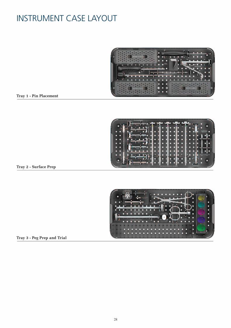
INSTRUMENT CASE LAYOUT
Tray 1 - Pin Placement
Tray 2 - Surface Prep
Tray 3 - Peg Prep and Trial

29
ORDERING INFORMATION
Part Number2236-00-1002236-00-1102236-00-1112236-00-1122236-00-1132236-00-300
DescriptionCASE COMPLETECASEPIN PLACEMENT TRAYSURFACE PREP TRAYPEG PREP AND TRIAL TRAYLID

30
DescriptionGLOBAL ANCHOR PEG GLENOID TEMPLATESIZER PIN GUIDE 40+0SIZER PIN GUIDE 44+0SIZER PIN GUIDE 48+0SIZER PIN GUIDE 52+0SIZER PIN GUIDE 56+0CURVED HANDLESIZER PIN GUIDE 40+3SIZER PIN GUIDE 40+5SIZER PIN GUIDE 44+3SIZER PIN GUIDE 44+5SIZER PIN GUIDE 48+3SIZER PIN GUIDE 48+5SIZER PIN GUIDE 52+3SIZER PIN GUIDE 52+5SIZER PIN GUIDE 56+3SIZER PIN GUIDE 56+5FIXED PIN GUIDESTRAIGHT HANDLE HEX DRIVER (INTERNAL ROD)STRAIGHT HANDLE HEX DRIVER (EXTERNAL HANDLE)2.5 mm BREAKAWAY GUIDE PINQUICK CONNECT DRIVER SHAFTAPG+ ACCESS REAMER 40 RUAPG+ ACCESS REAMER 44 RUAPG+ ACCESS REAMER 48 RUAPG+ ACCESS REAMER 52 RUAPG+ ACCESS REAMER 56 RUAPG+ LOW PROFILE CENTRAL REAMER 40/44 RUAPG+ LOW PROFILE CENTRAL REAMER 48/52/56 RULOW PROFILE PERIPHERAL REAMER 40LOW PROFILE PERIPHERAL REAMER 44LOW PROFILE PERIPHERAL REAMER 48LOW PROFILE PERIPHERAL REAMER 52LOW PROFILE PERIPHERAL REAMER 56RATCHET T-HANDLEAPG+ QUICK CONNECT CENTRAL BIT 40/44 RUAPG+ QUICK CONNECT CENTRAL BIT 48/52/56 RUPIN EXTRACTORPERIPHERAL DRILL GUIDEAPG+ QUICK CONNECT PERIPHERAL BIT RUANTI-ROTATION PEGANTI-ROTATION PEG INSERTER/REMOVER2.5 mm X 70 mm FIXATION PINTRIAL 40TRIAL 44TRIAL 48TRIAL 52TRIAL 56GLENOID GRASPERBONE GRAFT APPLICATORSMARTSET GHV 20gUNIVERSAL GLENOID HANDLEGLENOID IMPACTOR TIPGLOBAL ANCHOR PEG GLENOID 40 mmGLOBAL ANCHOR PEG GLENOID 44 mmGLOBAL ANCHOR PEG GLENOID 48 mmGLOBAL ANCHOR PEG GLENOID 52 mmGLOBAL ANCHOR PEG GLENOID 56 mm
Part Number2236-80-0982236-00-0012236-00-0022236-00-0032236-00-0042236-00-0052230-00-0232230-00-0032230-00-0042230-00-0062230-00-0072230-00-0092230-00-0102230-00-0122230-00-0132230-00-0152230-00-0162230-00-0182230-00-0242230-00-0252230-00-0192230-00-0292236-10-0082236-10-0092236-10-0102236-10-0112236-10-0122230-10-0302230-10-0312230-00-0322230-00-0332230-00-0342230-00-0352230-00-0362128-61-0702236-10-0142236-10-0152307-99-0042236-00-0162230-10-0952230-00-0992230-00-0218555-06-0002236-00-0182236-00-0192236-00-0202236-00-0212236-00-0222236-00-0172236-00-02330950202236-03-0002236-21-0001136-40-0261136-41-0261136-42-0261136-43-0261136-44-026
ORDERING INFORMATION
Instrument Usage Diagram Key Sizing and Pin Placement (No Version) Sizing and Pin Placement (Version) Fixed Pin Placement and Sizing Reaming Normal Exposure
Reaming Challenging Exposure Drilling Central Peg Hole Guide Pin Extraction Drilling Peripheral Peg Holes
Trialling Seating the Implant

References
1. Matsen FA III, Iannotti JP, Rockwood CA Jr. Humeral fixation by press-fitting of a tapered metaphyseal stem: prospective radiographic study. Journal of Bone and Joint Surgery. 2003;85A(2):304-308.
2. Wirth MA, Korvick DL, Basamania CJ, et al. Radiologic, mechanical and histologic evaluation of 2 glenoid prosthesis designs in a canine model. Journal of Shoulder and Elbow Surgery. 2001;10(2):140-148.
3. Williams GR, Abboud JA. Total shoulder arthroplasty: Glenoid component design. Journal of Shoulder and Elbow Surgery. 2005; 14:122S-128S
4. Wirth MA, Klotz C, Deffenbaugh DL, et al. Cross-linked glenoid prosthesis: a wear comparison to conventional glenoid prosthesis with wear particulate analysis. Journal of Shoulder and Elbow Surgery. 2009;18(1):130-137.
5. Nho SJ, Ala OL, Dodson CC, et al. Comparison of conforming and nonconforming retrieved glenoid components. Journal of Shoulder and Elbow Surgery. 2008;17(6):914-920.
6. Wirth A, Wirth R, Tapscott S et al. Treatment of glenohumeral arthritis with a hemiarthroplasty: A minimum five-year follow up outcome study. J Bone Joint Surg Am. 2006; 88;964-973
7. Norris TR, Iannotti JP. Functional outcome after shoulder arthroplasty for primary osteoarthritis: a multicenter study. Journal of Shoulder and Elbow Surgery. 2002; 11(2):251-258.
8. Jeong J, Bryan J, Iannotti JP. Effect of a variable prosthetic neck-shaft angle and the surgical technique on replication of normal humeral anatomy. Journal of Bone and Joint Surgery, 2009;91A(8)1932-1941.
9. Engh CA, Hopper RH. The odyssey of porous-coated fixation. The Journal of Arthroplasty. 2002;17(4); 102-107
©DePuy International Ltd. and DePuy Orthopaedics, Inc. 2014. All rights reserved.
depuysynthes.com
The third party trademarks used herein are the trademarks of their respective owners.
DePuy Orthopaedics EMEA is a trading division of DePuy International Limited.Registered Office: St. Anthony’s Road, Leeds LS11 8DT, EnglandRegistered in England No. 3319712
CA#DPEM/ORT/1112/0339 10001-01-004 Issued: 04/14
DePuy France S.A.S.7 Allée Irène Joliot Curie69800 Saint PriestFranceTel: +33 (0)4 72 79 27 27Fax: +33 (0)4 72 79 28 28
0459 0086
DePuy International LtdSt Anthony’s RoadLeeds LS11 8DTEnglandTel: +44 (0)113 387 7800Fax: +44 (0)113 387 7890
DePuy Orthopaedics, Inc. 700 Orthopaedic DriveWarsaw, IN 46582USATel: +1 (800) 366 8143Fax: +1 (574) 267 7196