(this page intentionally left blank) - wordpress.com inspector report ... hydrostatic test data tag...
TRANSCRIPT


(This page intentionally left blank)

1 May 15
USS GEORGE WASHINGTON (CVN 73) XO GRAM 5-15
GW Warriors,
I. Zone Inspections ensure:
a. Material and combat readiness.
b. Personnel and ship safety.
c. The ship operates throughout a 50 year service life.
II. Work together as a team during Zone Inspections. Be tough and uphold the high standards and expectations of USS GEORGE WASHINGTON.
III. UNSAT Zone Inspection Criteria:
a. All Repair-level 1 discrepancies, immediate danger to personnel or equipment. Zone Inspector report immediately to the Safety Officer/Damage Control Assistant, who will ensure these safety/damage control discrepancies are corrected within 24 hours. All degraded damage control fittings will be logged in the Out of Commissioned (OOC) Log in Damage Control Center (DCC).
b. Repeat discrepancies, documented material ZIDL hits from previous zone inspection that should have been resolved at the divisional level, but no corrective action was taken. If there is no ZIDL for zone inspector to review = UNSAT.
c. Damage control fire bottle missing from space or PMS date out-of-periodicity. Emergency Egress Breathing Device (EEBD) missing from space. EEBDs with an expiration date out-of-periodicity do not constitute an UNSAT grade, but need to be annotated on the space ZIDL.
d. Space not ready for zone inspection (unkept, debris on deck, trash bins not empty, gear adrift, excessive high dust, etc.).
e. Compartment Check-Off List (CCOL) missing = UNSAT.
K. A. STRONG
Enclosure (1)
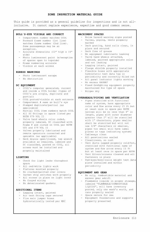
ZONE INSPECTION MATERIAL GUIDE
This guide is provided as a general guideline for inspections and is not all-inclusive. It cannot replace experience, expertise and good common sense.
BULL’S-EYE VISIBLE AND CORRECT - Compartment number matches CCOL - Forward frame number (1st line) matches frame number (2nd line). Some passageways may be an exception. - Accurate dimensions (12” high x 15” wide) - Photo luminescent paint (w/exception of spaces open to topside) - Frame numbering accurate - Visible at each access
EGRESS MARKINGS - Photo luminescent escape - No obstruction
DC EQUIPMENT - CCOL’s computer generated, current and inside a CCOL holder (types of CCOL’s are single, duplicate and partial) - CCOL posted/visible at each entrance - Compartment # same as bull’s eye - Stamped duplicate/partial (as applicable) - Partial CCOL item numbers match CCOL - All DC fittings in space listed per NSTM 079 VOL II - Valve hand wheels color coded, properly labeled, DC classified with frame # and listed on CCOL per NSTM 505 and 079 VOL II - Valves properly lubricated and remote operators connected and operable (as applicable) - Deck drains open/closed, tee wrench available as required, labeled and DC classified, posted on CCOL, all screws must be installed and properly maintained
LIGHTING - Check for light leaks throughout space - All red/white lights work - Fixtures mounted properly - No cracked/painted over covers - Darken ship switches work properly - All screws in place on light cover - No frayed wiring - No deteriorated gaskets
ADDITIONAL ITEMS - Lagging intact, painted - Air test fitting caps secured - Fire main jumper hoses hydrostatically tested per MRC
MACHINERY SPACES - Noise hazard warning signs posted - Valves, piping, vents properly marked - Deck grating, hand rails clean, in place and secured - Deck free of grease - No equipment lubricants leaking - Valve hand wheels attached, labeled, painted appropriate color and not leaking - Lagging intact, painted - Flange shields properly installed - Flexible hoses with appropriate hydrostatic test data tag in periodicity and correctly filled out - All panel indicator lights working - No excess HAZMAT - Fixed firefighting equipment properly maintained for type of space - Bilges dry
OVERHEADS/PIPING AND VENTILATION - Pipes stenciled with functional name of system, have appropriate color and flow arrow every 15 ft but at least once in space per NSTM (arrows will be no less than 4” in length, pipes with outer diameter greater than 2” will be stenciled with 1” characters, pipes smaller shall be stenciled but will not use 3/8” characters or smaller, pipes too small will have label plates or tags indicating system) - Cableways clean - All penetrations sealed - Cleanliness, no rust - Vent ducts lagged properly cold/hot, stenciled with functional name of system and flow arrow every 15 ft but at least once in space per NSTM - Vent filters/screens cleaned and all fasteners in place - Pad-eyes/mono-rails weight test data plate installed and within periodicity
EQUIPMENT AND GEAR - No oily, combustible material and excess gear adrift - Flammable liquids in proper stowage, labeled “FLAMMABLE/COMBUSTIBLE LIQUIDS”, will have inventory posted, only one week’s worth, and cans properly sealed - Space secure for sea - Equipment foundations and supports properly preserved
Enclosure (1)

ADDITIONAL ITEMS (CONTINUED) - Sounding tube fittings, classification and numbering - First aid, decontamination and traffic markings - Porthole, hatch, dogging wrench, T-wrenches and ventilation weather closure open and/or closed, end wrenches on station (as applicable) - Damage control shoring - Medical stretchers (as applicable) - Posted safety precautions, warning signs, and operating instructions - Posted first aid instructions (4 step) - Safety nets in trunks, properly tagged, no tears or worn straps and all hooks/eyes in place - First aid boxes with tamper seal intact - Inspect for unauthorized flammable materials - Frame numbering at least once in a compartment < 24 ft in length and every 24 ft in compartments > 24 ft in length - Installed/portable eye wash stations operational, PMS current, alarms operational. - Verify any danger/caution tags are filled out properly per TUMS/JFMM
BATTLE LANTERNS - Rubber boot free of cracks/tears - Operates, in good physical condition - Illuminates vital gage boards/escape routes - Properly mounted (fixed units not able to be removed from bracket) - Battery power sufficient, no leaks
CO2 BOTTLE - Record tag per MRC - Bracket secured to bulkhead - Tamper seal intact and snug - Horn and hose assembly free of paint, no deterioration - No electric tape on valve metal fitting - CO2 decal in place
FIRE STATION - Hose neatly stowed 6” off deck on camel - No verdigris on interior/exterior of nozzles, strainers, hose couplings and Y-gates - Current Hydrostatic date on hose - Fire plug (FPL) bull’s-eye correct, red/white characters (8 1/2”H x 18” W) and lists FPL and all COVs for FPL - Navy vari-nozzle on hose and in bracket - Y-gate connection to hose is secured and connection without hose is open - Necessary equipment to operate FPL must be on station per MRC
EQUIPMENT AND GEAR (CONTINUED) - Gauge calibration within periodicity - Gauge pointers properly set (red) - LP air station oil lubricator filled
ELECTRICAL SAFETY - Extension cords, appliance and tools safety checked - High voltage warnings posted (as applicable) - Casualty power terminals posted and have T-wrenches - Emergency casualty power cables properly identified with number of cables, lengths and stowed - No frayed or exposed dead ended electrical cables - Electrical outlets labeled and intact - Sound powered phone receptacles covered, labeled, intact and wire lanyard installed to cover - One wire per stuffing tube/cables penetrate via stuffing tubes only - Stuffing tube packed - Power/lighting distribution panels labeled and intact - No unauthorized electrical/ electronic equipment (i.e., refrigerators, coffee pots, fans, microwave, WTR cooler, etc. without proper authorization form) - Power panel megger holes plugged - Circuit breaker boxes have no voids - Vent controllers DC classified and listed on CCOL - Electrical panels, controllers, boxes cover bolts in place
EMERGENCY ESCAPE BREATHING DEVICE (EEBD) - Sufficient number in space 100 percent in work spaces/berthing and 150 percent in main spaces - Inspection port shows blue - One per rack in berthing
PKP BOTTLE - Record tag per MRC - Tamper seal intact and snug - Hinged securing strap with lanyard and pin are attached to mount - Bracket secured to bulkhead - PKP decal in place
OFFICES/WORK SHOPS - Chairs in good condition, arms/backs intact - Cabinets open properly, door handles intact - Shelving installed properly, holding bar in place - Desk installed/mounted, drawers operate properly and in good condition
Enclosure (1)

BULKHEADS AND DECKS - Cleanliness and no rust - Paint (no runs, good condition) - No holes or missing rivets - Angle irons clean - No unused brackets - Penetrations sealed properly (turn lights off to inspect) - Proper insulation and lagging for hot/cold (as applicable) - Tanks voids properly DC classified, marked, posted on CCOL, closed and safety precautions posted (as applicable) - Pad-eyes weight test data plate installed and within periodicity - Deck covering material intact and maintained
BERTHING AREAS - All lockers and bunk drawers locked - TV’s operational - Watch, Quarter and Station Bill posted - Racks made - Bunk curtains installed in good and clean condition - Bunk lights work - Ironing board and legal iron (3-prong) - Bedding and linen clean - No personal gear adrift - Tables and chairs in good condition - General cleanliness - Space secured for sea
ARCHWAYS AND LADDERS - Three nonskid strips (no gaps) on the deck of both sides of archways and on the deck above and below each ladder - Hand rails/chains in good condition - Photo luminescent paint along frame of ladder per NSTM - Ladder treads not worn - Handrail/ladder pins intact
NTD DOORS - Compartment information and numbered on both sides of door - Listed on CCOL
OFFICES/WORK SHOPS (CONTINUED) - Space secured for sea with no horizontal or vertical movement - Hazmat stowed in proper locker - Electrical/electronic equipment safety checked - All lockers open and accessible - Rubber matting or dielectric sheet associated electrical gear and or testing equipment
HEADS AND SHOWERS - All plumbing operable and pipes have no cracks or leaks - No odors - General cleanliness - Toilets must be clean, free of build up and toilet paper available - Shower curtains and stalls clean and free of mold - Hand soap dispenser available, filled - Electric hand dryer or paper towel dispenser filled and operational
ACCESS CLOSURES - All dogs on center of strike plates on WTDs/QAWTDs when secured - All dogs present/able to be secured on WTHs - Hand wheels tight within 1/4 turn of WTSs when secured - No paint on knife edges/gaskets, dogs and striker plates - No loose dogs when WTH/WTD secured - No gap on gasket - Operable - No paint on moving parts - DC classification on both sides of door - Photo luminescent exit sign on bottom of door and within 5 ft of access - Photo luminescent paint outlining door leading to egress - Adequate non-skid strips (no gaps) on the deck on both sides of door - Listed on CCOL - Label on both sides of hatches/ scuttle
Enclosure (1)

Enclosure (1)
PHOTOLUMINESCENT (EGRESS) MARKINGS GUIDE
NSTM 079-21.7 DAMAGE CONTROL MARKING SYSTEM079-21.7.1 DESCRIPTION. The primary purpose of the damage control marking system is to provide rapid emergency egress information and to identify the locations of selected damage control systems and equipment. Inclined lad-ders are to be marked by applying photoluminescent strips on the inner frame, alternating sides with each step. The handrails will be marked with six bands wrapped on each side, as shown in Figure 079-21-4. Vertical ladders are to have photoluminescent strips applied to both rails along the entire vertical length, alternating sides with each rung, also shown in Figure 079-21-4.
Figure 079-21-2. Markings for Doors
Figure 079-21-2. Markings for Doors

COMPARTMENT CHECK-OFF LIST (CCOL) GUIDE
Compartment check-off lists (CCOLs) are required for every compartment or weather deck area where damage control facilities are located. They are permanently posted in the compartment near each access opening or in the area concerned. They provide an itemized list and location of all damage control classified fittings and are for the ready use of personnel responsible for the setting of material conditions of readiness. Pen and ink changes are not authorized on computerized CCOLs. The DCA will maintain a master CCOL hard copy and a backup disk when the CCOL is computerized.
NSTM 079 DAMAGE CONTROL MARKINGS 079-21.4.5.1.1 Items to be entered on the CCOL are limited as follows:
a. Access Watertight, airtight, oiltight and fire retardant doors, hatches, manholes and scuttles.
b. Miscellaneous Closures Classifications include: passing scuttles, windows, air ports, ammunition hoist covers, ammunition and stores elevator doors, airtest fittings, voice and pneumatic tube outlets, root cutout valves for ship service steam and fresh water system, bolted equipment removal plates (BERPs), welded equipment removal plates (WERPs) and light covers.
c. Drainage Main drainage system valves, secondary systems valves including semi-permanently installed submersible pumps, valves at scuppers, plumbing drains, deck drains and miscellaneous gravity drains; caps for overboard discharge connections for portable pumps, air escapes, vents, sounding tubes with valves and sounding tube deck plates for water tanks; and voids and miscellaneous spaces.
d. Damage Control and Ballasting Valves for ballasting and counter flooding.
e. Tank Drain Valves in tank drain system.
f. Firemain, Sprinkling, AFFF, Fresh Water Countermeasure and Washdown Firemain riser and cutout valves, root valves of flushing system, ammunition space sprinkling system valves, hangar and miscellaneous sprinkling systems, caps for fixed fog nozzles and valves for foam and washdown systems.
g. Chemical Fire Systems Valves in CO2 flooding and hose reel type systems, HALON systems, HFP, water mist and AFFF systems, if not included with firemain listing.
h. Fuel Oil All damage control classified fuel oil filling, transfer and overflow valves, air escapes, vents and sounding tubes with valves, and sounding tube deck plates.
i. JP-5 Fuel All damage control classified valves for filling, transfer overflow and auxiliary service, including aviation fueling and defueling stations, air escapes, vents and sounding tubes with valves, and sounding tube deck plates.
j. Aviation and Automotive Gasoline (MOGAS) Valves for filling, transfer and overflow, including fuel and defueling stations and saltwater compensating valves.
k. Ventilation Fans, valves and closures for mechanical and natural supply, exhaust and recirculating systems, closing devices for weather openings, mechanically operated fire dampers and classified valves in the chilled water system.
l. Remote Operation Reach rods and flexible cable with deck plates or handwheels; hydraulic, pneumatic, or electrically operated remote control stations, including pushbuttons to start and stop fans and pumps.
Enclosure (1)

m. Compressed Air All damage control classified valves in high, medium, low and ship service systems, excluding reducing automatic cutout valves.
n. Oxygen and Nitrogen All damage control classified valves and fittings.
079-21.4.5.1.2 The miscellaneous unclassified data fields category is deleted as a CCOL requirement since this data is also covered in DCAMS, EGLs and PMS. Information deleted includes: air escapes and vents not provided with closure fittings, dial-and sound-powered telephones listed in the directory, casualty communication terminals, casualty power terminals, multipurpose outlets, casualty power panels, deck drains with no closure devices, fireplugs, foam generators, non-tight door and accesses, loud-speaker transmitters and receivers listed in directory, relief, check, reducing and automatic cutout valves (with no closure devices) shown on damage control diagrams, ventilation ducts not fitted with closure devices, blank flanges for compartment air testing, casualty communication cables, casualty power supply cables, portable fire extinguishers, foam proportioners, hose for fireplugs, electric submersible pumps and oxygen breathing apparatus.
079-21.4.5.1.3 Any changes to the CCOLs will be as approved by the DCA.
079-21.4.5.1.4 Ensure division or DC repair station is filled in on CCOL.
079-21.4.5.1.5 When using NAVSEA computerized software, the revision date and print date replace the signature requirement.
079-21.4.5.1.6 For compartments having dual responsibility (such as squadron work and living spaces on air capable ships) both the ²parent² division designator and the squadron alpha-numeric designator will be listed on the CCOL. (Example: 2ED/VA-196).
079-21.4.5.2 Duplicate Lists. A complete set of CCOLs will be posted at each entrance for compartments having more than one entrance. Each set will be marked DUPLICATE. Marking each set DUPLICATE will alert personnel to the fact that although more than one set of CCOLs is posted in that compartment, each set is complete in itself.
079-21.4.5.3 Partial Lists. In some cases, compartments have alcoves or areas included within them where facilities are located. It may be desirable to have partial CCOLs posted in these alcoves or areas, but these partial lists must be clearly labeled as PARTIAL. The item numbers on these lists must correspond with the numbers on the full posted list for that space. Having these lists labeled PARTIAL will alert personnel to the fact that they are incomplete for that space. CCOLs are to be kept within practical limits. It may be necessary to divide weather decks and some other decks into sections, i.e., main deck-frame 90-120 port side.
Enclosure (1)

FIRE HOSE STATION GUIDE
NSTM 555-4.4 FIRE HOSE STATIONS AND FIREPLUGS555-4.4.1 GENERAL. A fire hose station is the location of a fireplug and asso-ciated equipment. A fireplug is the valve at a fire hose station. A fire hose station is commonly referred to as either a fire station or fireplug. Branches of the firemain system supply water to fire hose stations throughout the ship (see Figure 555-4-5). Generally, fire hose stations have size 1-1/2 inch fire-plugs for frigates and smaller ships and size 2-1/2 inch fireplugs for ships larger than frigates.
PIPING SYSTEM DESIGNATIONS AND MARKINGS GUIDE
NSTM 505-7.8 PIPING SYSTEM DESIGNATIONS AND MARKINGS505-7.8.1 GENERAL. Piping system designations and markings assist in train-ing and troubleshooting and permit quick identification and proper system op-eration during casualty control.
505-7.8.2 COLOR CODING.505-7.8.2.1 Surface Ship Piping. Surface ship piping located inside the ship shall be painted as indicated in table 505-7-1. Piping located in tanks and voids shall not be painted unless required by NSTM Chapter 631. Paint piping located on weather decks the same color as the surrounding structure.
505-7.8.2.2 Surface Ship Valve Hand wheels and Operating Levers. Handwheels and operating levers on valves located inside the ship should be color-coded per table 505-7-1. Handwheels and operating levers on surface ship reactor plant system valves are not color-coded except where specifically required by Government-furnished reactor plant drawings.
Enclosure (1)

TABLE 505-7-1 (Excerpt, Most Common Systems)
FluidSteam and Steam Drains
Potable Water
Nitrogen
HP Air (1000 psig and up)
LP Air
Seawater (other than fire main and
sprinkling). Includes Main & Secondary
Drainage, and Countermeasure Wash Down.
JP-5
Lube Oil
Foam Discharge Plugs (AFFF)
Hydraulic
Sewage
Fire Main (including root valves)
Chilled Water (Surface Ships only)
Demineralized Electronic Cooling Water
(Surface Ships only)
AFFF Concentrate
AFFF Solution (concentrate/salt water mix)
ColorWhite
Dark Blue
Light Gray
Dark Gray
Tan
Dark Green
Light Purple
Striped Black/Yellow
Striped Red/Green
Orange
Gold
Red
Striped Light Blue/Dark Green
Striped Light Blue/Dark
Striped Light Blue/Red
Striped Red/Dark Green
ExtentNote A
Note A
Note A
Note A
Note A
Note A
Note B
Note A
Note A
Note A
Note A
Note A
Note A
Note A
Note A
Note D
SYMBOLS LIST:Note A — Color code only valve handwheels and levers on valves not exposed to the weather. Valves and handwheels exposed to the weather (ship board shore connection) shall have label plates or plain language markings clearly delineate the service for each connection.Note B — Color code valves bodies and handwheels exposed to the weather and all interior piping. Piping in tanks, voids, cofferdams and bilges shall not be color-coded.Note C — All fire plugs and handwheels including associated components (strainer, wyegate, applicators, wrenches, and hose racks) shall be color-coded.Note D — Color code all handwheels.Note E — OPA piping in the bilge area shall be painted terra-cotta red (approximately chip 20152).Note F — See NAVSEA 0994-LP-001-9010, Vol. 1 and 2, USN Diving Manual.
GENERAL NOTES:1. Valve handwheels and operating levers may be painted with brush or spray using enamel, Fed Spec TT-E-489, class A, where surface temperature does not exceed 180°F, but should not be applied in handwheels or levers where they could become immersed, such as in tanks and bilges. Handwheels and levers, where authorized by the Naval Commander also may be coated with plastisol per MIL-P-20689, type I, class 1.2. If necessary, thin enamel or clean equipment using paint thinner per Commercial Item Description A-A-2904.3. Surface preparation and priming for application of enamel per TT-E-489, shall be as specified in NSTM Chapter 631 for the applicable base material.4. Surface preparation, priming, and application for plastisol per MIL-P-20689, shall be as specified in NSTM Chapter 631.5. Because of potential flammability hazard with enamel per TT-E-489, safety precautions specified in NSTM Chapter 631 and OPNAVINST 5100.19, Navy Safety Precautions for the Forces Afloat, should be adhered to.6. To clearly identify oxygen piping within a compartment, submarine oxygen system piping shall be painted dark green using paint in accordance with TT-E-489 and FED-STD-595, no. 14062.
Enclosure (1)
