this document was prepared in conjunction with work ... · this document was prepared in...
TRANSCRIPT

This document was prepared in conjunction with work accomplished under Contract No. DE-AC09-96SR18500 with the U. S. Department of Energy.
DISCLAIMER This report was prepared as an account of work sponsored by an agency of the United States Government. Neither the United States Government nor any agency thereof, nor any of their employees, nor any of their contractors, subcontractors or their employees, makes any warranty, express or implied, or assumes any legal liability or responsibility for the accuracy, completeness, or any third party's use or the results of such use of any information, apparatus, product, or process disclosed, or represents that its use would not infringe privately owned rights. Reference herein to any specific commercial product, process, or service by trade name, trademark, manufacturer, or otherwise, does not necessarily constitute or imply its endorsement, recommendation, or favoring by the United States Government or any agency thereof or its contractors or subcontractors. The views and opinions of authors expressed herein do not necessarily state or reflect those of the United States Government or any agency thereof.

1
Proceedings of ASME PVP Conference Pressure Vessels and Piping Conference
July, 2005, Denver, CO.
PVP2005-71678
RISK BASED INSPECTION (RBI) OF STEAM SYSTEMS
George A. Antaki, WSRC Aiken, SC
Thomas M. Monahon, WSRC Aiken, SC
Ralph W. Cansler, WSRC
Aiken, SC
ABSTRACT This paper describes the implementation of a risk-based inspection program for process and utility steam lines in a large chemical process facility. The paper addresses first the development of an RBI matrix, the likelihood attributes, the consequence scores, and the overall risk in terms of personnel safety and costs. Systems are plotted on the RBI matrix to develop inspection priorities. The RBI ranking is followed by inspection planning, acceptance criteria, and wall thickness inspection techniques, including UT, pulsed eddy current and digital radiography. INTRODUCTION Process and utility steam systems are an important part of chemical process plant operation. The integrity of some steam systems is essential to safe and reliable operation; and these systems must be inspected and maintained regularly. The challenge of every operation is to implement a necessary and sufficient inspection strategy. This is achieved by risk ranking steam systems across the plant, focusing inspection resources on high risk systems. There are several good techniques for risk-based inspections (RBI). The RBI method selected and presented here is generally based on the principles of the American Petroleum Institute’s API Recommended Practice 580 Risk-Based Inspection[1] adapted to reflect the specifics of steam systems in process plants. The steam systems convey saturated steam from 15 psi up to to 350 psi. FIVE STEPS The RBI process consists of five steps, as outlined in Figure 1. This paper addresses the first two blocks of Figure 1: Risk ranking and Inspection Planning: How we decided which systems to inspect and why, which inspection techniques to
apply, and which acceptance criteria to use to make run-or-repair decisions.
1Risk Ranking
2InspectionPlanning
3Inspection
4Fitness-for-Service
Run-or-Repair
5Upgrades
Figure 1 - Five Steps of RBI Process

2
CODES & STANDARDS The design and construction code for facility steam piping systems is ASME B31.1[2] for main steam headers and transmission to the facilities and ASME B31.3[3] for process steam within the process areas. Non-mandatory Appendix V of ASME B31.1 refers to “continued examination” to be conducted “at intervals based upon the results of the initial inspection, but not to exceed 5 years”, and the practice in ASME B31.1 fossil power plants is to indeed inspect periodically high risk systems such as main steam and hot reheat. ASME B31.3 does not address periodic inspections or maintenance. API 570[4] is a piping inspection code widely used in the refining and petrochemical industries to inspect flammable and toxic systems, but it does exclude “Water (including fire protection systems), steam, steam-condensate, boiler feed water, and Category D fluid services, as defined in ASME B31.3”. The inspection interval in API 570 is based on risk: the likelihood of failure based on corrosion rate, and the consequence of failure based on the system “class”, from class 1 (most critical) to class 3 (less critical). The National Board Inspection Code ANSI-NB-23[5], is a code commonly imposed by State or local jurisdictions for maintaining the safe operation of boilers and certain pressure vessels and piping systems. Section RB addresses “Inservice Inspection of Pressure-Retaining Items” including inspection of piping systems. The NBIC recognizes that “frequency of test and inspection of … piping service is greatly dependent on the nature of the contents and operation of the system and only general recommendations can be given”. It does recommend an annual inspection of steam piping systems (NB-23 Section RB-8410). API recommended practice RP 580[1] and publication 581[6] provide guidance for the development of risk-based inspection (RBI) programs. While these documents are intended for petroleum and petrochemical applications, the concepts of RBI are readily applicable to other process systems, and are currently being adapted by the ASME Post-Construction Committee in developing an inspection planning standard. RISK RANKING – THE RISK MATRIX Risk ranking is achieved through a 5x5 matrix of likelihood and consequence, the 5x5 format is adopted from API 580 Risk-Based Inspection and API 581 Risk-Based Inspection Base Resource Document. With two modifications:
• The five categories are ranked VL (very low), L (low), M (medium), H (high) and VH (very high), which is
more evident than 1 to 5 or A to E used in the API matrix.
• The API matrix was modified to extend the “Low Risk” region to encompass all “Very Low” consequence events, as shown in Figure 2.
A joint management and engineering team was convened to develop the lines of inquiries which would define the likelihood and consequence scores, and populate the risk matrix.
Figure 2 - Risk Matrix
LIKELIHOOD OF FAILURE Steam systems are assigned a likelihood of failure score, from VL (very low) to VH (very high), following lines of inquiry related to failure history, corrosion potential, process upsets, and age. Scores are assigned individually to each attribute and then averaged to provide the total likelihood of failure. The attributes and corresponding scores are: (1) Prior failure None = VL In similar systems in industry = L In similar systems on-site = M In the particular system being assessed = VH (2) Degradation mechanisms None = VL Possible = M Known = VH (3) Novelty of Process None = VL Some = M New process = VH (4) Abnormal loads (in our case, steam hammer)

3
None = VL Low possibility = L Possible = M Anticipated to occur = VH (5) System age Less than 5 years = VL 5 to 15 years = M 15 to 30 years = H Over 30 years = VH Likelihood points were selected and assigned for each attribute, within the following ranges:
VL = 0 to 20 points L = 21 to 40 points M = 41 to 60 points H = 61 to 80 points VH = 81 to 100 points
LEAK OR BREAK It became evident, early in the ranking process that we would have to differentiate between the likelihood of a leak as in Figure 3 (not uncommon in steam systems), and a break (rupture) as in Figure 4 (rather uncommon in steam systems).
Figure 3 – Pinhole Caused a Leak For our facilities, steam line leaks and a ruptures were assigned the likelihood scores in Table 1.
Table 1 – Site-Specific Results of Likelihood Scores
Likelihood Attributes Leak Rupture (1) Prior failure 100 21 (2) Degradation mechanisms 100 41 (3) Novelty of Process 0 0 (4) Abnormal loads 50 21 (5) System age 100 81 Average Score 70 (High) 33 (Low)
Figure 4 – Pipe Rupture
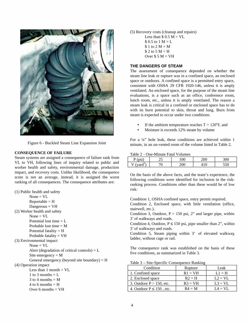
The score on abnormal loads (steam bubble collapse water hammer) reflects the plant experience, where large water hammers caused leakage but not rupture. In one such event, the steam hammer sheared off overhead supports, Figure 5, and buckled an expansion joint, Figure 6, but neither the carbon steel line nor the joint ruptured.
Figure 5 - Rupture of Overhead Steam Line Guide
4
Figure 6 - Buckled Steam Line Expansion Joint
CONSEQUENCE OF FAILURE Steam systems are assigned a consequence of failure rank from VL to VH, following lines of inquiry related to public and worker health and safety, environmental damage, production impact, and recovery costs. Unlike likelihood, the consequence score is not an average, instead, it is assigned the worst ranking of all consequences. The consequence attributes are: (1) Public health and safety None = VL Reportable = H Dangerous = VH (2) Worker health and safety None = VL Potential lost time = L Probable lost time = M Potential fatality = H Probable fatality = VH (3) Environmental impact None = VL Alert (degradation of critical controls) = L Site emergency = M General emergency (beyond site boundary) = H (4) Operation impact Less than 1 month = VL 1 to 3 months = L 3 to 4 months = M 4 to 6 months = H Over 6 months = VH
(5) Recovery costs (cleanup and repairs) Less than $ 0.5 M = VL $ 0.5 to 1 M = L $ 1 to 2 M = M $ 2 to 5 M = H Over $ 5 M = VH THE DANGERS OF STEAM The assessment of consequence depended on whether the steam line leak or rupture was in a confined space, an enclosed space or outdoors. A confined space is a permitted entry space, consistent with OSHA 29 CFR 1920-146, unless it is amply ventilated. An enclosed space, for the purpose of the steam line evaluations, is a space such as an office, conference room, lunch room, etc., unless it is amply ventilated. The reason a steam leak is critical in a confined or enclosed space has to do with its burn potential to skin, throat and lung. Burn from steam is expected to occur under two conditions:
• If the ambient temperature reaches T > 120oF, and • Moisture is exceeds 12% steam by volume
For a ¼” hole leak, these conditions are achieved within 1 minute, in an un-vented room of the volume listed in Table 2. Table 2 - One-Minute Fatal Volumes
P (psi) 25 100 200 300 V (yard3) 70 200 410 550
On the basis of the above facts, and the team’s experience, the following conditions were identified for inclusion in the risk-ranking process. Conditions other than these would be of low risk: Condition 1, OSHA confined space, entry permit required. Condition 2, Enclosed space, with little ventilation (office, stairwell, etc.). Condition 3, Outdoor, P > 150 psi, 2” and larger pipe, within 3’ of walkways and roads. Condition 4, Outdoor, P ≤ 150 psi, pipe smaller than 2”, within 3’ of walkways and roads. Condition 5, Steam piping within 3’ of elevated walkway, ladder, without cage or rail. The consequence rank was established on the basis of these five conditions, as summarized in Table 3. Table 3 – Site-Specific Consequence Ranking
Condition Rupture Leak 1. Confined space R1 = VH L1 = H 2. Enclosed space R2 = H L2 = VL 3. Outdoor P > 150, etc. R3 = VH L3 = VL 4. Outdoor P ≤ 150 , etc. R4 = M L4 = VL

5
5. Within 3ft of elevated R5 = VH L5 = M
RISK RANKING The Likelihood and consequence having been assigned, steam systems can now be plotted on the 5x5 risk matrix, Figure 7. The nomenclature for Figure 7 is described in table 3.
Figure 7 Risk Based Ranking of Steam Systems
RISK INSPECTION PRIORITIES Only one category of steam systems (L1) ended up in the high risk category. These lines were prioritized for mandatory inspection. Steam systems in categories R1, R2, R3 and R5, were also identified for mandatory inspections. The inspection of lower risk categories (L2 to L5, R4) was left to the discretion of each operating unit. CHECK The results of the above risk ranking are quite logical:
• The RBI matrix justifiably differentiates between leaks and breaks, both on likelihood and consequence.
• The matrix highlights the particular risk associated with enclosed and confined spaces, which is well in line with industry experience related to steam fatalities.
• The RBI process was also an opportunity to better quantify the rapid heat-up of an enclosed space, quickly leading to a fatal environment.
EXCEPTIONS Because operational experience is paramount in establishing risk of failure, each operating facility was provided the opportunity to review and approve the risk ranking or submit justification for exceptions, or dissention from the RBI
ranking, to a Management Coordinating team. This did not occur, as each operating facility judged the RBI ranking to be applicable to their operation. As an alternative to the inspection of steam in confined spaces, R1/L1, administrative controls may be put in place to prevent confined space entry where steam lines are in service. That is, R1/L1 locations could be eliminated from inspections if there are adequate controls and protections, or steam is isolated prior to entry into confined spaces. INSPECTION PLANNING Inspection planning consists of the following activities:
• Selection of inspection locations • Selection of inspection technique • Selection of acceptance criteria and method for
fitness-for-service assessment INSPECTION LOCATIONS GUIDE Having identified the priority inspection system attributes, each steam engineer was requested to select a minimum of 10 inspection locations in each facility, in the high risk categories R1/L1, R2, R3 and R5. This resulted in close to 100 inspection locations. The degradation mechanism for wall loss in carbon steel steam lines, in saturated steam service, is erosion corrosion (flow accelerated corrosion FAC). Guidance for selection of inspection points included:
• Areas of prior repairs and known corrosion • Branch connections, at sides and bottom of pipe • Outer arc (extrados) of elbows • Up to 10-diameters downstream of elbows and orifice
plates • Dead legs • At signs of damage to lagging with breach of
insulation • At signs of wetness or leakage • At low points in vertical legs or sagging spans were
condensate could accumulate • Where water and steam mix (popping sounds from
bubble collapse) • Changes in cross section (reducer)
INSPECTION TECHNIQUES The choice of inspection techniques has to address two challenges:
• Because the inspection will take place in winter time, the inspections will take place with steam lines in service.
• Many steam lines date back to the 1950’s and have asbestos insulation.

6
In light of these difficulties, three inspection techniques have been evaluated: standard straight beam ultrasonic testing (pulse echo), pulsed eddy current, Figure 8, and digital radiography, Figure 9. Because the lines had to be inspected while in-service, avoiding removal of insulation, pulsed eddy current and digital radiography were the preferred techniques. Pulsed eddy current inspections had been contracted two years earlier, with good results. This time, the inspection technique selected was digital radiography. Figure 9 is a digital radiography of a 1” schedule 80 steam pipe, it shows longitudinal striations as the flow enters the reducer section, and marked wall thinning in the weld itself.
Figure 8 - Pulsed Eddy Current Through-Insulation
Figure 9 - Digital Radiography of Reducer INSPECTION ACCEPTANCE CRITERIA Prior to inspection, it is essential to define acceptance criteria. The design basis for the site piping systems is ASME B31.1 for steam production and distribution, and ASME B31.3 for steam use in facilities. A three level acceptance criterion was defined in terms of minimum wall thickness: Green, steam line acceptable for continued service, re-inspect in 5 years, if
tmm > tmin + 50 mils, and tmm > 20% tnom + 50 mils
The Green criterion above is based on (a) compliance with the ASME B31 required minimum wall, (b) providing a future corrosion allowance of 10 mpy x 5 years, till the next inspection in 5 years, and (c) assuring that there is no excessive wall loss, not to exceed 80% of the wall. The last criterion (c) is consistent with B31G[7] for oil and gas pipelines, and is similar in concept to API 579[8] fitness-for-service rules for general wall thinning.
Yellow, detailed evaluatio n required within 60 days, if
tmm > tmin, and tmm > 20% tnom
The yellow criterion above is based on (a) compliance with the ASME B31 required minimum wall, without a future corrosion allowance, and (b) assuring that there is no excessive wall loss,

7
not to exceed 80% of the wall. This condition cannot be left as-is for 5 more years of service, it needs to be evaluated and resolved within 60 days.
Red, immediate assessment, safeguarding and shutdown if necessary, if
tmm below yellow
tmm = minimum measured wall thickness tmin = minimum wall thickness required by ASME B31 code tnom = nominal wall thickness, in For more detailed assessments, in particular for the evaluation of yellow and green readings, the rules of API 579, may be applied to evaluate the fitness-for-service and remaining life of the corroded steam line. CONCLUSION A risk-based inspection (RBI) program was developed and is being implemented to prevent steam accidents that could jeopardize safety or production. Steam systems were ranked on the basis of likelihood and consequence of failure. Inspection techniques and acceptance criteria were developed and will be applied to inspect utility and process steam lines, site-wide.
REFERENCES 1. API RP 580, Risk-Based Inspection, American Petroleum Institute, Washington, DC. 2. ASME B31.1, Power Piping, American Society of Mechanical Engineers, New York, NY. 3. ASME B31.3, Process Piping, American Society of Mechanical Engineers, New York, NY. 4. API 570, Piping Inspection Code Inspection, Repair, Alteration, and Rerating of In-Service Piping Systems, American Petroleum Institute, Washington, DC. 5. NBIC ANSI-NB-23, National Board of Inspection Code, National Board, Columbus, OH. 6. API Publ. 581, Risk-Based Inspection Base Resource Document, American Petroleum Institute, Washington, DC. 7. ASME B31G, Manual for Determining the Remaining Strength of Corroded Pipelines a Supplement to ASME B31 Code for Pressure Piping, American Society of Mechanical Engineers, New York, NY. 8. API RP 579, Fitness-for-Service, American Petroleum Institute, Washington, DC.