thirty years of development of silencers for flashing ... · pdf filesilencers for flashing...
TRANSCRIPT
Proceedings World Geothermal Congress 2010 Bali, Indonesia, 25-29 April 2010
1
Silencers for Flashing Geothermal Brine, Thirty Years of Experimenting
Geir Thorolfsson
Brekkustigur 36, Reykjanesbaer, ICELAND
Keywords: Geothermal brine, silencers.
ABSTRACT
The process of flashing geothermal brine at atmospheric pressure produces extremely loud noise level. In dealing with this problem, Hitaveita Suðurnesja has operated various types of silencers; the story goes back to the year 1976. In this paper the silencers will be described, emphasizing advantages, disadvantages, and problem solutions. In brine silencers the main problems relate to scaling and corrosion. Additionally, eliminating airborne brine drops, containing silica, is important because the silica opaquefies glass windows in the neighborhood and destroys glossy lacquer on cars. Design methods are described and practical solutions presented. It is important to emphasize that this development is not completed, but an ongoing process. The silencers described here are: round-centrifugal-tangential-inlet silencers, lateral-under-water-injection silencers, horizontal-over-water-inlet silencers, vertical-inlet (in a pool of brine) silencers. Control valves are usually adjacent to the silencer. Control valves, for controlling brine, tend to get stuck because of silica scaling. Some improvements are suggested. The main construction material of silencers is concrete. However, thermal stress causes cracking of the concrete. Different types of concrete and different reinforcements, such as stainless steel fibers and epoxy-coated rebar have been tried and will be described here.
1. INTRODUCTION
Hitaveita Suðurnesja (HS) owns and operates power plants at two geothermal systems, the Svartsengi and the Reykjanes. The first part of the Svartsengi plant was commissioned in 1977. The Svartsengi plant has been expanded in stages, currently with installed power of 74 MW and 150 MJ/s district heating power. The 2 x 50 MW Reykjanes plant was commissioned in 2006.
The literature is rather limited regarding the actual construction of geothermal silencers. The current paper is a try to improve on the subject.
When reducing the pressure of hot geothermal brine, steam- brine mixture is formed and the mixture attains sonic velocity.
Main purpose of silencers is, of course, to reduce noise level in the environment. Additionally ground fog should be avoided and airborne brine drops containing dissolved elements eliminated.
The first of silencer design for HS was completed in 1976. The silencer was for flashing flow from wells 4 and 5 in the “preliminary” heat-exchange station in Svartsengi. The design was based on a picture of a well silencer in Krafla. This first HS silencer had a brine-filled chamber where the pipe from the well ended. A separating section with a short chimney completed the flow path.
Construction material of silencers is mainly concrete. The main problem here is cracking of the concrete. Different types of concrete and different reinforcements, such as stainless steel fibers and epoxy-coated rebar have been tried and will be described here.
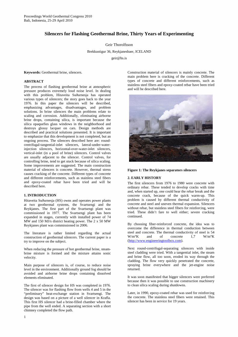
Figure 1: The Reykjanes separators silencers
2. EARLY HISTORY
The first silencers from 1976 to 1980 were concrete with ordinary rebar. These tended to develop cracks with time and, when started up, one could hear the rebar break and the concrete crack, because of the quick warm-up. This problem is caused by different thermal conductivity of concrete and steel and uneven thermal expansion. Silencers without rebar, but stainless steel fibers for reinforcing, were tried. These didn’t fare to well either; severe cracking continued.
By choosing fiber-reinforced concrete, the idea was to overcome the difference in thermal conduction between steel and concrete. The thermal conductivity of steel is 54 W/m°K and of concrete 1,7 W/m°K (http://www.engineeringtoolbox.com).
Next round-centrifugal-separating silencers with inside steel cladding were tried. With a tangential inlet, the steam and brine flow, all too soon, eroded its way through the cladding. The flow very quickly penetrated the concrete, spraying brine everywhere and the jet-engine noise returned.
It was soon manifested that bigger silencers were preferred because then it was possible to use construction machinery to clean silica scaling during shutdowns.
Later, in 1990, epoxy-coated rebar was used for reinforcing the concrete. The stainless steel fibers were retained. This silencer has been in service for 19 years.

Thorolfsson
2
2.1 Control valves
The silica scaling (Fig. 2) in the brine pipelines begins as the temperature is lowered below 150°C in Svartsengi and 200°C in the Reykjanes plant (Thorolfsson, 2005). The pressure in the separators and brine pipes is kept as high as necessary to prevent silica scaling. Scaling problems, however, are prominent in the level-control valves for the brine in the separators. The level-control valves reduce the pressure to atmospheric before the brine enters the silencers. The valves were prone to get stuck and, when they did not stick, the valve stems wore down very quickly. Both problems were solved by modifying the control valves. In the Svartsengi plant, hot water (deaerated) is injected into the valve stuffing box at a pressure of about 9 bars. However, in Reykjanes high pressure condensate at 22 bars is used. The high pressure water, or condensate, drives the brine together with silica particles out of the bearings.
Figure 2: Silica scaling in a brine injection pipe after one year operation.
Figure 3: Silencer for Reykjanes Power Plant under construction, showing the basin and brine injecting pipes
3. RECENT DEVELOPMENTS AND FUNCTIONAL ANALYSIS
Currently the HS silencers are constructed from high-strength concrete with epoxy coated rebar. The silencers are actually large basins with aluminum tops, as shown in Fig. 1, 3, and 4. The basin serves the function of silencing, that is, reducing the noise level. The aluminum top serves as a separator, separating the brine drops and the steam. By this procedure the brine carry-over is minimized. Furthermore the aluminum chimneys lift the vapor plume, eliminating ground fog. The brine in the basin boils vigorously, just like water boiling in a casserole on a stove. To continue with the analogy, the aluminum top is like a lid with vent holes.
3.1 The basins
The basin shown in Fig. 3 is for a Reykjanes plant silencer. This basins were designed to have a maximum throughflow of 300 kg/s brine, flashed from 18 bar, 210°C. A heat balance in these circumstances gives 236 kg/s brine and 64 kg/s steam.
Figure 4: A perspective showing pipe and basin arrangement in Reykjanes silencers.
3.2 The aluminum tops
The top serves the purpose of a droplet separator. It directs the flow of steam towards the exhaust stacks and, at the same time, slows down the steam flow, facilitating the falling of the drops back to the basin. The basin must be covered. To see why, make the following experiment: Pour your favorite soda in a glass until 2 cm from the rim. Now take off your glasses and put them over the glass for just a few seconds. Now inspect your glasses. You will discover small drops from the soda carried with the carbon dioxide “boiling” off. So now you have “carryover” on your glasses. The carryover from the basin must not be allowed into the environment (Fig. 5) because dissolved elements in the drops are corrosive, opaquefy glass, destroy car paint and can be detrimental to vegetation.
3.3 Design tricks
The design of a silencer is, in many ways, similar to the design of a horizontal separator. When designing horizontal separators the following steam velocities have been found to work satisfactorily: Went stack, 10 m/s; steam chamber ahead of went stacks, 3 m/s. The length of the silencer must be enough for a 1 mm diameter brine drop to descend to the water surface (Gerunda 1981).
Thorolfsson
3
Figure 5: Here we see a very unfortunate result of a silencer design. Big, salty, silica laden drops are thrown out of the silencer steam exhaust stack.
The silencers described above are usually called “separator” silencers, used for the flashing brine from separators. Other types are used when testing wells. Those are called wellhead silencers (Fig. 6) and will be described in the following.
Figure 6: Wellhead vertical drum silencer (from Dr. Bjarni Pálsson, 2007) (staff.unak.is/not/hreidar/MAU1103/Djupboranir.ppt)
4. WELLHEAD SILENCERS
The Wairakei silencer (Fig. 7) has never been copied in detail in Iceland. Many variations have been made. The unit in Fig. 6, was designed 30 years ago and is a rather ineffective unit. It is noisy at high enthalpies and has a lot of carry over at high brine loads. Geothermal power plants in Iceland, other than HS, use this type at each wellhead, when the well is being tested or kept alive while not in use. HS made an improvement during a well work over in Svartsengi in 1990. Then a lid with a chimney was put on one unit (Fig 8). A considerable further improvement was made when HS made a horizontal steel separator silencer for well testing (Fig. 9). This silencer enables measuring the steam flowrate directly, using a steam meter in the chimney; a major advance in determining the enthalpy of a well.
Figure 7: The Wairakei silencer, from Armstead 1980, UNU-GTP (http://www.os.is/Apps/WebObjects/Orkustofnun.woa/swdocument/32698/Armstead02.pdf)
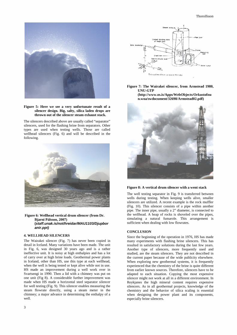
Figure 8: A vertical drum silencer with a went stack
The well testing separator in Fig. 9 is transferred between wells during testing. When keeping wells alive, smaller silencers are utilized. A recent example is the rock muffler (Fig. 10). This silencer consists of a pipe within another pipe. The inner pipe, usually a 2” diameter, is connected to the wellhead. A heap of rocks is shoveled over the pipes, simulating a natural fumarole. This arrangement is sufficient when dealing with low flowrates.
CONCLUSION
Since the beginning of the operation in 1976, HS has made many experiments with flashing brine silencers. This has resulted in satisfactory solutions during the last few years. Another type of silencers, more frequently used and studied, are the steam silencers. They are not described in the current paper because of the wide publicity elsewhere. When exploring new geothermal systems, it is frequently experienced that the chemistry of the brine is quite different from earlier known sources. Therefore, silencers have to be adapted to each situation. Copying the most expensive silencer might not work at all in a different environment. In Reykjanes the high mineral content requires expensive silencers. As in all geothermal projects, knowledge of the chemistry and the behavior of silica scaling is essential when designing the power plant and its components, especially brine silencers.

Thorolfsson
4
Figure 9: The horizontal separator/silencer for well testing
Figure 10: A rock muffler in a fumarole disguise
REFERENCES
Thorolfsson, G.: Maintenance History of a Geothermal Plant: Svartsengi Iceland, Proceedings, World Geothermal Congress 2005, Antalya, Turkey, 24-29 April 2005
Gerunda, A.: How to size liquid-vapor separators, Chemical Engineering, May 4, 1981, 81 - 84.