thin films for superconducting cavities
DESCRIPTION
Thin Films for Superconducting Cavities. HZB. Outline. Introduction to Superconducting Cavities The Quadrupole Resonator Commissioning Outlook. Basics of RF Cavities. Acceleration of charged particles using a radio frequency field - PowerPoint PPT PresentationTRANSCRIPT

Thin Films for Superconducting Cavities
HZB

2
Outline
• Introduction to Superconducting Cavities• The Quadrupole Resonator• Commissioning• Outlook

3
Basics of RF Cavities
• Acceleration of charged particles using a radio frequency field
• There are normal conducting and superconducting (sc) cavities
• Qnc ≈ 105 vs. Qsc ≈ 1010
• The needed power for operation is about a factor of 200 less than for superconducting cavities
4
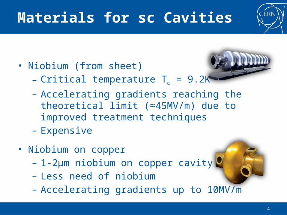
Materials for sc Cavities
• Niobium (from sheet)– Critical temperature Tc = 9.2K– Accelerating gradients reaching the theoretical limit
(≈45MV/m) due to improved treatment techniques– Expensive
• Niobium on copper– 1-2μm niobium on copper cavity– Less need of niobium– Accelerating gradients up to 10MV/m

5
Where can we improve?
Understanding the dominant loss mechanisms in niobium
Reducing losses
Improving the performance of niobium films
Reducing material costs
Finding new materials ?

6
How can we improve?
• Power consumption in a superconducting cavity is proportional to its surface resistance RS
• RS shows a complex behavior on external parameters, such as temperature, frequency, magnetic and electric field
),,,(Sc EBTfRP
Systematic studies on cavities are no option

7
The Quadrupole Resonator
361
mm
• The Quadrupole Resonator enables RF characterization of small, flat samples over a wide parameter range
• Samples of 75mm diameter are welded to a niobium cylinder with flange so that they can be mounted to the host cavity
8
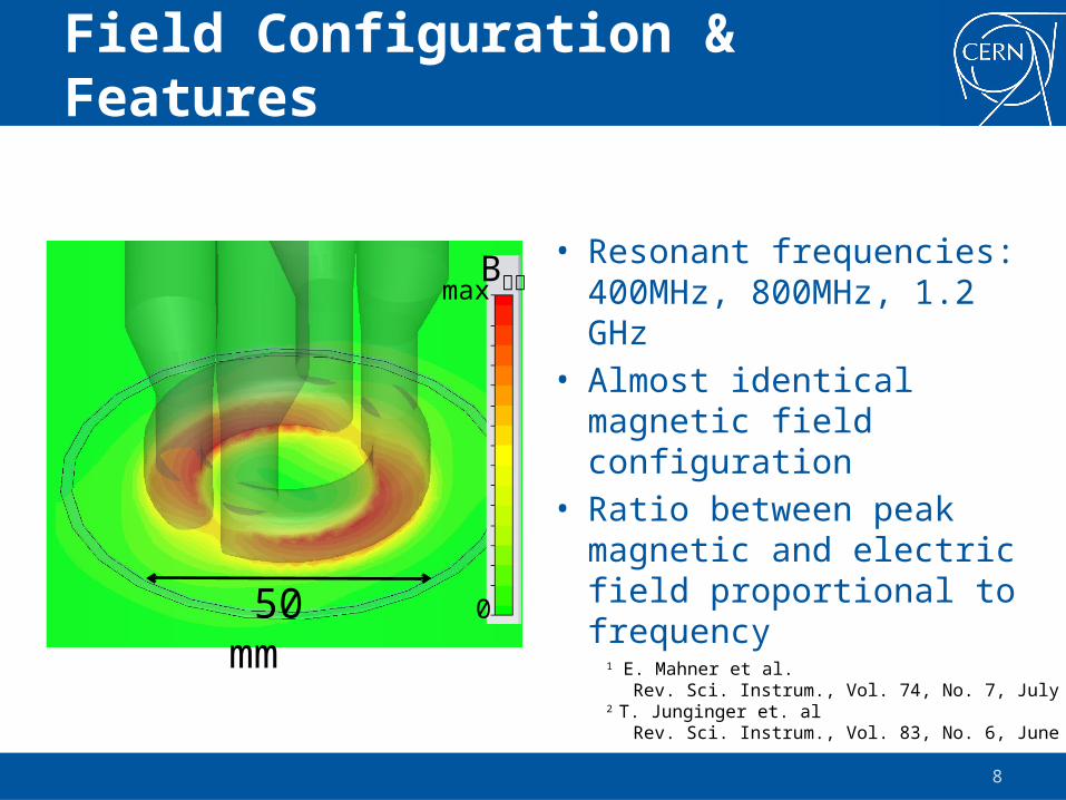
Field Configuration & Features
• Resonant frequencies: 400MHz, 800MHz, 1.2 GHz
• Almost identical magnetic field configuration
• Ratio between peak magnetic and electric field proportional to frequency
B ׀׀
0
max
50 mm1 E. Mahner et al.
Rev. Sci. Instrum., Vol. 74, No. 7, July 20032 T. Junginger et. al
Rev. Sci. Instrum., Vol. 83, No. 6, June 2012

9
DC Heater
Quadrupole Resonator Thermometry Chamber
Heat Flow
The Calorimetric Technique
• Measuring the temperature on the sample surface
• Precise Calorimetric measurements over wide temperature range
TemperatureSensorsSample Surface

10
time
Temperature
Bath Temperature
Temperatureof Interest
P DC,
1
P DC,
2P RF
Power
DC on RF on≈60 s ≈40 s
dSHRPPPSample
SurfaceDCDCRF 22,1, 21
dSH
PPR
Sample
DCDCSurface
2
2,1, )(2
TemperatureSensors
DC Heater
Heat Flow
The Calorimetric Technique
Measured directly
• Measurement of transmitted power Pt
• Pt=c∫H2ds, c from computer code

11
Imperfect Meissner Effect
Meissner effect
Trapped magnetic flux

12
Flux Trapping in the Quadrupole Resonator
Sample
DC Coil

13
Flux Trapping in the Quadrupole Resonator
DC Coil�⃗�

14
First test with trapped flux
• Bulk niobium sample• Reactor grade, RRR • Standard BCP, no bake out

15
RS(B) at 400MHz, 2-4K
• Convex curve for • Concave curve for • Different loss
mechanisms dominant

16
Trapped Flux at 400MHz and 4K

17
Outlook
• MgB2 from Superconductor Technologies, Inc.– Tc = 39K, Bc up to 1T
– expected: Eacc > 75MV/m, RBCS(4K,500MHz) = 2.5nΩ
• HiPIMS: Nb/Cu from CERN and Berkeley– Dense film, low cost, but competitive to bulk Nb?
• ECR: Nb/Cu from Jlab– High RRR, low cost, but competitive to bulk Nb?
