thickness planer with anti-kickback … when changing attachments, blades, bits, cutters, etc., all...
TRANSCRIPT

RAP1500GTHICKNESS PLANER WITH ANTI-KICKBACKOPERATOR’S MANUAL

2
DESCRIPTION
1. Top guard2. Cutterhead height adjustment crank handle3. Depth of cut scale4. Power switch5. Overload switch6. Table extension7. Base lock screws8. Feet9. Elevation knob lock screw10. Push stick11. Blade setting gauge12. Hex keys13. Open end wrench14. Plastic pointer15. Dust chute16. Hexagonal socket head cap screws17. Forcing screws18. Blade setting gauge19. Lock bar20. Lock screws21. Blades22. Spring23. Allen screws24. Height adjustment nut

3
Fig. 1
6
5
4
21
3
Fig. 4
7
128
29
13
5 mm 4 mm
11
10
Fig. 3Fig. 2

4
Fig. 11 Fig. 12
Fig. 5 Fig. 6
Fig. 8
14
2
18
19
20
22
3
50.8
50.8
Mountinghole
Planerbasehole
m8 screw
2-Ø9 Ø9
Ø1515
Fig. 7
Fig. 9
21
17
4
5
Fig. 10
15
16

5
Fig. 13
Fig. 16
Fig. 17
24
Fig. 14
2
Fig. 15
Fig. 18 Fig. 19
135º
34 mm
33 mm 33 mm
5 mm
3 mm
100 mm
120º
70 mm
100 mm
15 mm30 mm
20 mm
18
19
20
22
21
23
ø 50mmø 50mm

6
Important!
It is essential that you read the instructions in this manual before operating this machine.
Subject to technical modifications.

7
both hands to operate the tool. ■ Do not overreach. Keep proper footing and balance
at all times. ■ Maintain tools with care. Keep tools sharp and clean
for better and safer performance. Follow instructions for lubricating and changing accessories.
■ Store idle tools. When not in use, tools should be stored in a dry locked-up place, out of reach of children.
■ Disconnect tools. When not in use, before servicing, or when changing attachments, blades, bits, cutters, etc., all tools should be disconnected from the power source.
■ Avoid accidental starting. Be sure switch is off when plugging in any tool.
■ Use recommended accessories. Consult the operator’s manual for recommended accessories. The use of improper accessories may result in injury.
■ Never stand on tool. Serious injury could occur if the tool is tipped.
■ Check for damaged parts. Before further use of the tool, a guard or other part that is damaged should be carefully checked to determine that it will operate properly and perform its intended function. Check for alignment of moving parts, binding of moving parts, breakage of parts, mounting and any other conditions that may affect its operation. A guard or other part that is damaged must be properly repaired or replaced by an authorised service centre to avoid risk of personal injury.
■ Use the right direction of feed. Feed work into a blade, cutter, or sanding spindle against the direction or rotation of the blade, cutter, or sanding spindle only.
■ Never leave tool running unattended. Turn the power off. Don’t leave tool until it comes to a complete stop.
■ Protect your lungs. Wear a face or dust mask if the operation is dusty.
■ Protect your hearing. Wear hearing protection during extended periods of operation.
■ Do not abuse cord. Never carry tool by the cord or yank it to disconnect from receptacle. Keep cord from heat, oil, and sharp edges.
■ Use outdoor extension cords. When tool is used outdoors, use only extension cords with approved ground connection that are intended for use outdoors and so marked.
■ Stay alert and exercise control. Watch what you are doing and use common sense. Do not operate tool when you are tired. Do not rush.
■ Do not use tool if switch does not turn it on and off. Have defective switches replaced by an authorised service centre.
■ Always turn switch off before disconnecting it to
GENERAL POWER TOOL SAFETY WARNINGS
WARNINGWhen using electric tools, basic safety precautions should always be followed to reduce the risk of fire, electric shock and personal injury.
Read all these instructions before attempting to operate this product and save these instructions.
■ Know your power tool. Read the operator’s manual carefully. Learn the applications and limitations as well as the specific potential hazards related to this tool.
■ Guard against electrical shock by preventing body contact with grounded surfaces. For example: pipes, radiators, ranges and refrigerator enclosures.
■ Keep guards in place and in good working order. ■ Remove adjusting keys and wrenches. Form a habit
of checking to see that keys and adjusting wrenches are removed from tool before turning it on.
■ Keep work area clean. Cluttered areas and benches invite accidents. Do not leave tools or pieces of wood on the tool while it is in operation.
■ Do not use in dangerous environments. Do not use power tools in damp or wet locations or expose it to rain. Keep the work area well lit. Do not use the tool in the presence of flammable liquids or gases.
■ Keep children and visitors away. All visitors should wear safety glasses and be kept a safe distance from work area. Do not let visitors contact tool or extension cord while operating. Children should be supervised to ensure that they do not play with the tool.
■ This product is not intended for use by persons (including children) with reduced physical, sensory or mental capabilities, or lack of experience and knowledge, unless they have been given supervision or instruction concerning use of the product by a person responsible for their safety.
■ Make workshop childproof with padlocks, master switches, or by removing starter keys.
■ Don’t force the tool. It will do the job better and safer at the feed rate for which it was designed.
■ Use the right tool. Do not force the tool or attachment to do a job for which it was not designed.
■ Dress properly. Do not wear loose clothing, gloves, neckties, or jewellery that can get caught and draw you into moving parts. Rubber gloves and nonskid footwear are recommended when working outdoors. Also wear protective hair covering to contain long hair.
■ Always wear safety glasses with side shields. Everyday eyeglasses have only impact-resistant lenses; they are not safety glasses.
■ Secure work. Use clamps or a vice to hold work when practical. It is safer than using your hand and frees

8
avoid accidental starting. ■ Never use in an explosive atmosphere. Normal
sparking of the motor could ignite fumes. ■ Inspect tool cords periodically. If damaged, have
them repaired by a qualified service technician at an authorised service facility. If repair or replacement of the electric cord or plug is necessary, do not connect the equipment-grounding conductor to a live terminal. Repair or replace a damaged or worn cord immediately. Stay constantly aware of cord location and keep it well away from the rotating blade.
■ Keep tool dry, clean, and free from oil and grease. Always use a clean cloth when cleaning. Never use brake fluids, gasoline, petroleum-based products, or any solvents to clean tool.
■ Never start a tool when any rotating component is in contact with the workpiece.
■ Do not operate a tool while under the influence of drugs, alcohol, or any medication.
■ When servicing, use only identical replacement parts. Use of any other parts may create a hazard or cause product damage.
■ Use only recommended accessories listed in this manual or addendums. Use of accessories that are not listed may cause the risk of personal injury. Instructions for safe use of accessories are included with the accessory.
PLANER SAFETY WARNINGS ■ Always wear eye protection when operating the
machine. ■ Check to make sure all holding screws are tight before
starting machine. ■ Always stop the motor and disconnect from the power
source before making any adjustments. ■ Be sure all guards are in place before operation. ■ Read operator's manual thoroughly and familiarise
yourself with the machine before operation. ■ Do not force work through the machine. Allow the
planer to apply the proper feed rate. ■ Check feed rollers occasionally to be sure sawdust
and chips are not lodged between any components. If rollers are not seated firmly, the feed rolls will not hold timber firmly against the bed, allowing kickback.
■ Check and make sure the roller tables are on the same plane with the work table when planing wood, and the rollers can rotate freely when planing long workpieces.
■ Only plane wood boards. ■ Use sound timber, with no loose knots and as few tight
knots as possible. ■ Never stand directly in line with either the infeed or
outfeed sides. Always stand off to one side of the machine.
■ Make sure the workpiece is free of nails, screws, stones and other foreign objects which could damage the blades.
■ Make sure the blades are attached correctly as described in the instructions.
■ Use caution when handling the blades and cutterhead assembly. The blades are sharp and can easily cut your hand.
■ Allow the cutterhead to reach full speed before using. ■ Use the push stick instead of your hands to push the
workpiece when its end approaches the blades. The push stick should be stored on the work table when not in use.
WARNINGNever conduct the following operations:
■ Stopped work (i.e., any cut which does not involve the full length of the workpiece)
■ Planing recesses, tenons or moulds ■ Planing badly bowed wood with inadequate contact
with the infeed table
ANTI-KICKBACK PAWLSSee figure 2.
■ An anti-kickback pawl is a device which, when properly installed and maintained, is designed to stop the workpiece from being kicked back toward the front of the blade during a planer operation.
AVOIDING KICKBACK ■ Always use the correct blade depth setting.
Inspect the work for knots or nails before beginning a cut. Knock out any loose knots with a hammer. Never cut into a loose knot or nail.
■ Always use clean, sharp, and properly-set blades. ■ Never use planer with dull blades. ■ To avoid pinching the blade, support the work properly
before beginning a planer operation. ■ When planing use steady, even pressure. Never force
the planer. ■ Do not plane wet or warped timber. ■ Always hold your workpiece firmly with both hands,
keep your body in a balanced position to be ready to resist kickback. Never stand directly in line with timber.

9
■ Choose two pieces of wood according to the sizes shown in the figure. Mount the planer onto the wood surface.
■ Use the four base lock screws (supplied) to mount the planer base onto the wood.
STOCK RESTSee figure 7.
■ The stock rest on the top of the planer provides convenient handling of stock for consecutive cutting operations. Stock placed on the top of the machine can be easily pulled to the operator for planing.
OPERATION
ON / OFF SWITCHSee figure 8.
■ Open the red switch cover to expose the ON / OFF switch.
■ To turn on the planer, push the I button. To turn off, push the O button.
■ After operation, close the red switch cover to avoid accidental starting.
WARNINGAlways be sure the switch is in the OFF position before connecting the planer to the power source.
CIRCUIT OVERLOAD SWITCHSee figure 8.
■ The machine is provided with an overload switch for overload protection. If an overload occurs, the switch will pop out. If this happens, wait several minutes and press the switch to reset the machine.
ADJUSTING DEPTH OF CUTSee figure 9.
WARNINGNever plane more than 3 mm in one pass and never attempt to plane a board under 127 mm (5") in length. Always wear a protective face shield.
■ To adjust the depth of cut, turn the cutterhead height adjustment crank handle in the directions marked on top of the planer. The depth of cut adjustment can be read from the depth of cut scale. The adjustment gradation is 1.6 mm per revolution of the crank.
■ Always start your work by making a light planing cut. The depth of cut on subsequent passes may be increased by up to 3 mm, but remember that a light cut creates a finer finish than a heavier cut.
SPECIFICATIONS
Product SpecificationsInput 220-240 V , 50 Hz
1,500 W, 6.25 AmpNo load speed 9,000 min-1
Min. planing length 127 mm
Max. planing width 318 mm
Planing height 7 - 153 mm
Max. planing depth per pass 3 mm
Feeding speed 8 m/min
Weight 30.5 - 32 kg
LOOSE PART LIST
Item Description Qty
7 Base lock screws 4
8 Feet 4
9 Elevation knob lock screw 1
10 Push stick 1
11 Blade setting gauge 1
12 Hex keys 2
13 Open end wrench 1
INTENDED USE ■ Planing wood
Do not use this product in any other way other than those stated for intended use.
ASSEMBLY
MOVING THE PLANERSee figure 3.
■ The planer can be carried using the handles on both sides of the frame. Make sure the table extensions are closed before moving the planer.
INSTALLING FEET ■ Attach the feet to the corners at the bottom of the
planer.
MOUNTING THE PLANER ONTO A WOOD BASESee figures 5-6.
■ When the planer is not mounted on a planer stand, it is suggested that it be mounted onto two pieces of timber. This will ensure maximum stability.

10
"SETTING THE BLADE HEIGHT". The blade height must be reset every time the blades are taken out for any reason.
■ Be sure to replace the dust chute after blades are installed.
SETTING THE BLADE HEIGHTSee figure 13-14.
■ To obtain a blade projection of 1.1 mm, place the blade setting gauge on the cutterhead with both guides resting firmly against the blade.
■ Loosen the assembly by turning the seven forcing screws clockwise with an open end wrench.
■ When the blade is pressed to the required height by guides on the gauge, retighten the assembly by turning the forcing screws counter clockwise. Make sure all seven forcing screws are tightened securely.
WARNINGThe blade edge is very susceptible to chipping. Use caution when handling the gauge near the blades to avoid damaging them.
WARNINGThe assembly must be tightened securely to prevent accidents during planing.
CONNECTING A DUST COLLECTION SYSTEMSee figure 19.The dust produced when using this tool may be harmful to health. Use a dust absorption system and remove deposited dust thoroughly, e.g., with a vacuum cleaner.To connect a dust collection system:
■ Unplug the tool. ■ Connect the nozzle of the dust collection system to
the dust chute.Clean the hose of the dust collection system frequently to avoid the accumulation of dust.
ADJUSTMENT
MAKING THE CUTTERHEAD AND WORK TABLE PARALLELSee figures 15-18.Plane a workpiece and measure the thickness after the cut. If the thicknesses are different on both sides of the workpiece, perform the following:Adjust the cutter shaft and the worktable so they are parallel. The tools used for checking are shown in figure 15. Use hardwood to make a tool gauge block according to the size shown in the figure. Make the adjustments as
■ The thickness of timber running through the planer is controlled by the distance you adjust the cutting blade from the table.• Do not plane timber that is less than 7 mm thick.• Do not plane timber that is thicker than 153 mm
(6").
ADJUSTING THE DEPTH OF CUT SCALESee figure 9.For the safe operation of your planer, it is very important that the depth of cut scale reads accurately. To adjust the depth of cut scale, follow the steps below:
■ Feed a board for planing.Compare the measured thickness of the board to the reading on the depth of cut scale.
■ If the reading on the depth of cut scale is incorrect, loosen the screw which tightens the plastic pointer and adjust accordingly.
■ When you have properly adjusted the depth of cut scale, test the reading by planing a piece of scrap timber. After planing, measure the planed thickness and double check it against the scale reading. The two measurements should be the same. Re-adjust the depth of cut scale to read the planed thickness if necessary.
REMOVING THE PLANER BLADESSee figure 10-12.To remove the planer blades, follow the steps below:
WARNINGUnplug your planer from the power source before removing the planer blades.
■ Remove the dust chute by removing the four hexagonal socket head cap screws on it.
■ Loosen the lock bar and blade by turning the forcing screws clockwise. The blades are spring loaded, and will push out when the assembly is loosened.
■ Take out the blade, and then the blade lock bar.
INSTALLING / REPLACING THE PLANER BLADESSee figure 12.To install the planer blades, follow the steps below:
■ Remove the blades according to the instructions in "REMOVING THE PLANER BLADES".
■ Clean away all debris from the planer cutterhead. ■ Fit the blade lock bar into the slot on the cutterhead. ■ Fit the blade into the slot on the cutterhead, and
tighten the lock bar blade assembly by turning the forcing screws counter clockwise. Make sure the blade is facing the correct direction and is centred in the slot.
■ Set the blade heights according to the instructions in

11
screws. ■ The bearings on the cutterhead are factory lubricated
and sealed. They require no further attention.
PERIODIC MAINTENANCE ■ The build-up of sawdust and other debris can cause
your machine to plane inaccurately. Periodic cleaning is mandatory for precision planing and is highly recommended.
■ Close fitting parts, such as the lockbars and the planer cutterhead slots, should be cleaned with a brush; remove clinging foreign matters. Then replace all parts in their respective positions slightly dampened with oil.
■ Remove resin and other accumulations from feed rollers and table with a non-flamable solvent.
ENVIRONMENTAL PROTECTION
Recycle raw materials instead of disposing of as waste. The machine, accessories and packaging should be sorted for environmental-friendly recycling.
SYMBOL
Safety alert
Regulatory Compliance Mark (RCM). Product meets applicable regulatory requirements.
Please read the instructions carefully before starting the product.
Class II tool, double insulation
Wear ear protection
Always wear eye protection
Waste electrical products should not be disposed of with household waste. Please recycle where facilities exist. Check with your Local Authority or retailer for recycling advice.
per the following procedures. ■ Remove the height adjustment crank handle and
both top and side covers by removing allen screws to expose the height adjustment lock nuts.
■ Loosen the adjustment lock nuts. ■ Adjust the height adjustment lock nuts up or down as
required to suit the gauge block. ■ When the desired height setting is reached, tighten the
lock nuts in position. ■ Reassemble side and top covers and replace the
height adjustment crank handle.NOTE: Remove gauge block before starting machine.Thickness planing is the sizing of the material to a desired thickness, while creating a smooth surface parallel to the opposite side of the board.The art of thickness planing consists mainly of using good judgement about the depth of cut in various situations. You must take into account:1. The width of the timber2. The hardness of the timber3. The dampness of the timber4. The straightness of the board5. The grain direction6. The grain structureHow these factors can affect the quality of the work can only be learned through experience. Whenever working with a new type of wood, or one with unusual problems, always make test cuts on scrap material prior to working on the actual piece.
FOR ADDITIONAL PLANINGIf additional planing is needed to obtain the desired thickness of finish, hand crank the cutterhead no more than 3 mm (at any given time) and complete another pass.
WARNINGNever plane more than 3 mm in one pass and never attempt to plane a board under 127 mm (5") in length. Always wear a protective face shield.
MAINTENANCE
LUBRICATION ■ The recommended lubrication for roller chains used in
medium to low operation is to simply wipe the chain clean. When there is an excess build-up of dust or wood shavings, etc., coat the chain with a light film of oil but never pour the oil directly on the chain. Over-oiling tends to hasten the collection of dust and woodshavings and works them into members of the chain leading to increased wear and premature replacement. This applies to the speed reduction and height adjustment chains as well as the elevation
12
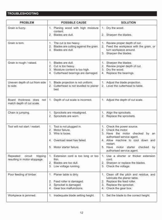
TROUBLESHOOTING
PROBLEM POSSIBLE CAUSE SOLUTION
Grain is fuzzy. 1. Planing wood with high moisture content.
2. Blades are dull.
1. Dry the wood.
2. Sharpen the blades.
Grain is torn. 1. The cut is too heavy.2. Blades are cutting against the grain.3. Blades are dull.
1. Review proper depth of cut.2. Feed the workpiece with the grain, or
turn workpiece around.3. Sharpen the blades.
Grain is rough / raised. 1. Blades are dull.2. Cut is too heavy.3. Moisture content is too high.4. Cutterhead bearings are damaged.
1. Sharpen the blades.2. Review proper depth of cut.3. Dry the wood.4. Replace the bearings.
Uneven depth of cut from side to side.
1. Blade projection is not uniform.2. Cutterhead is not levelled to planer
bed.
1. Adjust the blade projection.2. Level the cutterhead to table.
Board thickness does not match depth of cut scale.
1. Depth of cut scale is incorrect. 1. Adjust the depth of cut scale.
Chain is jumping. 1. Sprockets are misaligned.2. Sprockets are worn.
1. Align the sprockets.2. Replace the sprockets.
Tool will not start / restart. 1. Tool is not plugged in.2. Motor failure.3. Wire is loose.
4. Overload reset has failed.
5. Motor starter failure.
1. Check the power source.2. Check the motor.3. Have the motor checked by an
authorised service agent.4. Allow machine to cool down and
restart.5. Have motor starter checked by
authorised service agent.
Repeated circuit tripping resulting in motor stoppage.
1. Extension cord is too long or too thin.
2. Blades are too dull.3. Low voltage running.
1. Use a shorter or thicker extension cord.
2. Sharpen or replace the blades.3. Check the voltage.
Poor feeding of timber. 1. Planer table is dirty.
2. Feed roller is damaged.3. Sprocket is damaged.4. Gear box malfunctions.
1. Clean off the pitch and residue, and lubricate the planer table.
2. Replace the feed roller.3. Replace the sprocket.4. Check the gear box.
Workpiece is jammed. 1. Inadequate blade setting height. 1. Set the blade to the correct height.

Techtronic Industries (Australia) Pty. Ltd.Level 1, 660 Doncaster RoadDoncaster, VIC 3108, Australia
Techtronic Industries New Zealand Ltd.18-26 Amelia Earhart AvenueMangere, Auckland 2022, New Zealand