theses and dissertations thesis collection · tablecfcontents i. introduction 12 a.background 12...
TRANSCRIPT

Calhoun: The NPS Institutional Archive
Theses and Dissertations Thesis Collection
1982
Analysis of the reliable STING early warning system.
Reese, Robert John.
Monterey, California. Naval Postgraduate School
http://hdl.handle.net/10945/20063


NAVAL POSTGRADUATE SCHOOLMonterey, California
THESISANALYSIS OF THE RELIABLE STING
EARLY WARNING SYSTEM
by
Robert John Reese
March 1982
Thesis Advisors: S.H.
J. E
ParryEllis
Approved for public release; distribution unlimited.


StCUWITY CLA«»triCATIOW OF THIS ^OGE rW>»«w Dmi» gwi«,«rf)
REPORT DOCUMENTATION PAGEa. GOVT ACCKSSIOM NO.
4 TITLE (and Subtntm)
Analysis of the Reliable STINGEarly Warning System
7. AuTMOHi'a^
Robert John Reese
• VEMrOAMINC OnOANlZATION NAME ANO AOOAOS
Naval Postgraduate SchoolMonterey, California 93940
II CONTMOLLINC O^^^lCC NAMC AND AOOMCSS
Naval Postgraduate SchoolMonterey, California 93940
14 MONlToniNG ACCNCV NAME * AOOMCSV'/ «f/«ranf Irom C«nirail(fi« OUtemt
READ tNSTRUrr'ONSBEFORE COMPLETTNO FORM
J WECl^ltNT'S CAT ALOC Nu»
S TY^C OF RCPOItT • PCmoO COVCBEOMaster's Thesis;March 1982
• ••cnroMwiNC o«G. hefowt NuMacM
• • CONTRACT on GHAMT NuM«£»»r«J
10. ^«OG«*M eLEMENT PBOjtCT TAC»A«EA 4 WOHK UNIT NUMBERS
12. HEPOWT DATE
March 1982It MUMSEA Qf PACES112
tl. SCCUMITV CLASS, (ol thi, r«>ar
Unclassified
)»•. DECLASSIFICATION/ DOWN GRAOl KGSCHEDULE
l« OiSTniauTiON STATCmCnT re/ rh<« /l«p*rtj
Approved for public release; distribution unlimited.
17 OlSTmauTION STATEmCMT (of thm «*a(f«ef mttmn^ lit 0l«ek 30, II dllltm%t fran Hapoft)
la SU^^LEMENTAHY NOTES
<• KEY WOMOS (Conilnua an r«v«ra« *I4» II nucamamrr »n4 l*antllf *r Mack nuMftar;
Reliable STINGSTINGABMOC
20 ABSTHACT (Cmittlnua «i ravataa »lda II ttaeaaaarr an^ l^atiltr kr *l«e* maaAcO
The U.S. Army is attempting to standardize short-range air defensecommand and control procedures. The Reliable STING Early Warning Systemhas been selected as one of the models for this standardization. Thisthesis analyzes the Reliable STING concept to determine the degree to
which it satisfies the users' requirements for air defense command andcontrol information and to determine potential enhancements to increasethe effectiveness of its early warning capabilities. Analysis is based
DO ,:FOMMAN 71 1473 EDITION OF I MOV •• IS OBtOUrTC
S/N OlOJ-014- ««0II
tCCUHlTV CLAtSIFlCATlOM OF TMIi PAOE (fhait Data KniaraO)


tmcumr^ CC^«>iy<C«TtOM or twh •^9M.f^mm n»ta «<•••»•«
upon an identification of the users and a determination of their
air defense information requirements. The system's ability to applythe potential value of information resources to satisfy these needs
is the measure of its effectiveness. Proposed alternatives are
directed at providing near-term, low-risk solutions to identifieddeficiencies.
DD Form 14731 Jan 73


Approved for public release; distribution unlimited
Analysis of the Reliable STINGEarly Warning System
by
Robert John ReeseCaptain, United States Army
E.S., United States Military Acadeiry, 1974
Submitted in partial fulfillment of therequirements for the degree of
MASTER OF SCIENCE IN SYSTEMS TECHNOLOGY(COMMAND, CONTROL AND COMMUNICATIONS)
from the
NAVAL POSTGRADUATE SCHOOLMarch 1982

P I

s^^v^.
ABSTRACT»-3s</<^-'^oot
The U.S. Army is attetrptirie to standarlize short-range
air defense corrrrand and coniroi procedures. The Heiiatie
STING Early Warning Systerr has been selected as ore of the
FOdeis for this standardization. This thesis analyzes the
Reliatle STING concept to determine the decree to which it
satisfies the users' requirements for air defense command
and control information and tc determine potential
enhancements to increase the effectiveness of its early
warning capatili ties . Analysis is based upon an
identification of the users and a determination cf their air
defense information requirements. The system's ability to
apply the potential value cf information resources, tc
satisfy these needs, is the measure of its effectiveness.
Proposed alternatives are directed at providing near-term,
low-risK solutions to identifiea deficiencies.


TABLE CF CONTENTS
I. INTRODUCTION 12
A. BACKGROUND 12
1. Insufficient Numbers 12
2. Inadequate Corrmand., Control,and Corrrruni cat ions 13
E. PURPOSE It
C. APPROACH It
II. RELIABLE STING DESCRIPTION 17
A. SENSORS 19
1. Forward Area Alerting Radar 19
2. HIMAD/Air Force Radar 20
3. Airtorne Early Warning andControl Systern 20
4. iiriendly Aviation 20
B. EARLY WARNING DATA TRANSMISSION 21
C. NON-EARLY WARNING INPUT 2b
1. Coordination Inforrr.at ion-
2. Emergency Alert Information 26
3. Comrrand and Control Information 26
D. ABMOC 26
E. DIVISION AIR DEFENSE EARLY WARNING NET 29
III. USER INiCRMATICN REQUIREMENTS 31
A. THE USERS 31
B. THE SHORAD MISSION 33
1. Air Threat 33
2. SHORAL Missions 35
5


C. SHORAE INFORr^ATION REQUIREMENTS 37
1. Identil'icaticn of Requirements 38
a. Mission, Sector of Eire,and Prirrary Target Line 39
ID. Air Defense Warning andStates of Alert 40
c. Rules of Engagement 41
d. Target Inforrration (Track Reports) 42
2. Essential Elements cf Information 43
3. Requirement Ranking 45
IV. INEORMATICN RESOURCES 48
A. AIR DEFENSE COMMAND AND CONTROL 48
1. External to Division 49
2. Internal to Division £0
3. Level of Support 51
B. TRACK REPORTS 52
1. EAAR 52
2. Direct Support Hawk and Air Force 56
3. Division Aviation 62
4. Level of Support 62
V. INFORMATION AVAILABLE TO USERS 65
A. DIVISION AIR DEFENSE EARLY 1*AENING 65
1. Present Earl/ Warning System 65
2. Reliable STING Network Structure 67
E. AIR DEFENSE COMMAND AND CONTROL INFORMATION 68
C. TRACK REPORTS 71
1. Accuracy 71


2. Saiuration Level 73
3. Impact on Inforiration Value 75
VI. SYSTEM PEHiORMANCE: UTILIZATIONOi INFORMATION POTENTIAL 80
A. INPUT/OUTPUT COMPARISON £0
1. Unaffected Categories 81
2. Enhanced Inforrration 83
3. Reliable STING Degradation 83
B. RELIABLE STING PROCESSING 85
1. System Processing 85
2. AEMOC Processing 87
3. Summary 89
C. PROPOSED ALTERNATIVES 89
1. Modification of Procedures 90
2. Netwom Structure 91
3. Automation 95
VII. SUMMARY, CONCLUSIONS, AND RECOMMENDATIONS 106
A. SUMMARY I'lQ
B. CONCLUSIONS 107
C. RECOMMENDATIONS 108
LIST OF REFERENCES 109
INITIAL DISTRIBUTION LIST 111


LIST OF TABLES
I. Exan-ple TracK Report 21
II. Sysiem Users 31
III. Minimum Information Requirements 44
IV. Information Requirements VersesPerformance Level 47
V. Sources of Air Defense Commana andControl Information 52
VI. Target Information Available tcSupport Reliable STING 57
VII. Information Available to SupportReliable STING 63
VIII. Commana and Control InformationProvided by Reliable STING 70
IX. Information Provided by Reliable STING 7y
8


LIST OF FIGURIS
1. Reliable STING Early Warning System 16
2. SHORAD Grid 23
3. FAAR Display V^ith SHORAD Grid Overlay 24
4. ABMOC Operations 2S
5. Division Air Defense Assets: Infantry,Mechanized Infantry, and Arrror Divisions 36
6. Comrriand and Control Process 39
7. User Information Requirements 42
8. Search Sector Size for 1 km Report 55
y. Sector Size Verses Time Delcy 55
10. Distance Flown Between Reports 57
11. Long-Range Early Warning and Commandand Control Before MSCS 66
12. Flow of Short-Range Early WarningInf rma t ion 66
13. nSCS Network Structure 67
14. Reliable STING Network Structure 66
15. Accuracy of Heading Inforrration 72
16. Distances Flown During ABMOC Processing 73
17. Distance Flown Between SuccessiveABMOC Track Reports 74
18. Example of Delay and Track HandlingRate Impact 76
ly. Example of Late Cueing Information 7 o
20. Information Value Verses Processing:Unaffected or Improved ££
21. Information Value Verses Processing:Degradation 84
y


22. Fire Unit Reliance on JjAAH y2
23. Cecentraiized/Centraiizea Informaiion Control 93
24. Reconf i^urea TADES Device ye
25. FAAR Concentrator lei
26. Autorratei STING Networic 122
12


ACKNOWLEDGEMENTS
I wish 10 gratefully acknowledge ihe guidance and
enccuragement of my thesis advisers Prcfesscr Sam Perry and
I^AJ Jeffery Ellis, without whose assistance this would not
have been possible. I would also like to thank to MAJ Miles
Erarrblett who is responsible for the developFent of the
Reliable STING concept. His tirre and assistance vere very
much appreciated.
11


I . INTRODUCTION
A. BACKGECUNE
The U.S. Atttj is presently undergoing trerrendous change.
This change is evident in the new equitrent teing developed
and fielded, in new doctrine and tactics designed to la'Ke
full advantage of equiprrent capabilities, and in new force
structure that rraximizes the effectiveness of that doctrine
and tactics. The focus of this change is the division, with
the greatest errphasis on the armored and mechanized divi-
sions .
Some of the most significant changes are aired at the
division air defense. These imprcveiT'ents are directed at
correcting two major deficiencies:
Insufficient nurrbers of air defense weapons to adequatelydefend the division from air attack.
Inadequate corrmand , control, and communications (C3) to
effectively emuioy these short range air defenseiSEORAE) 1 assets'.
Field Manual 120-5 states that,
No modern army can expect to win in battle unless itsmaneuver forces operate under a cohesive, extensive,mobile umbrella of modern air defense. [Ref. l]
1 Two terms are generally used to identify divisional airdefense assets: SHCRAD and MANPAD. MANPAD (Man PortableAir Tefense) refers to Redeye and Stinger. SHCRAD identi-fies the remainder of the short-range weapons: Vrlcan andChaparral. For the purpose of this thesis, the term SHORADwill be used to identify all of the divisional AD assets.
IZ


1. Insufficient Numbers
There are many programs directed at providing more
extensive, mobile, and modern air defense. Stinger,
Patriot, DIVAE Gun, Roland, and others concentrate on
correcting the first deficiency by providing higher quality
systems to be deployed in support of the division. Unfor-
tunately, the improved lethality and additional weapon
systems, combined with the growing number of aircraft
operating over the division, increases the demands placed
upon existing SHORAD command and control procedures. Until
a CC5 system capable of maximizing the effectiveness of the
new weapon systems is deployed, the goal of cohesive SHORAD
eir defense will be remain elusive.
2
.
Inadequate Command, Control, and Communications
This lack, of effective C3 has a negative impact upon
a SHORAD fire units's ability to engage aircraft. To date,
fire units have been forced to depend upon:
Visual search and recognition procedures.
r^:anuaily transmitted command and control and long-rangeearly warning information.
Limited short-range early warning from a single source.
These factors combine to limit tbe effectiveness of SHORAD
assets .
The Army's development of the SHORAD Command and
Control (SH0RAD-C2) System represents an attempt to correct
this C3 problem. With initial operational capability
plannea for 199fe;'-»- , deployment of tbis system will follow the
13


rrajcrit/ of the new weapons presentiy under development. As
a result, an interim solution to the SHORAD C3 problem is
needed. The Army intends to meet this need with the Manual
SHORAD Control System (r'SCS). The concept for the MSCS,
which vas published in the latest change to the Army's
SHORAD field manuals, represents an attempt to standardize
the approach to SHORAD command and control. [Ref . 2]
The Manual SHORAD Control System is intended to be
an evolutionary system. Development will progress through
three stages en route to the fielding of the automated
SH0RAD-C2 System. The first stage, the basic MSCS, utilizes
existing SHORAD assets. The second stage, an improved MSCS
(IMSCS), is designed to increase the operational capability
of the basic system by adding improved high frequency
radios. The tbird stage combines additional equipment, per-
sonnel, and procedures to produce an enhanced version of the
system (IMSCS) . [Ref. 3]
The enhanced MSCS will be patterned after the Reli-
able Swift Target Identification Notification Grid (STING)
System developed by the yth Infantry Division (ID), at Ft.
Lewis, Washington. Supporters of Reliable STING believe
that it offers the best manual solution to the SHORAD early
warning/command and control problem. Reliable STING's capa-
Dilities, which extend far Deyond early warning, were
demonstrated during REFORGER '81 in a test to compare it
with the oasic MSCS.
14


B. PURPOSE
This thesis wiii exainine tbe Reliable STING concept to
determine:
The degree to which Reliable STING satisfies the users'requirements for corrrrand and control information, withemphasis on early warning information.
Potential enhancements to increase the effectiveness ofReliable STING's early warning capabilities.
C. APPROACH
Although Reliable STING provides information to a
variety of elements ranging from the division staff to
deployed maneuver units, this study will focus on the air
defense information needs of the SRORAD fire units. The
performance of the Reliable STING larly Warning System will
be evaluated in terms of its impact upon fire unit effec-
tiveness .
Chapter II will provide the reader with a description of
the Reliable STING concept. This description is intended as
background information and will not include any analysis.
The third chapter will build upon the description of Reli-
able STING by identifying the system's users and their air
defense information requirements.
Chapter IV examines the information resources available
to a 5H0RAD early warning/command and control system. The
information provided by these resources will be compared to
the users' requirements to determine its potential value.
The fifth chapter will then analyze the value of air defense
15

infcrmaticn provided tc the user by Reliable STING, again in
terras of the users' inforiration requirements.
Chapter VI will coinpare the results of the two previous
chapters to identify any elements of air defense information
whose value is either improved or degraded hy system pro-
cessing. The processing performed hy the system will then
be examined to determine the functions responsible for any
change in information value. Enhancements, directed at
providing near-term, low-risk solutions to identified defi-
ciencies, will be proposed.
16


II. RELIABLE STING DESCRIPTION
In iy77 the ccmmander of the 9th Infantry Division
instructed his air defense officer, the corrrrander of the
SfiORAD fcattaiion, to improve the division's air defense
capahilities. Four major deficiencies were identified:
c Inadequate air defense artiiiery coverage.
The lacic of an early warning system.
c The lack of an effective division airspace managementsystem.
Unrealistic air defense training scenarios. [Ref. 4]
Many ideas were explored and numerous concepts were exam-
ined. The most prosperous of these concepts, Reliable
STING, addressed the second deficiency noted above, the lacit
of an early warning system.
Reliable STING has bee::! reported as having exceeded the
goal of providing early warning information. It attempts to
accomplish four objectives:
Provide SHCRAD and other divisional units rapid airdefense early warning information.
Improve the airspace manegement through close coordina-tion with the division airspace management element(DAME).
Provide air defense warnings, rules of engagement, andspecial weapons control measures to SHORAD and otherdivisional units.
Provide SHORAE and other divisional units with emergencyalert information (NBC warnings, enemy airmobile opera-tions , etc. }
.
17


To ireei these otjeciives, a corrbat information system was
created (see figure 1). Reliable STING links anti-aircraft
search radar, airspace management/flight coordination ele-
ments, and air defense headquarters to provide the inputs
required by this information system. These inputs are then
processed by the information center. Air defense informa-
tion is provided as output to the users over a division
broadcast network. The users are those divisional elements
that desire information concerning the air battle.
SENSORTRACKREPORT
AIRSPACEMANAGEMENTINFORMATION
FLIGHTCONTROL/COORD
INFORMATIONCENTER
1BROADCASTNETWORK
TO USERS
V
DIVISIONUSERS
COMMANDAND
CONTROL
Figure 1. Reliable STING Early Warning System
18

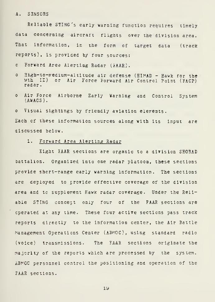
A. SSNSCRS
Reliable STING's early warning function requires timely
data concerning aircraft flights over the division area.
That information, in the form of target data (track
reports), is provided by four sources:
Forward Area Alerting Radar (iAAR).
High-to-iredium-altltude air defense (HIMAD - Hawk for theyih ir) or Air Force Forward Air Control Point (FACP)radar
.
Air Force Airborne Early Warning and Control System(AWACS ).
Visual sightings by friendly aviation eierrents.
Each of these information sources along with its input are
discussed below.
1. Forward Area Alerting Radar
Eight lAAR sections are organic to a division SHORAD
battalion. Organized into one radar platoon, these sections
provide short-range early warning information. The sections
are deployed to provide effective coverage of the division
area and tc supplement Eawk radar coverage. Under the Reli-
able STING concept only four of the FAAR sections are
operated at any time. These four active sections pass track
reports directly to the information center, the Air Battle
Management Operations Center (ABMOC), using standard radio
(voice) transmissions. The FAAR sections originate the
majority of the reports which are processed by the system.
ABI^OC personnel control the positioning and operation of the
FAAR sections.
ly


2. HIMAD/Air force Radar
Information concerning long-range tracks is provided
by the Hawk battalion that supports the division (doctri-
naliy divisions receive direct support from a Hawk battalion
assigned to the air defense organization in support of
corps) or ty the nearest Air Force control facility. This
is accorrplished by an Air Defense Coordination Section from
the SHOHAE battalion (ADCS - one officer, cne MCO, and three
enlisted) which is deployed to the Hawk unit or to an Air
Force Forward Area Control Point (JACP), Control and Report-
ing Point (CRP), or Control and Reporting Center (CRC), when
Hawk is not available. Air Force target information is
received by the Hawk battalion over the AN/TSO-73 Missile
Minaer System (a C2 system connecting HIMAE units to the
nearest Air Force CRC).
3. Airborne Early Warning and Control System
Long-range track information can also be provided by
AWACS. Eeployed prior to the positioning of FACP's or to
extend coverage teyond their limits, these aircraft can pro-
vide excellent long-range early warning. The yth IE has
received direct support from AWACS aircraft during field
training exercises.
4. Friendly Aviation
The division's Flight Coordination Center (FCC) is
the fourth source of track information. Aircraft flying
missions in support of the division maintain contact with
20


liie (ICC). An operations cell frorr the FCC deploys with the
ABI^OC. This cell provides critical information concerning
friendly air operations. Aircraft sightings reported by
pilots are also forwarded to the ABMOC.
B. EASII WARNING DATA TRANSMISSION
Air defense early warning data is transrritted , within
the Reliable STING system, in the form of track reports (see
Table I). Each track report contains data obtained through
the visual sighting or electronic detection of an aircraft.
Reports include aircraft identification, location, size
(number of aircraft), track designation, and aircraft type.
TABLE I
Example Track Report
ELEMENTS Of INFORMATION EXAMPLE
IDENTIFICATION HOSTILE
TRACK DESIGNATOR 347
LOCATION JERSEY 5-5
RAID SIZE ONE AIRCRAFT
AIRCRAFT TYPE FAST MOVER
Location is the most difficult element of target infor-
mation to pass within Reliable STING tecause the FAAR
sections, the ADCS , and the ABMOC each operate on different
reference systems. The Air Force, Hawk, and other HIMAD
21


systems specify locailons in lerms of the World Geographic
Reference System (GEOREF). The ABMOC and. its users utilize
the Universal Transverse Mercator System, with a map scale
of 1:50,200. The FAAR sections operate on an absolute sys-
tem, in which targets are located relative to the radar.
Without a common reference system tracic information could
not he passed accurately and quickly between elements. A
common grid reference is provided through the use of a dev-
ice called the SHORAD Grid.
The SEORAD Grid System is essentially a 400 element
matrix (20-by-20) used for reporting target locations. Each
element of the matrix is a 10-by-10 km square with a dis-
tinct name, "JERSEY" for example. The names are arranged in
alphabetical order from left to right and top to bottom.
The edges of each square are subdivided into 10-1 km incre-
ments. This allows the reporting of locations with an
accuracy of 1 km. An aircraft located in the center of JER-
SEY wculd be announced as, "JERSEY £-5" (see Figure 2).
The matrix covers a 200-by-200 km square, an area far
larger than a standard division area of operations. The
ABf^CC orients the grid over the operating area and reports
the coordinates of the center to all elements that are
involved in the Reliable STING operation. Individual units
use only that portion of the g;rid that covers their area of
operations. It is significant to note that the entire divi-
sion may cover less than 35 of these squares.
22


200 km
T10 KM
1
IOWA JELLO KING
IRISH JERSEY KIOWA
lORN JESSICA KIWI
<—10 KM >
Figure 2. SHORAD Grid
FAAR operators overlay tneir display scope with an acetate
sheet containing the grid aesignators for the portion of the
matrii that is covered by their radar (iigure 3). The ATCS
corrbines the SHORAD Grid System with a GECREE overlay to
provide a means of ccnvertir.g from one system to the other.
23


O - Aircraft located at JERSEY 5-5
Ei^ure 3. FAAR Display With SHORAD Grid Overlay
The rrajority of the early warning track reports are
transmitted tc the ABMOC over five VHF/FM radio links
(nets). One of these nets is utilized by the ADCS and the
rerraining four support the radiating EAAR. Each cf the FAAR
channels is used exclusively for the transrrission of track
reports to the ABMOC, operated as one-way charnels. Opera-
tional control of the EA-aR sections is conducted on a
separate ABMOC operations net.
Long-range track reports are transiritted to the APr^OC en
the air defense coordination net (AECN). The ADCS also uses
24

the ADCN to transrrit corrmana and control lirectives,
exchange coordination inf orrration, and receive track reports
frorr the ABMOC . The ABMOC notifies the AECS of tracks that
threaten Hawk elements (targets that may not have been
detected by Hawk radar due tc masking}.
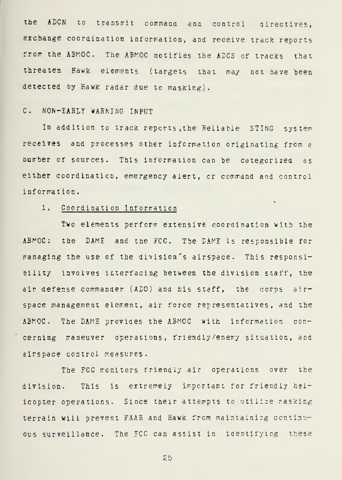
C. NON-EARLY WARNING INPUT
In addition to track reports , the Reliable STING system
receives and processes other information originating from a
number of sources. This information can be categorized as
either coordination, emergency alert, cr command and control
information .
1 . Coordination Information
Two elements perform extensive coordination vith the
ABMOC: the DAME and the FCC. Tbe CAME is responsible for
managing the use of the division's airspace. This responsi-
bility involves interfacing between the division staff, the
air defense commander (ADO) and his staff, the corps air-
space management element, air force representatives, and the
ABMOC. The DAME provides the ABMOC with information con-
cerning maneuver operations, friendly/enemy situation, and
airspace control measures.
The ECC monitors friendly air operations over the
division. This is extremely important for friendly hel-
icopter operations. Since their attempts to utilize nasking
terrain will prevent FAAR and Hawk from maintainirg ccntinu-
ous surveillance. The ECC can assist in identifying these
25


aircraft if they are not identified when they are detected
by friendly units.
2. Errergency Alert Information
Nuclear, Biological, and Chemical (NBC) warnings,
enerry airrrobile alerts, and electronic warfare threats are
examples of emergency alert information. The majority of
these reports originate or are transmitted through toe divi-
sion tactical operations center. The DAME passes these
reports to the ABMOC . Suspected enemy airmohile operations
may be detected and monitored by the ABMOC.
3
.
Command and Control Information
Reliable STING receives air defense command and con-
trol information from two sources: the regional air aefense
commander and the division ADO. The regional air defense
commander prescribes the rules of engagement (hostile cri-
teria and weapons control status), states of alert, and air
defense warnings. These directives are disseminated through
command and control channels an Air Defense Coordination
Section (ADOS - one officer, one NCO, and down to the Hawk
battalion and/or the DAME. They are then transmitted tc the
ABI^CC. Inputs from the division ADO ere received from the
DAME or the SHORAD battalion tactical operations center.
D. ABMOC
The ABMOC is the heart of Reliable STING, performing
four functions which characterize the centralized nature of
the system:


The ABMOC receives track: reports from both short andlong-range sources iientifiea above.
It consolidates these reports to produce a "picture" ofthe division air tattle.
It attempts to correlate the track reports with known airoperations to increase the "value" of the report.
c While these actions are taking place, the ABMOC iscontinuously transritting air defense early warninginformaticn tc the entire division.
The functions identified aoove are all perfcrrred manu-
ally. The ABMOC operation centers around three plexiglass
plotting toards: a main plotting board, a long-range plot-
ting board, and a friendly aviation board (see Figure 4).
Each board contains a diagram of the current division boun-
daries and has the SEORAD Grid etched into its surface
(1:100,000 scale on the long-range board and 1:50,000 on the
friendly aviation and main plotting beards).
Long-range tracks that pose a threat to the division are
initially plotted on the long-range board. The main plot-
ting board is only e0-by-70 km and many of these tracks are
outside its coverage. This procedure also reduces the
number of tracks that must te maintained on the main plot-
ting hoard. As aircraft approach the division, or if the
initial track report from the ADCS is over the division, the
track is transferred to the main plotting beard. The rain
plotting board contains the tracks of all unknown and enemy
aircraft detected over or near the division's area of
responsibility. The friendly aviation board contains ail
the information the ABMOC has concerning friendly air
27


operations (air corridors, ongoing rrissions, preplanned rris-
sioE information, etc.). Tracics are plotted and updated by
five plotters.
FAAR Plotters
LONG-RANGEPLOTTER
LONG-RANGEBOARE
oo ooMAIN PLOTTING BOARL
o o oCIC TELLER AIR OPS
FRIENDLYAVIATION
BOARD
Figure 4. ABMOC Operations
One plotter ironitors the ADCN and maintains the lon^-
range plotting board. The other plotters wotk the main
plotting "board, rronitoring one FAAR each. The plotters rrark
the location identified in the track report on the back of
the board. If the report is an update of a previously
reported track, the point is connected by a line tc the last
reported location. The update reports provide the actual
"track" which can be analyzed ty ABMOC personnel to predict
an aircraft's heading.
28


Positioned where they can observe all three boards are
the Officer-in-Charge (OIC )/Opera tions Officer and the NCC-
in-Charee (NCO IC) /Teller . The OIC and NCOIC correlate the
information on the three hoards. Unknown traclrs are com-
pared to known air operations, in an attempt to determine
possible identification. The OIC is responsible for the
entire Reliable STING operation, to include: determining
FAAR coverage and positioning, controlling "^AAR search
operations and managing the flow of air defense early warn-
ing information to the division. The NCOIC acting as the
Teller, transmits the track reports to the division's users.
I. DIVISION AIR DEFENSE EARLY WARNING NET
Reliable STING transirits information to its users ever
the Division Air Defense Early Warning (DADEW) Net. To
reach its users, the ABr^OC simultaneously transmits both
VHE/E^" and HE/AM signals. The EM signal is intended for
those elements deployed near the ABMOC, while the AM signal
is received t)y three retransmission sections. Each of these
sections maintains an HE/AM receiver which is patched tc a
VHE/EM transmitter. The incoming signal is received on the
HE/AM receiver and retransmitted to users over the UHE/EM
transmitter. The retransmission stations are positioned
where they can support the the majority of the divisional
users (with priority to SECRAD and maneuver units.
The track report (Table I) is also used as the format
for DADEW information. DADEW track reports include the same


types of information as the sensor reports. One additional
elerrent of information is included in track updates:
predicted heading (eight cardinal directions are used,
north, northeast, east, etc.).
30


III. USER INFORMATION REQUIREMENTS
The first step in analyzing the performance of Reliable
STING is to determine the information requirements cf the
system's users. Information requirements will be ordered
from the most basic need to those elements of air defense
information that support optimum user performance. This
entails identification of the users, their missions, the
threat they must counter, and the air defense information
they require to accomplish their missions.
TABLE II
System Users
CATEGORY EECISION MAKER TYPE OF DECISION
1 ADO LONG-RANGE PLANNING
2 DAME, SEORAD CMD MANAGEMENT/COORDINATION
3 FIRE UNITS OPERATIONAL
A. TEE USERS
Any individual that makes use of information provided by
Reliable STING is considered a system user. A list cf
potential users could include the entire division. Theoret-
ically, anyone with a VHF/FM receiver tuned to the proper
frequency may monitor the division air defense early vyarning
net. These information consumers can be placed into one cf
31


three categories based upon the types of decisions they maice
(see Tahie II). [Ref. 5J The decisions that the air defense
elements in each of these categories make, result from their
position within the division air defense organization.
c CATEGORY I - Long-Range Planning Tecisions.
The first category is corrprised of the division airdefense officer (ADO) and his staff. The ADO is taskedwith providing sufficient air defense support to allowthe division comrrander to achieve his goals. He and hisstaff must analyze the enemy/friendly situation, theobjectives of each side, am the status of friendly airdefense assets. All this must he accomplished before theair battle begins.
CATIGORY II - ^lanagement and Coordination Decisions.
The SHORAD leadership (oattery and platccn) and the divi-sion airspace management element (DAME) are concernedwith the implementation of the plans and procedures esta-blished by the ADO, they are included in the secondcategory. The LAME attempts to effectively manage thedivision's airspace hy making decisions concerning thecoordination of air defense and air support assets. TheSEORAD command elements are involved in the management oftheir primary resource, air defense fire power.
CATEGORY III - Operational Decisions.
The third category is made up of the SHORAD fire units.Their major concerns are not planning, management, or
coordination. The fire units make decisions concerningimmediate threats to themselves and the units/assets theyare defending.
This examination will focus on the information needs of
the operational users, the SHORAD fire units. These are the
elements that Reliable STING was designed to support. Their
support is the primary goal of the present system as well.


B. THE SHORAD MISSION
An undersianding of the SHORAD fire units' role in the
defense of the division is a precursor to analysis of their
information needs. This role is identified through examina-
tion of the rrissions perforred by SHORAD fire units in li^ht
of the air threat to the division. Through this examina-
tion, the inherent decisions and the information
requirements can be identified.
1. Air Threat
Before exploring specific elements of the Soviet air
threat, it is useful to examine the general air threat
directed against ground forces. Cohen [Ref. 6] identifies
five elements that compose the air threat:
1. Air threats to maneuver forces deployed for combat.
2. Air attacJcs to the division's central and rearregions against reserves and critical assets.
3. Airborne assaults into the central division area,surveillance and jamming from air vehicles, and otherenemy uses of the airspace over the division which arenot direct attacics.
4. Air threats against targets in the corps and theaterareas by enemy aircraft overflying the division.
5. Air defense suppression by enemy air.
Of these five threats, the first two cause the greatest con-
cern at division level. Soviet aircraft directed ae'ainst
maneuver forces, reserves, and critical assets jeopardize
the accomplishment of the commander's objectives.
Maneuver units deployed along the ?EBA face two air
threats. The first of these consists of high performance
33


aircraft providing close air support for enery ground
forces. The Soviets maintain a large arsenal cf MiG-2l's,
MiG-23's, Su-7B's, and Mig-27's capable of perforrr,ing a
ground attacic role. These aircraft will ingress at lew
altitude to mask their roveirents from HIPAD systems, et
speeds between See and 900 knots. By taking advantage of
terrain and speed, their observation by ground forces can
also be limited. In the vicinity of the target, aircraft
speeds will be reduced to approximately 40e knots, as dic-
tated by the altitude and method of attack.
Attack helicopters represent the second and most
dangerous threat to maneuver operations. The use of attack
helicopters, a tactic developed by the U.S. tc counter the
Soviet ground threat, has become a key element of Soviet
doctrine. Soviet emphasis in this area has produced the
M-24: HIND, the most lethal helicopter in the world.
Heavily armed with anti-tank guided missiles, rockets, and
gun armament, the HIND flys in support of ground forces.
Attack helicopters will operate at much lower speeds than
fixed-wing aircraft, and their ability to take advantage of
masking terrain is greatly increased.
The primary air threat to critical assets in the
central and rear areas of the division and to division
reserves, consists cf high performance ground attack
aircraft. Where low-level flight is important to the accom-
plishment of the opposing force's close air support mission.
34


it is critical to this mission aue the depth of targets
Denind the FEBA.
There are common characteristics in each of the
threats identified above that impact upon SHCRAD fire units'
ability to perform a successful engagement. High perfor-
mance aircraft are going to be flying extremely fast and
very low. These factors combine to shorten the detection
range am reaction time available to perform identification
and engagement decisions. Even though attack helicopters
will fly at much slower speeds than fixed-wing aircraft,
their ability to take greater aavantage of masking terrain
provides the same results.
2. SHORAD f^issions
Divisicnal air defense assets, as shown in figure 5.
include Chaparral, Vulcan, and Redeye fire units. These
elements are deployed to defend maneuver forces, reserve
forces and other critical assets, according to the division
commander's priorities. Chaparral and Vulcan units comprise
the division's air defense battalion. Redeye sections are
currently organic to the artillery and maneuver battalions.
The division ADO (the SHORAE battalion commander)
has historically had more requests for air defense support
than he has had assets capable of supporting. As a result,
the requirements for these assets must be prioritized.
Eased en that prioritization, air defense units are
35


organized for corrbat. This involves task organizing ana
nission assignrrent.
VULCANBATTERY
VULCANPLATOON
4 GUNSPER PLATOON
CHAPARRALBATTERY
1
CHAPARRALPLATOON
1
4 LAUNCHERSPER PLATOON
MANPADSECTION
MANPADTEAM
3-5 TEAMSPER SECTION
Figure 5. Division Air Eefense Assets: Infantry,Mechanized Infantry, and Armcr Divisions
Four tactical rrissions are generally used: Direct
Support (ES), Reinforcing (R), General Suppcrt-Reinf crcing
(GSR), and General Support (GS). It should be noted that
each cf these missions is a support mission, ranging from
decentralized control (direct support) to centralized con-
trol (general support).
The tactical mission specifies the degree of control
the division commander (as advised by the ADO) wishes to
exercise over the SHORAD elements. The tactical mission
identifies who is responsible for positioning the units,
what liaison linKs must De established, and which require-
ments for air defense support will be accepted by the unit.
36


V\jlcan batteries generally provide direct support
for rraneuver units or reinforce Chaparral elerrents to pro-
vide a rrix of weapons and additional fire power. Typical
niissions are defense of critical rraneuver battalions,
rraneuver or logistics conveys, and forward deployed support
assets. Chaparral "batteries are often tasked to provide
general support cf the divisicn or general support-
reinforcing (under GSR another unit would be reinforced when
the battery was net required to support the division as a
whole). Their rrissions would include defense of rear area
assets like the division support corrrrand, brigade trains,
and the divisicn command post.
The Redeye section is deployed according to the
prirrities established by the supported battalion commander.
Redeye teams normally defend maneuver companies, battalion
level assets (command post cr logistic trains), cr some com-
bination of the these.
C. SHOHAD INFCRf^ATICN REQUIHEriENTS
To successfully accomplish the missions identified above
fire units require information from the SHORAD command and
control system. The required elements of information must
first be identified. Once this has been accorplished ,
essential elements of information can be determined and the
users' requirements can be prioritized.
37


1 . Identification of Requirements
Critical to the identification of information
requirements is the realization that the SHORAD fire unit
has ti«o sets of air defense information needs. The first
set is generated by the nature of the fire unit's task: and
includes elements of target information. The second set of
information needs is imposed on the fire unit ty SHCRAD com-
mand end control doctrine. These procedures establish the
user's need for information that provides some degree of
centralized control. Both cf these requirements are ela-
borated helow.
Everything that the fire unit does is related to
engaging aircraft. Therefore, an analysis of the engagement
process will serve as a basis for the identification of the
user's information needs. Lavscn's model of the command and
control process provides a framework for examining the
engagement process (see Figure 6). [Pef. 7] Within the oasic
model there are four functions that must be performed:
SENSE, COMPARE, EECIDE, and ACT. The major functions
included in the engagement process can be identified in this
manner :
SENSE
The fire unit must search the environment fcr aircraft, a
sensing function.
COMPARE
Once an aircraft has been detected, the fire unitattempts to determine its identity through comparison.
36

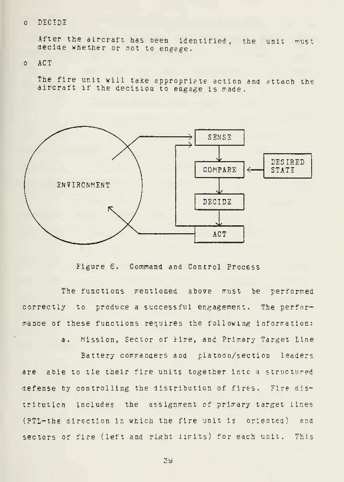
DECIDE
After the aircraft has been identified, the unit rr^stdecide whether or not to engage.
ACT
The fire unit will taKe appropriete action and attach theaircraft if the decision to engage is rrade.
SENSE
COMPARE
DECIDE
ACT
DESIREDSTATE
Figure 6. Command and Control Process
The functions mentioned above must "be performed
correctly to produce a successful engagement. The perfor-
mance of these functions requires the following information:
a. Mission, Sector of iire, and Primary Target Line
Battery commanders and platoon/section leaders
are able to tie their fire units together into a structu^^ed
defense by controlling the distribution of fires. Fire dis-
trituticn includes the assignment of primary target lines
(PTL-the direction in which the fire unit is oriented) and
sectors of fire (left and right limits) for each unit. This
3y

guidance allows the fire unit to focus on a portion of the
environrrent. This procedure can te used to ensure that
there are no gaps in coverage and also reduces the probabil-
ity of unnecessary rrulitpie engagements of the same
aircraft .
b. Air Defense Warning and States of Alert
Advanced warning is required to ensure that fire
unit crews have sufficient time to prepare for action. Air
defense warnings are used by the regional air defense com-
mander to identify the probaoility of air attack. Three
warnings (RED, YELIOW, and WHITE) are used to represent
attack imminent/under way, attack probable, or attack not
probable. These warnings are not geographically specific,
end the entire division will receive the same warning.
States of aiert are closely related to air
defense warnings. They specify the amount of time available
for preparation for engagement (time to assemble off-duty
personnel, prepare ammuniticn, etc. ) . States of alert ere
specified by standard operating procedures (SOP's). Two
examples are: "BATTLE STATIONS", which instructs units to
be prepared to engage aircraft, ana "STANDBY", which directs
units to be ready to execute "EATTLE STATIONS" in a matter
of minutes. The unit SOP would relate these states to the
air defense warnings. Under air defense warning "RED" all
units may be directed to assume "'BATTLE STATIONS".
40


c. Rules of Engagement
Sorre conirol over ihe SHORAD engagerrent process
is exercised through the use of air defense rules of engage-
rrent. Individuals attempting to engage aircraft are aided
and constrained Dy the two components of the rules of
engagement: hostile criteria and weapons control status.
Hostile criteria are used to identify eneny air-
craft. The most common criteria are: aircraft with enemy
markings, the type of aircraft operated ty the enemy, and
aircraft observed attacking friendly units. Additional cri-
teria may be established, for example: "All helicopters
operating over the division between 0600 and 1000 hours are
to be considered hostile." This would be a case where no
friendly helicopters would be operating over the division
during this time.
The second element of the rules of engagement is
weapons control status. Three statuses are utilized:
weapons free, weapons tight, and weapons hold. Weapons free
grants the squad/team leader the authority to engage any
aircraft not positively identified as friendly. '.veapons
tight directs that only those aircraft positively identified
as hostile may be engaged. Under weapons bold units ray
only fire at aircraft which are attacking them or the -nits
they support.
41

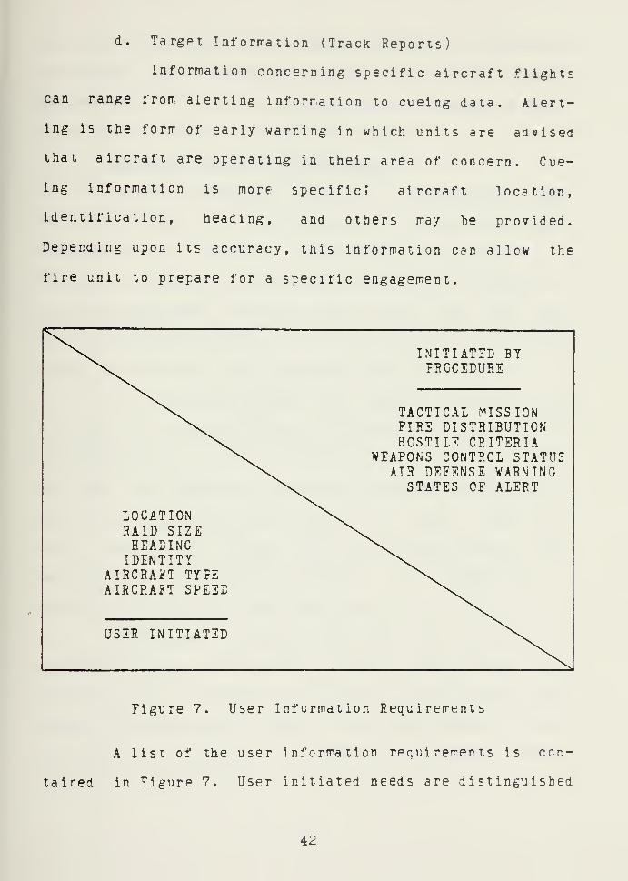
d. Target Informaiion (TracK Reports)
Information concerning specific aircraft flights
can range frorr. alerting inf orrr.ation to cueing data. Alert-
ing is the forrr of early warning in which units are advised
that aircraft are operating in their area of concern. Cue-
ing information is more specific; aircraft location,
identification, heading, and others rray he provided.
Depending upon its accuracy, this information can allow the
fire unit to prepare for a specific engagement.
LOCATIONSAID SIZEHEADINGIDENTITY
AIRCRAi'T TYPEAIRCRAET SPEED
USER INITIATED
INITIATED BYFRCCEDURE
TACTICAL MISSIONFIRE DISTRIBUTIONHOSTILE CRITERIA
WEAPONS CONTROL STATUSAIR DEFENSE WARNING
STATES OF ALERT
Figure 7. User Information Requirements
A list of the user information requirements is con-
tained in Figure 7. User initiated needs are distinguished
4:2

t'rorr those information requirements dictated by operating
procedures. The different elements of specific flight
information have been listed individually, although location
is necessary to give meaning to the others.
2 . Essential Elements of Information
There are essential elements of information that
must be provided in order to achieve minimum effective per-
formance. This level of performance is supported by
providing a mission and the information that is required tc
allow the engagement process to take place. The user must
be able to SENSE, COMPARE, DECIDE, and ACT. If a oy of these
cannot be performed, the engagement cannot taKe place.
To effectively perform the SENSING function, the
fire unit must have a PTL and eir defense warning/status of
alert information. Once the fire unit is assigned a PTL,
the crew can position themselves to search in the desired
direction. The gunner will search +/-45 deg of the PTI,
while other crew members cover 180/360 deg sectors. The
warning/alert information increases the probability of
detection by improving crew readiness.
During the CCMPAKISON function, the decision of
whether or not the aircraft is hostile must be made. The
minimum amount of information required is the hostile cri-
teria. Ttecreticaily , this is the only step that is not
required. It is possible to engage an aircraft without
43


deciding if it is friendly cr hostile. This would be far
short of rrinimum effective performance.
The DECISION function cannot te perforrred correctly
without weapons control status and sector of fire. The con-
trol status, combined v^ith aircraft identification and unit
sector of fire, allows the enga,^ement decision to be made.
Like detection, this function is required if an engagement
is to taKe place.
TAELE III
Minimum Information Bequirements
TACTICiiL MISSIONHOSTILE CRITERIAWEAPONS CONTROL STATUSFIRE DISTRIBUTION
MINIMUM AIR DEFENSE WARNINGREQUIREMENTS STATUS OF ALERT
LOCATIONIDENTIFICATIONHEADINGAIRCRAFT TYPERAID SIZEAIRCRAFT SPEED
The ACTION function requires information concerning
the air defense werni ng/ste tes of alert. The warning/alert
information brings the crew to an increased state of
readiness. Engagement preparations can be made prior to
detection, increasing the amount of time available for
acquiring, tracicing, etc.
44

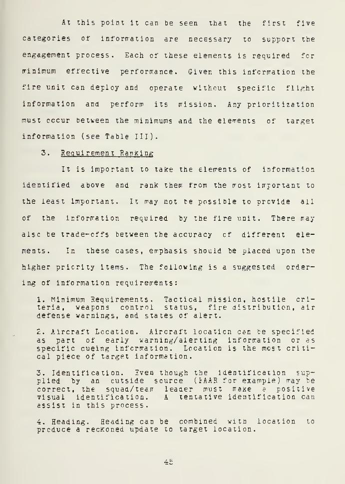
At this point it can be seen that the first five
categories of inforrration are necessary to support the
engagement process. Each cf these elements is required for
rrinimum effective perf orrrance . Given this inforrration the
fire unit can deploy and operate without specific fli^^ht
information and perform its mission. Any prioritization
must occur between the minimums and the elements of target
information (see Table III).
3. Requirement Ranking
It is important to take the elements of information
identified above and rank them from the most important to
the least important. It may not be possible to provide all
of the information required hy the fire unit. There rray
also be trade-offs between the accuracy cf different ele-
ments. In these cases, emphasis should be placed upon the
higher priority items. The following is a suggested order-
ing of information requirements:
1. Minimum Requirements. Tactical mission, hostile cri-teria, weapons control status, fire distribution, airdefense warnings, and states of alert.
2. Aircraft Location. Aircraft location can te specifiedas part of early warning/alerting information or asspecific cueing information. Location is the most criti-cal piece of target information.
3. Identification. iven though the identification sup-plied by an outside source (iAAR for example) may tecorrect, the squad/tearr leaaer must maKe e positivevisual identification. A tentative identification canassist in this process.
4. Heading. Heading can be combined with location to
produce a reckoned update to target location.
45


5. Aircraft Type. The identification of aircraft typeaids in target detection and identification by tellingthe fire unit what to Icck for. The type also providessoire limits on the operating speed of the aircraft.
6. Raid Size. The nurrber of aircraft is another charac-teristic that aids in detection. Fire units are aiscalerted to the possibility of mulitple engagements.
7. Aircraft Speed. Knowledge of the aircraft speed, whencombined with heading end location, can aid in detection.Knowing the aircraft speed is also important when consid-ering how to engage the aircraft.
l*hen aircraft speed, heading, or aircraft type are used as
elements of hostile criteria (example: ".All high-
performance aircraft operating over the division between
e62ee0Z-070800eZ are to be considered hostile.") they would
be as important as identification.
As there is a minimum effective performance, there
must also be an optimum performance. All aircraft that
entered the fire unit's sphere of influence would be
detected. This detection would occur at the maximum range.
All detected aircraft would be identified at the maximum
identification range. Following the engagement decision,
the gunner would destroy each hostile aircraft engaged.
Each of the elements cf target infcrmaticn has an
accuracy associated with it. Identification may be "prob-
able" or "tentative". Location accuracy may establish a
large or small search sector. Optimum performance would be
supported fcy perfect infcrmaticn in each of these
categories. Table IV demonstrates the relationship between
these levels of information support.
46


TABLE IV
Inforrnaiion Requiremenis VersesPerf orrT'ance Level
ELEMENT
MINIMUMEFFECTIVE
PERFORMANCEOPTIMUM
PERFORMANCE
MISSIONHOST. CRIT.WEAP. STATUSFIRE DIST.AD WARNINGST. OF ALERT.
XXXXXX
XXXXXX
LOCATION (SECTORIDENTIFICATIONHEADINGAIRCRAFT TYPERAID SIZEAIRCRAFT SPEED
SIZE) (+/-45)'^ X(+/-l)X(ACTUAL)X(ACTUAL)X(ACTUAL)X(ACTUAI)X(ACTUAL)
X - Informaticn prcvided
=«= - A result of PTL assignnrent(sector size in degrees)
47


IV. INFORMATION RESOURCES
In Chapter III the users' requirements for air defense
information were identified. Any systeip that attempts to
satisfy these requirements must gather substantial amounts
of information. Two basic resources are available to pro-
vide this information: air defense command and control/early
warning information and track reports. Prior to addressing
the effectiveness of any SHCRAD command and control system,
it is necessary to ascertain the adequacy of information
available from these resources.
A. AIR DEFENSE COMMAND AND CONTROL
Air defense command and control information includes all
information di'^ected at increasing unit readiness (reducing
reaction times), establishing support requi rerents , and
maintaining control cf subordinate units. This information
is processed through the air defense chain cf command and
through control and coordination links. Sources of command
" end control information can be found both within and outside
the division, they are:
The regional air defense commander
The division air defense officer
SHCRAD leaders
Maneuver commanders
48


1 . Ixternal lo Division
The regional air defense commander, normally the
senior Air Force commander, is the primary external source
of air defense command and control information. Although he
does not possess command or operational control over the
divisional air defense assets, he does exercise control over
the use of all air defense weapons within the region. He
does this through the use of rules of engagement and air
defense warnings. Rules of engagement and air defense warn-
ings are transmitted to the supporting Hawk battalion by
TSC-73 date link from the air defense group/brigade support-
ing the corps. From the Hawk battalion there are two routes
into the division, resulting from an exchange of liaison
officers between the division and the Hawk "battalion. The
SHOEAD battalion dispatches an eir defense coordination sec-
tion to the Hawk battalion command post and the Hawk
battalion sends a liaison section to the division main
tactical operations center. The SHORAD liaison section col-
lects and transmits information concerning the rules of
engagement and air defense warnings to the SHORAD tactical
operations center (or to the ABMOC in the yth ID), where it
can be disseminated to subordinate units. Prior to the
implementation of MSCS , this information was disseminoted
over SHORAD command nets. Both MSCS and Reliable STING
broadcast these elements of air defense information over
early warning nets. The Hawk battalion also transn'its this
4:y


infcrmation to their liaison section, who reports it to the
DAP^I. Personnel in the DAr^E pass the Inforrration to the
division operations element, who can disseminate it down
through the maneuver chain of command (tactical coirmand post
(CP), brigade CP's, battalion CP's, etc.).
2. Internal to Division
Within the division, air defense comrrand and control
infcrmation is provided by three sources:
The division air defense officer,
c SHORAD battery commanders and platoon leaders.
The division, brigade, and battalion commanders.
The information they provide is identified below.
Tactical missions are assigned at two different lev-
els. The division commander, acting upon the advice cf the
ADO, assigns battery, and in some cases platoon, missions in
the division operations order. Batteries assigned the
mission of direct support come under the control of the sup-
porting unit. Missions for Rede/e teams are determined by
the battalion commander and the Redeye section leader.
Coordination with supported maneuver units at these levels
is an important part of mission definition.
SHORAD battery commanders and platoon leaders pro-
vide information concerning PTL's and sectors of fire.
Depending upon the size and value of the asset, a battery or
platoon-sized unit will generally provide the air defense.
b0


The commander of thai unit will establish these measures for
subordinate units in the construction of his defense.
States of alert are also generated within the divi-
sion. Standard operating procedures identify the states
which correspond to the air defense alert warnings. Battery
corrmanders have the authority to reduce the states of alert
of selected elements in order to rraiotain iocreased long-
term readiness.
Maneuver commanders are given the authority to
implement more restrictive weapons control statuses in their
area of operations. By changing the status, the commander
exercises a greater degree of control over the air defense
fire units within his sphere of influence. This procedure
would "be used in conjunction with critical friendly air
operations.
3. Level of Support
These elements cf information meet the users'
minimum essential requirements (see Table V). The same com-
mand and control procedures that established the
requirements establish the reporting procedures. There Is
no accuracy associated with these categories of information.
The requirement is either satisfied or it is not satisfied.
It should also be noted that because externally generated
command and control information pertains to the entire air
defense region, is well suited for division-wide broadcast.
51


TABLE V
Sources of Air Defense Command andand Conirci Information
INFORMATION PRCVIDIDEXTERNAL INTERNAL
ELEMENT TO DIVISION TO DIVISION
MISSION XHOST. CRIT. XWEAP. STATUS* X XFIRE DIST. XAD WARNING XST. OF ALERT. X
X - Information provided
* - Provided by doth sources
B. TRACK REPORTS
The second major source of information is aircraft tracK
reports. Track report information is required to fulfill
early warning/alerting and cueing requirements. These
reports contain information relating to specific aircraft
flights and may be processed manually cr electronically.
Track reports are originated by Air Force and Hawk radar,
organic FAAR sections, and by friendly aviation.
1. FAAR
The FAAR system is SHORAD's only organic means of
electronic aircraft detection. When used with the target
alert data display set (TADDS), this system is designed to
provided the SHORAr fire units with alerting information for
targets within 20 km of the radar.
5£

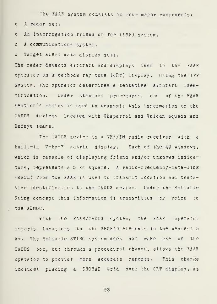
The fAAR system consists of four major components:
A radar set.
An interrogation friena or foe (IFF) system,
c A communications system.
Target alert data display sets.
The radar detects aircraft and displays them to the FAAR
operator on a cathode ray tube (CRT) display. Using the IFF
system, the operator determines a tentative aircraft iden-
tification. Under standard procedures, one of the FAAR
section's radios is used to transmit this information to the
TADTS devices located with Chaparral and Vulcan squads and
Redeye teams.
The TALES device is a VFxi/EM radio receiver with a
built-in ?-by-7 matrix display. Each of the 49 windows,
which is capable of displaying friend end/or unknown indica-
tors, represents a 5 km square. A radio-frequency-data-link
IRFEL) from the FAAR is used to transmit location and tenta-
tive identification to the TADDS device. Under the Reliable
Sting concept this information is transmitted by voice to
the ABr^CC.
With the FAAR/TADES system, the FAAR operator
reports locations to the SHORAD elements to the nearest 5
km. The Reliable STING system does not make use of the
TADPS box, but through a procedural change, allows the FAAR
operator to proviae more accurate reports. This change
Includes placing a SHORAD Grid over the CRT display, as
53


discussed in Chapter III. With this, the operator is able
to estirrate target iocations to the nearest Ikrr. This
information, along with tertative identification, type of
aircraft (fast verses slow), and relative nurber of aircraft
in the raid, is transrritted to the ABMOC, rather than to the
SECHAD fire units.
Experiments conducted during the iy60's and early
iy70's demonstrated that single engine, high-performance
aircraft could he visually detected oeyond 10 e.m. [Ref. 8]
Because these results were achieved under excellent visibil-
ity ccnditicns, detection ranges of 3-6 icm suggested by FM
44-23 [Ref. 9] , are assumed to be more accurate in the Euro-
pean environment. In the remainder of this document, the
raxirrum figure of 8 kr" will be used for comparisons of loca-
tion accuracy. Allowing the fire unit crew to detect at
their maximum detection range should be a major goal of any
early warning system.
Figure 8 illustrates the size of the search sector
corresponding to a 1 km accuracy, at ranges out to 10 km. A
£AAE report with 1 icm accuracy establishes a 7.6 deg search
sector at S km. This represents the report accuracy as the
i'AAR operator prepares to transmit it. If the target is a
high-performance aircraft flying at 40fe; knots, it travels at
ever 200 m/sec. Assuming that the operators report requires
five seconds to transmit (transmitter keying time included),
the aircraft will tidve flown at least 1 km by the end of the
54


SIARCflSIC TOR(DIGRSES
)
50
40
50
20
10
Values were corrpuied withthe otserver iccated incenter of a grid square.The aircraft is located inthe same row as the obser-ver, see i'igure y.
TARGET RANGE (KM)
figure 6. Search Sector Size for 1 Km Report
i'lREUNIT
7^ IKM
A
\
6 = 7.6 Degrees= 22.6 Degrees (5 second report delay,
aircraft speed - 400 knots)A - Aircraft located to the nearest kiloreter
8 fcm from the fire unit.
Figure 9. Sector Size Verses Time Delay
report transmission. The effect of this delay is to effec-
tively triple the size of the necessary search sector (see
tb

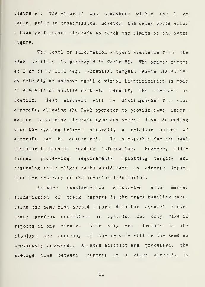
Figi^re y). The aircraft was somewhere within the 1 icm
square prior to transfrission , however, the delay would allow
a high performance aircraft to reach the limits of the outer
figure .
The level of inforrration support available from the
FAAR sections is portrayed in TaMe VI. The search sector
at S krr is +/-11.3 deg. Potential targets rerrain classified
as friendly or unlcncvn until a visual identification is nade
or elements of hostile criteria identify the aircraft as
hostile. Fast aircraft will he distinguished from slow
aircraft, allowing the FAAR operator to provide some infor-
mation concerning aircraft type and speed. Also, depending
upon the spacing between aircraft, a relative number of
aircraft can be determined. It is possible for the FAAR
operator to provide heading information. However, addi-
tional processing requirements (plotting targets and
observing their flight path) would have an adverse impact
upon the accuracy of the location information.
Another consideration associated with manual
transmission of trecic reports is the track handling rate.
Using the same five second report duration assumed above,
under perfect conditions an operator can only make 12
reports in one minute. With only one aircraft on the
display, the accuracy of the reports will be the same as
previously discussed. As rrore aircraft are processed, the
average time between reports on a given aircraft is
56


TABLE VI
Target Information Available toSupport ReliaDle STING
ELEMNT
LOCATION (SECTOR SIZE)IDENTIFICATIONHEALINGAIRCRAET TYPERAID SIZEAIRCRAET SPEED
X - Information provided
X(+/-ll .3)X(FRND./UNK. )
X(EAST/SLOW)X(RELATnE)X(FAST/SLOW)
10
NUMBER 8OF ACBEINGREPORTED 6 .^^ 5 SEC REPORT
INTERVALAC SPEED =
40e KNOTS
1234t678yDISTANCE FLOWN BETWEEN REPORTS (KM)
Figure 10. Distance Flown Between Reports
proportional to the number of aircraft being reported. If
the FAAR operator would attempted to track six aircraft,
57


providing updates on each of their locations, they would
each he reported once every 30 seconds. Figure 10 illus-
trates the proportionality. For en aircraft travelling at a
speed of 400 knots, when the report interval is five
seconds, the average distance (in kilometers) traveled
between reports is approxirrately equal to the number of air-
craft in the system. The update interval is a factor of the
report interval times the number of aircraft being reported.
The update interval times the speed of the aircraft produces
the distance travelled between reports (see the example
heiow)
.
5 sec X e = 30 sec30 sec X k:00 m/sec = 6 km
The FAAR operator is not required to cycle through
all of his tracks, making a report on each one. He n-ay con-
centrate on a particular aircraft that he feels poses the
greatest threat. By doing this, the time, and hence the
distance traveled between reports for that aircraft will
decrease.
2. Direct Surport Hawk and Air jorce
Long-range early warning information is provided by
the Hawk battalion or the Air Force control cecter/point
(CEC ,CRP ,FACP) . The air defense coordination section that
deploys to one of those locations is tasked to provide com-
mand and control information as previously discussed. The
section also provides early warning track reports of air-
craft approaching the division area.
58


At ibe Battery Control Central (BCC) or the Bat-
talion Operations Center (BOC), the liaison officer (LNO)
positions himself where he can observe the CRT display of
acquisition radar returns. He identifies long-range air-
craft tracks that threaten to enter the division airspace.
The GEOEEF location of these aircraft is determined and
transmitted (along with tentative identification and other
elements of information) to the remainder of the section
located nearby. The section plots the tracic in GECREJ" on en
acetate plotting beard. Since this plotting board has
GEOREF coordinates on one side and the SHORAD grid on the
ether side, a location can then be read from the SHORAD grid
side and transmitted, along with the other pertinent infor-
mation received from the LNO, to the ABMOC.
When the observer monitors the radar display in the
BCC or the BOC, he is able to see the targets aetected by
the battery's pulse acquisition radar (FAR) and continuous
wave acquisition radar (CWAR). These radar systems have
operational ranges in excess cf 100 Km and 60 km respec-
tively. To present these radar returns, the CRT display has
a scale at least five times greater than the FAAR display.
The entire SHORAD Grid, whicn represents and area 2Z0-by-200
km, is not large enough to cover the Hawk display. Unfor-
tunately for the sake of accuracy, the displayed radar
returns are approximately the same size as those on a FAAR
display. It is difficult to accurately locate an aircraft
bb


in this manner, when the projection of its radar return is
larger than the unit of measure.
Even if very accurate readings could be made, addi-
tional error is incurred by determining the locations in
GEOREF (to the nearest minute) and then transf orir.ing tbem to
SHORAD Grid coordinates (to the nearest 1 km). The rela-
tionship between minutes and kilometers varies as a factor
of latitude. In Central Europe a minute is approximately 1
krr in longitude and 2 km in latitude. The coordinate
transformation performed by the coordination section cannot
improve this accuracy.
The transformation/reporting process performed by
the section takes at least twice as long to accomplish as
the FAAR operator's reporting. The delays imposed by voice
reporting are basically the same in both locations because
both sources are transmitting identical elements of informa-
tion.
The BOC also receives track information originated
by Air Force sensors. These reports are received via the
TSC-73 link to the parent air defense brigade or group. One
source of information for these reports is the Air Forces'
Airborne Warning and Control System (AWACS), which is linked
to the CRC supporting the corps.
At operational altitude the aircraft has a horizon
of approximately 250 n-iles. This range combined with the
systems ability to identify aircraft from ground, allows
60


AWACS 10 provide exceptional long-range early warning
against low-flying aircraft whicb may be rasked fron FAC? or
Hawif radar. Eeceuse the systerr rrust exclude ground it is
not effective for detecting slow flying helicopters.
The yth ID has operated directly with AWACS during
Joint exercises. An HF/AM voice link was established
between the AWACS and the ABMOC for passing track reports.
However, under standard operating procedures, the AWACS air-
craft transmits high-speed digital information to the CRC.
One of these aircraft is capable of supporting the entire
air defense region. Given the range of its sensors (capable
of covering many divisions) and the importance of its inter-
cepter control mission, it is unlikely that AWACS will
corrmunicate directly with divisional air defense elerrents.
With the exception of heading and location/sector
size information. Table VI also represents the level of
information support available from the long-range sources.
Unlike the FAAR sections, the coordination section is capa-
ble determining an approximate heading without increasing
their processing time. This is because the coordination
section must plot the track reports to transform the coordi-
nates, whereas the itAAR operator dees not. As a result of
the processing delays and CRT display inaccuracies identi-
fied above, the sector size required to locate the target
would be much larger than +/-11.3 deg sector which results
from the FAAR reports.
61


3. DivisioD Aviation
One Of ihe sources of information identified for
Reliable STING is the division's aviation assets. These
aircraft can be divided into two groups: those aircraft
operating along the FEEA, and tnose operating over the cen-
tral and rear regions of the division. The latter grovp
includes utility and cargo helicopters. These aircraft
could observe enemy airrpobile/airborne operations and ground
attacic aircraft directed against assets in these regions.
Along the FEBA , observation and attack helicopters are in
position to ocserve air strikes directed at maneuver ele-
ments, to include enemy attack helicopter operations.
Enemy aircraft sightings are transmitted to the
Flight Control Center (FCC). The FCC transmits these
reports to their cell located with the ABMCC. Because these
reports are visual sightings of moving targets rraae by
observers who are also moving, it is impossible to determine
the accuracy cf any locations received from this source.
4. level of Support
The track report information available to the Reli-
able STING system is capable of satisfying the remainder of
the users' air defense information needs (see Table 711).
The accuracy of the locations provided by FAAR falls between
those required for minimum and optimum levels of perfor-
mance. The information required to support each of these
elements, except for heading, can be provided by FAAR.
62


TABLE VII
Inforrration Avaiiabie to Support STINGReliable STING
ELEMENT
REQUIRED FORMINIMUMEFFECTIVE
PERFCRMANCEINFORMATIONAVAILABLE
RFCUIRED FOROPTIMUM
PERFORMANCE
MISSIONHOST. CRIT.WEAP. STATUSFIRE DIST.AD WARNINGST. OF ALERT.
LOCATIONIDENTIFICATIONHEADINGAIRCRAFT TYPERAID SIZEAIRCRAFT SPEED
XXXXXX
( + /-45)'i'
X
XXXXX
X(+/-11.3)X(iRND./UNK.)X(ADCS)X(FAST/SLCV)X(RELATIVE)X(FAST/SLOW)
XXXXXX
X(+/-l)X(ACTUAL)X(ACTUAL)X(ACTUAL)X(ACTUAL)X(ACTUAL)
X - Information provided
* - A result of PTL assignrent(Sector size in degrees)
Other sources also provide important input. The
long-range track reports bridge the gap between very general
air defense warnings and alerting/cueing information. This
early warning benefits the users in two ways. It increases
their level of readiness and provides the ABMOC OIC the
information necessary to allow him to employ the best combi-
nation of operating FAAR sections. The sightings provided
by division aviation can confirm aircraft identifications
63


and deteci aircraft that may have penetrated the FAAR cover'
age undetected.
64


V. INFORMATION AVAILABLE TO USERS
Having looked at ihe inrorrra iion required by ihe SHCRAD
fire units and the potential value of the air defense infcr-
mation available to Reliable STING, the effect iteness of
providing this informaticn to the user can te assessed.
That assessrrent is made in this chapter in terms of the
information made available to the users. Under the Reliable
STING concept, the ARMOC corrinunica tes three types of
information to SHCRAD fire units. This information is
transmitted over the Division Air Defense Emergency Warning
(DADEW) net.
A. DIVISION AIR DEFENSE EARLY WARNING
1 . Present Early Warning System
The division's methods of disseminating air defense
information are changing as the Army adopts the Manual
SHORAD Control System. The previous system utilized air
defense command and control channels to transmit eiternally
and internally generated command and control information
^see Figure 11 )
.
While the air defense information identified abote
was processed in a centralized manner, control cf short-
range early warning information was decentralized. TAAR
sections were positioned where they could best support
deployed SEORAD fire units. These sections transmitted REDL


or VHF/IM voice to the fire unit TADES devices. Up to eight
sections could operate sirruitaneousiy , each supporting a
different group of users (see Figure 12).
REDEYE REDEYE
Figure 11. Longe-Range Early Warning andCommand end Control Before I^SCS
FAAR
FM RFDL or voiceto TADDS device
C/V
7FAAR EARLYWARNING ^
REDEYE REDEYE
Figure 12. Flow of Stio rt-Re nge EarlyWarning Information
The procedures instituted ty MSCS will continue to
utilize the same channels for the transmission of internal
66


corrmand and contrci and shcrt-range early warning informa-
tion. This system will, however, alter the flow of
information receivea fron outside sources (see Figure 13).
The air defense coordination section transmits this informa-
tion from the ES Hawk battalion to the SHORAD battalion TCC,
as before. The TOC retransmits this air defense information
on their early warning broadcast net. FAAR sections, bat-
teries, and others monitor this net. The i'AAR sections
rebrcadcast pertinent elements to those units irouitoring the
FAAR early warning nets. The command channels between bat-
teries, platoons/sections, and squads/teams are available as
an alternate means of transmission when early warning nets
are not operational.
C/V C/V
EARLY WARNINGBROADCAST
^^ /FAAR EARLYWARNING
HAWK SHORAD FAaR
REDEYE REDEYE
Figure 13. MSCS Network Structure
£. Reliable STING Network Structure
Tne implementation of hSCS procedures does not alter
me basic netwcri: structure. The system still provides
67


aecentra lizea processing of siicri-range early warning and
ceniraiized processing of tJae ciiier eierr,enis of air defense
infornaiicr. The procedures impiemenied ty ihe Reliable
STING coacepi do chantie inis structure. Under Reliable
STING the processing of all air defense infcrrraiion central-
ized except for corrmand and control information internal to
the SHCRAL tattaiicn. Both long and short-range tracK:
reports and corrimand and control inforrration frorr the
regional air defense commander are transmitted to the ASMOC.
The ABMCC then transrits this information to all users (see
Figure 14)
.
JJ . .L
IVISION AIR
^^ ^ WARNING
HAWK
Command and ControlV and Long-Eange
Early 'AarningEAaR
> Short-Range Early Warning
REDEYE
ligure 14. Reliable STING Networic Structure
REDEYE
B. AIR DEEENSI CO^:^!AND AND CONTROL INFORMATION
One of the airs of hoth Reliable STING and NSCS is to
take tbe regional air defense commander's rules of
66


ent^a^emeni and air defense warning information and transmit
them to the users via the rost direct route. Reliable STING
communicates this infcrmaticn directly to each user monitor-
ing the DAEIW net. This action, corbined with the
Droadcastin^ of long-range tracic reports, was designed to
reduce the time required for dissemination of information.
This is an important point. Although seme of the external
command and control information is not time critical
(reports are otten transmitted in advance of implementation
time}, there are instances when these reports must get to
the user as quiclcly as possible.
TAhile the users do receive this information faster under
Reliable STING procedures, they sometimes question the
source. During the RSFORGER '81 comparison of Reliable
STING and MSCS, some of the participants expressed concern
over the lack of authentication on tbe DADEW net. [Ref. 10]
Because the information which was broadcast on the DAEEW net
was intended fcr use at all levels, transmissions were not
encripted and had not teen authenticated. The ABMOC
transmitted changes in the air defense warning and rules of
engagement. As important as these categories of information
were, it was not possible for the users to determine where
the transmissions had originated.
A feedback problem also exists. These elements of
infcrnaiion are critical to providing an effective air
defense. Unfortunately, it is impossible to ensure that ail
6y


the users moritor changes that are broaacast on the CAEEW
net. Because aii transrissions are one-way, the ABMOC does
not receive any feedbacK. The only way leaders of SHOPAD
units can be assured that their subordinates have received
this information is tc ccmrnunicate with them. As a result,
these transrrissions are placed back on the corrrrand nets or
the superiors are forced to assume that the orders were
received .
EfF'ECTIVE INEORhATIONEL2^'E^T PERi ORMANCE PROVIDED
MISSION X XXHOST. CHIT. X XWEAP. STATUS X XEIRE DIST. X XXAr WARNING X XST. OF ALERT. X XX
TABLE VIII
Command and Control Information Providedty Relidhie STING
REQUIRED FORMINIMUM REQUIRED EOR
CPTir^UMPERFORMANCE
XXXXXX
X - Information provided
XX - Provided by SHORAD chain of command
The air defense information provided oy the ABMOC satis-
fies the users' needs for hostile criteria, basic weapons
control status, and air defense warnings. The other ele-
ments of information, identified as essential to producing
70


rrinirrurr etfeciive perfornance , are received fror the SHOEAD
chain of ccmrrand (see Table VIII}.
C. TRACK 5IP0RTS
The iracic repcris vhich are transrritted by the ABr^OC are
basically the sarre as those received fron the FAAR and ADCS.
Any differences are the result of processing performed
within the Aiif^OC. The new tracK rray have an irrproved iden-
tification. A tentative heading is supplied by the ABf^OC.
Tne third difference is that the infornation received from
the AEf^OG viii be olaer, less accurate.
1 . Accura cy
The users ronitoring the DADZW net are not aware
that it is highly liicely that reports have teen in the ABr^OC
for nore than 20 sec. They are also not aware of the impact
this delay has en the accuracy of aircraft location and
heading information. Assuming that the determined heading
IS accurate to -/-22,5 deg (see Figure 15) and that the
traclcs are plotted without error in the AEI^CC, the effect of
processing and reporting delays en the accuracy of location
information is discussed below.
The ABf^OC announces three different types of track
reports: initial, update, and scrub reports. The last is
transmitted whenever it is determined that a track will no
longer be reported (outbound, lost, etc.). A representative
sample of tracks from the HIFCRC-IR '61 comparison were founa
to Lave reauired an average of 26.0 sec for processing and
71


"N
y
Any heading iDetweenthese limits wculdbe announced as East
Figure 15. Accuracy cf Heading Infcrrrat ion
dissemination. [Ref. 11] This figure is somewhat deceiving
because the processing and dissemination times for scrub
reports were included. The processing and dissemination
times for scrut reports were rruch shorter, hut fire units
are not required tc detect scrubs. The average time for
initial and update reports would increase to at least 31.6
sec. The effect of this 51.6 sec delay is analyzed in
Figure 16 in terms of the relationship between speea and
distance. A typical aircraft ingressing into the division
airspace flying 400 ^nots, travels over 6.7 Km while these
actions are taking place. After this amount of time, even a
helicopter flying at 85 Knots will have flown more than 1.4
Km. While this appears tc he a great deal of degradation in
accuracy, another point rust also be realized. The average
time of 31.6 sec dees not include the transmission time
1-^


required for FAAR reporting. When the assumed FAAR
iransiTiission time of 5 sec is added to the tirre required for
ABMOC processing and dissemination, the average delay
increases to 36.6 sec. Now the 400 Knot aircraft has had
sufficient time tc travel nearly 7.8 km, effectively
increasing the search sector to +/-77,2 deg.
AIRCRAFTSPEED(KNOTS)
AVERAGE 31.6SECOND DELAY
500
400
300
200
100
123456789DISTANCE FLOWN IN 31.6 SECONDS (KM)
Figure 16. Distances Flown During ABMOC Processing
2 . Saturation Level
Tracic handling rate is also a problem on the DADEW
net. The sample track reports, on an average, required at
least 6.4 sec to transmit. Without the scrub reports, which
require approximately 2 sec to transmit, this average
increases to over 8 sec. With an 6 sec report interval,
only 7-8 tracKS can be announced per minute.
73


NUMBER 1^0
Of ACBEINGREPCRTEE le
10
AIRCRAFT SPEED = 400 KNOTS8 SECOND REPORT INTERVAL
1234 56789 10 11
DISTANCE ELOWN BETWEEN REPORTS (KM)
Figure 17. Distance Fiovn Eeiween SuccessiveABMOC TracK Updates
Figure 17 demonstrates the relationship between
speed, distance, ana tae nurrber of tracks being processed.
An assupption is rrade that the Teller cycles between tracks,
regularly updating all of them. The figure illustrates that
high performance aircraft may travel as far as 8 Krr between
updates '*hen as fe'* as five are being reported. REFORGER
'81 test team reported that the effectiveness of AEMOC
operations did not suffer as a resi:lt of saturation. [Ref.
12] The load was not so ^reat that the plotters could not
keep up and the Teller was able to continue transmitting
tracK reports to tne users. Figure 17 points out that the
saturation level (capacity) of the system should be based on
the value cf information transmitted to the user. That is,
74


saturation is a measure lo be made external to the ABMOC, at
the user level
.
In the analysis of the HEfOEGER '61 test it was
aeterrr.ined that the rest significant feature of Reliable
STIiMG was its acility to pinpoint aircraft locations. Also,
the rate of correlation between early warning and actual
sightings was quite high. [Ref. 12] It is questionable
though, that a systerr can in fact "pinpoint" a high perfor-
irance aircraft if that aircraft has travelled ever 7.8 km
from radar detection to fire unit notification? How can
fire units capacle of detecting out to 6 km find aircraft
that are 7.8 km from were they are reported? It is possible
that seme of these aircraft were detected in advance of
early warning and others were detected in spite of early
Vkarning.
3 . Impact on Information Value
The main question is, hew do the problems of delay
and track handling rate, created by system processing,
effect the value of the location information? It is impor-
tant to place these problems into perspective. Assuming
that en aircraft is maintaining a constant heeding and
speed. Figure le illustrates the impact of each of these two
factors. The arcs represent the possible location of the
aircraft as the report reaches the fire unit. Because only
eight directions are used, the aircraft may fly along a
heading that is +/-22.5 deg either side of the reported


heading. The disiances oetween successive arcs demonstraie
the effect of the handling rate. The distance between the
apex ana the arc represents the distance fiown between
detection Dy the FAAR and tracK: report receipt by the fire
unit
.
FAAH DETECTION
FIRE UNIT RECEIPT
DISTANCE(KM)
DISTANCE TRAVELLEDBETWEEN REPORTS
Jiigure 18. Exerrple of Delay ana TracKHandling Rate Irrpact
The distance that an aircraft travels between radar
aetection ana fire unit receipt of the tracK report is the
rrost critical of the problerrs identifiea above. The results
from the REFCRGER '81 test indicate that fire units would
receive target locations with errors as large as their rax-
imum detection range. This is acceptable for long-range
early warning, in that the crews are still alerted. How-
ever, the location of fast moving aircraft cannot be
'pinpointed" in this rranner. If cueing information tells
76

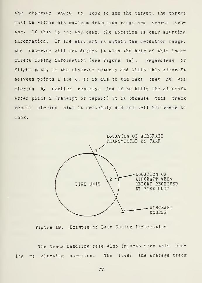
ihe observer where lo iocic lo see the target, the tar,^et
must be within his maximurr detection range and search sec-
tor. If this is not the case, the location is only alerting
information. If the aircraft is within the detection range,
the observer will not detect it with the help of this inac-
curate cueing information (see i'igure 19) . Regardless of
flight path, if the observer detects and icilis this aircraft
between points 1 and 2, it is due to the fact that he was
alerted hy earlier reports. And if he kills the aircraft
after point 2 (receipt of report) it is because this track
report alerted hirr.; it certainly did not tell hirr where to
l00i£.
LOCATION OF AIRCRAFTTRANSMITTED BY FAAR
LOCATION OFAIRCRAFT WHENREPORT RECEIVEDBY FIRE UNIT
AIRCRAFTCOURSE
figure 19. Example of Late Cueing Information
The track handling rate also impacts upon this cue-
ing vs alerting question. The lower the average track
77


handling rate, tiie farther aircraft travel between reports.
As aircrart fly farther between reports, the nurber of tirres
they are reported within fire unit detection limits
decreases. Even if the locations provided by Reliable STING
were accurate, smaller numbers of fire units would be able
to taice advantage of this precise information and its cueing
value would be reducea.
The value of the announced heading also decreases as
the rate declines. Flight path plots are based upon
discrete observations, which can be misleading. The +/-22.5
deg initial reporting accuracy, combined with the inaccura-
cies produced by looking back at these discrete samples,
causes the value of heading information at a fire unit to be
quite low.
Table IX identifies all of the air defense informa-
tion available to the users. All of the elements of target
infcrmaticn required for performance minimum effective
levels are provided by the ABf^OC . V/ith the exception of
location, target information provided by the ABMOC can
improve this level cf performance. Because the assignment
of primary target lines establishes a +/-45 deg search sec-
tor for the gunner, location information disseminated by the
ABf<CC can degrade performance. The sector size necessary to
detect the target is based upon the 400 knot aircraft
eiectrcnically detected 6 km from the fire unit, with a
total reporting delay cf 36.6 sec. Identification is the
78


resuil of ibe JAAR's IFF and A£MOC coordination. Heading is
now availaDie. Aircraft type/speed and the raid size are
transmitted as received by the ABMOC.
TABL2 IX
Information Provided by Reliable STING
REQUIRED FORMINIMUM REQUIRED FOR
iff:ECTnE INFORMATION OPTIMUMSLE^ENT PERFORMANCE PROVIDED PERFORMANCE
MISSION X X XHOST. CRIT. X X XWEAP. STATUS X X XFIRE DIST. X X XAD WARNING X X XST. OF ALERT. X X X
LOCATION (+/-45)* X(+/-77.2) x(V-i)IDENTIFICATION X(IFF+COORD. ) X(ACTUAL)HEADING XILOOK BACK) X(ACTUAL)AIRCRAFT TYPE X(FAST/SLOW) X(ACTUAL)RAID SIZE X(RELATIVE) X (ACTUAL)AIRCRAFT SPEED XiJjAST/SLOW) X(ACTUAL)
X - Information provided
'^ - A result of PTL assignment(Sector size in degrees)
7y


VI. SYSTEM PERJiORMANCE; U1ILIZATI0NCE INEQRr^ATION POTENTIAL
The effectiveness of any information system can be
determined by analyzing how well it utilizes the potential
value or available information. To ascertain the level of
support Reliable STING provides tc the SHCRAi: fire units,
the air defense information provided to these users must be
compared tc the infcrmaticn received by the system. Signi-
ficant differences can then be identified. The processing
performed within the system must then te examined to deter-
mine the cause of improvements or degradations. Once this
has been accomplished, alternatives can be proposed which
ta^e advantage of the system's strong points while address-
ing its deficiencies.
A. INPUT/OUTPUT COMPARISON
Comparing the information that is available to the
system, tc that provided by the system, is basically a com-
parison of the inputs and outputs. In some cases, ABMOC
processing increases the value of the information. In other
instances, the information remains unchanged or its value is
even degraded. The elements of information that enter the
system have a given resource value. This value will be
identified as r. The information that is provided to the
users also has a value: R. The ratio of R/r is a function
et5


of the processing procedure ana liie tirre required to corr-
piete that processing. If the ratio equals 1.0, the infor-
rratiOR value was unchanged by the processing. Greater than
1.0 represents an increase in value, while less than 1.0
identifies a aegraaation.
1. Unaffected Categories
Any category of information that is neither irrproved
upon nor degraded by AliMOC processing consists of inforria-
tion whose value is not tiire sensitive or is not enhanced by
coordination. The regional air defense corrrrander 's rules of
engagement and air defense warning are exarrples of such
infcrrration (see Figure 2^). Because rules of engagement
and air defense warnings are often transmitted in advance of
irrplementation time and the amount of delay delay imposed by
the ABMOC is Tiinimai. This information is complete, there-
fore it should not be expected to be altered by processing.
Raid size, aircraft speed, and aircraft type are
also unaffected Dy systerr processing (see Figure 20). The
number of aircraft reported on the DASEW net is the same as
that received from the sources: ONE, FEW, or MANY. No
attempt is made to determine a precise count. Aircraft
speea and type are really conveyed as one piece of informa-
tion, which is aircraft type. As with raid size, this
information travels the length of the system unchanged.
81


R/r 1.0
RULES OF ENGAGEI^ENTAMD AIR DEiENSE WARNING
PROCESSING TIME
R/r 1.0
RAID SIZE, TYPE, SPEED
PROCESSING Tir^E
R/r 1.0
IDENTIFICATION
PROCESSING TIME
Figure 20. Int'orrr;aiion Value VersesProcessing: Unaffected or Improved
62


2;. Enhancel Information
The value of ideniificaiicn information improves as
a result cf ABMOC processing (see Hgure 20). Remote sen-
sors transmit identification as: UNKNOWN, FRIENDLY, or
HOSTILE. For example, any aircraft that dees net correctly
respond to the FAAH operator's interrogation is identified
as rnicncwn (a visual sighting or special hostile criterion
would be required for him to identify an aircraft as hos-
tile). An incorrect response to the IFF challenge does not
ensure that the aircraft is hostile. A large percentage of
tracks reported to the ABr'^CC will be identified as UNKNOWN.
One major benefit of the system's processing is the reduc-
tion of uncertainty about the unknown tracks. The fire
units benefit from this improvement in information value.
Through the receipt of improved identification, the fire
unit can concentrate its efforts on aircraft that are
suspected to be hostile.
3. Reliable STING Degradation
System processing can also degrade the value of some
elements cf information (see Figure 21). One category in
which tbis occurs is aircraft location. This information,
tae most critical element of target information, is
extremely time sensitive. As demonstrated in Chapter V,
comparatively small time delays can drastically decrease the
accuracy of location information. The example of the 400
83


1.0
R/r
lOCATICN
ALERTING
PROCESSING TII^E
R/r 1.0
HEADING
PROCESSING TIME
Figure 21. Informaiion Value versesProcessing: Degradation
Knot aircraft illustrates tbat the necessary search sector
required for detection grew frorr +/-11.3 deg to +/-77.2 deg,
as a result of processing and reporting delays. This is a
significant degradation. A 22 deg search sector is accurate
cueing information. A 150 deg sector is not much better
than determining that the eneny is expected to attack from
his side of the EEBA.
£4


System processing also has a negative irrpact upon
heading information (see Figure 21). Although heading is
not as sensitive as location information, long reporting
aeiays can degrade these course approximations. This proh-
iem is ccmpounaed vhen aircraft are making frequent course
corrections to take advantage of masking terrain and to con-
fuse air defense elements.
£. HILIA£LZ STING PROCESSING
The examination cf system processing will concentrate on
those categories of information which are impacted by pro-
cessing; primarily identification, location, and heading.
Any propose! alternatives should take advantage of the
system's atility to improve the value of identification,
while attempting to reduce the degradation of location and
heading information.
1 . System Processing
The ABI^CC is not the only node in the system that
performs processing functions. The air defense coordination
section, the FAAR sections, and the fire units also process
track reports. The time required for the processing actions
performed by these elements is not significant when compared
to the time requirei for ABMCC processing.
The coordinate transformation/interface provided by
the coordination section does not significantly affect the
value cf target location information. The long-range, less
accurate nature of this alerting information causes the
8t


impact 10 be relatively minor. This is not the case with
the FAAR sections. Because the FAAR sections are providing
short-range early warnirg, the impact of their processing
can De greater than that of the coordination section, even
though it requires less tirre to corrpiete. The operator is
rot only req'oired to transmit treclr lata; he must also
interrogate aircraft, assign traclc numbers, and follovv these
aircraft, repcrting ty tracic number. These procedures
require a great deal of Hire, affecting the accuracy of the
location information he provides to the ABMOC. The track
handing rate is also degraded as a result of performing
these functions. As the FAAR operator's handling rate
decreases and aircraft fly farther between reports, the
heading determined by the ABMOC becomes less accurate.
Members of the fire unit crew are also required to
process tracic information. Since all track reports are
announced over a single division air defense early warning
net, Indiviauals ronitoring this channel must determine
which reports apply tc their unit. This is a filtering pro-
cess that can be performea by plotting the track reports to
determine if they fall within the unit's area of concern or
by remembering which grid squares border this area and
listening for reports in those squares. Additional time is
required to complete this process, but it is offset by not
encouraging observers to try and detect every aircraft
66

reported, even these well Deycnd the iirrits of their
eyesight
.
2. AEMCC Processin,^
In order to eii^iinete the delays caused by ABMOC
Frocessing, it is necessary to understand how that process-
ing is performed. Eight individuals per shift (sixteen in
total) are required to perform tbis function (see Figure 4).
^ore than half of this crew is employed in plotting the
track reports. They rronitor corr.municaticns frorr the four
FAAH sections and from AWACS cr the coordination section.
Each plotter receives track reports from his sensor and
plots the infcrmation backwards en the long-range or main
plotting boards. lech initial report includes the track
designator supplied by the source. Subsequent updates also
contain this number, allowing the plotter to connect the
points to approximate the flight path.
The of f icer-in-charge (OIC) and the Teller monitor
the air battle from their positions on the opposite side of
the plotting toards. The OIC analyzes the long-range early
warning to assist him in the management of his ?AAR cover-
age. Beth he and the Teller attempt to correlate actions
identified on the long-range and main plotting boards with
the aviation utilization and control information
represented on the friendly aviation board. The Teller also
announces these tracK: reports over the DADEW net. The
actions described above produce approximately 23 sec of the
67


31.6 sec average processing ana aissemination time. If the
accuracy of the output is to increase, this delay rr.ust be
significantly reduced. Efforts directed at reducing this
processing delay must be balanced against the increased
value of identification information which results from this
processing.
Information concerning friendly air activity, which
is portrayed on the friendly aviation board, is received
during coordination with the DAf^I. The route structure to
De used by friendly aircraft, preplanned air operations, II'F
zones, and other coordination information is used by the OIC
and tte Teller to improve upon the identification of unknown
tracks. Aircraft adhering to a predetermined route struc-
ture may be tentatively identified es'friendly, while these
ignoring iriendly coordination measures are suspected hos-
tile. Immediate coordination can also be effected with the
ICC for additional information concerning ongoing missions.
As an initial track is received from one cf the FAAR
sections, it is plotted and the Teller is alerted to this
new track. If the tentative identification is UNKNOWN, the
Teller will announce the track, but he will also observe it
and try to compare its flight path to the flight information
displayed on the friendly aviation board. This requires
observing a few subsequent plots to aeiermine an approximate
heading.
68


3 . Surr.mdry
The processing described above produces both posi-
tive and negative results. Any improverrent in target
identification can help prepare fire units for engagements
and help protect friendly aircraft from ettaciJ by SHCRAD
assets. On the other hand, this processing and the general
plotting/telling actions delay the reporting of tracks to
the fire units.
It has been shown that the degradation of location
and heading information is a result of slow input/output and
plotting procedures. At the same time, it must be noted
that coordination performed by the AEMOC is essential to
improving identification. Some method of displaying tracks
is also necessary to support this coordination process.
C. PROPCSED AITIRNATIVES
Before considering alternatives, the question must be
ask, '"is it required that Reliable STING utilize tne full
potential of available information?" If it can be ack-
nowledged tnat locations transmitted by the ABI^CC are not
accurate enough to cue fire units, a 10 km grid designation
rather than a 1 km report migbt be utilized. Thus the sys-
tem would provide only alerting information to the SHORAD
fire units. With the ABMOC OIC controlling the FAAR employ-
ment and integrating short and long-range early warning
infcrmation, Reliable STING is capable of providing excel-
lent alerting coverage of the division.
ey


The iogicai answer to the above question is "yes". The
system shcuid rriaximize the value cf available informaticn.
In addition to consolidating inforration, coordination with
airspace rranagement elements, and providing early warning to
the entire division, the system should lake advantage of
FAAE/SEOHAD Grid accuracy. Improvement can be realized
through the modification of existing procedures, alteration
of the netvvork structure, automation, or a combination of
these.
1 . Modification of Procedures
In the area of procedural changes, there is very
little that can be dene to streamline the system. The
current proceaures practiced by the ABMOC crew are the
result of en evolutionary development process. The
designers of this system have varied their procedures to
minimize processing delay, while continuing to report each
of the elements of target information. However, realizing
that the main goal is tc get accurate tracK information tc
the fire unit as quickly as possible, some improvement can
be achievsa by changing the reporting procedures.
Using the list cr prioritized information require-
ments identified in Chapter III (see Table IV), track report
lengths could be shcrtenea by removing items of low prior-
ity. Location and identification are the most important
elements of target information, and they should be included
in every report. Announcine only location and aircraft
90


identirication (including track designator) would essen-
tially cut the transmission tirres in half. Unfortunately,
this action would save only 5-8 sec, a small portion of the
total delay.
Therefore, procedural changes offer little potential
for improvement in speed if the advantages of coordination
are tr be retained. Even with a drastic cut in message
length, the JiBMCC processing time does not significantly
change. The processing functicns identified above must
still be performed. Therefore, an order of magnitude reduc-
tion in total delay time could not be achieved.
2. NetworK Structure
In contrast to jroceaural changes, substantial cuts
in delay time can be achieved through structural changes in
the underlying information network. The most obvious is to
stop sending information to the ABMOC before it can be
transmitted to nearby users! Track reports with accurate
location and questionable identification are received by the
ABVCC and track reports with improved identification and
inaccurate location are transmtted over the DADEW net to
the users.
A significant point that seems to he overlooked hy
supporters of Heliable STING is that fire units cannot take
advantage of cueing information provided by the system
unless they are positioned within cr near the coverage of a
lAAfi section (see Figure Z2) . Only Fire Unit A can receive
91


iocdiion cueing information. As determined in Chapter IV,
the JAAH sections are the only sources of accurate cueing
information. To Fire Unit P, not inier the FAAB umbrella,
this same tracic report is only alerting information. Air-
craft must be accurately located 'within the fire unit's
detection range to take full advantage of this information.
FIRI UNITB
MAXIMUM FAAROPERATINGRANGE
EADEW NETIRACK REPORT
ABMOC
iiigure 22. Fire Unit Reliance on FAAR
One of the goals of the system's designers was to do
away with the fire unit's reliance upon a single FAAR
section. They feel that they have succeeded. Alerting
information from a wide range of sources is made available
to the fire unit. However, the fire unit must still depend
lindirectly/ on the nearest FAAR section for accurate loca-
tion information. If the user is positioned near the FAAR
y2


section, why take accurate position data and send it to the
ABr'CC so that it can be returned, after a processing delay,
as inaccurate information?
By changine the control of information to a combina-
tion of decentralized and centralized, the benefits of ABr^OC
processing and the accuracy of the iAAR coi;ld both be util-
ized (see Figure 23). It is possible for FAAB operators to
communicate toth to surrounding fire units and to the ABrOC.
This procedure may require the use of the section's sec
radio or a different antenna configuration. The advantages
are well worth the trade-off. Tracic reports transmitted to
the ABr<CC could be processed to provide alerting information
to elements located throughout the division and target iden-
tification can be improved. At the same time, the fire
units near the FAAR section would receive reports 5 sec old
insteaa of 36.6 sec.
ACCURATE LOCATIONAND TENTATIVEIE5NTIFICATI0N
FAAR
FIRE UNIT
CONSLIEATET ALERTING ANLI^'FRCVEE IDENTIFICATION
FAAR
ABrOC
OTHER SOURCES
Figure 23. .ecentralized/Centraliz ed Information Control
93


To lake advaniage of tbis approach, ihe lire unit
voiild De required to mcnitcr both the EAEEW net and a iccai
lAiiR net. The test corrbination would te to use the HF/AM
radios, planned for I^SCS , for LAEEV' reports and the VEf/FM
radios or TAELS receivers for the FAiiR net. The rrost accu-
rate location information would be available on the lAAR
net, along with a tentative identification. The EAEEW net
would provide alerting information beyond the coverage of
the local FAAR , corrmand and control information, and emer-
gency alert information.
The MSCS procedures are similar to this approach.
Long-range early warning and command and control information
are transmitted to the FAAE sections. The FAAR operators
include these reports with their short-range early warning.
While this approach only requires the fire unit to monitor
one early warning radio frequency, it places a greater bur-
aen upon the 7AAR operator. Since he is the only source of
accurate Iccation irfcrmaticn, his processing load should
not oe increased.
The MSCS procedures also cannot take advantage of
coordination with the EAME and FCC unless flight coordina-
tion information is passed down to tne FAAR sections. Again
the processing load would limit the effectiveness of the
sections .
94


3. Automation
The thin alternative to stanaan Reliable STIMG
operations would reduce tirre delays ty autorrating sore of
the processing and reporting procedures. Recent develrp-
rrents in size reduction and performance enhancement of
micrcccmputers offer a technology that is presently
available at a relatively lew cost. An example of the
application cf this technology is the Theater Target
Analysis and Planning (TAP) system. [Ref. 14] Using commer-
cially available "desic-tcp" computers and peripheral
devices, the Defense Nuclear Agency developed TAP to assist
nuclear fire planners in the corps TOC . This type of
approach is important because one of the goals of this
thesis was to avoid rewriting the requirements for the
automated SE0RAE-C2 system.
For the purposes of automation, it is again impor-
tant to remember the objectives that should be prcmcted.
Irom the users' point of view, the primary goal is to
present accurate and timely information to the fire unit.
The ABf^CC's ability to provide improved identification
through coordination with the DAME/FCC and produce
consolidated alerting inforrraticn are also important charac-
teristics that must te retained.
Automation of Reliable STING should not be a pure
approach, but combined with procedural and structural
changes. Cnly oy reducing the amount of processing and
95


iTinirrizing human participaiion can the lirre delays be signi-
ricaniiy reduced. Some human participation viii always be
required: the user's. With hirri in mind, one must determine:
The method of filtering out pertinent information.
The method of communicating this air defense information.
The examination of Reliable STING processing
revealed that use of a single broadcast net requires the
users to process track reports to see if they are pertinent.
By applying the suggested structural change, this filtering
process can be reducea. If the fire unit receives track
reports from a nearby JjAAR section (one whose umbrella
extendes over the unit's operating area) there is a greater
probability that tnese reports are important to the unit.
A second point taat must be established is the means
t)'/ which the fire unit will receive air defense information.
Units can receive information communicated by voice, graph-
ics device, or text display. Under MSCS a graphics display
(TAIDS) is used and Reliable STING communicates by voice
ever the ZAZE'* net. The Army presently owns ever 2500 TA2ES
devices which only provide location to the nearest t km. At
the same time, the standard FAAR is capable of transmitting
locations (RFDL) to the nearest 1 km. A quick comparison
points out that lAAR/RiDL is as accurate as Reliable STING
and that perhaps something should be done to improve the
TAEDS device.
96


There ere fectors that support improverrert of the
TAIDS systeir. As nientioned above, the/ are already in the
Arrry inventory. The system also has a built-in VHF/FM
receiver. Any new device would require this capability or
would have to ce operated with a tactical 5M radio. With
this in rrina, the possibility of adding sorre lirited logic
capability to the TADDS system snould t?e explored. A
iricroprocesscr capable of perforring the following functions
would greatly enhance the device's capabilities:
Allow the user to change the reference scale frorr t km to1 K:m
.
Transform tne display from sensor centered to weaponscentered or weapons offset. This would include permit-ting the user to enter his location and that of the FAAR.
Provide limitei memory to store the last few FAARtransmissions .
These functions could be accomplished with less processing
power than that available in an advanced hand calculator.
By aiicwing the user to choose the presentation
scale, the device could be used to provide alerting informa-
tion out to 15 icm . As targets would approach the fire unit,
the scale could be changed to take advantage of the sensors
dccLracy. At this point the device would represent a 7-by-7
km square instead of the standard 35-by-35 km. To make this
change effective, an offset user position may be necessary.
iy positioning an observer along an edge of the display, at
least 5-7 Km of display would oe projected towards attacking
aircraft (see Figure i^4). The other alternative is to
97


position the user in the center of the device. While
empicying a 1 itm scale, this wciild project at least 3 km in
ail directions.
A memory capable of storing the last i'ew FAAR
transmissions would also oe required. This would allow the
user to change scales without losing the latest track data.
IKM
IKM
OBSERVER LOCATION
ij'igure 24. Reconfigured TALES Device
When the iAAR operator transmits a SYMBOL ALL CLEAR message,
this memory could also be cleared. Memory size would depend
upon the number of tracks transmitted tetween clearing
operations .
98


In addition to iirproving the display device, some-
thing should be done to automate the rranual procedures
performed by the iAAH operator. The FAAR systems in the
field today require a great deal of manual participation in
the transmission of traclc reports. The FAAR operator has
the option of selecting manual or automatic IFF challenge
procedures. Beycr.d that point the system does very little
ty itself. If the operator wishes to transmit the location
and tentative identity of a given track, he must position a
set of cross-heirs over the target projection using a joy-
stick. Once this has teen accomplished, the operator must
press a button identifying the target as FRIENDIY or UNK-
NOWN. This action causes an RFDL signal to be transmitted
to the TAPES device.
The performance of this system could be improved by
the automation of three functions:
Transmission of target location.
Transmission of tentative identification.
Assignment of track numbers.
Once a target has been challenged by IFF, the results of the
interrogation are represented on the FAAR CRT display. This
information is transmitted ty the Receiving System to the
Display System. [Hef. 15] A microcomputer could combine this
information with the target locations stored in the Data
Link System to free the operator from having to manually
select the identification. Since target locations are
yy


stored, a computer corla access this data and cycle through
the current targets autorat icaiiy transrri tting the latest
iocaticn infcrmati en . The SYMBOL ALL CLEAE signal could be
periodically transrri tted , as well.
In addition tc location and identification, the FAAR
also transrrits a radar identification pattern and a separate
alert signal tc identify a new tracic (one that has not teen
transrritted oefore) . Vith these two pieces of information,
tracK nurrters coula te generated. A block of tracK numbers
could be available in the software (1-100, for example).
When a new target is detected the computer selects the next
unused number and combines it with the FAAR identification
tc produce the aircraft tracic numter. Inclusion of this
number in FAAR transmissions would aid the ABMOC operators
in their tasic cf information correlation.
The goals of utilizing the ABMOC's ability to
improve identification information and provide consolidated
alerting information cannot be realized unless this target
information is also transmitted to the ABMOC . If the first
step in automating Reliable STING is from the FAAR to the
fire units, the second should be from the FAAR to the ABMOC.
Zach of the FAAR sections broadcasts on a different
VHF frequency. This prevents interference iDetween sections
and allows fire units to change sensors by changing the fre-
quency setting on the TAEDS device. The fact that they
operate on different frequencies also eliminates the need
100


for the AEMOC to synchronize or otherwise control their
transmissions. These transtrissions couia te treated as
asynchronous and collected by a microcomputer acting as a
concentrator.
The concentrator vouid have separate ports and
DUfl'er space for each cf the sensors (see iigure 25). Each
buffer vould hold the last track report received from the
iAAR section. The concentrator would access the buffers in
a cyclic manner, transmitting the FAAR reports at a much
higher speed to another computer, which could drive a CRT
display or relay reports to the DAME, ECC, and others.
These procedures could be implemented in the ABf^OC without
automating the EAAR. The REDL signals initiated by the EAAR
operator could also provide the inputs for this system.
FAAR INPUTS
^
CONCENTRATOR
Bl
Bn
OUTPUTS
^
TRACKREPORTBUFFERS
Figure 25. FAAR Concentrator
101


In order to perforrr its coonination and dissemina-
tion functions, the AEMOC requires the capability to:
Lisplay traci: data.
Perl'orrr heading calculations, coordinate transt'orrrations ,
and other computations.
Eisplay coordination measures.
Display t'rienaly air defense assets and radar coverage.
c Communicate cccrdination information to the DAM2, FCC,and Arcs.
c Disseminate early warning, command and control, and emer-gency alert information.
FAARINPUTS
CONCENTRATOR
AIRijATTLEMONITOR
TRACKREPORT
INTERNALEAaR
NETWORK
SUPPORT EQUIPr^ENTAND/OR OTHER MICROS
COMMSPROCESSOR
Figure 26. Automated STING Network
These functions could te performed by a group of microcom-
puters and their supporting equipment, connected by a
high-speed local netwcrlc {see figure 26). As stated above,
tracic reports could be communicated to an Airbattle
102


Moniior siaticn. Ai ihis siaiicn, the OIC or NCOIC could
Observe the traclcs (long and short-range), while coordinat-
ing fAA? coverage. At a second station, perhaps the "Track
Report" station, tracic reports would be exarrined end dissem-
inated fc/ the Teller. Unicnovn reports would te corrpared to
airspace coordination r'easures, which could be eccorrpl ished
either manually or automatically. Updates to aircraft iden-
tity would be transmitted to ail the other stations.
There are other functions that could also he
performed by an automated system. If tracK numbers were
available, the system could approximate the heading in the
same manner as it is computed manually. If a clocic device
was used to date the track reports (time of receipt), an
approximate speed could also be determined. Coordinate
transformations could be performed automatically.
The third step in this automation process would be
to networK the A£[^OC, ADCS , DAMI , and FCC (see Figure 26).
Ifthereas the FAAE links would be one-way, two-way communica-
tions are required between the ABr^OC and each of these
stations. The majority of the traffic would, however, be
originated by the AEI^CC . Since these elements are not co-
Iccated, military telephone or radio links would be required
to connect them. A microcomputer finctioning as a communi-
cations processor could be utilized to interface between
these stations and the internal ABMOC network.
10'6


To reduce the amouni cf processing performed fcy the
ADCS, an atterpt should be made to extract inforrration from
the autorratic data links which connect the Hawk BCC to the
batteries and the air defense group CP. The coordination
section's corr.puter could display the tracks passed on these
linKs en a CRT along with the short-range tracks provided t)y
the AiMOC. Long-range tracks that appear to threaten the
division could be selected for transmission tc the division.
The cornputer's software could continue to update these
tracks .
The APMOC's consolidated alerting inforrration, air
defense comrriand and control, and emergency alert inforrration
would be broadcast by voice to the entire division. This
procedure, the same as used today, would be sufficient for
alerting information. This is true, only because the FAIR
\K0uld be transmitting cueing information tc the fire units.
These voice transmissions would also allow any divisional
units to receive the inf orn-ation .
Target information can be transmitted to the fire
unit much faster with SFDL, than by utilizing standara radio
transmissions. However, an accurate display device is
required to take advantage of this speed. The FAAR
transmissions are also the Key tc enhanced effectiveness of
A5I^0C operations. If tracK report processing functions were
autor.ated and voice transmissions by the FAAR sections were
continued, large reductions in delay time would not be
124
•p


possitie. By entering RJDI signals into the syster, the
delays caused ty the i'AAR cperatcr and the AEf^CC plotters
could be elirrinated.
1^5

VII. SUMMARY, CONCLUSICNS, ANC RECOMrZNDATICNS
A. SUMMARY
The SHORAD fire unit was identified as the prirrary user
cf the air defense information provided by the Reliatle
STING Zariy Warning Systerr. When tnis user's inforration
requirements were identified, the elements cf information
essential for minimum effective performance where also
determinea. Excluded from these minimums was short-range
early warning information, the accuracy of which represents
the difference tetween rrinimum and optimum levels of infor-
mation support.
It was found that the sources of information available
to Reliable STING proviaed the system with the necessary
information to satisfy the user's requirements. Short-range
early warning produced by the iAAR sections was determined
to be the most accurate in terms of target location. How-
ever, this accuracy was significantly degraded while the
traci report was being processed. This same processing
improved the value of identification information and did not
affect the essential elements of Information. The differ-
ences in value between the system's inputs and outputs
resulted from the slow manual procedures performed by the
ABMCC operators and the centralized approach to information
processing.
106


The suggested enhencements were directed at providing
greater inforrration value by reducing the delays associated
vith the present concept. The determination was rrade that
processing delays could be reduced Dy nodifying procedures,
altering the underlying structure of the systerr, autorrating
processing functions, or some combination of these three
approaches.
B. CONCLUSIONS
Analysis of the Reliable STING concept produced the fol-
lowing conclusions:
Reliable STING provides a frarreworic for managing the flowof air defense information more effectively than previousSRGRAE command and control procedures. Even though itsmanual processing is slow in terms of short-range earlywarning, the system is capable of providing timelytransmission of long-range early warning, externally gen-erated command and control information, and emergencyalert information.
c It is impossible for the APf^OC to provide accurateshort-range early warning information. High performanceaircraft fly too fast for the system to handle. Thedelayed track reports, transmitted by the system, provideadequate support for long-range planners and intermediatelevel coordinators and managers. However, the opera-tional users (the fire units) require the potentialaccuracy of this short-range early-warning information toincrease their level of performance above the minimum.
The ability of the AEhOC to improve identification infor-mation through cccrdinaticn and consolidation should notbe degraded. This is a valuable function that will stillhave tc be performed when SHORAD weapons are deployedwith ISi devices. The identification determined by a
Stinger IFF will not be any better than that provided byrAAR or HawK: interrogation devices. This improved infor-mation would else allow fire units to concentrate theirefforts on aircraft which are suspected hostile.
107

Bcih Reliable STING and the enhanced MSCS should adoptdecentralized procedures for processing short-range earlywarning inforrr.a ticn. Whether the systems functions areautorrated cr remain rranual, this step would greatlyirr.prove the accuracy of location and heading informationprovided to the fire units.
The performance of Reliaole STING could be greatlyimproved through automation of its information processingfunctions. Beth the track handling rate and the totalnumber of aircraft that could be processed wculdincrease. Ai the same time, the delays imposed uponshort-range early warning information would be signifi-cantly reauced.
C. RECCr^MSNDATIONS
The following recommendations are made:
Reliahle STiNG's procedures for transmission of sbort-range early warning should be altered. FAAR sectionsshould broadcast tracJc report information tc surroundingfire units, in addition to their transmissions to theABhOC
.
To maximize the effectiveness of the FAAR sections, theAliMCC OIC should ensure that these sensors are positionedto provided accurate cueing information for fire unitswith the most critical missions. Positioning FAAR sec-tions to provide alerting coverage of the entire divisionend to supplement the coverage of Hawk sensors snould notte the only considerations.
ifire units should be provided with a device which wouldallow them to receive digital cueing information. Poten-tial improvements to the TADDS device should he examinedtc determine possible hardware and firmware combinationsthat could be applied to this need.
Automation of AE^'CC functions should he explored indetail. Track receipt, processing, and coordinationtasKS should be analyzed to determine the configuration,size, and performance requirements for such a system.Existing systems, the Theater Target Analysis and Plan-ning system for example, should be examined to determineif their features and configurations are applicable.
106


LIST OF REilRSNCES
1. Operations , FM 1065-5, Heaaquarters Department of theArmy, p. 2-19, l July iy76.
2
.
U.S. Arrry Air Defense Artillery Errri oyrrent . ChaT:arrdl/Vulcan , Change 2 to i'h 44-3, Headquarters Department ofthe Arrr,y, p. L-1 , undated.
3. U.S. Training and Doctrine Command (THADOC) Project No.l-FO-268, Force DeTeloi^ment Test end Exrerlmente t ion ofEnhanced r^anual SHORAD Control System (MSCS) in Eurore .
Putrran, G.H., COL U.S. Army, p. 1, November lyei .
4. Long, H.B., MAJ U.S. Army, "Reliable SHIELD, Sth Infan-try Division Airspace r^anagement
.
" Air Defense , d. 24,April-June 1960.
5. Lucas, H.C., Jr., Information Systems ConceiDts forManagement , p. 37, McGraw Hill, 1978.
6. Cohen, D.A. and Jones, R.F., MAJ U.S. Army, TheDevelopment of Division Air Defense Command ar^d ControlArchitectures . R S. D Associates, p. 11-12, June 1981.
7. Lawson, J.S., "Naval Tactical C3 Architecture: 1985-1995," Signal , t. 32, p. 72-73, August 1978.
8. Baldwin, R.D., Capabilities rf Ground Observers to
Locate, Recognize, and Estimate Distance of low-FlyingAircraft , p. 5-13, Human Resources Research Organiza-tion, March 1973.
9
.
U.S. Army Air Defense Artillery Employment, Redeye , EM44-23, Headquarters Departnent of the Army, p. 4-3, 30December 1977.
10. TRADOC, Force Development Test and Exrerimentat ion ofEnhanced Manual SHORAD Control System (MSCS) in Eurcue,p. D-6.
11. Ibid. , p. 10.
12. Ibid., p. 13.
13. Ibid., p. 9,24.
14. Schneider, W.P., "Small Computers in the Army: An AppleA Day to Keep the Soviets Away
,
" Signal . t. 36, p. 40-42, February 1982.
109


15 . Procedures and Drills for For\^ard Area Alerting Radar( ?AAR) , Fm 44-6, Headquarters Department of the Amy,p. 2:10-11, February 1974.
110


INITIAL DISTRIBUTION LIST
No.Copies
1. Lefense Technical Infcrmaticn CenterCameron StationAlexandria, Virginia 2^314
Z. Library, Code 0142Naval Postgraduate SchoolMonterey, California 93940
3. Assoc Professor S.H. Farry, Code 55PaDepartrrent of Operations ResearchNaval Postgraduate Schooll^onterey, California 93940
4. MAJ J.L. Ellis, Code 55EiEepartrrent of Operctions ResearchNaval Fostgradi:ate SchoolMonterey, Califcrcia 93940
5. LtCol J.W. Johnson, Code 39Naval Postgraduate SchoolMonterey, California 93940
€. Professor M.G. Sovereign, Code 55ZoChairman, C3 Academic GroupNaval Postgraduate SchoolMonterey, California 93940
7. Professor J.M. Wczencraft, Cede 74Department of Electrical EngineeringNaval Postgraduate SchoolMonterey, California 93940
8. CommanderU.S. Army Signal Center, Fcrt GordonAttn: EC'D-^ajor Eruce EisentroutFort Gordon, Georgia 30905
9. Deputy Under Secretary of the Army fcrOperations ResearchRoom 2E261, PentagonWashington, DC 20310
ill


10. Deputy ComrranderUSA CACEAAnn: ATZL-CAC-IAFort Leavenworth,
(CPT Reese)Kansas 66027
11. Commanderyth DIVAEAAttn: AFVO-ADE (MAJ Prarr,blett)ioTi Lewis, Washington ye423
112


TBeslsR2763c.l
Reese
Analysis ofi thereliable STING earlywarning system.
A
ThesisR2763c.l
Reese
Analysis of the
reliable STING earlywarning system.
