thermomechanical modeling of glass cooling including
TRANSCRIPT
23ème
Congrès Français de Mécanique Lille, 28 Août au 1er
Septembre 2017
Thermomechanical modeling of glass cooling including thermal
radiation using P1 method
Kossiga Agbokaa*, Fabien Béchet
a, Philippe Moreau
a, Dominique Lochegnies
a
a. UVHC, LAMIH, F-59313 Valenciennes, France
* Corresponding author
Email address: [email protected]
ABSTRACT
Glass tempering consists in heating a glass product over its transition temperature followed by a
rapid cooling to the ambient temperature. This process is used to improve the mechanical resistance
of the glass product with compressive stresses on the surface and tensile stresses in the core. The
mechanical behavior is very dependent on the temperature, therefore an accurate knowledge of the
heat transfer during the cooling process is highly necessary to obtain the best estimation of the
residual stresses. Since glass is a semi-transparent material, thermal radiation takes place in addition
to the conductive heat transfer especially at high temperatures. In this paper, we performed an
axisymmetric modeling of glass tempering for a circular disk in contact with a metal mold including
radiative effects computed by the P1 method and compared the thermal and mechanical results to
experimental measurements. Good agreements with the experimental results are obtained.
Keywords
Glass tempering, thermal radiation, residual stresses
1 Introduction
During industrial processes, glass is necessarily cooled. This more or less fast cooling leads to residual
stresses in the glass products. One may want to have no residual stresses in order to have further
operations on the product (like cutting) or oppositely to have residual stresses. Quenched glass
products are more resistant and are used for security purposes because when fracture occurs, it leads to
small pieces with blunt edges which are harmless for the user. The tempering process contributes to
improve the mechanical behavior which is temperature dependent. Therefore, it is necessary to have
an accurate knowledge of the heat transfer occurring during the cooling process.
As glass is a semi-transparent material which means thermal radiation is simultaneously emitted and
reabsorbed inside the glass for wavelength of the semitransparent domain, radiative effects should be
taken into account during the cooling process especially at high temperatures. This is done by solving
the radiative transfer equation (RTE). The RTE is so complex that different methods [1], [2] are
developed to solve it. Some of these method are discrete ordinate method (DOM)[3]–[5], Monte Carlo
method[6], [7], finite volume method, PN approximation method.
In this paper, we developed thermomechanical models of a glass disk supported by a metal mold using
the P1 method to compute the radiative effects. Experimental measurements were performed to
compare both experimental and numerical results and investigate the influence of thermal radiation on
the heat transfer and the mechanical behavior.
2 Conductive and radiative heat transfer modeling
In this paper, a glass tempering model including thermal radiation was developed. A glass disk in
contact with a metal mold (Figure 1) is naturally cooled from a given initial temperature. The
numerical results were compared to experimental results. The finite element model is axisymmetric.

23ème
Congrès Français de Mécanique Lille, 28 Août au 1er
Septembre 2017
The glass domain modeled (Figure 1) is defined as: and
. The mold domain is given by: , . The glass
and the mold surface are denoted and respectively. Since glass cooling occurs over time
between 0 and , we defined as the domain occupied by the glass over time which is given
by: . The glass surface over time is denoted
and the contact zone
Figure 1 : Axisymmetric description of the model
The heat transfer that occurs during the cooling process of the glass disk is described by the heat
equation in cylindrical coordinates:
(1)
The subscrpit « » is related to the glass. is the heat conductivity of the glass, the specific heat,
is the temperature depending on the position in the glass and the time, and the initial
temperature of the glass disk, is the divergence operator in cylindrical coordinates system
with the azimuthal coordinate. represents the divergence of the radiative heat flux in
the semitransparent wavelength domain which depends on the temperature of the position in the glass.
The boundary conditions are given by:
(2)
(3)
where is outer normal vector of the surface of the glass domain. Equation (2) shows that the
heat flux on the boundaries of the glass is composed of two terms. The first one is the convection with
the surrounding air at temperature and is the convection coefficient. The second term is the
radiative heat flux on the glass surface in the opaque wavelength region [8]–[11] given by:
(4)
With the hemispherical emissivity of the surface; the Planck function depending on
the wavelength and the temperature of the position which is expressed as:
(5)
is the light speed in the vacuum, the Planck’s constant, Boltzmann’s constant and is the glass refractive index. denotes,
the Planck function in the vaccum (air).
For the mold part, the heat transfer equation is:

23ème
Congrès Français de Mécanique Lille, 28 Août au 1er
Septembre 2017
(6)
(7)
(8)
Where subscript « » is related to the mold; is the mold temperature and is the radiative
flux on the mold surface. As the mold is an opaque material, is:
(9)
With , the constant of Stefan-Boltzmann.
In the contact zone, the interface flux for the glass is expressed as:
(10)
For the mold part, we have:
(11)
is the themal coefficient exchange between the glass and the mold; and are radiative
flux vector on the glass and mold respective surfaces in the contact zone. To determine the radiative
fluxes in the equation (1) and (11), the radiative transfer equation must be solved.
3 Radiative transfer equation (RTE)
In the semitransparent wavelength range , emission and absorption of thermal radiation
occur inside the glass and we assume that there is no scattering of the radiative energy. Since the
absorption coefficient depends on the wavelength, the band model is introduced by the following
expression:
(12)
is the number of the band, and are respectively the lower and upper limits of the band . In
this paper, we will use five bands presented by Viskanta et al [12] for soda-lime glass.
For each band , we define
the integral the Plank’s function over the band.
This expression is independent of . In this paper, we use the P1 approximation method to solve the
RTE. The radiative transfer equation for the P1 approximation method in axisymmetric coordinate
system using the band model is given as [1] :
(13)
is the incident radiation coming from all directions to the position in the glass. The boundary
conditions assuming emission and specular reflection are given by Larsen et al [13]:
(14)
(15)
where and are coefficients calculated by Klar et al [14] for the
refractive index of glass . For more details for the calculations of and , see reference
[13]. For the band model, the divergence of the radiative flux in the equation (1) follows:
(16)
In the contact zone, for the glass, only the surface emission in the opaque wavelength domain is
considered.

23ème
Congrès Français de Mécanique Lille, 28 Août au 1er
Septembre 2017
(17)
For the mold, in addition to the surface emission in the opaque wavelength domain, we have
leaving the glass surface and absorbed by the mold and
is emitted by the mold surface in the semitransparent domain. The total flow for
the mold in the contact is then:
(18)
To solve the radiative transfer equation using the P1 approximation, a finite element method program
was written with Matlab® software and the results were computed to calculate the divergence of the
radiative heat flux which was then injected in Abaqus® calculation.
4 Mechanical behavior modeling
The static equilibrium of the glass disk in the absence of gravity and inertial forces in a cylindrical
coordinate system is:
(19)
With the Cauchy stress tensor; for an axisymmetric problem, equation (19) becomes:
(20)
The displacement vector in the glass is written as:
(21)
For the boundary conditions, we have:
Since the problem is axisymmetric, the radial displacement is null on the axis (Figure 1)
(22)
The glass surface
is free of external forces
(23)
On the contact interface , we have a unilateral contact condition where the displacement
must satisfy the Signorini condition. It states that bodies cannot interpenetrates and only
contact forces exist when the distance between the bodies vanishes [15].
The stress tensor and the strain tensor are linked by the constitutive law.
At a given temperature, glass has a viscoelastic behavior [16]. The assumptions and the viscoelastic
properties used for this model can be found in references [17], [18]
5 Experimental procedure for the glass tempering

23ème
Congrès Français de Mécanique Lille, 28 Août au 1er
Septembre 2017
Figure 2 : Steps during the glass tempering process
In order to validate the numerical model described in the previous sections, cooling experiments were
performed on glass disk. The radius of the glass disk is and the thickness . We
used a structural steel of grade S235 for the mold. The external radius of the mold is and
the thickness is . To investigate the influence of the contact area on the thermal and
mechanical behavior, we used different inner radi ( ) (Figure 1) for the mold.
In this paper, we present just the results for (disk) and (ring).
In the first step of the tempering process, both of the glass disk and mold were heated in a furnace at
625 °C. The heating time was 2 hours in order to have a homogeneous temperature inside the glass
and the mold. A thermocouple of type K was introduced in the mold at 2 mm from the upper surface
to monitor the temperature during the heating step and to assume that we reached the wanted
temperature.
In the second step, the glass and the mold were taken out of the furnace for the cooling process.
During the cooling step, the temperature change on the top surface of the glass was recorded using an
infrared camera while the mold temperature was saved with an acquisition system from Gantner
Instrument. We used Optris PI450 infrared camera which has a wide temperature range from 200 to
1500 °C. Figure 2 shows the different steps of the tempering experiment.
Once, the glass and the mold temperatures reached the room temperature, the glass sample was
observed with a circular polariscope to visualize the distribution of the phase retardation induced by
the residual stresses state in the glass.
6 Input data for the model
The dimensions of the glass disk and the mold modeled were the same as in section 5 in order to
compare the numerical results to the experimental data. The experiment was conducted in natural
convection, so the convection coefficient was taken the reference [12] and was .
The contact conductance was [19]. The surrounding temperature was and the initial temperature was for both glass and mold domains. The thermal conductivity of the glass [20] and the mold [21] were given by the following expression
respectively:
(24)
(25)
The specific heat of the mold [21] is expressed as follows:
(26)

23ème
Congrès Français de Mécanique Lille, 28 Août au 1er
Septembre 2017
Where is in . The glass one was taken from [20]. The densities of the glass and the mold were
respectively and . Glass and mold emissivity were taken from [9].
Figure 3 : Meshing of the model
The thermomechanical model was solved using Abaqus® software. The glass and the mold domains
were meshed such a way to avoid mesh dependent results. The mesh was also refined near the surfaces
and the contact zones (Figure 3) in order to have an accurate estimation of the temperature gradient
due to the convective and radiative effects and also an accurate computation of the incident radiation
which has high gradient at the surface vicinity. CAX8T elements with biquadratic interpolation
for displacement and bilinear interpolation for temperature were used to solve mechanical and
thermal equations. For each time increment, the RTE was solved using the same mesh in the
glass and the divergence of the radiative flux computed was injected in the Abaqus®
calculation via a subroutine written in FORTRAN.
7 Results and discussion
7.1 Temperature results
In this section, results for temperature were compared to the experimental data from the cooling
process exposed in the section 5. The thermomechanical model presented before was performed and
coupled with the P1 method to compute the radiative effects. To investigate the influence of the
thermal radiation on the heat transfer, a model taking into account only conductive heat transfer and
another one with surface radiation on the boundaries of the mold and the glass were performed. The
model without thermal radiation was noted “Norad” and the second one was called “Rad”.
The comparison of the numerical results to the experimental data for the glass supported by the mold
with was shown in the Figure 4 on one hand and on the other hand, the one for the glass
supported by the mold with in the Figure 5. For both figures, the temperature change
was plotted for the point .
23ème
Congrès Français de Mécanique Lille, 28 Août au 1er
Septembre 2017
Figure 4 : Temperature in the center of the upper surface of
the glass tempered with the mold of
Figure 5 : Temperature in the center of the upper surface of
the glass tempered with the mold of
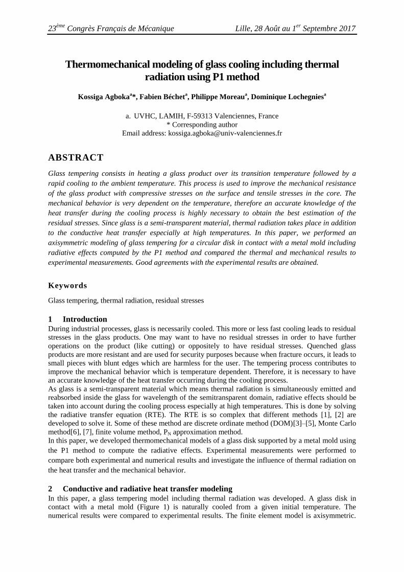
Figure 4 and Figure 5 show a great difference between the model the experimental results and the
numerical one for the model without thermal radiation effects while a good aggreement can be
observed with the model with the surface radiationand the one coupling the radiative effects computed
by the P1 method. Computing the radiative effects inside the glass brings a better accuracy in the
numerical results. The cooling rate of the glass was affected by the contact area . The
temperature of the glass supported by the mold reached after . The glass
disk in contact with the mold ring of had its temperature under after . This
results from the fact a small surface of the glass is in contact with the hot mold leading to a higher
surface cooled by natural convection. The cooling rate gets high when the contact zone is small.
Figure 6 : Temperature difference between the simulaion and
the experimental data for different convection coefficient
(disk)
Figure 7 : Temperature difference between the simulaion and
the experimental data for different convection coefficient
(Ring)
170
220
270
320
370
420
470
520
570
620
670
0 200 400 600
Tem
pe
ratu
re (
°C)
Time (s)
Rad P1 Norad Exp
170
220
270
320
370
420
470
520
570
620
670
0 100 200 300 400
Tem
pe
ratu
re (
°C)
Times (s)
Rad P1 Norad Exp
-50
-40
-30
-20
-10
0
10
20
0 50 100 150 200
Tem
pe
ratu
re d
iffe
ren
ce (
°C)
Time (s)
α 4.25 α 10 α 15
-50
-40
-30
-20
-10
0
10
20
0 50 100 150 200
Tem
pe
ratu
re d
iffe
ren
ce (
°C)
Time (s)
α 4.25 α 10 α 15

23ème
Congrès Français de Mécanique Lille, 28 Août au 1er
Septembre 2017
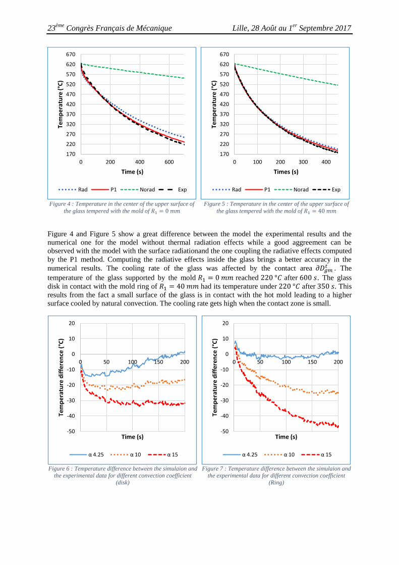
To investigate the sensibility of the convection coefficient value on the numerical results, additional
calculations were performed for the value of . Figure 6 and Figure 7 show
the temperature difference between the experimental data and the numerical results for the glass
cooled with repectively with the disk and the ring molds. The temperature difference increases with
the convection coefficient. For the disk mold case (Figure 6), the maximum temperature error is about
30°C (7% of relative error) for in 200 s whereas the ring case (Figure 7) shows
about 50 °C (15% of relative error). The convection coefficient has the lowest
errors (2.56 % for the disk and 1.39 % for the ring) with the experimental data.
7.2 Stress results
When glass is cooled, a layer near the surfaces is classically submitted to compressive stresses and the
core to tensile stresses [22]. This can be observed in Figure 8 where is shown the distribution of the
circumferential stress in the glass. Due to the presence the hot mold, the contact surface is
not submitted to compressive stresses.
Figure 8: Circumferential residual stress distribution in the glass supported by the mold ring of
The stress distribution through the thickness of a tempered glass is parabolic with compression in the
surface layers and tension in the core. Figure 9 presents the evolution of residual stresses through the
thickness on the axis for the glass in contact with both types of mold (disk and ring).
In the case of the disk mold, tensile residual stresses are observed through the whole thickness along
the axis even in the surface layers. The glass receives heat from the mold at its lower surface. This
reduces the cooling rate in the glass and the surface layers are not cooled fast enough to have
compressive residual stresses. The tensile stresses reached in the core and less than in
the surface layers. It is better to have compressive stresses in the surface because compression closes
small cracks at the surface improving then the mechanical behavior of the glass.
In the case of the glass cooled with the mold of inner radius (ring), the surfaces are
effectively in compression. This is due to the absence contact with the mold near the center of the
glass disk leading to a higher cooling rate by convection. The compressive stresses are about
at the surface while the core is submitted to tension of . To increase the stress level,
forced convection should be used.

23ème
Congrès Français de Mécanique Lille, 28 Août au 1er
Septembre 2017
Figure 9 : Circumferential residual stress ditribution along the thickness in the glass on the axis for the P1 method
7.3 Comparison with the photoelasticity observations with a polariscope
After the cooling of the glass disks to the room temperature, the samples were observed with a circular
polariscope. The principle is to propagate a polarized light through the glass in a direction. The light
leaving the glass vibrates according to the principal stresses contained in the plane perpendicular to the
direction of propagation of the light. In our case the propagation direction is along the revolution axis
of the glass disk.
The phase delay between the principal directions contained in the plane of glass disk is given by [23]:
(27)
Where and are the principal stresses in the plane of the glass disk in cartesian coordinates
system; the photoelastic constant of the glass.
In order to compare the observations of the stress distribution in the glass to the numerical results, a
program was written to compute the phase delay using the stress results from the thermomechanical
model coupled with P1 method. The axisymmetric stress tensor was brought to the Cartesian
coordinates system by rotation, then a numerical integration was performed using trapeze method to
calculate . The comparisons are shown in Figure 10 and Figure 11 respectively for glass tempered
with mold of inner radius and .
a) b) Figure 10 :Comparison of the phase retardation between (a) experimental observations and (b) calculation for the disk mold
-20
-15
-10
-5
0
5
10
15
0 0,002 0,004 0,006
Stre
ss (
MP
a)
Thickness (m)
Disk Ring
23ème
Congrès Français de Mécanique Lille, 28 Août au 1er
Septembre 2017
a) b) Figure 11 : Comparison of the phase retardation between (a) experimental observations and (b) calculation for the ring
The calculated distribution of the phase delay induced by the stress state in the glass is in good
agreement with the experimental observations. In the case of the Figure 11, the phase delay is almost
null inside the zone of the glass disk without contact with the mold ring. This means that the
difference leading to an isotropic stress state in the plane of the glass disk. The difference
between the principal stresses in the same plane is not null for the contact zone. For Figure 10, the
absolute value of the phase delay decreases from the boarder to the center of the glass disk. An
anisotropic stress state inside the glass can be noticed due to the full contact of the lower surface with
the mold.
Conclusion
This paper deals with thermomechanical modeling of the tempering process of a circular glass disk
supported by a metal mold by taking into account radiative effects computed by the P1 method and
experimental investigation of the tempering process.
The comparison between experimental and numerical results shows that thermal radiation takes a great
importance for the heat transfer during the cooling process in natural convection. It can be seen that
the P1 method describes quite well the temperature change of the glass; however, one should note that
it is known to be a diffusive method and can affect the prediction of the stress level. The contact area
also has an influence on the heat transfer. Bigger is the contact zone, more it affects the cooling rate.
The prediction of the distribution of the phase delay induced by the stress state in the glass has good
agreement with the experimental observations. An anisotropic stress state in the glass was observed in
the contact zone. To avoid this anisotropic state, the contact area must be as small as possible. The
high temperature of the mold leads to low stress levels in the glass; therefore experiments with cold
mold should be performed to have a more realistic stress level compared to industrial processes.
References
[1] M. F. Modest, Radiative heat transfer. Academic press, 2013.
[2] J. R. Howell, M. P. Menguc, et R. Siegel, Thermal Radiation Heat Transfer, 5th Edition. CRC
Press, 2010.
[3] W. A. Fiveland, « Discrete-Ordinates Solutions of the Radiative Transport Equation for
Rectangular Enclosures », J. Heat Transf., vol. 106, no 4, p. 699‑ 706, nov. 1984.
[4] J. S. Truelove, « Discrete-Ordinate Solutions of the Radiation Transport Equation », J. Heat
Transf., vol. 109, no 4, p. 1048‑ 1051, nov. 1987.
[5] K. D. Lathrop, « Use of Discrete-Ordinates Methods for Solution of Photon Transport
Problems », Nucl. Sci. Eng., vol. 24, no 4, p. 381‑ 388, avr. 1966.
[6] N. V. Nikonorov, A. K. Przhevuskii, et A. V. Chukharev, « Characterization of non-linear
upconversion quenching in Er-doped glasses: modeling and experiment », J. Non-Cryst. Solids,
vol. 324, no 1‑ 2, p. 92‑ 108, août 2003.
23ème
Congrès Français de Mécanique Lille, 28 Août au 1er
Septembre 2017
[7] W. Zhou et T. Qiu, « Zone modeling of radiative heat transfer in industrial furnaces using
adjusted Monte-Carlo integral method for direct exchange area calculation », Appl. Therm. Eng.,
vol. 81, p. 161‑ 167, avr. 2015.
[8] K. H. Lee et R. Viskanta, « Transient conductive-radiative cooling of an optical quality glass
disk », Int. J. Heat Mass Transf., vol. 41, no 14, p. 2083‑ 2096, juillet 1998.
[9] N. Siedow, D. Lochegnies, F. Béchet, P. Moreau, H. Wakatsuki, et N. Inoue, « Axisymmetric
modeling of the thermal cooling, including radiation, of a circular glass disk », Int. J. Heat Mass
Transf., vol. 89, p. 414‑ 424, oct. 2015.
[10] F. Béchet, N. Siedow, et D. Lochegnies, « Two-dimensional finite element modeling of glass
forming and tempering processes, including radiative effects », Finite Elem. Anal. Des., vol. 94,
p. 16‑ 23, févr. 2015.
[11] H. Loch et D. Krause, Éd., « Mathematical Simulation in Glass Technology », in Mathematical
Simulation in Glass Technology, Berlin, Heidelberg: Springer Berlin Heidelberg, 2002.
[12] R. E. Field et R. Viskanta, « Measurement and Prediction of the Dynamic Temperature
Distributions in Soda-Lime Glass Plates », J. Am. Ceram. Soc., vol. 73, no 7, p. 2047–2053,
1990.
[13] . . arsen, . h mmes, . lar, . ea d, et T. Götz, « Simplified PN Approximations to
the Equations of Radiative Heat Transfer and Applications », J. Comput. Phys., vol. 183, no 2, p.
652‑ 675, déc. 2002.
[14] A. Klar, J. Lang, et M. Seaïd, « Adaptive solutions of -approximations to radiative heat transfer
in glass », Int. J. Therm. Sci., vol. 44, no 11, p. 1013‑ 1023, nov. 2005.
[15] P. Wriggers, Computational contact mechanics: with 12 tables, 2. ed. Berlin: Springer, 2006.
[16] A. Q. Tool et J. Valasek, Concerning the annealing and characteristics of glass. Govt. Print.
Off., 1920.
[17] L. Daudeville et H. Carre, « Thermal tempering simulation of glass plates: inner and edge
residual stresses », J. Therm. Stress., vol. 21, no 6, p. 667–689, 1998.
[18] J. H. Nielsen, J. F. Olesen, P. N. Poulsen, et H. Stang, « Finite element implementation of a glass
tempering model in three dimensions », Comput. Struct., vol. 88, no 17–18, p. 963‑ 972, sept.
2010.
[19] A. Y. Yi et A. Jain, « Compression Molding of Aspherical Glass Lenses–A Combined
Experimental and Numerical Analysis », J. Am. Ceram. Soc., vol. 88, no 3, p. 579‑ 586, mars
2005.
[20] D. Mann, R. E. Field, et R. Viskanta, « Determination of specific heat and true thermal
conductivity of glass from dynamic temperature data », Wärme- Stoffübertrag., vol. 27, no 4, p.
225–231, 1992.
[21] V. A. Narang, « Heat transfer analysis in steel structures », Worcester Polytechnic Institute,
2005.
[22] D. Uhlmann, Elasticity and Strength in Glasses: Glass: Science and Technology. Elsevier, 2012.
[23] G. L. Cloud, Optical methods of engineering analysis. Cambridge: Univ. Press, 1995.