thermoelectric generation using waste heat
TRANSCRIPT
THERMOELECTRIC GENERATORS (TEG)
Presented by: Aman Anand, EEE
THERMOELECTRIC GENERATOR
April/2015
1
2
Introduction
Basic Principle of TEG
Applications
Advantages
Disadvantages
Conclusion
Reference
OVERVIEW
THERMOELECTRIC GENERATOR
Energy crisis-main problem. Increased pollution & population. Tremendous energy wasted in the form of heat. Constant uninterruptable power requirement. Distorts the output performance. Efficiency decreasing in electronic systems. Increased interest in renewable energy. Energy scavengers are modern trend.
SOLUTION???
THERMOELECTRIC GENERATORS
3
THERMO ELECTRIC GENERATOR
INTRODUCTION:
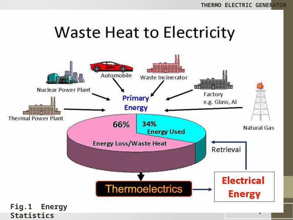
4Fig.1 Energy Statistics
THERMO ELECTRIC GENERATOR
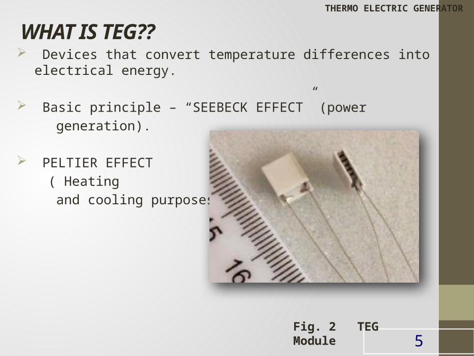
WHAT IS TEG?? Devices that convert temperature differences into electrical energy. Basic principle – “SEEBECK EFFECT” (power generation).
PELTIER EFFECT ( Heating and cooling purposes)
5Fig. 2 TEG Module
THERMO ELECTRIC GENERATOR
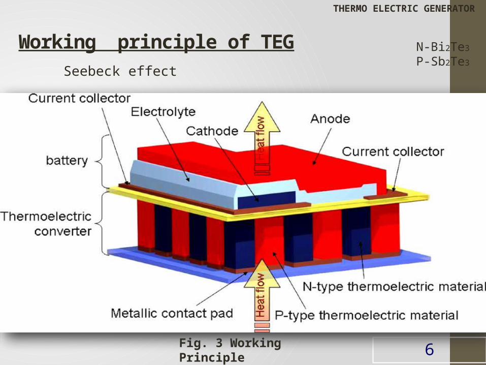
Working principle of TEG Seebeck effect
6Fig. 3 Working Principle
THERMO ELECTRIC GENERATOR
N-Bi2Te3
P-Sb2Te3
THERMO ELECTRIC POWER GENERATION
It is based on SEEBECK EFFECT.
Heat is applied to a circuit at junction of different conductors a current
will be generated.
THOMAS JOHANN SEEBECK invented Seebeck effect in 1822.
The Magnitude of voltage generated is proportional to temperature
difference and depended on type of the conducting material
Seebeck coefficient defined as the open circuit voltage produced between
two points on a conductor when a uniform temperature difference of 1k is
applied between those points.
7
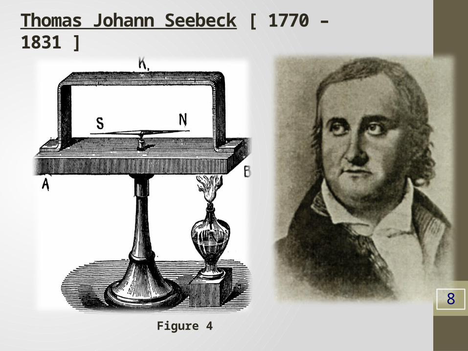
Thomas Johann Seebeck [ 1770 – 1831 ]
8
Figure 4
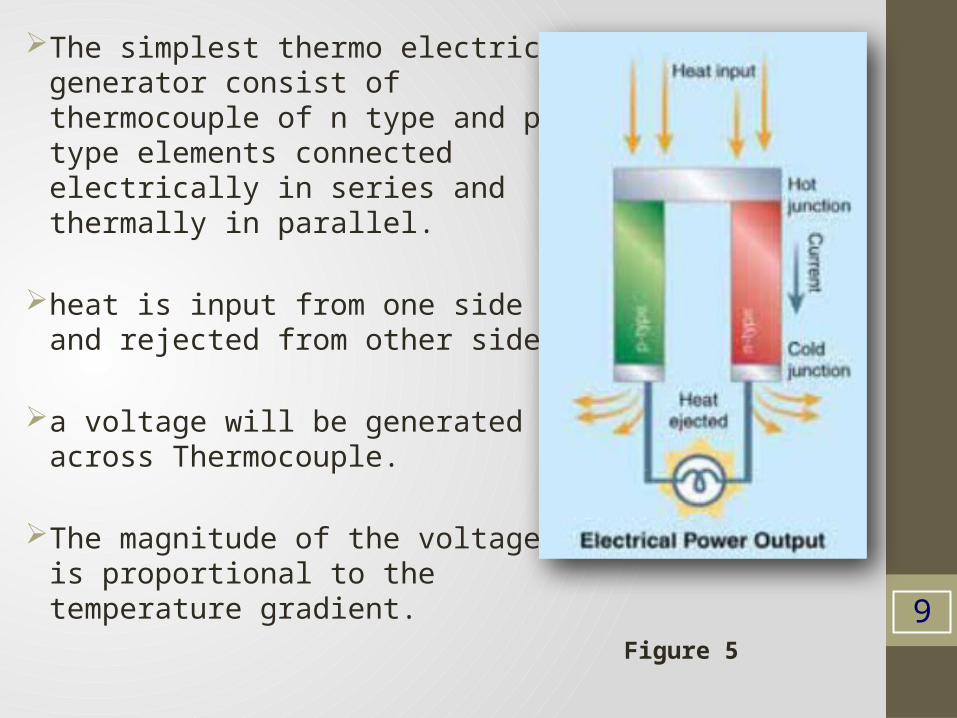
The simplest thermo electric generator consist of thermocouple of n type and p type elements connected electrically in series and thermally in parallel.
heat is input from one side and rejected from other side.
a voltage will be generated across Thermocouple.
The magnitude of the voltage is proportional to the temperature gradient.
9Figure 5
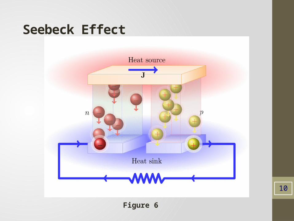
Seebeck Effect
10
Figure 6
THERMO ELECTRIC HEATING AND COOLING
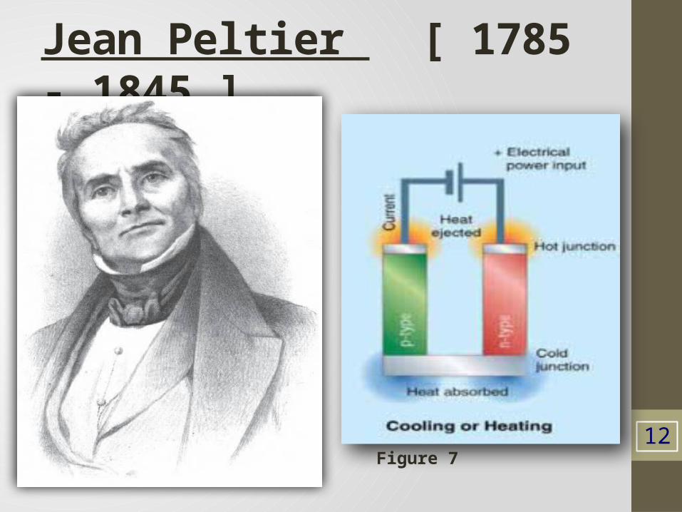
These are based on PELTIER EFFECT That is current is passes through a two dissimilar conductors there will be a
rise or fall of temperature at junction depending on direction of current flow
Peltier effect discovered by Jean Peltier in 1834
Electrons moved from p type to n type, material absorbing thermal energy
from cold junctions.
Electrons dump their extra energy at hot junction as they flow from n type
to p type material through electric connector.
11
Jean Peltier [ 1785 - 1845 ]
12Figure 7
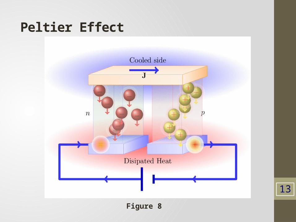
Peltier Effect
13
Figure 8
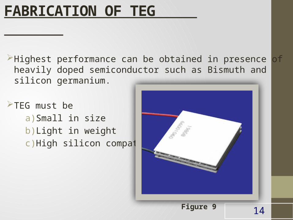
FABRICATION OF TEG
Highest performance can be obtained in presence of heavily doped semiconductor such as Bismuth and silicon germanium.
TEG must be
a) Small in size
b) Light in weight
c) High silicon compatibility.
14Figure 9
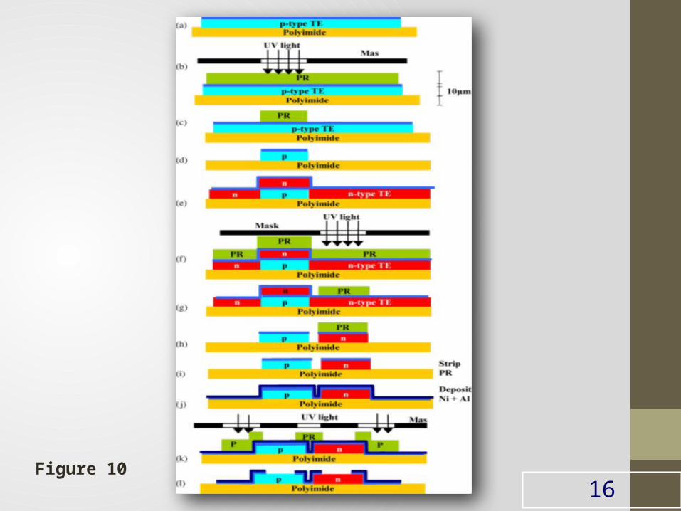
Fabrication process of thermo electric microconverters1. The p type Sb2te3 film is deposited by thermal co-evaporation
followed by Nickel
2. Photo resist and P type elements are patterned by photolithography.
3. Nickel is etched in chromium etchant, a Thermoelectric film is patterned by wet etching HNO3.HCL and photo resist is removed.
4. The n type film deposited by co evaporation followed by 100m nickel layer.
5. Photo resist is applied and patterned by photolithography for n type element.
6. N type is etched in HNO3 and photo resist is removed, contacts are deposited starting with a layer of nickel followed by 1µm of aluminum and photo resist is removed.
7. A protective layer of Si3N4 can also be deposited by low-temperature hot wire chemical vapor deposition and patterned depending on application.
15
16Figure 10
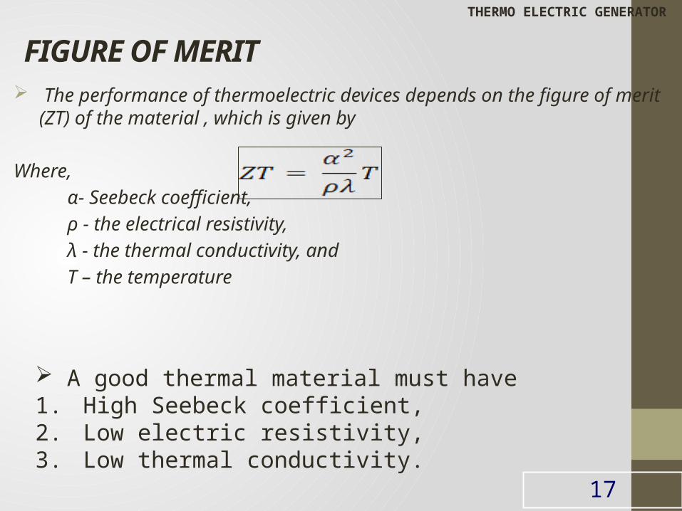
FIGURE OF MERIT The performance of thermoelectric devices depends on the figure of merit (ZT) of
the material , which is given by
Where,
α- Seebeck coefficient,
ρ - the electrical resistivity,
λ - the thermal conductivity, and
T – the temperature
17
THERMO ELECTRIC GENERATOR
A good thermal material must have1. High Seebeck coefficient,2. Low electric resistivity,3. Low thermal conductivity.
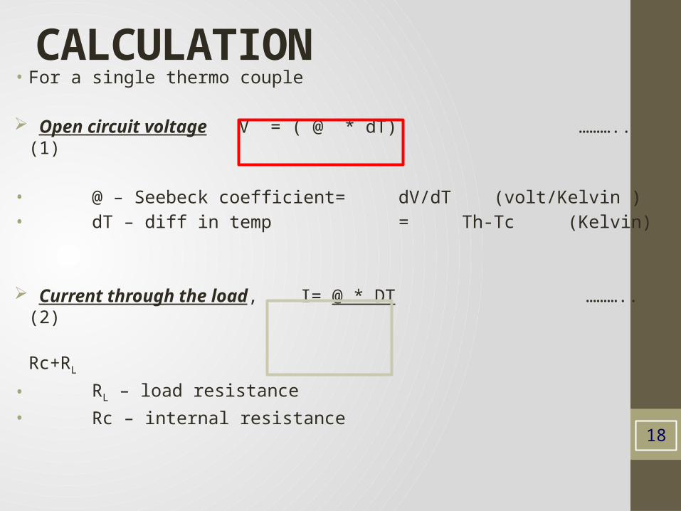
CALCULATION• For a single thermo couple
Open circuit voltage V = ( @ * dT) ……….. (1)
• @ – Seebeck coefficient= dV/dT (volt/Kelvin )• dT – diff in temp = Th-Tc (Kelvin)
Current through the load, I= @ * DT ……….. (2)
Rc+RL
• RL – load resistance
• Rc – internal resistance
18
19
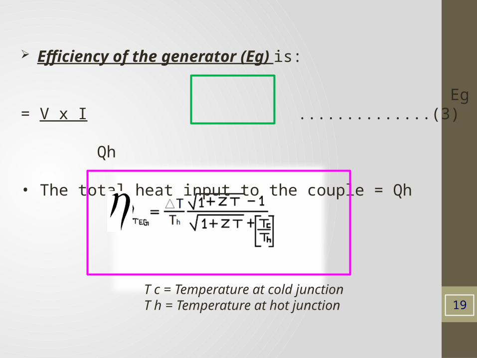
Efficiency of the generator (Eg) is:
Eg = V x I ..............(3) Qh
• The total heat input to the couple = Qh
T c = Temperature at cold junctionT h = Temperature at hot junction
20
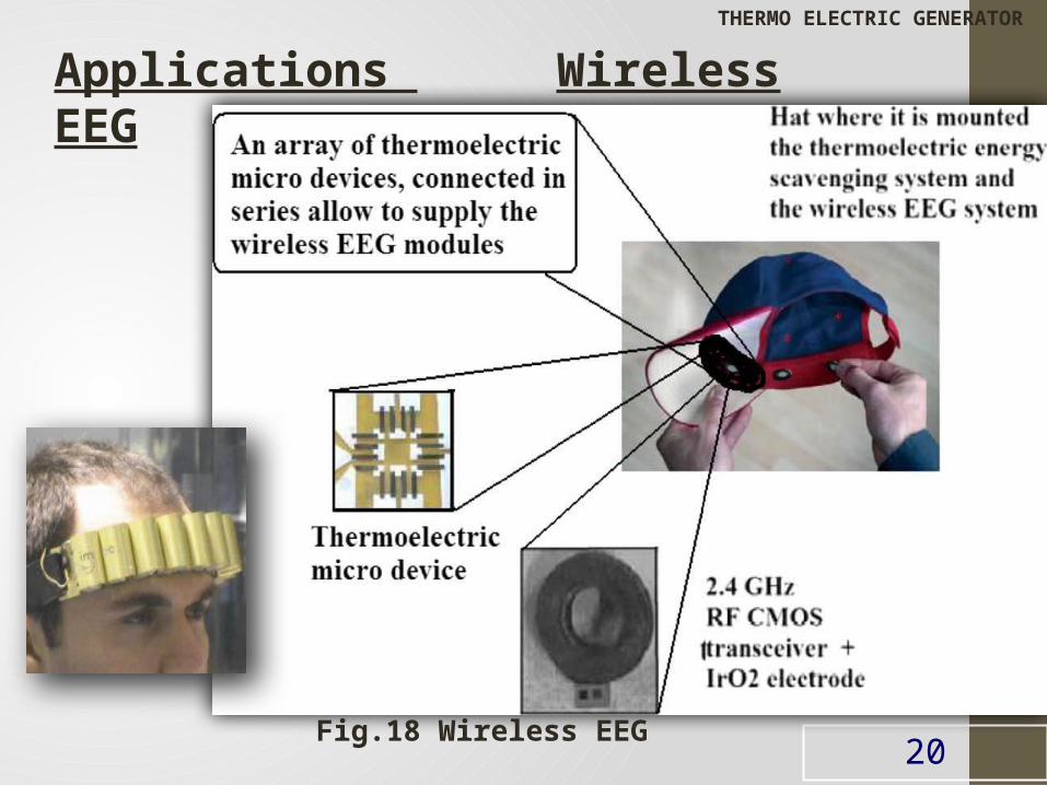
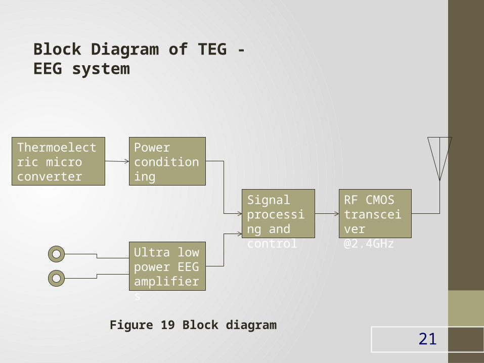
Applications Wireless EEG
Fig.18 Wireless EEG
THERMO ELECTRIC GENERATOR
21
Thermoelectric micro converter
Power conditioning
Ultra low power EEG amplifiers
Signal processing and control
RF CMOS transceiver @2.4GHz
Block Diagram of TEG -EEG system
Figure 19 Block diagram
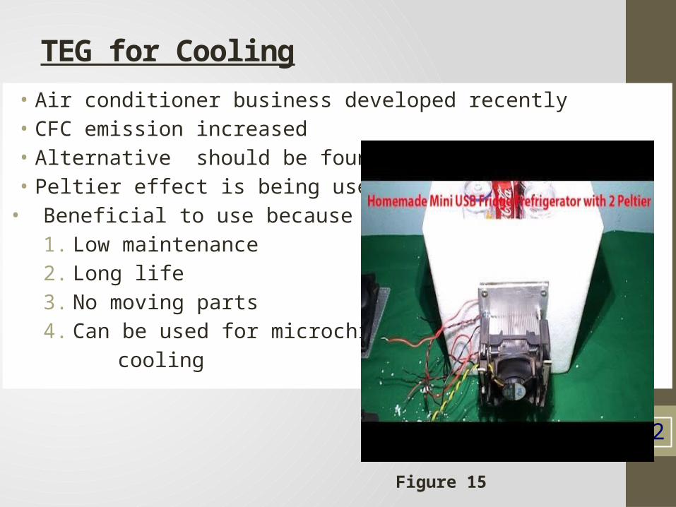
TEG for Cooling• Air conditioner business developed recently• CFC emission increased• Alternative should be found out• Peltier effect is being used
• Beneficial to use because1. Low maintenance2. Long life3. No moving parts 4. Can be used for microchip cooling
22
Figure 15
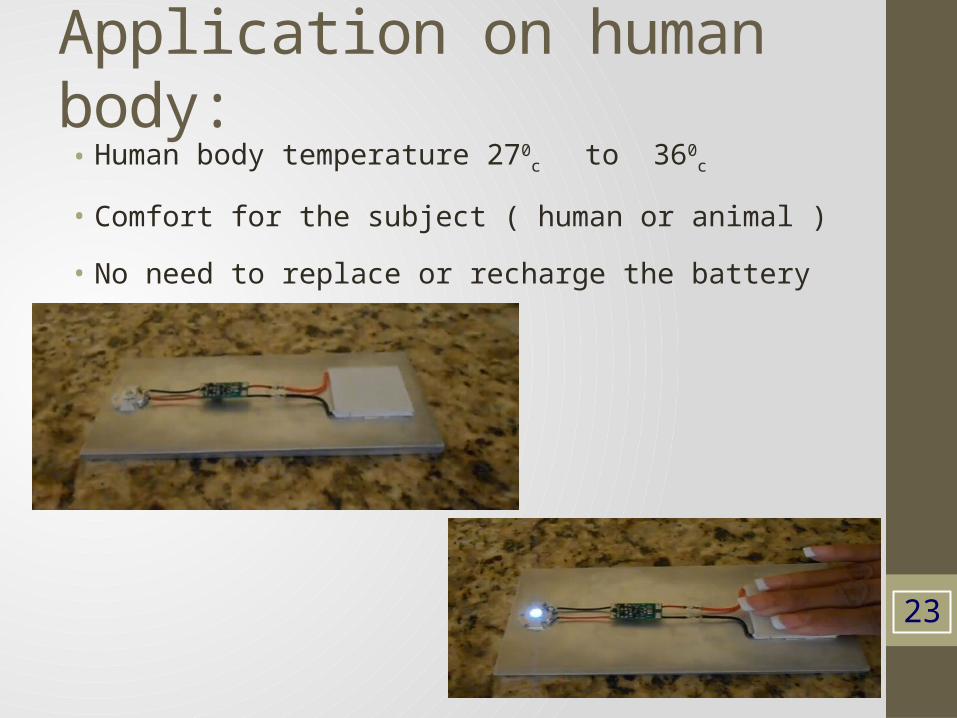
Application on human body:• Human body temperature 270
c to 360
c
• Comfort for the subject ( human or animal )
• No need to replace or recharge the battery
23
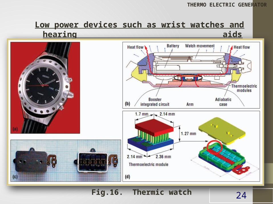
Low power devices such as wrist watches and hearing aids
24Fig.16. Thermic watch
THERMO ELECTRIC GENERATOR
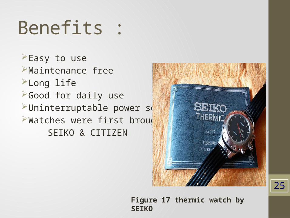
Benefits :Easy to useMaintenance freeLong lifeGood for daily useUninterruptable power so no riskWatches were first brought by SEIKO & CITIZEN
25Figure 17 thermic watch by SEIKO
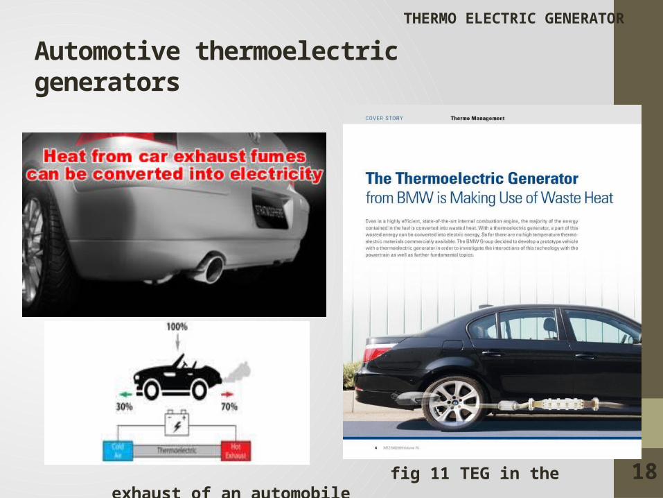
Automotive thermoelectric generators
fig 11 TEG in the exhaust of an automobile
THERMO ELECTRIC GENERATOR
18
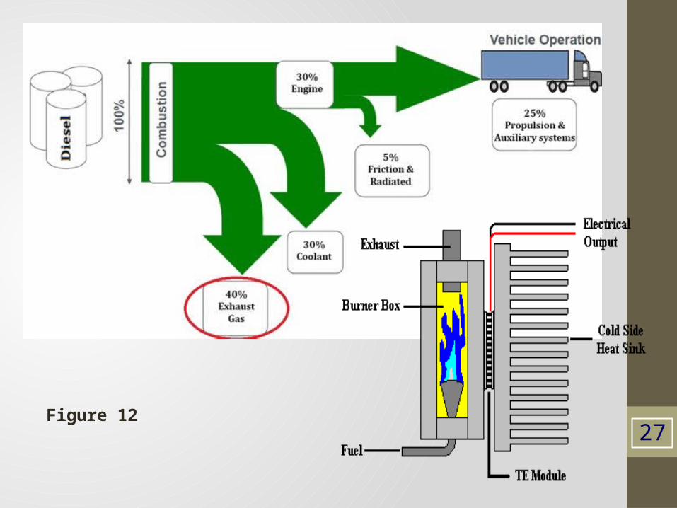
27Figure 12
28
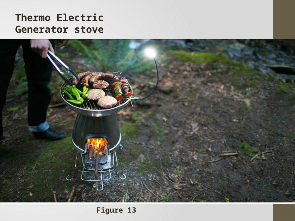
Thermo Electric Generator stove
Figure 13
29
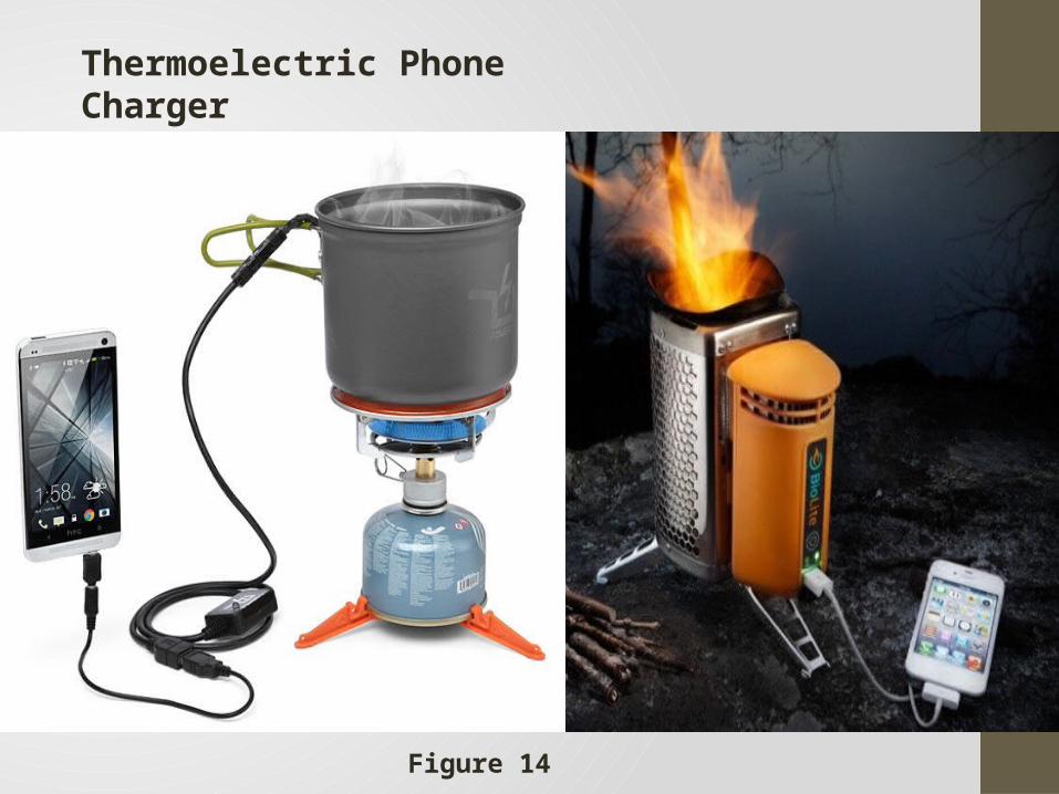
Thermoelectric Phone Charger
Figure 14
Advantages Solid state construction, no moving part, no vibration. Available 24 hours a day. No noise and low maintenance. Convenient power supply. Stabilize temperature of devices. Increase operation life under all environment. Space and military applications. Performance output highly scalable. Waste Heat – Electricity. Space requirement is only 1/20th of a solar cell. Portable power. Less weight than a battery.
30
THERMO ELECTRIC GENERATOR
Disadvantages
Low efficiency.
High cost.
High output resistance.
Adverse thermal conditions.
31
THERMO ELECTRIC GENERATOR
32
ConclusionTHERMO ELECTRIC GENERATOR
TEG to supply low power electronics ( milli watts).
Waste heat conversion to useful energy beneficial to present energy crisis.
Numerous advantages over disadvantages.
Variety of application field.
Introduction of nanotechnology.
Development in future will lead to interesting applications.
E e-books available Google 1. Waste Energy Harvesting: Mechanical and Thermal Energies• By Kong Ling Bing, Tao Li
33
Reference
[1] Joao Paulo Carmo,Luis Miguel Goncalves and Jose Higino Correia, “Thermoelectric microconverter for energy harvesting systems”, IEEE transactions on industrial electronics, VOL. 57, NO. 3, march 2010
[2] Tom Torfs, Vladimir Leonov, Refet Firat Yazicioglu,Patrick Merken, Chris Van Hoof,” Wearable Autonomous Wireless Electro-encephalography System Fully Powered by Human Body Heat”, IEEE SENSORS 2008 Conference.
[3] L.M. Goncalves and J.G. Rocha,” Application of Microsystems Technology in the Fabrication of Thermoelectric Micro-Converters”, Solid State Circuits Technologies, Book edited by: Jacobus W. Swart.
[4] Tianqi Yang, Jinsheng Xiao, Wenyu Zhao, Qingjie Zhang,”Structural Optimization of Two-stage Thermoelectric Generator for Wide Temperature Range Application”,2011 IEEE.
[5] Xiaodong Zhang, C.C. Chan, and Wenlong Li,” An Automotive Thermoelectric Energy System with Parallel Configuration for Engine Waste Heat Recovery”, IEEE trasactions on industrial electronics 2010.
[6] Omer SA, Infield DG. Design and thermal analysis of two stage solar concentrator for combined heat and thermoelectric power generation. Energy Conversion & Management 2000; 41: 737-756.
[7] Design and Fabrication of Heat Storage Thermoelectric Harvesting Devices M. E. Kiziroglou, Member, IEEE, S. W. Wright, T. T. Toh, P. D. Mitcheson, Senior Member, IEEE,Th. Becker and E. M. Yeatman, Fellow, IEEE 2012
34
THERMO ELECTRIC GENERATOR

35
THERMO ELECTRIC GENERATOR
ANY Queries ??

30
THERMO ELECTRIC GENERATOR
Aman Anand