thermodynamics fundamentals for energy conversion...
TRANSCRIPT

Sustainable Energy Science and Engineering Center
Thermodynamics Fundamentals for Energy Conversion Systems
Renewable Energy Applications
The study of the laws that govern the conversion of energy from one form to the other

Sustainable Energy Science and Engineering Center
Energy ConversionConcerned with the transformation of energy from sources such as fossil fuel and radiation from Sun into conveniently used forms such as electrical energy, propulsive energy, heating and cooling.
Forms of energy: Kinetic, potential, thermal, chemical, electromagnetic etc.
Thermodynamics is the study which seeks to establish quantitative relationships among macroscopic variables (like pressure, temperature, molecular concentrations etc.) which describe an arbitrary physical system (system being very large compared with atomic dimensions) in an equilibrium state.
Fuel
Air
Products of combustion
Waste heat to cooling tower
~Electrical energy (Work)
Objective: Convert the availability of the fuel into work in the most efficient manner, taking into consideration cost, size, safety and environmental concerns.
Power plant

Sustainable Energy Science and Engineering Center
Energy Sources and Conversion Processes

Sustainable Energy Science and Engineering Center
Energy Conversion Technologies

Sustainable Energy Science and Engineering Center
Laws of Thermodynamics
The Zeroth Law of Thermodynamics: If two systems are in thermal equilibrium with a third, then they are in thermal equilibrium with each other. This law is the basis of temperature measurement.
First Law of Thermodynamics: The change in internal energy of a closed system is equals to the heat added to the system (or absorbed from the environment) minus the work done by the system (or on the environment). This law is a consequence of conservation of energy. While attempting to transform heat into work with full efficacy, we quickly learned that always some heat would escape into the surrounding environment as wasted energy (recall that energy can not be destroyed). This wasted energy can never be fully converted into anything useful.
Second Law of Thermodynamics: It is impossible to construct an engine which, operating in a cycle, will produce no other effect than the extraction of heat from a single heat reservoir and the performance of an equal amount of work. It imposes a limitation on energy transformations other than that imposed by the first law.
Sustainable Energy Science and Engineering Center
The second law states that heat flows naturally from regions of higher temperature to regions of lower temperature, but that it will not flow naturally the other way.
Heat can be made to flow from a colder region to a hotter region, which is exactly what happens in an air conditioner, but heat only does this when it is forced. On the other hand, heat flows from hot to cold spontaneously.
Entropy is an indicator of the temperature of energy. A given amount of thermal energy has low entropy when it is at high temperature, and the same amount of energy has higher entropy when it is at lower temperature.
Heat is energy, and with energy, size matters. With temperature, it does not.
The radiant energy that arrives at Earth from the Sun at a temperature of 6000 K is a very low-entropy form of heat.
Entropy
Sustainable Energy Science and Engineering Center
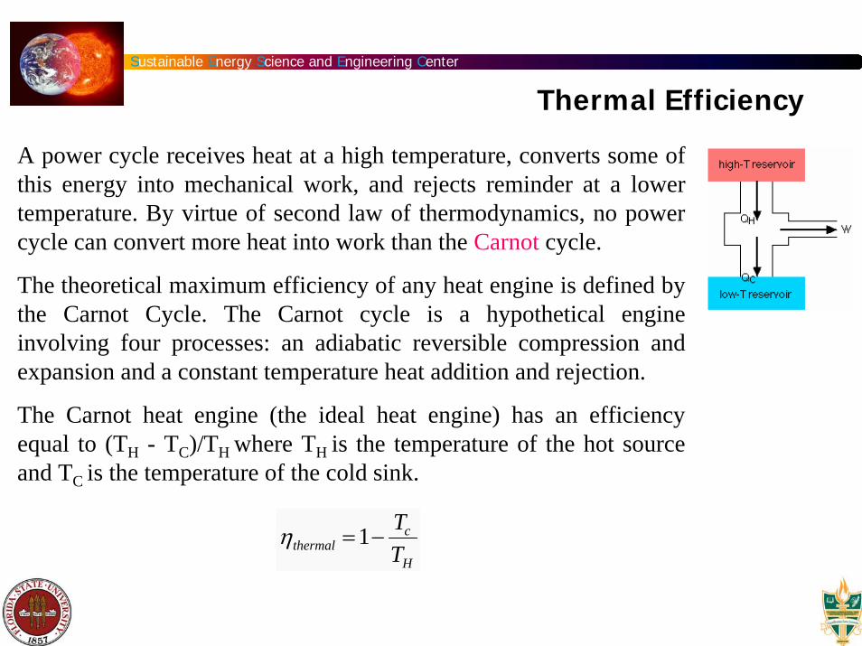
A power cycle receives heat at a high temperature, converts some of this energy into mechanical work, and rejects reminder at a lower temperature. By virtue of second law of thermodynamics, no powercycle can convert more heat into work than the Carnot cycle.
The theoretical maximum efficiency of any heat engine is defined by the Carnot Cycle. The Carnot cycle is a hypothetical engine involving four processes: an adiabatic reversible compression and expansion and a constant temperature heat addition and rejection.
The Carnot heat engine (the ideal heat engine) has an efficiencyequal to (TH - TC)/TH where TH is the temperature of the hot source and TC is the temperature of the cold sink.
Thermal Efficiency
ηthermal =1−Tc
TH

Sustainable Energy Science and Engineering Center
1. Reversible isothermal expansion of the gas at the "hot" temperature, TH.During this step, the expanding gas causes the piston to do work on the surroundings. The gas expansion is driven by absorption of heat from the high temperature reservoir.
2. Reversible adiabatic expansion of the gas.For this step we assume the piston and cylinder are thermally
insulated, so that no heat is gained or lost. The gas continues to expand, doing work on the surroundings. The gas expansion causes it to cool to the "cold" temperature, TC.
3. Reversible isothermal compression of the gas at the "cold" temperature, TC. Now the surroundings do work on the gas, causing heat to flow out of the gas to the low temperature reservoir.
4. Reversible adiabatic compression of the gas.Once again we assume the piston and cylinder are thermally
insulated. During this step, the surroundings do work on the gas, compressing it and causing the temperature to rise to TH. At this point the gas is in the same state as at the start of step 1.
The Carnot Cycle
Sustainable Energy Science and Engineering Center
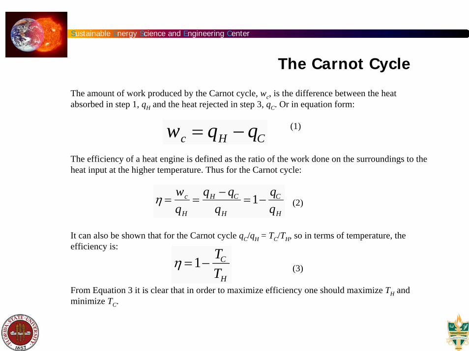
The amount of work produced by the Carnot cycle, wc, is the difference between the heat absorbed in step 1, qH and the heat rejected in step 3, qC. Or in equation form:
(1)
The efficiency of a heat engine is defined as the ratio of the work done on the surroundings to the heat input at the higher temperature. Thus for the Carnot cycle:
(2)
It can also be shown that for the Carnot cycle qC/qH = TC/TH, so in terms of temperature, the efficiency is:
(3)
From Equation 3 it is clear that in order to maximize efficiency one should maximize TH and minimize TC.
wc = qH − qC
η =wc
qH
=qH − qC
qH
=1−qC
qH
η =1−TC
TH
The Carnot Cycle

Sustainable Energy Science and Engineering Center
The Carnot Cycle
Carnot's theorem states that No engine operating between two heat reservoirs can be more efficient than a Carnot engine operating between the same reservoirs. Thus, Equation 3 gives the maximum efficiency possible for any engine using the corresponding temperatures. A corollary to Carnot's theorem states that: All reversible engines operating between the same heat reservoirs are equally efficient. So Equation 3 gives the efficiency of any reversible engine.
In reality it is not practical to build a thermodynamically reversible engine, so real heat engines are less efficient than indicated by Equation 3. Nevertheless, Equation 3 is extremely useful for determining the maximum efficiency that could ever be expected for a given set of thermal reservoirs.
A more useful question to ask is : what is the efficiency when the engine is working at maximum power? A simple analysis will give
ηmax imum− power =1−Tc
TH

Sustainable Energy Science and Engineering Center
The gasses used inside a Stirling engine never leave the engine. There are no exhaust valves that vent high-pressure gasses, as in a gasoline or diesel engine, and there are no explosions taking place. Because of this, Stirling engines are very quiet.
The Stirling cycle uses an external heat source, which could be anything from gasoline to solar energy to the heat produced by decaying plants. No combustion takes place inside the cylinders of the engine.
The key principle of a Stirling engine is that a fixed amount of a gas is sealed inside the engine. The Stirling cycle involves a series of events that change the pressure of the gas inside the engine, causing it to do work.
There are several properties of gasses that are critical to the operation of Stirling engines:
If you have a fixed amount of gas in a fixed volume of space and you raise the temperature of that gas, the pressure will increase.
If you have a fixed amount of gas and you compress it (decrease the volume of its space), the temperature of that gas will increase.
Stirling-cycle engines are among the most efficient practical heat-engines ever built.
Stirling Engine

Sustainable Energy Science and Engineering Center
The simplified engine uses two cylinders. One cylinder is heated by an external heat source, and the other is cooled by an external cooling source. The gas chambers of the two cylinders are connected, and the pistons are connected to each other mechanically by a linkage that determines how they will move in relation to one another.
Stirling Engine
ALPHA-TYPE STIRLING ENGINE

Sustainable Energy Science and Engineering Center
Gamma type Stirling EngineBeta type Stirling Engine
Ref: G. Walker., Stirling Engines, (1980), Oxford Univ. Press.
Stirling Engine

Sustainable Energy Science and Engineering Center
Regenerator: Acts as a thermal barrier between the hot and cold ends of the machine and also store some of the thermal energy. Usually consists of a mesh material and heat is transferred as the working gas is blown through the regeneration mesh. Heat is either deposited or withdrawn from the regenerator depending on the direction the gas is moving.
Thermodynamic Processes in β configuration

Sustainable Energy Science and Engineering Center
Thermodynamic Processes in an Ideal Stirling Cycle
1 2: Isothermal (Constant Temperature) expansion
2 3: Constant volume displacement
3 4: Isothermal compression
4 5: Constant volume displacement

Sustainable Energy Science and Engineering Center
Efficiency of an Ideal Stirling Cycle
W = −mR ln V2
V1
⎛
⎝ ⎜
⎞
⎠ ⎟ TH − TL( )
The equation for work (represents energy out of the system) :
For isothermal expansion process, the heat input is given by:
The efficiency is defined by:
QH = mRTH ln V2
V1
⎛
⎝ ⎜
⎞
⎠ ⎟
η =−WQH
=TH − TL( )
TH
= ηcarnot

Sustainable Energy Science and Engineering Center
1. INTRODUCTION
The Schmidt theory is one of the isothermal calculation methods for Stirling engines. It is the most simple method and very useful during Stirling engine development. This theory is based on the isothermal expansion and compression of an ideal gas.
2. ASSUMPTION OF SCHMIDT THEORY
The performance of the engine can be calculated using a P-V diagram. The volume in the engine is easily calculated by using the internal geometry. When the volume, mass of the working gas and the temperature is decided, the pressure is calculated using an ideal gas method as shown in equation (1).
(1)
The engine pressure can be calculated under following assumptions:(a) There is no pressure loss in the heat-exchangers and there are no internal pressure differences.(b) The expansion process and the compression process changes isothermal.(c) Conditions of the working gas is changed as an ideal gas.(d) There is a perfect regeneration.(e) The expansion dead space maintains the expansion gas temperature - TE, the compression dead space
maintains the compression gas temperature - TC during the cycle.(f) The regenerator gas temperature is an average of the expansion gas temperature - TE and the
compression gas temperature - TC.(g) The expansion space - VE and the compression space - VC changes following a sine curve.
pv = mRT
Stirling Engine Analysis

Sustainable Energy Science and Engineering Center
Stirling Engine Analysis

Sustainable Energy Science and Engineering Center
Alpha-type Stirling Engine
The volumes of the expansion- and compression cylinder at a given crank angle are determined at first. The volumes are described with a crank angle - x. This crank angle is defined as x=0 when the expansion piston is located the most top position (top dead point). The expansion volume - VE is described in equation (2) with a swept volume of the expansion piston -VSE, an expansion dead volume - VDE under the condition of assumption (g).
(2)
The compression volume - VC is found in equation (3) with a swept volume of the compression piston -VSC, a compression dead volume - VDC and a phase angle - dx.
(3)
The total volume is calculated in equation (4).
(4)
By the assumptions (a), (b) and (c), the total mass in the engine - m is calculated using the engine pressure - P, each temperature - T , each volume - V and the gas constant - R.
(5)
VE =VSE
2(1− cos x) + VDE
VC =VSC
21− cos(x − dx){ }+ VDC
V = VE + VR + VC
m =PVE
RTE
+PVR
RTR
+PVC
RTC
Stirling Engine Analysis
Sustainable Energy Science and Engineering Center
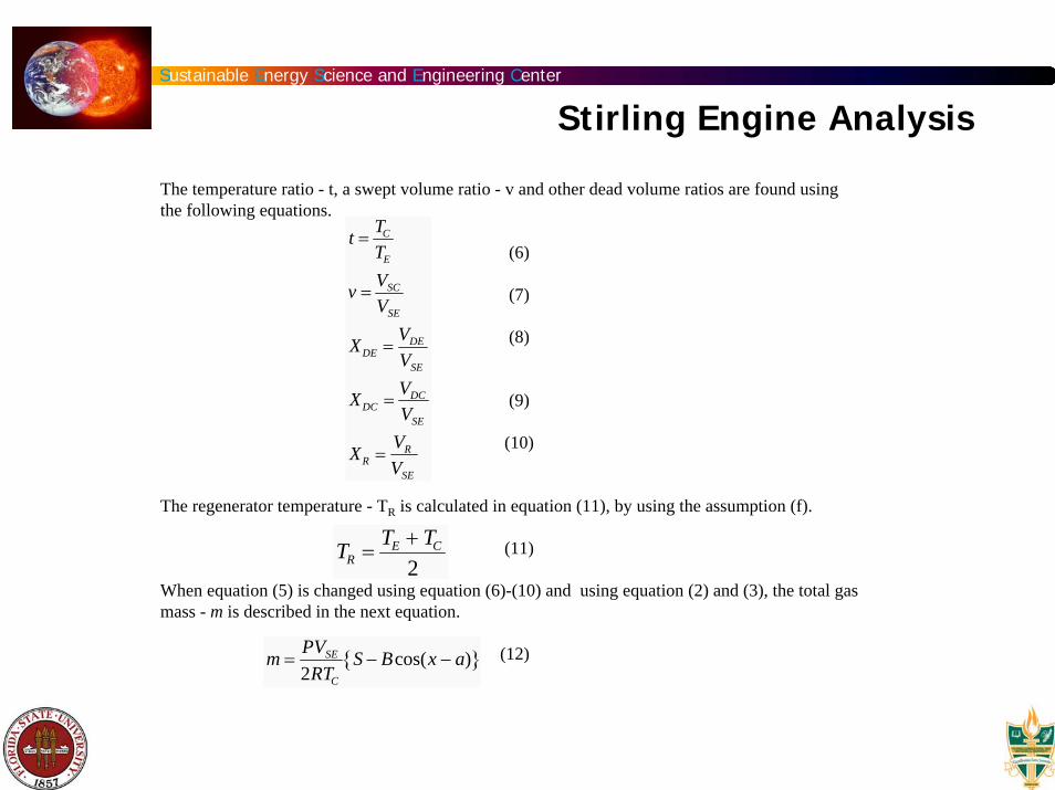
The temperature ratio - t, a swept volume ratio - v and other dead volume ratios are found using the following equations.
(6)
(7)
(8)
(9)
(10)
The regenerator temperature - TR is calculated in equation (11), by using the assumption (f).
(11)
When equation (5) is changed using equation (6)-(10) and using equation (2) and (3), the total gas mass - m is described in the next equation.
(12)
t =TC
TE
v =VSC
VSE
XDE =VDE
VSE
XDC =VDC
VSE
XR =VR
VSE
m =PVSE
2RTC
S − Bcos(x − a){ }
TR =TE + TC
2
Stirling Engine Analysis

Sustainable Energy Science and Engineering Center
Now;
(13)
(14)
(15)
The engine pressure - P is defined as a next equation using equation (12).
(16)
The mean pressure - Pmean can be calculated as follows:
(17)
c is defined in the next equation.
(18)
a = tan−1 v sindxt + cosdx
S = t + 2tXDE +4tXR
1+ t+ v + 2XDC
B = t 2 + 2tv cosdx + v 2
P =2mRTC
VSE S − Bcos(θ − a){ }
Pmean =1
2πPdx∫ =
2mRTC
VSE S2 − B2
c =BS
Stirling Engine Analysis

Sustainable Energy Science and Engineering Center
As a result, the engine pressure - P, based the mean engine pressure - Pmean is calculated in equation (19).
(19)
On the other hand, in the case of equation (16), when cos(x-a)=-1, the engine pressure - Pbecomes the minimum pressure - Pmin, the next equation is introduced.
(20)
Therefore, the engine pressure - P, based the minimum pressure - Pmin is described in equation (21).
(21)
Similarly, when cos(x-a)=1, the engine pressure - P becomes the maximum pressure - Pmax.The following equation is introduced.
(22)
The P-V diagram of Alpha-type Stirling engine can be made with above equations.
P =Pmean S2 − B2
S − Bcos(x − a)=
Pmean 1− c 2
1− c cos(x − a)
Pmin =2mRTC
VSE (S + B)
P =Pmin (1− c)
1− c cos(x − a)
P =Pmax (1− c)
1− c cos(x − a)
Stirling Engine Analysis

Sustainable Energy Science and Engineering Center
3. INDICATED ENERGY, POWER AND EFFICIENCY
The indicated energy (area of the P-V diagram) in the expansion and compression space can be calculated as an analytical solutions with use of the above coefficients. The indicated energy in the expansion space (indicated expansion energy) - WE(J), based on the mean pressure - Pmean, the minimum pressure - Pmin and the maximum pressure - Pmax are described in the following equations.
(23)
The indicated energy in the compression space (indicated compression energy) - WC(J) are described in the next equations.
(24)The indicated energy per one cycle of this engine - Wi(J) is
(25)
WE = PdVE∫ =PmeanVSEπc sina
1+ 1− c 2=
PmaxVSEπc sina1+ 1− c 2
1− c1+ c
WC = PdVC∫ =PmeanVSEπct sin a
1+ 1− c 2=
PmaxVSEπct sin a1+ 1− c 2
1− c1+ c
Wi = WE + WC =PmaxVSEπc(1− t)sin a
1+ 1− c 2
1− c1+ c
Stirling Engine Analysis

Sustainable Energy Science and Engineering Center
The indicated expansion power - LE(W), the indicated compression power - LC(W) and the indicated power of this engine - Li(W) are defined in the following equations, using the engine speed per one second , n(rps, Hz).
(26)
The indicated expansion energy - WE found equation (23) means an input heat from a heat source to the engine. The indicated compression energy - Wc calculated by equation (24) means a reject heat from the engine to cooling water or air. Then the thermal efficiency of the engine - η is calculated in the next equation.
(27)
This efficiency equals that of a Cornot cycle which is the most highest efficiency in every thermal engine.The steady heat transfer from a hot to a cold environment, the time rate of heat transfer may be
represented by
Where A is the surface area of the material that separates the two environments and across which the heat flows and h is the heat transfer coefficient, a property of the material separating the two environments.
η =Wi
WE
=1− t =1−Tc
TE
LE = WE nLC = WC nLi = Win
q•
q•
= hA(TH − TC )
Stirling Engine Analysis

Sustainable Energy Science and Engineering Center
Solar Dish Stirling System
Advnco/Vanguard 25 kW dish/Stirling system installed at Rancho Mirage, California.
The Vanguard concentrator is approximately 11 meters in diameter and made of 366 mirror facets, each facet measures 18 by 24 inches. The engine used is a United Stirling AB (USAB) Model 4-95 Mark II driving a commercial 480 volt/ac 60-Hz alternator.

Sustainable Energy Science and Engineering Center
Solar Dish Stirling System Efficiency

Sustainable Energy Science and Engineering Center
Rankine Cycle Engine
The Rankine cycle based engines are low maintenance alternative in renewable energy applications. The engine uses a heat source, such as concentrated solar radiation, to provide energy to a fluid in a closed cycle. This, in turn, drives a turbine which can be used to produce electricity. This is so called solar Rankine cycle engine.
Geothermal energy application

Sustainable Energy Science and Engineering Center
T
s
3
4
1
2
qin
win qout
wout
η =wturbine − wpump
qin
Rankine Cycle Efficiency
ηth =h1 − h2( )− h4 − h3( )
h1 − h4
Unlike Carnot cycle, the thermodynamic efficiency depends explicitly upon the working fluid properties.

Sustainable Energy Science and Engineering Center
Ideal Reheat Rankine Cycle

Sustainable Energy Science and Engineering Center
Organic Rankine CycleThe ORC technology is based on the Rankine cycle with the difference that instead of water a high molecular mass organic fluid as working medium is used. The selected working fluids allow to exploit efficiently low temperature heat sources (70 to 400oC) to produce electricity.
The organic fluid is vaporized by application of heat source in the evaporator. The organic fluid vapor expands and is then condensed in a heat exchanger. The condensate is pumped back to the evaporator thus closing the thermodynamic cycle.

Sustainable Energy Science and Engineering Center
Temperature Dependence of Rankine Cycle Devices

Sustainable Energy Science and Engineering Center
Cycle efficiencies with Heat engines

Sustainable Energy Science and Engineering Center
Organic Rankine Cycle

Sustainable Energy Science and Engineering Center
ηC =1−Tc
Th
ηi =1−Tc
Th − Th′ln Th
Th′
⎛
⎝ ⎜ ⎜
⎞
⎠ ⎟ ⎟
In many cases, heat will be available only in the form of a heated fluid which cools as energy is extracted from a fluid which cools from Th to Th
’
while giving up heat to the engine. The maximum efficiency is given by the “ideal” efficiency (ηi) , where
Externally Heated Systems

Sustainable Energy Science and Engineering Center
Providing electricity and thermal energy to improve the efficiency of the energy conversion system
1. Generate electricity at the maximum possible efficiency and produce the thermal energy with a separate collector.
2. Generate electricity at the maximum possible efficiency and use a heat engine that would reject heat at the lowest temperature. (generally defines the maximum efficiency)
3. Use a heat engine that would reject heat at high enough temperature to be useful for thermal processes, such as space or water heating.
Cogeneration