thermodynamic fundamentals for the pyrolysis of refuse
TRANSCRIPT

THERMODYNAMIC FUNDAMENTALS FOR THE PYROL YSIS OF REFUSE
F. MICHAEL LEWIS Stanford Research Institute
ABSTRACT
,The purpose of the paper is to discuss the use of pyrolysis for the thermal processing of municipal solid wastes and to make comparisons between pyrolysis systems and conventional waste incineration systems. The terms pyrolysis and gasification are defined, and the thermodynamic principles of refuse pyrolysis processes are developed. Several refuse pyrolysis processes are described and illustrated, including pyrolysis by indirect heating, direct-fired pyrolysis, and pyrolysis with the use or predried refuse. The air pollution aspects of pyrolysis are discussed and compared with those
,
of other thermal processes. Finally a thermo-dynamic comparison based on a process cost/process credit ratio is made between pyrolysis systems and conventional systems for the thermal processing of municipal solid wastes. •
INTRODUCTION
The use of pyrolysis in thermal processing of municipal solid waste has generated a great deal of interest. Compared with some existing incineration techniques, pyrolysis can be more effective in reducing the mass, bulk, and putrescibility of the solid waste and has more potentiality for increasing resource recovery and decreasing air pollution.
Pyrolysis is the term used for an irreversible chemical change brought about by the action of heat in an atmosphere devoid of oxygen. Synonymous terms are thermal decomposition, destructive distillation, and carbonization.
1 9
The pyrolysis of organic compounds yields: .Char • Organic liquids (pyroligneous acids) • Fuel gas • Water (present in either liquid or gaseous state
depending on final pyrolysis conditions). The char contains any mineral ash or other non
combustible material present in the waste plus what is termed the "fixed carbon," which represents the carbonaceous fraction of the original material that did not volatilize on heating. The char also usually contains small quantities of hydrogen and oxygen, and nitrogen is sometimes present.
The organic liquids are a complex mixture of chemicals and are often called pyroligneous acids, because they are acidic and were first produced by the destructive distillation of wood. The fuel gas consists of a number of combustible gases, such as carbon monoxide, methane, hydrogen, ethylene, and minor quantities of other, higher hydrocarbons. The fuel gas also contains an appreciable quantity of carbon dioxide and may contain water vapor if it has not been previously condensed out of the stream.
Some recently developed systems for thermal processing of municipal solid waste are called pyrolysis but are, in fact, more closely related to gasification. Literally, gasification means to convert a solid or liquid substance to a gas. Specifically, the term refers to the oxidation-reduction reactions that convert carbonaceous solids to combustible gas products. The gas producer is a furnace specifically designed for the gasification process to make a combustible, gaseous fuel from a variety of

carbonaceous materials, such as bituminous coal, charcoal, and coke, by reaction with steam and steam/air mixtures.
Because both of these processes have become accepted as pyrolysis, they have been included in the discussion, but under the following definitions:
Pyrolysis - Thermal processing of waste in the absence of oxygen, in (a) indirectly heated retorts, and (b) furnaces that are directly heated by flue gases from a burner firing on a stoichiometric air /fuel ratio.
Gasification - Thermal processing of waste, where a fraction of the stoichiometric oxygen required by the waste is admitted directly into the fuel bed to liberate the heat required for endothermic gasification reactions. The volatile portion of incoming waste will be pyrolyzed by the heat of the fuel gases, and the outlet gas composition will reflect both processes.
In the laboratory, pyrolysis processes for municipal solid waste have been developed to produce chemical feedstocks, liquid boiler fuels, activated carbon, and fuel gas for steam generation. This discussion deals primarily with municipal waste pyrolysis for steam generation.
One of the primary advantages of pyrolysis is that the combustion of the fuel gases takes place in a chamber physically separated from the solid waste so that combustion can be completed at high temperatures and low excess air for maximum thermal efficiency.
REFUSE COMPOSITION
A baseline refuse composition must be established before a thermal process for municipal solid waste can be analyzed or compared with other processes, and the following composition has been assumed here:
Moisture Inerts (Ash) Combustibles
Carbon Hydrogen Oxygen
25 percent 25 percent 5 0 percent
52 percent 7 percent
41 percent
Higher Heating Value (HHV) - 4,750 Btu/lb (2,634 Kg-cal/Kg)
For easier calculations, the refuse is assumed free of nitrogen, sulfur, chlorine, and other elements and compounds usually found in trace amounts.
20
THERMODYNAMIC FUNDAMENTALS
PROCESS VARIABLES
The ultimate yield and final composition of the solid, liquid, and gaseous products from pyrolysis and gasification depend on a number of process variables. For pyrolysis processes, the major variables are the chemical composition of the raw materials, heating rate, and ultimate temperature. Several studies [1,2,3,4,5] of these and other process parameters lead to the conclusion that the complexity of these interactions makes it impossible to predict the final product characteristics.
ENDOTHERMIC AND EXOTHERMIC
PROCESSES
A pyrolysis process may be endothermic (require heat) or exothermic (give up heat), depending on the ultimate temperature reached. In most materials, the process is endothermic at lower temperatures and exothermic at higher temperatures. In all cases, the heating value of the pyrolysis products is the sum of the heating value of the original material and the net energy added during pyrolysis. In many cellulosic materials, the amount of energy absorbed or liberated by the pyrolysis reaction is very small compared with the heating value of the original materiai. Unfortunately, in most pyrolysis studies performed to date, the emphasis has been on identification of the many complex chemicals generated by pyrolysis rather than on heat and material balances for pyrolysis processes, for which very few data are available.
However, since the heating value of the pyrolysis product is always equal to the heating value of the original material plus any heat added, a heat and material balance can be performed based on review of the available data. [6,7]
THERMODYNAMIC SYSTEM BOUNDARY
To perform a thermodynamic analysis, a Thermodynamic System Boundary must be drawn around the system to be analyzed. Figure 1 shows a typical thermal processing system for municipal solid waste, which can be either a pyrolysis or an incineration system. The thermodynamic system boundary is indicated for all systems analyzed.
In these analyses, the system boundary has been considered to end up-stream of any air pol-
•

•
Flue G.
ITHERMOOYNAMIC
I SYSTEM BOUNDARY
I I TYPICAL THERMAL
I PROCESSING SYSTEM
I W.ste
PYROLYSIS Combustion Air OR
INCINERATION
Auxiliary Fu.1
I I L -
Ash
I I I I Materl.1 Entering
Thermodynamic
I System Boundary
I I I I I I
-�
He.t Entering Thermodynemic
Sy.t.m Bound.ry
M.t.ri.1 L ..... inQ - Thermodynemic
System Boundary
Hilt L ..... ing ., Thermodyn.mic
System Bound.ry
FIG.l TYPICAL THERMAL PROCESSING SYSTEM
lution control device. Also, zero heat loss for the systel\ls analyzed has been assumed, because the purpose is to illustrate a methodology and to make comparisons with other processes. Assuming a heat loss of, say, 5 percent of the refuse heat input would not serve any particular purpose.
HEAT AND MATERIAL BALANCE
The comparative analyses developed are based on a balance of the material and heat inputs and outputs (Heat and Material Balance):
Material in = Material out Heat in = Heat out
These balances provide a valuable tool that should always be used in the·coll1parative evaluation of thermal processing systems.
In a thermodynamic analysis, material and heat are accounted for only when they cross the thermodynamic system boundary. Internal recycle loops, if they are present, do not affect the overall heat and material balance.
PYROLYSIS PROCESS -INDIRECTLY
HEATED ROTARY KILN
Pyrolysis processes vary. In the process considered in this paper, the refuse has been indirectly heated in a retort completely devoid of oxygen. Figure 2 gives a cross section of a typical indirectly heated rotary kiln. The cylindrical retort section of
21
this kiln is inclined slightly and rotated slowly, causing the refuse to move from the front end to the discharge end of the retort. The retort is enclosed in a refractory-lined firebox. A portion of the pyrolysis fuel gas is burned in the annular space between the outside well of the cylindrical retort and the interior of the firebox. Heat is transferred through the alloy metal wall of the retort to pyrolyze the refuse. This type of retort will require shredded refuse that can pass through a screen with two-inch openings.
Because of the complexity of the pyrolysis process, complete data of the accuracy and detail that would be required to perform a detailed heat and material balance around the pyrolysis process are not available. However, by use of reported experimental data, [1, 2, 3] a balance can be developed. The composition of the dry fuel gas from this developed balance is:
Component
CO2 CO CH4 H2 C2H4
Volume Percent
19.6 35 .0 20.4 16.3
8.7
The organic liquids can be represented by the chemical formula developed by Kaiser: [I]
The assumed heating value of this organic liquid is 14,000 Btu/lb (HHV) (7,778 Kg-cal/Kg).

Re
fuse
IV
Feed
IV
I •
1t!
!�_l;)· . ..:."
.-9· �.
r .1'\-.
-....
I I I
RE
CY
CL
E
FU
EL
G
AS
•
�
� I
'"
".
t I
'(/A
V.J"I
t . -
�
I F
IRE
BO
X
� I I
PY
RO
L Y
SIS
R
EA
CT
OR
(R
ET
OR
T)
,
.... I�
FU
EL
G
AS
./
/
I
,.
BU
RN
ER
�
FIG
.2
•
CO
MB
US
TIO
N
AIR
IND
IRE
CT
LY
HE
AT
ED
, R
OT
AR
Y K
ILN
P
YR
OL
IZE
R
•
•
t T
-,
� (
\ \�.
t,l
",
"''1 F
UE
L
._
G
AS
I%J t
Ch
ar
Disc
ha
rge
To
C
om
bu
stio
n
Sy
ste
m/B
oil
er

The assumed composition of the carbonaceous fraction of the char is:
Component
Carbon Hydrogen Oxygen
Weight Percent
85 2
13
The assumed heating value of the carbonaceous fraction is 13,000 Btu/lb (HHV) (7,222 Kg-cal/Kg).
A detailed heat and material balance for the pyrolysis process based on the assumed composition of the pyrolysis products is shown in Tables 1 and 2* .
In an actual pyrolysis process, where the objective is to produce steam, the organic liquids will exit with the pyrolysis gas in an aerosol, and the aerosol will burn along with the combustible gases. The pyrolyzer exhaust temperature of I 400°F (760°C) will prevent condensation of the aerosol if the lines are properly insulated between the reactor and the burner. Table 3 shows a material balance for combustion of the pyrolysis gases at 20 per-cent excess air. The char from this process has not been combusted.
The heating value of the pyrolysis products will always be equal to the value of the original material plus any heat added. Such a detailed analysis of the composition of the pyrolysis gases and the associated heat and material balance surrounding that portion of the pyrolysis is not necessary to perform an overall heat and material balance, but has been included for illustrative purposes.
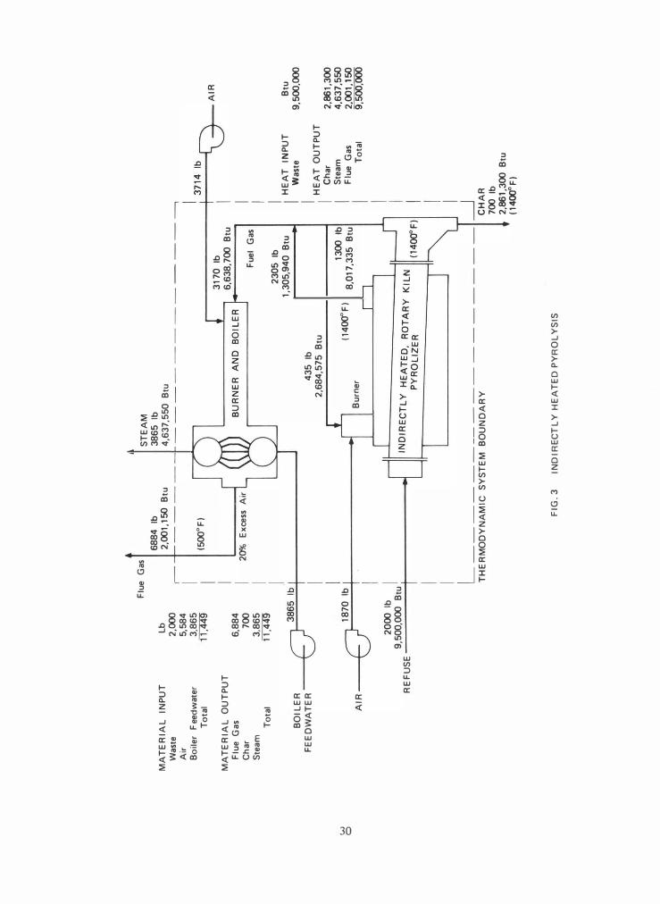
PYROLYSIS SYSTEM DESIGNED FOR STEAM
PRODUCTION
A typical pyrolysis system incorporating the indirectly heated, pyrolysis fuel gas-fired rotary kiln is shown in Figure 3. The quantity of pyrolysis fuel gas that has been recycled back to the retort to sustain the process has been indicated but, as shown in the figure, does not influence the over-all heat balance. The system has been designed to produce steam, and the selected boiler exhaust temperature is 500°F (260°C).
'In all the tables and figures presented in this paper, the numerical values are shown to more-than-significant figures, merely for clarity and ease of figuring and not with the intent of implying an equivalent degree of . . precIsion.
23
Conventional afterburners represent combustion units that were originally designed to incinerate gases from solvent evaporation processes, and in general, the heating value of the gases intrad uced into these units was of the order of 8 to 15 BtU/ft3 (71 to 133 Kg-cal/m3). In the pyrolysis system described here, the fuel gas heating value is approximately 300 BtU/ft3 (2,669 Kg-cal/m3). Whenever the heating value of a fume or fuel gas approaches 50 Btu/ft3 (445 Kg-cal/m3), the combustion process becomes self-sustaining; hence, the gas should be burned in a burner of the type used for coke oven gas and carbon-baking processes [8] .
A burner of this type can be readily adapted to a conventional boiler.
The theoretical flame temperature at 20 percent excess air for the pyrolysis gases from this process is approximately 3,000°F (I ,649°C). If control of nitrogen oxides becomes necessary, staged combustion [6] may be advisable. In all cases, the burner should fire into a boiler that has a
radiation section to absorb some heat and reduce the temperature of the flue gas to approximately I ,600°F (871 ° C) before the gas enters a convection bank, to minimize slagging of the boiler tubes.
PYROLYSIS WITH PREDRIED REFUSE
In discussions of pyrolysis processes, predrying of the refuse is mentioned as a means of improving the thermal efficiency of the process. However, it can be shown that thermal efficiency cannot be improved by this method without violating the First Law of Thermodynamics.
A hypothetical refuse pyrolysis system with refuse drying is shown in Figure 4. The refuse is dried to zero moisture content in a direct-contact dryer using 500°F (260°C) boiler exhaust gases. These gases pick up the refuse moisture and leave the dryer at 300°F (I 49°C). The solid portion of the refuse has been heated to 25 0°F (I21 0C). Some pyrolysis of the low boiling fractions will occur even at temperatures as low as 500°F (260°C), and the flue gases will contain trace quantities of pyrolysis products. Some odoriferous constituents will also be present in the flue gases. The flue gases are taken to the burner section for reburning to eliminate these odors.
This system produces the same amount of steam and discharges the same quantity of flue gases as the system not using predried refuse. No increase has occurred in thermal efficiency, i.e., in the quantity of steam produced.

TA
BL
E 1
P
YR
OL
YS
IS M
AT
ER
IAL
BA
LA
NC
E
(1 T
on
of
Was
te)
Ca
rb
on
H
yd
ro
ge
n
Ox
yg
en
I
ne
rt
s
To
ta
l
---
Ib
Ib
Ib
Ib
Ib
In
pu
t
Co
mb
us
ti
bl
es
5
20
.0
7
0.
0
41
0.
0
1,
00
0.
0
Mo
is
tu
re
5
5.
6
44
4.
4
50
0.
0
In
er
ts
5
00
.0
5
00
.0
--
---
-
To
ta
l
52
0.
0
12
5.
6
85
4.
4
50
0.
0
2,
00
0.
0
Ou
tp
ut
Ch
ar
1
70
.0
4
.0
2
6.
0
50
0.
0
70
0.
0
tv
Or
ga
ni
c
li
qu
id
s
(C6
H8
O)
21
3.
9
23
.8
4
7.
3
28
5.
0
�
Fu
el
Ga
s
Ca
rb
on
d
io
xi
de
(C
O2
) 2
8.
9
77
.1
1
06
.0
Ca
rb
on
m
on
ox
id
e
(CO
) 5
1.
5
68
.5
1
20
.0
Me
th
an
e
(CH
4)
30
.0
1
0.
0
40
.0
Hy
dr
og
en
(H
2)
4.
0
4.
0
Et
hy
le
ne
(C
2H
4)
25
.7
4
.3
3
0.
0
Su
bt
ot
al
1
36
.1
1
8.
3
14
5.
6
30
0.
0
Wa
te
r
va
po
r
Wa
st
e
mo
is
tu
re
5
5.
6
44
4.
4
50
0.
0
Py
ro
ly
si
s
23
.9
1
91
.1
2
15
.0
--
-
Su
bt
ot
al
7
9.
5
63
5.
5
71
5.
0
To
ta
l
52
0.
0
12
5.
6
85
4.
4
50
0.
0
2,
00
0.
0

TA
BL
E 1
(S
I U
NIT
S)
PY
RO
L Y
SIS
MA
TE
RIA
L B
AL
AN
CE
(9
07
.2 K
g)
Ca
rb
on
Hy
dr
ogen
O
xygen
In
ert
s T
ot
al
Inp
ut
K
g
Kg
K
g
Kg
K
g
Co
mb
us
ti
bl
es
23
5.
9
31
.7
1
86
.0
4
53
.6
Mo
is
tu
re
25
.2
2
01
.6
2
26
.8
Iner
ts
22
6.
8
22
6.
8
--
Tot
al
2
35
.9
5
6.
9
38
7.
6
22
6.
8
90
7.
2
Out
put
Ch
ar
7
7 .
1
1.
8
11
.8
2
26
.8
3
17
.5
IV
Or
ga
ni
c 1i
qui
d�
(C6
H8
0)
97
.0
1
0.
8
21
.5
1
29
.3
Ul
Fue
l
Ga
s
Ca
rb
on d
io
xi
de
(CO
2)
13
.1
3
5.
0
48
.1
Ca
rb
on
mon
oxi
de
(CO
) 2
3.
3
31
.1
5
4.
4
Met
ha
ne
(CH
4)
13
.7
4
.5
1
8.
2
Hy
dr
ogen
(H
2)
1.
8
1.
8
Et
hy
len
e (C
2H
4)
11
.7
1
.9
1
3.
6
Sub
tot
al
6
1.
7
8.
2
66
.1
1
36
.1
Wa
ter
v
ap
or
Wa
st
e m
oi
st
ur
e 2
5.
2
20
1.
6
22
6.
8
Pyr
ol
ys
is
1
0.
9
86
.6
9
7.
5
--
Sub
tot
al
3
6.
1
28
8.
2
32
4.
3
To
ta
l
23
5.
8
56
.9
3
87
.6
2
26
.8
9
07
.2

In
pu
t
Co
mb
us
ti
bl
e
Ex
te
rn
al
ly
s
up
pl
ie
d
To
ta
l
Ou
tp
ut
Ch
ar
Or
ga
ni
c
li
qu
id
s
(C6
HS
O)
N
0\
Fu
el
g
as
Ca
rb
on
d
io
xi
de
(C
O2
)
Ca
rb
on
m
on
ox
id
e
(CO
)
Me
th
an
e
(CH
4)
Hy
dr
og
en
(H
2)
Et
hy
le
ne
(C
2H
4 )
Su
bt
ot
al
Wa
te
r
va
po
r
Wa
st
e
Py
ro
ly
si
s
Su
bt
ot
al
To
ta
l
TA
BL
E 2
P
YR
OL
YS
IS H
EA
T B
AL
AN
CE
(1 T
on o
f W
aste
; 1
40
0°F
)
Se
ns
ib
le
La
te
nt
Bt
u
Bt
u
1,
37
8,
63
5
1,
37
8,
63
5
26
1,
30
0
19
0,
95
0
71
,2
50
37
,0
70
42
,5
15
43
,7
60
18
,9
15
26
,1
30
16
8,
39
0
32
7,
50
0
53
0,
00
0
14
0,
82
5
22
7,
90
0
46
8,
32
5
75
7,
90
0
1,
08
8,
96
5
82
9,
15
0
Ch
em
ic
al
T
ot
al
--
-
Bt
u
Bt
u
9,
50
0,
00
0
9,
50
0,
00
0
1,
37
8,
63
5
9,
50
0,
00
0
10
,8
78
,6
35
2,
60
0,
00
0
2,
86
1,
30
0
3,
99
0,
00
0
4,
25
2,
20
0
37
,0
70
52
1,
64
0
56
4,
15
5
95
5,
16
0
99
8,
92
0
24
4,
40
0
26
3,
31
5
64
9,
32
0
67
5,
45
0
2,
36
0,
52
0
2,
53
8,
91
0
85
7,
50
0
36
8,
72
5
1,
22
6,
22
5
8,
94
0,
52
0
10
,8
78
,6
35

Inp
ut
Co
mb
ust
ib
le
Ex
te
rn
al
ly
su
pp
li
ed
To
ta
l
Ou
tp
ut
Ch
ar
N
Or
ga
ni
c l
iq
ui
ds
(C
6H
8O
) -l
Fue
l
ga
s
Ca
rb
on
d
io
xi
de
(C
O2
)
Ca
rb
on
m
on
ox
id
e
(CO
)
Me
th
an
e
(CH
4)
Hy
dr
og
en
(H
2)
Et
hy
le
ne
(C
2H
4)
Sub
to
ta
l
Wa
te
r v
ap
or
Wa
st
e
Pyr
ol
ys
is
Su
bt
ot
al
To
ta
l
TA
BL
E 2
(S
I U
NIT
S)
PY
RO
LY
SIS
HE
AT
BA
LA
NC
E
(90
7 Kg
; 76
0°C
)
Sen
sib
le
L
at
en
t
Kg
-ca
l
Kg
-ca
l
34
7,
38
8
34
7,
38
8
65
,8
42
48
,1
16
1
7,
95
3
9,
34
1
10
,7
13
11
,0
27
4,
76
6
6,
58
4
42
,4
31
82
,5
24
1
33
,5
49
35
,4
85
5
71
42
6
11
8,
00
9
19
0,
97
5
27
4,
39
8
20
8,
92
8
Che
mi
cal
T
ot
al
K
g-
cal
K
g-
cal
2,
39
3,
81
0
2,
39
3,
81
0
34
7,
38
8
2,
39
3,
81
0
2,
74
1,
19
8
65
5,
14
8
72
0,
9�
0
1,
00
5,
40
0
1,
07
1,
46
9
9,
34
1
13
1,
44
3
14
2,
15
6
24
0,
68
1
25
1,
70
8
61
,5
84
6
6,
35
0
16
3,
61
6
17
0,
20
0
59
7,
32
4
63
9,
75
5
21
6,
07
3
92
19
11
30
8,
98
4
2,
25
7,
87
2
2,
74
1,
19
8

•
IV
00
In
pu
t
Py
ro
ly
si
s
ga
se
s
CO
2
CO
CH
4
H2
C2
H4
Or
ga
ni
c
li
qu
id
s
(C
H
0)
6
8
Wa
te
r
va
po
r
Py
ro
ly
si
s
Wa
st
e
Ai
r
To
ta
l
Ou
tp
ut
CO
2
N 2
°2
H2
O
To
ta
l
TA
BL
E 3
M
AT
ER
IAL
BA
LA
NC
E -
CO
MB
US
TIO
N O
F
PY
RO
LY
SIS
PR
OD
UC
TS
AT
20%
EX
CE
SS
AIR
Ca
rb
on
lb
28
.9
51
.5
30
.0
25
.7
21
3.
9
35
0.
0
35
0.
0
35
0.
0
Hy
dr
og
en
lb
10
.0
4.
0
4.
3
23
.8
23
.9
55
.6
12
1.
6
12
1.
6
12
1.
6
Ox
yg
en
lb
77
.1
68
.5
47
.3
19
1.
1
44
4.
4
1,
29
2.
8
2,
12
1.
2
93
3.
4
21
5.
5
97
2.
3
2,
12
1.
2
Ni
tr
og
en
lb
4,
29
1.
4
4,
29
1.
4
4,
29
1.
4
4,
29
1.
4
To
ta
l
lb
10
6.
0
12
0.
0
40
.0
4.
0
30
.0
28
5.
0
21
5.
0
50
0.
0
5,
58
4.
2
6,
88
4.
2
1,
28
3.
4
4,
29
1.
4
21
5.
5
1,
09
3.
9
6,
68
4.
2

tV
\0
Inpu
t
Pyro
lysi
s ga
ses
C02
CO
CH4
H 2 C 2H 4 Or
gani
c li
quid
s (C
6H 8O)
Wate
r va
por
Pyro
lysi
s
Wast
e
Air
Tota
l
Outp
ut
CO2
N 2 °2
H 2O
Tota
l
•
TA
BL
E 3
(S
I U
NIT
S)
MA
TE
RIA
L B
AL
AN
CE
-C
OM
BU
ST
ION
OF
PY
RO
LY
SIS
PR
OD
UC
TS
AT
20
% E
XC
ES
S A
IR
Carb
on
Kg
13.1
23.4
13.6
11.7
97.0
158.
8
158.
8
158.
8
Hydr
ogen
Kg
4.6
1.8
1.9
10.8
10.8
25.2
55.1
55.1
55.1
Oxygen
Kg
35.0
31.0
21.5
86.7
201.
6
586.
4
962.
2
423.
4
97.7
441.
1
962.
2
Nitr
ogen
Kg
1,94
6.5
1,94
6.5
1,94
6.5
1,94
6.5
Tota
l Kg
48.1
54.4
18.2
• .
1'.8
13.6
129.
3
97.5
226.
8
2,53
2.9
3,12
2.6
582.
2
1,94
6.5 ,
97.7
496.
2
3.12
2.6
w
o
MA
TE
RIA
L
INP
UT
W
aste
A
ir
Bo
iler
F
eed
wat
er
To
tal
MA
TE
RIA
L
OU
TP
UT
F
lue
Gas
C
har
S
team
T
ota
l
BO
ILE
R
FE
ED
WA
TE
R --+-
AIR
---+-
Lb
2,00
0 5
,58
4
3,8
65
1
1,4
49
6,8
84
7
00
3,8
65
IT;4
49
Flu
e G
as
r--
68
84
Ib
2
,001
,150
B
tu
(500
°F
)
I I I I I I
20%
E
xce
ss
Air
ST
EA
M
38
65
Ib
4
,63
7,5
50
B
tu
____
__ --
-,
43
5
Ib
2,6
84
,57
5
Btu
(14
000F
) B
urn
er
31
70
Ib
6
,63
8,7
00
Btu
Fu
el
Gas
23
05
Ib
1
,30
5,9
40
B
tu
13
00
Ib
8,0
17
,33
5
Btu
I I I I I I I I I I HE
AT
IN
PU
T
Was
te
HE
AT
OU
TP
UT
C
har
S
team
F
lue
Gas
T
ota
l
RE
FU
SE
20
00
Ib
I I
9,5
00
,000
B
tu I
I I
I I
I L
__
__
__
__
__
__
__
__
_ �
T
HE
RM
OD
YN
AM
IC
SY
ST
EM
B
OU
ND
AR
Y
FIG
.3
IN
DIR
EC
TL
Y H
EA
TE
D P
YR
OL
YS
IS
CH
AR
7
00
Ib
2,86
1,3
00
Btu
(1
4OO"
F)
AIR
Btu
9
,500
,000
2,86
1,3
00
4,6
37
,550
2
,001
,150
9
,500
,000

w
......
MA
TE
RIA
L
INP
UT
W
aste
A
ir
Bo
iler
F
eed
wat
er
To
tal
Flu
e G
as
3123
k
g
504,
250
kg
-cal
(260
°C)
ST
EA
M
1753
k
g
1 16
8,57
0 k
g-c
al
____
__
---,
'-
-I
kg
90
7 2,
533
1.75
3 5,
193
1438
kg
I �
AIR
MA
TE
RIA
L
OU
TP
UT
1,
670,
820
kg
-cal
F
lue
Gas
C
har
S
team
T
ota
l
3,12
3 31
7 1,
753
5,19
3
20%
Ex
ces
s A
ir
Fu
el
Gas
1405
k
g
329,
071
kg
-cal
, I
BO
ILE
R
FE
ED
WA
TE
R --
-+--19
7 k
g
676,
459
kg
-cal
I I I I I I I I HE
AT
IN
PU
T
Was
te
(760
°C)
AIR
--+-B
urn
er
590
kg
2,
020,
208
kg
-cal
907
kg
I 0
I 2,
393,
810
kg
-cal
II
IND
IRE
CT
LY
H
EA
TE
D,
RO
TA
RY
K
ILN
( 7
600C
) I
RE
FU
SE
I
PY
RO
LIZ
ER
I I
I I
�
L _
__
__
__
__
__
__
__
_ _
HE
AT
O
UT
PU
T
Ch
ar
Ste
am
Flu
e G
as
To
tal
TH
ER
MO
DY
NA
MIC
S
YS
TE
M
BO
UN
DA
RY
C
HA
R
FIG
UR
E
3 IN
DIR
EC
TL
Y
HE
AT
ED
P
YR
OL
YS
IS
(SI
UN
ITS
)
317
kg
72
0,99
0 k
g-c
al
760°
C
kg
-cal
2,
393,
810
720,
990
1,16
8,57
0 50
4,25
0 2,
393,
810
TA
-3
61
S2
2-
16
R

W
tv
MA
TE
RIA
L
INP
W
aste
A
ir
Bo
iler
F
eed
wa
To
tal
MA
TE
RIA
L
OU
F
lue
Gas
C
har
S
team
To
tal
BO
ILE
R F
EE
DW
AT
ER
AIR
UT
L
b
2,0
00
5
,58
4
ter
3,8
65
1
1,4
49
rp
UT
6
,88
4
70
0
3,8
65
1
1,4
49
38
65
Ib
/
/ 6
10
Ib
\..
20
00
Ib
9
,50
0,0
00
B
tu
RE
FU
SE
FL
UE
G
AS
S
TE
AM
6
88
4
Ib
38
65
Ib
2
,00
1,1
50
B
tu
4,6
37
,55
0
Btu
,
I I /
'\
I 1
8,5
04
Ib
5,3
78
,90
0
Btu
,-
BU
RN
ER
A
ND
B
OIL
ER
(5
00
" F)
L.
.\. ?' ..
.
11
,62
0
Ib
"-./
3
,37
7,7
50
B
tu
12
,12
0
Ib
3,3
06,5
00
B
tu
87
Ib
78
2,3
50
B
tu
(5OO
"F)
(30
0° F
) B
UR
NE
R
�
(25
0°F
) D
IRE
CT
C
ON
TA
CT
D
RY
ER
1
50
0
Ib
'-9
,57
1,2
50
B
tu
/ •
IN
DIR
EC
TL
Y
HE
AT
ED
R
OT
AR
Y/'
L
K
ILN
P
YR
OL
IZE
R
. .
TH
ER
MO
DY
NA
MIC
S
YS
TE
M
BO
UN
DA
RY
FIG
UR
E 4
P
YR
OL
YS
IS
WIT
H
RE
FU
SE
DR
YIN
G
l I 49
74
Ib
'"
1
41
0
Ib
�
6,7
09
,95
0
Btu
I I
HE
AT
IN
PU
T
69
7 I
b
Was
te
33
2,4
65
B
tu
HE
AT
O
UT
PU
T
Flu
e G
as
I C
har
S
team
I T
ota
l
(14
00
°F)
T I
(14
00
°F)
9,
2,
2,
4,
9,
AIR
Btu
5
00,0
00
00
1,1
50
8
61
,300
6
37
,55
0
50
0,0
00
TA
-36
1522
-14

w
w
MA
TE
RIA
L
IN
Was
te
Air
B
oile
r F
eedw
T
otal
MA
TE
RIA
L
OU
F
lue
Gas
C
har
St
eam
To
tal
BO
ILE
R F
EE
DW
AT
ER
AIR
'UT
Iter
TP
UT
/ 0
R
EF
USE
FL
UE
G
AS
STE
AM
3
123
kg
17
53
kg
kg
504.2
50
kg-c
al
1.1
68.
57
0 kg
-cal
90
7
I
1 2.
533
I
1.7
53
I 5.
193
12.
256
kg
,
I "\
-;
I 83
94
kg
./
640
kg
1.3
55.3
75
kg-c
al
1.6
90.7
73
kg-
cal
I 3
.123
1
8UR
NE
R
AN
D
80lL
ER
31
7 (2
60
°C)
L.
..I(
1 1.
753
1 5.
193
1 5
271
kg
.t.
85
1.1
25
kg-c
al
I H
EA
T I
NP
UT
1.
753
kg
31
6 k
g W
aste
i HE
AT
O
UT
PU
T
1 83
.775
kg-
cal
Flu
e G
as
54
98
kg
833
.172
kg
-cal
1
Ch
ar
39
kg
Stea
m
I 27
7 kg
J
197
.13
7 kg
-cal
I
Tot
al
I (2
6if
C)
(14
9°C
) 8U
RN
ER
907
kg
I
2.3
93
.81
0
kg-c
al
DIR
EC
T
CO
NT
AC
T
(121
°C)
r D
RY
ER
68
0 kg
L
1 2.
411
.76
3
kg-c
al
/
1 IN
DIR
EC
TL
Y H
EA
TE
D R
OT
AR
Y/
L
K
ILN
PY
RO
LIZ
ER
TH
ER
MO
DY
NA
MIC
SY
STE
M
80U
ND
AR
Y
FIG
.4
PY
RO
LY
SIS
WIT
H R
EF
US
E D
RY
ING
(S
I U
NIT
S)
I I (7
60
°C)
"1
I
76
0°C
:1 1 A
IR
kg-c
al
.393
.B10
504.2
50
720
.990
.168
.57
0 - 2
. 39
3.8
10

EXCESS AI R - percent o 100 200 300
4000 r--- -- --�------�------�------�
o�-------L-------L------�------� o 100 200 300 400 STOICHIOMETRIC AIR - percent
FIG.5 THEORETICAL FLAME TEMPERATURE VERSUS PE�CENT OF STOICHIOMETRIC AIR
From a practical viewpoint, refuse drying may be a viable alternative to the single, multipurpose unit if a separate dryer can be constructed and operated at less cost. The savings realized must be balanced against the requirement of handling an internal recycle loop consisting of a large amount of flue gas.
The direct contact dryer operates in an inter· nal recycle loop in the system shown, which illustrates that the overall heat balance is not affected by internal recycle loops.
GASIFICATION PROCESSES
A number of gasification processes for the thermal processing of municipal solid waste are under development. Most gasification processes are based on substoichiometric combustion in a primary combustion chamber and complete combustion in a secondary combustion chamber. Small incinerators incorporating this prinCiple have operated for a number of years and.are known as starved-air and controlled-air incinerators [9] . Figure 5 graphically illustrates the relationship between percent of stoichiometric air and theoretical flame temperature for the assumed refuse composition and also shows the typical operating conditions for a starved-air incinerator. Some processes use oxy-
34
gen enrichment or preheated air to achieve slagging temperatures at low air rates. With oxygen or preheated air, the shape of the curve is identical, but the temperatures are higher in pOl'portion to the percentage of oxygen or air preheat temperature.
In some gasification processes, steam is added to the air admitted to the gasifier. The steam reacts with the carbon in the refuse:
This reaction is very endothermic, and it has been suggested [7] that flue gas from a wet scrubber with its high water vapor content could be mixed with the underfire air in conventional grate incinerators to reduce particulate emissions by reducing the quantity of gas required to cool the refuse bed. For typical refuse bed conditions, a cubic foot of water vapor can absorb 1 99 Btu (50 Kg-cal). A cubic foot of excess air under the same conditions can absorb only 35 Btu (9 Kg-cal).
DIRECT-CONTACT, 01 L-FIRED PYROLYSIS PROCESS
A direct-contact, oil-fired pyrolyzer is shown in Figure 6. A burner fired with fuel oil at the rate of 7 gal/ton (29 Q/1 ,000 Kg) of refuse supplies the

w
V1
MA
TE
RIA
L
INP
UT
W
aste
A
ir
Bo
iler
F
eed
wat
er
To
tal
MA
TE
RIA
L
OU
TP
UT
F
lue
Gas
C
har
S
team
T
ota
l
Lb
2
,000
10
,74
4 r-
-4
,062
I 1
6,8
06
I 1
2,0
44
/ 7
00
4,06
2/
16
,806
10
,01
8
Ib
I A
FT
ER
BU
RN
ER
1800
°F-2
oo0
°F
�
Air
r
1<-
----, I
'-r--I
I I
ST
EA
M
1062
Ib
4
,87
4,3
90
B
tu
100
E
xce
ss
AI
BO
ILE
R
rl -7�""""-
1 500
°F
J
Was
te
Oil
To
tal
Flu
e G
as
Ch
ar
Ste
am To
tal
40
62
Ib
72
6
Ib
2,0
00
Ib
I
Ref
use
9
,500
,000
B
tu I
_I P
YR
OL
IZE
R
, i
-!,
/ I 5
0 I
b
(7
gal)
9
75
,000
B
tu
II/
BU
RN
ER
I L
~
TH
ER
MO
DY
NA
MIC
S
YS
TE
M
BO
UN
DA
RY
C
HA
R
70
0 I
b
2,9
78
,300
B
tu
(200
0° F
)
FIG
.6
DIR
EC
T C
ON
TA
CT
' O
IL-F
IRE
D P
YR
OL
IZE
R
Btu
9
,500
,000
97
5,00
0
10
,47
5,0
00
2,6
22
,31
0
2,9
78
,30
0
4,8
74
,39
0
10,4
75
,000
�\
AIR
--+-F
UE
L
OIL
TA
-3615
22
-15

W
0\
MA
TE
RIA
L
INP
UT
W
aste
O
il A
ir
Boi
ler
Feed
wat
er
Tot
al
MA
TE
RIA
L
OU
TP
UT
Fl
ue
Gas
C
har
St
eam
T
otal
/' A
ir
I \....J r
Lb
9
07
2
3i
4
,87
3
1,8
43
7
,64
6 I
5,4
86
3
17
.
1,8
43
I
7,6
46
4,5
44
k�
I I I I 9
07
kg
2
,39
3,8
10
kg
-cal
R
efus
e I I I
AF
TE
RB
UR
NE
R
98
20
C-1
09
30
C .
• •
STE
AM
1
84
3
kg
1,2
28
,24
9
kg-c
al
FL
UE
G
AS
5
48
6
kg
66
0,7
69
kg
-cal
�
1
00
%
I H
EA
T
INP
UT
E
xces
s A
ir
I .-
--____._"-1
,.........; . ..
..., 26
00
C
I B
OIL
ER
I
7 "'\
1
I •
r1
y-�
\...1
i
Was
te
Oil
Tot
al
HE
AT
O
UT
PU
T
Flue
G
as
Ch
ar
Stea
m Tot
al
kg-c
al
2,3
93
,81
0
24
5,6
80
2
,63
9,4
90
66
0,7
69
7
50
,47
2
1,2
28
,24
9
2,6
39
,49
0
I 1
84
3
kg
BO
I LE
R
I �
F
EE
DW
AT
ER
I 3
29
kg
l..ffr--
-_
_ --I
J�, _--
-,. 2
3
kg
(26
.5
I)
245
,68
0
kg-c
al
......,
� I
AI R
PY
RO
LIZ
ER
..
...., ..,
I F
UE
L
OIL
,r
B
UR
NE
RI
'-..J
L _
__
__
__
__
_ >-
---�
T
HE
RM
OD
YN
AM
IC
SYST
EM
B
OU
ND
AR
Y
CH
AR
3
17
kg
7
50
,4 7
2
kg-c
al
109
3°
C
FIG
UR
E 6
D
IRE
CT
C
ON
TA
CT
, O
IL-F
IRE
D P
YR
OL
IZE
D
(SI
UN
ITS)
TA
-36
152
2-1
5R

heat for the pyrolysis process. Because this is a pyrolysis process, the burner is fired on stoichiometric ratio so that no oxygen is admitted into the pyrolyzer. The char produced is assumed identical in quantity and composition to the char in the previously described processes.
Here, an afterburner is used instead of a burner firing into the boiler. The combustion process must be carried out at 100 percent exeess air to limit the temperature of the afterburner to 1,800-2,000°F (982-1 ,093°C). In actual processes, the excess air rate can be most quickly determined by measuring the concentration of oxygen in the dry flue gas. Oxygen is less sensitive than carbon dioxide to changes in carbon-to-hydrogen ratio and is a better choice for determining excess air. Selected values of oxygen concentration and percent excess air are:
Percent Excess Air
20 40 60 80
100
Percent Oxygen
3.5 6.0 7.9 9.4
10.5
In this discussion, only the material that crosses the system boundary has been considered, illustrating the point made earlier that the process can be evaluated without knowing the details of the processes taking place inside the Thermodynamic System Boundary.
AIR PO LLUTION CONTRO L FOR PYROLYSIS PROCESSES
Comparisons of emission potential from pyrolysis with that from conventional incineration processes should be made upstream of any air pollution control device, because otherwise, such a device might influence the results of the evaluation of the process. Comparisons between conventional incinerators that incorporate little or no air pollution control measures and a pyrolysis process that uses a high energy venturi scrubber for air pollution control would yield a biased result.
Unfortunately, very few "hard" data are available on emissions from continuous pyrolysis processes (upstream of the air pollution control device). Therefore, the information must be extrapolated from first principles and similar processes.
From first prinCiples, it can be deduced that a high temperature process will volatilize more of the heavy metals such as lead, zinc, and cadmjum. The
37
boiling point of mercury is so low that mercury is likely to volatilize in any thermal processing system. Where combustion of the fuel gases takes place in a chamber that is physically separated from
. the solid fuel bed, a significant red uction in the particulates normally entrained in the combustion air should be achievable. Indirectly heated pyrolysis processes offer the greatest potential in this area, because no combustion air is introduced in the solid fuel region.
When the combustion chamber is separated from the solid fuel bed, and the danger of slagging and clinkering is removed, the combustion can be completed at low excess air rate and high temperature f<1r maximum thermal efficiency. When the combustion is completed at a lower excess air rate, the volume of flue gases is significantly reduced, allowing a greater level of control for the same energy input to a scrubber (10] .
COMPARISON OF A LTERNAT IVE PROCESSES .
In a comparative evaluation of various municipal solid waste thermal processing systems, factors such as economics, air pollution, and resource recovery could be used as parameters. However, since this paper deals primarily with the thermodynamics of the processes, this parameter will be used as a basis for comparison of alternative processes.
Commonly used for evaluating pyrolysis processes is the heating value of the fuel gas produced (Btu/ft3) (Kg-cal/m3). Volumetric heating value is only important when the gas is to be moved over long distances in a pipeline or blended with natural gas. If 1,000 Btu/ft3 (8,898 Kg-cal/m3) were to be used as the standard for comparing fuel gases, hydrogen, which has a heating value of only 325 Btu/ft3 (2,892 Kg-cal/m3), would not fare very well. On the other hand, n-butane, with a heating value of 3,370 Btu/ft3 (29,985 Kg-cal/m3), would excel.
A more fundamental approach using the ratio process costs/process credits will provide a better basis for comparison. A low ratio is a process advantage.
In the systems discussed here, all the process costs cannot be determined, but the quantity of waste and the quantity of flue gas that must go through the boiler and ultimately through an air pollution control device can be determined and considered as costs. The quantity of steam produced is considered as a credit. The cost/credit ratios,

w
00
TA
BL
E 4
C
OM
PA
RIS
ON
OF
AL
TE
RN
AT
IVE
PR
OC
ES
SE
S
Pr
oc
es
s
De
sc
ri
pt
io
n
Co
nv
ent
io
nal
i
nci
ner
ati
on
at
l8
00
oF
; 12
5%
ex
ce
ss
ai
r
In
di
re
ct
ly
h
ea
te
d
py
ro
ly
si
s
pr
oc
es
s
wi
th
co
mb
us
ti
on
a
t
20
% e
xc
es
s
ai
r
Ga
si
fi
ca
ti
on
w
it
h
0.
2
to
n
of
o
xy
ge
n
ad
de
d
pe
r
to
n
of
w
as
te
; c
om
bu
st
io
n
at
2
0%
e
xc
es
s
ox
yg
en
Co
mb
us
ti
on
a
t
50%
e
xc
es
s
ai
r
Di
re
ctl
y h
ea
te
d,
oi
l-
fi
red
p
yr
ol
ys
is
p
ro
ce
ss
; 1
00
%
ex
ce
ss
a
ir
No
.2
f
ue
l
oi
l;
20
%
ex
ce
ss
a
ir
(fo
r
re
fe
re
nc
e
on
ly
)
*
0
60
F
, 2
9.
92
i
n.
Hg
.
lb
was
te
pe
r
lb
s
te
arn
x
10
2
35
.3
38
.5
.
34
.6
35
.5
49
.4
8.
6
3
*
ft
f
lu
e
ga
s
pe
r
lb
s
te
arn
41
.8
24
.4
18
.7
27
.1
39
.9
20
.7

�
�
TA
BL
E 4
(SI
UN
ITS
)
CO
MP
AR
ISO
N O
F A
LT
ER
NA
TIV
E P
RO
CE
SS
ES
Proc
ess
Desc
ript
ion
Conv
enti
onal
inc
iner
atio
n &£
982°C
; 12
5% e
xces
s ai
r
Indi
rect
ly h
eate
d py
roly
sis
proc
ess
with
co
mbus
tion
at
20%
exce
ss a
ir
Gasi
fica
tion
wit
h 0.
1 kg
of
oxyg
en a
dded
pe
r kg
of
wast
e;
comb
usti
on a
t 20
% ex
cess
oxy
gen
Comb
usti
on a
t 50
% ex
cess
air
Dire
ctly
hea
ted,
oi
l-fi
red
pyro
lysi
s pr
oces
s;
100%
exc
ess
air
No.
2 fu
el o
il;
20%
exce
ss
(for
ref
eren
ce o
nly)
*
0
15.6
C;
760
111111
Hg
•
a�r
Kg w
aste
pe
r Kg
ste
am x
l02
35.3
38.5
34.6
35.5
49.
4
8.6
*
gas
M3 fl
ue
per
Kg s
team
2.61
1.52
1.17
1.69
2.49
1.29

pounds of waste per pound of steam (kilograms of waste per kilogram of steam), and cubic feet of flue gas per pound of steam (cubic meters of flue gas per kilogram of steam) are shown in Table 4. They include the processes developed in this paper and several other municipal solid waste thermal processes. These ratios provide a thermodynamic comparison of the processes only and should be used in conjunction with other parameters in evaluating alternative processes.
SUMMARY AND CONCLUSIONS
It has been shown that when pyrolysis processes are used for energy recovery, the potential for air pollution is lower than when conventional methods for the thermal processing of refuse are used. Heat and material balances for pyrolysis processes can be developed even though the pyrolysis data currently available are limited and not directly applicable to combustion processes.
The comparisons between pyrolysis and other thermal processes suggest that the differences in the cost/credit ratios may not be large enough for the thermodynamics alone to justify pyrolysis. The ability to burn the gas in a chamber that is separated from the solid refuse avoids slagging problems. The fuel gas can also be burned in a burner readily adaptable to a conventional boiler. These factors, together with the potential for reduced air pollution, make pyrolysis a viable alternative to conventional thermal processes.
As shown in Table 4, the cost/credit ratios of the direct heated, oil-fired pyrolysis system are higher than those of the other processes described, illustrating that when improperly applied, pyrolysis can result in a process that is thermally inefficient.
However, Table 4 shows that the indirectly heated pyrolysis process and the oxygen-blown gasification process have generally lower cost/credit ratios when compared with conventional incineration.
REFERENCES
[1] E. R. Kaiser and S. B. Friedman, The Pyrolysis of
Refuse Components, presented at the 60th Annual Meeting, American Institute of Chemical Engineers,
November 26-30, 1967.
[2] D. A. Hoffman, Pyrolysis of Solid Municipal
�stes, NTIS PB-222 015, U.S. Dept. of Commerce,
July 1973.
[3] J. A. Knight et al., Pyrolytic Conversion of
Agricultural Wastes to Fuels, Paper No. 74-5017, American
Society of Agricultural Engineers, June 1974.
[4] D. E. Wolfson et aI., Destructive Distillation of
Scrap Tires, RI 7302 Bureau of Mines, U.S. Dept. of the
Interior, September 1969. [5] W. Garner and I. C. Smith, The Disposal of
Cattle 'Feedlot Wastes by Pyrolysis, Research Report EP�-R2-73-096, Project 13040 EGH, EPA Contract
14-12-850, EPA, Washington, D.C., January 1973. [6] F. M. Lewis, "Heat and Material Balances for
Nonautogenous Wastes," published in Incinerator and
Solid Waste Technology 1962-1975, ASME, New York,
N. Y.,pp. 103-111. [7] F. M. Lewis, Fundamentals of Pyrolysis Proc
esses for Resource Recovery and Pollution Control, pre
sented at Air Poll. Contr. Assoc. 68th Ann. Mtg., 15-20
June 1975, Paper No. 75-38.4. [8] K. H. Hemsath and A. C. Thekd i,Air Pollution
Control in the Carbon Baking Process, presented at Air
Poll. Contr. Assoc. 66th Ann. Mtg., June 1973, Paper No. 73-321.
[9] F. M. Lewis,A Comparison of Conventional,
Starved Air and Controlled Air Incineration Techniques,
presented at The Third Annual Industrial Air Pollution
Control Seminar, Rossnagel & Assoc., Valley Forge, N.Y.,
8 May 1973. [10] K. T. Semrau, Dust Scrubber Design - A
Q-itique on the State of the Art. J. APCA, Vol. 13, No. 12,
pp. 587-594 (December 1963).
Key Words
Pyrolysis Refuse Gasification Heat recovery Incineration Steam Generation Refuse Drying Heat and Material Balance Combustion
40

The paper originally scheduled to be pr esented on
pages 41 - 48 has been withdrawn.