thermodynamic assessment and proposal of new
TRANSCRIPT

Energy Equip. Sys. / Vol. 8/No. 4/Dec. 2020/ 349-365
Energy Equipment and Systems
http://energyequipsys.ut.ac.ir www.energyequipsys.com
Thermodynamic assessment and proposal of new configurations of an indirect water bath heater for a City Gate Station (a case study)
Authors
Shoaib Khanmohammadi a
Amin Shahsavar a*
a Department of Mechanical Engineering, Faculty of Energy Engineering, Kermanshah University of Technology, Kermanshah, Iran
ABSTRACT
This paper deals with thermodynamic modeling and proposal new configurations of an indirect water bath heater used in a city gate station (CGS) to preheat the natural gas (NG). In the transmission pipeline of natural gas before reducing NG pressure, it is necessary preheating to prevent hydrate formation. In the traditional systems, an indirect water bath heater is used for this purpose. Thermodynamic modeling of the proposed systems has been done in EES software, and an effective analysis based on proposed new configurations is conducted. The results indicate that using exhaust combustion products to preheat the combustion air can increase the thermal efficiency of the system from 46.36% (for base case) to 73.84%. In addition, with the use of an ORC to utilize the exhaust waste thermal energy, the system efficiency of 55.27% with an electrical output of 79 kW can be achieved. A comparison between configurations indicates that the second configuration (preheating combustion air) with 78.97 kg/h has the lowest emission rate.
Article history:
Received : 25 November 2019 Accepted : 27 February 2020
Keywords: Indirect Water Bath Heater; Energy Efficiency; Excess Air; Combustion.
1. Introduction
Natural gas passes long distances via transmission pipelines to receive a location from consuming by end-users. In order to have a suitable pressure in the consumption point, the pressure of the NG should be maintained at a relatively high value (about 1000 psi). Near the cities in a pressure reduction station, also known as City Gate Station (CGS), the pressure of the main line drops by throttle valves to a lower pressure (about 250 psi) which make the NG applicable for domestic and industrial use. Due to the Joule- Thomson effect, the NG pressure
Corresponding author: Amin Shahsavar Department of Mechanical Engineering, Faculty of Energy Engineering, Kermanshah University of Technology, Kermanshah, Iran Email: [email protected]
reduction occurs along with temperature drop [1]. Since the NG contains suspended water droplets that become frozen at low temperatures (form hydrate), the stream of NG should be heated up to a temperature to prevent this phenomenon. Indirect water bath heaters (IWBHs) are the most commonly used heaters in gas stations. In an IWBH, the fire tube transfers the generated heat by a fuel gas-fired burner to an exothermic environment (such as water, a mixture of water and glycol, steam and salt) contained in the heater shell. Then, the required heat is transferred from the exothermic environment into the NG stream, which passes through a serpentine process coil comprising multiple “U” tubes. The thermal efficiency of the

350 Shoaib Khanmohammadi & Amin Shahsavar / Energy Equip. Sys. / Vol. 8/No. 4/Dec. 2020
IWBHs is relatively low (0.35-0.55), and they require a high amount of the NG as fuel.
There are numerous studies that focus on energy recovery in CGSs, which can be categorized into two main groups. The first consists of research on the replacement of the gas-throttling process by an expansion process in a turbo-expander to convert the pressure of the NG into mechanical energy that can be transmitted to a loading device, for example, an electric generator, compressor, or pump [2-6]. The second group includes studies that attempt to reduce energy consumption in the heating process CGSs [7-11]. Farzaneh-Gord et al. [2] presented the NG properties at the inlets and outlets of all 29 Khorasan Province (Iran) CGSs for the entire year. They concluded that one could produce an average annual electrical power of over 9.9 MW using a turbo-expander. Sanaye and Mohammadi Nasab [3] proposed to replace the expansion valve with a combined heat and power (CHP) system consisting of an expander, gas engines, boilers, a pump, and a preheater. They used a genetic algorithm to find the maximum of an objective function named actual annual benefit ($), which was the sum of income (from selling electricity) and expenses (such as investment cost, operation and maintenance costs). Neseli et al. [4] investigated the power recovery from a CGS in Izmir (Turkey) for electricity generation using turbo-expanders. They evaluated the exergetic efficiencies of the system and components to specify their individual performances. It was reported that the maximum installed capacity and electricity that the system can produce are about 0.765 MW and 6366 MWh. Arabkoohsar et al. [5] proposed and evaluated a power recovery system for NG expansion, based on the integration of a solar heating system and a turbo-expander in order to reduce fuel consumption in Birjand CGS. They used solar engineering formulations and thermodynamics correlations to assess the locally available solar irradiation the NG availability, respectively. Net present value (NPV) analysis revealed that the payback period for the system is equal to 3.5 years. Tan et al. [6] offered a new NG liquefaction process to recover the energy contained in the
high-pressure pipelines with pressure up to 10 MPa. The proposed process mainly included a turbo-expander driven booster, throttle valves, multi-stream heat exchangers, and separators. For the feed gas at the pressure of 10 MPa, they found that the highest value of total liquefaction rate and exergy utilizing rate at the optimal condition are 15.4% and 21.7%, respectively. Farzaneh-Gord et al. [7] evaluated the feasibility of using solar energy for preheating the NG in a CGS within Iran (Akand CGS) to decrease the amount of heater fuel consumption. The results revealed that the annual fuel saving is 24815$, and the payback ratio is 9 years. Ashouri et al. [8] presented a computational procedure for the calculation of the Joule-Thomson coefficient of NG to determine the minimum possible temperature of the NG entering to the pressure regulator of CGS. Using fundamental thermodynamic equations and AGA-8 equation of state, they proposed a temperature controller that could save energy consumption of heaters by 43%. Moreover, their economic analysis showed that the payback period is less than one year. Zabihi and Taghizadeh [9] investigated Akand City Gate Station, a relatively large station, to decrease fuel consumption as well as the cost of operation. They simulated the station in HYSIS software and proposed a temperature controller, which reduced energy consumption up to 430000 SCM. Ghezelbash et al. [10] offered an innovative system based on using a vortex tube and vertical ground heat exchanger. They used a vortex tube to separate the incoming high-pressure flow into two relatively lower pressure flows with temperatures higher and lower than the inlet flow. After leaving the vortex tube, the cold stream was heated by geothermal energy in a shell and tube heat exchanger. Then, the heated cold stream was mixed with the hot discharge steam from the vortex tube and went towards the heater at low pressure. Their results showed that the proposed system is capable of reducing energy consumption up to 88%, and the payback period is always less than 4.5 years. Farzaneh-Gord et al. [11] proposed a new system based on the vertical ground-coupled heat pump to eliminate in-situ fuel consumption at CGS stations. They

Shoaib Khanmohammadi & Amin Shahsavar / Energy Equip. Sys. / Vol. 8/No. 4/Dec. 2020 351
concluded that the system has the potential to eliminate in-situ fuel consumption of city gate stations.
In the present work, thermodynamic modeling of a CGS includes an IWBH to provide a better insight into its performance are performed. With the help of real data of four CGSs and analysis of their pressure and volumetric flow rate, different configurations for energy recovery of a case study are proposed. The aim of the present study is to introduce new arrangements to fully recover the waste energy of available gas-fired preheater of NG heater. The exhaust stream of NG heater with a high enthalpy level can be used to increase the air temperature required for combustion or used to produce electrical power. In one of the configurations, the exhaust flue as an input source is utilized to derive an organic Rankine cycle (ORC) from producing electricity. The other configuration includes an air preheater to enhance the air combustion temperature. In this way, a complete thermodynamic analysis is employed to examine various aspects of new proposed configurations and thermal and emission characteristics of systems investigated. Nomenclature a theoretical air
𝑐𝑝 constant pressure heat
capacity (kJ/kg.K)
e excess air
�̇�𝑓𝑢𝑒𝑙 fuel energy (kW)
�̇�𝑠𝑡𝑎𝑐𝑘 stack energy loss (kW)
�̇�𝑠𝑢𝑟𝑓𝑎𝑐𝑒 surface energy loss (kW)
emi emission
ℎ̅ enthalpy (kJ/kmol)
�̇� mass flow rate (kg/s)
P pressure (psi)
preh preheater
�̇� thermal energy (kW)
T Temperature (℃)
�̇� output work rate (kW)
x mole fractions Subscripts a air
amb ambient
ev evaporator
f formation
is isentropic
prod product
R Rankine
Tur Turbine Greek symbols
𝛼 molar fraction of methane
𝛽 molar fraction of ethane
𝜂 Efficiency Acronyms CF confidence factor
CGS city gate station
IWBH indirect water bath heater
LHV lower heating value (kJ/kg)
NG natural gas
ORC organic Rankine cycle
SCM square cubic meters 2. Systems description Figure 1 (a) illustrates a typical city gate station (CGS), which reduces natural gas (NG) pressure via the throttle process. The main flow of NG after passing through a dry gas filter is heated up by in an indirect water bath heater in order to increase its temperature to prevent hydrate and ice formation in the instruments passway. As it can be seen that three pass lines are provided in which two of them are in service with 50% capacity, and the other line is standby. In addition, Fig. 2 (b) represent two views of the Ilam city gate station.
As discussed earlier, two new configurations are proposed to recover the thermal energy of exhaust gas from IWBH, which dispatch to the environment in the conventional system. The first configuration (base case) includes a water bath heater, which indirectly heats the NG stream and exhaust gas in a high temperature leaves the heater. In the second configuration, the exhaust stream using a heat exchanger employed to preheat the air combustion. The third configuration includes an organic Rankine cycle to produce electricity from waste energy of exhaust gas. Figure 2 illustrates three arrangements for CGS and IWBH.

352 Shoaib Khanmohammadi & Amin Shahsavar / Energy Equip. Sys. / Vol. 8/No. 4/Dec. 2020
Plug
Valve
G.T.
meter
Flow pressure
regulatorBall
Valve
To
he
ate
r
Fro
m h
eate
r
High Pressure
natural
Low Pressure
Natural Gas
Dry gas
filterPlug
Valve
Plug
Valve
(a)
(b)
Fig. 1. (a) Schematic diagram of a typical city gate station (CGS), (b) Ilam City Gate Station
Water Bath Heater
BurnerFuel
Air
To stack
Natural Gas inlet
Natural Gas outlaet
NG-1
NG-21
2
Water Bath Heater
BurnerFuel
Air from ambient
Natural Gas inlet
Natural Gas outlaet
Air Preheater
NG-1
1
2
NG-2
3
To stack
1a 2a
Config. (1) Config. (2)
Water Bath Heater
BurnerFuel
Natural Gas inlet
Natural Gas outlaet
Air
G
O.R.C.
Evaporator
O.R.C. Pump
O.R.C. Turbine
O.R.C. Condenser
1R2R
3R
4R
C1
C2
Wp
To stack
Config. (3)
Fig. 2. Schematic of proposed systems and base case to recover energy from the stack.
Shoaib Khanmohammadi & Amin Shahsavar / Energy Equip. Sys. / Vol. 8/No. 4/Dec. 2020 353
3. Modeling 3.1. General description
As discussed earlier, the current study focuses on various solutions to overcome low energy conversion efficiency in the CGSs, a location that has great potential to recover waste thermal energy. The mainstream of NG at the state NG-1 with high pressure (in a range between ~ 5 𝑀𝑃𝑎 and ~ 7 𝑀𝑃𝑎) and low temperature, depending on the environment, enters the IWBH to heat up before decreasing its pressure with a flow pressure regulator in the next stage of CGS. The NG warm up to a definite temperature, ensure preventing hydrate formation. As it can be seen in Fig. 1 (config. 1), the combustion product of natural gas after pass through the IWBH give its energy to the water and then dispatch to the stack. The experimental data shows the flue gas inlet to the stack at the temperature range between 360 and 480 ℃ [12]. Therefore, there is a suitable potential to use waste thermal energy. In the two proposed systems, this potential is used to increase the temperature of required combustion air and to produce more electrical energy. Combustion modeling
In the line heater, an atmospheric burner is employed to burn the natural gas as the source of energy. It is assumed it operates at the steady-state condition with constant pressure. Assuming complete combustion of natural gas with standard air, the general form of chemical reaction of combustion can be written as follows:
(αCH4 + βC2H6) + (1 + 𝑒) ∗ 𝑎∗ [O2 + 3.76N2]→ [xN2
N2 + xO2O2
+ xCO2CO2
+ xH2OH2O]
(1)
where 𝛼 and 𝛽 are a molar fraction of methane and ethane in natural gas, respectively, and 𝑒 denotes excess air. Also, 𝑎 is theoretical air necessary for complete combustion that can be obtained from the stoichiometric reaction. In order to obtain the exhaust gas compositions, an element balance has been used:
α + 2β = xCO2 (2)
α + 2β = xCO2 (3)
2(1 + 𝑒)𝑎 + 2β = 2xO2 + 2xCO2
+ xH2O (4)
3.76 ∗ (1 + 𝑒)𝑎 = xN2 (5) From energy balance between reactant and product under steady-state condition without energy loss the required air for combustion can be calculated as bellow:
(αℎ̅𝑓,CH4
° + βℎ̅𝑓,C2H6
° ) + (1 + 𝑒) ∗ 𝑎
∗ [(ℎ̅𝑓,O2
° + ∆ℎ̅)
+ 3.76(ℎ̅𝑓,N2
° + ∆ℎ̅)]
= xN2(ℎ̅𝑓,N2
° + ∆ℎ̅)
+ xO2(ℎ̅𝑓,O2
° + ∆ℎ̅)
+ xCO2(ℎ̅𝑓,CO2
° + ∆ℎ̅)
+ xH2O(ℎ̅𝑓,H2𝑂°
+ ∆ℎ̅)
(6)
which ℎ̅𝑓° is the molar enthalpy formation in
terms of kJ/kmol, and ∆ℎ̅ is enthalpy difference for the given state with reference state. Water bath heater
In the transmission pipeline of natural gas, the gas heater provides the required energy for the mainline before it expands in the expansion valve. The combustion products at high temperatures enter the IWBH and give their energy to water. The combustion product in the Point 2 (config. 1) leave the heater. The energy efficiency for an indirect water bath heater can be expressed as bellows:
𝜂𝐼𝑊𝐵𝐻 =𝑢𝑠𝑒𝑓𝑢𝑙 𝑜𝑢𝑡𝑝𝑢𝑡 𝑒𝑛𝑒𝑟𝑔𝑦
𝑖𝑛𝑝𝑢𝑡 𝑒𝑛𝑒𝑟𝑔𝑦
=�̇�𝑁𝐺
�̇�𝑓𝑢𝑒𝑙
=�̇�𝑓𝑢𝑒𝑙 − (�̇�𝑠𝑡𝑎𝑐𝑘 + �̇�𝑠𝑢𝑟𝑓𝑎𝑐𝑒)
�̇�𝑓𝑢𝑒𝑙
(7)
Here, �̇�𝐹𝑢𝑒𝑙, �̇�𝑠𝑡𝑎𝑐𝑘, �̇�𝑠𝑢𝑟𝑓𝑎𝑐𝑒 are energy of fuel, stack energy loss and surface energy loss. Using energy balance for inlets and outlets stream for heater control volume, the following equation can be written:
�̇�𝑁𝐺(ℎ𝑁𝐺−2 − ℎ𝑁𝐺−1)= 𝜂𝐼𝑊𝐵𝐻[�̇�𝑝𝑟𝑜𝑑(ℎ1
− ℎ2)]
(8)

354 Shoaib Khanmohammadi & Amin Shahsavar / Energy Equip. Sys. / Vol. 8/No. 4/Dec. 2020
where ℎ𝑁𝐺−1 and ℎ𝑁𝐺−2 are enthalpy inlet of cold natural gas to heater and enthalpy of the hot natural gas outlet of heater and ℎ1 and ℎ2 are enthalpies of combustion product inlet to heater and enthalpy of combustion product from heater.
Air Preheater In the second configuration, an air preheater is used to recover the waste energy of the heater. In the steady-state for the control volume of air preheater, the effectiveness of air preheater can be defined by [13]:
𝜀𝑝𝑟𝑒ℎ =ℎ2𝑎 − ℎ1𝑎
ℎ2 − ℎ1𝑎
𝑖𝑓 (�̇�𝑐𝑝)𝑎𝑖𝑟 > (�̇�𝑐𝑝)𝑝𝑟𝑜𝑑
(9)
𝜀𝑝𝑟𝑒ℎ =ℎ2 − ℎ3
ℎ2 − ℎ1𝑎
𝑖𝑓 (�̇�𝑐𝑝)𝑎𝑖𝑟 < (�̇�𝑐𝑝)𝑝𝑟𝑜𝑑
(10)
Here, 𝑐𝑝 is the thermal capacity at constant pressure and �̇� denote the mass flow rate.
Organic Rankine cycle The organic Rankine cycle considered in this study includes four main parts. As it can be seen from Fig. 1 for configuration 3, the organic working fluid at state 1R enters the organic pump with an isentropic efficiency of 𝜂𝑖𝑠,𝑝, after increase, its pressure leave the pump at the state 2R. Using the definition of isentropic efficiency, it can be written that [14]:
𝜂𝑖𝑠,𝑝 =ℎ2𝑅,𝑠 − ℎ1𝑅
ℎ2𝑅 − ℎ1𝑅
(11)
An organic evaporator is employed to recover the waste thermal energy of combustion product. In an organic evaporator, working organic fluid converts to vapor and reach the state of 3R. Due to heat transfer limitation and losses in the evaporator, it assumed that with 𝜂𝑒𝑣 the energy of hot stream exchange with the cold stream.
(ℎ3𝑅 − ℎ2𝑅) = 𝜂𝑒𝑣(ℎ3 − ℎ2) (12) 3.2. Energy analysis
In the following section, an energy analysis for a typical CGS and modified stations has been done. The natural gas temperature in the inlet state of the gas heater directly depends on the ambient temperature. In fact, the transmission pipeline buried in the depth of 1.5 m underground and the NG temperature
equal to soil temperature at this depth. So, the inlet NG temperature can be expressed as follows [15]:
𝑇𝑁𝐺−1 = 0.0048𝑇𝑎𝑚𝑏2
+ 0.3182𝑇𝑎𝑚𝑏
+ 11.403
(13)
Here, 𝑇𝑎𝑚𝑏 refers to ambient temperature in centigrade. To maintain the outlet temperature of natural gas in the desirable level, the heater outlet must be equal to:
𝑇𝑁𝐺−2 = 𝑇ℎ𝑦𝑑𝑟𝑎𝑡𝑒
+ ∆𝑇𝑝𝑟𝑒𝑠𝑠𝑢𝑟𝑒 𝑑𝑟𝑜𝑝
+ ∆𝑇𝐶𝐹
(14)
In which 𝑇ℎ𝑦𝑑𝑟𝑎𝑡𝑒 and ∆𝑇𝑝𝑟𝑒𝑠𝑠𝑢𝑟𝑒 𝑑𝑟𝑜𝑝 are respectively natural gas hydrate forming temperature and temperature drop due to throttle process, which is a function of inlet and outlet pressure of station and natural gas composition. Also, ∆𝑇𝐶𝐹 is the confidence temperature difference which ensures natural gas temperature above temperature of hydrate formation. The confidence temperature difference is about 5 ℃ [15].
In order for a precise assessment of the systems, three criteria based on useful outputs is defined.
𝜂𝑠𝑦𝑠𝑡𝑒𝑚 𝐼
=𝑢𝑠𝑒𝑓𝑢𝑙 𝑜𝑢𝑡𝑝𝑢𝑡 𝑒𝑛𝑒𝑟𝑔𝑦
𝑖𝑛𝑝𝑢𝑡 𝑒𝑛𝑒𝑟𝑔𝑦
=�̇�𝑁𝐺(ℎ𝑁𝐺−2 − ℎ𝑁𝐺−1)
�̇�𝑓𝑢𝑒𝑙𝐿𝐻𝑉
(15)
𝜂𝑠𝑦𝑠𝑡𝑒𝑚 𝐼𝐼
=𝑢𝑠𝑒𝑓𝑢𝑙 𝑜𝑢𝑡𝑝𝑢𝑡 𝑒𝑛𝑒𝑟𝑔𝑦
𝑖𝑛𝑝𝑢𝑡 𝑒𝑛𝑒𝑟𝑔𝑦
=�̇�𝑁𝐺(ℎ𝑁𝐺−2 − ℎ𝑁𝐺−1)
�̇�𝑓𝑢𝑒𝑙𝐿𝐻𝑉
(16)
𝜂𝑠𝑦𝑠𝑡𝑒𝑚 𝐼𝐼𝐼
=𝑢𝑠𝑒𝑓𝑢𝑙 𝑜𝑢𝑡𝑝𝑢𝑡 𝑒𝑛𝑒𝑟𝑔𝑦
𝑖𝑛𝑝𝑢𝑡 𝑒𝑛𝑒𝑟𝑔𝑦
=�̇�𝑁𝐺(ℎ𝑁𝐺−2 − ℎ𝑁𝐺−1) + �̇�𝑂𝑅𝐶
�̇�𝑓𝑢𝑒𝑙𝐿𝐻𝑉
(17)
Here �̇�𝑂𝑅𝐶 is the ORC work output and LHV is lower heating value of natural gas that is 48841kJ/kg for the gas compound in the studied region. Organic Rankine cycle is usually used to recover energy from low-temperature waste heat. Working fluid selection directly affects the organic cycle performance. In order to select an organic working fluid, both physical

Shoaib Khanmohammadi & Amin Shahsavar / Energy Equip. Sys. / Vol. 8/No. 4/Dec. 2020 355
properties and environmental impacts should be considered. The organic cycle output is an important criterion. The mathematical model to calculate the generated work by ORC turbine with an isentropic efficiency of 𝜂𝑖𝑠,𝑡𝑢𝑟 can be expressed as [16]:
�̇�𝑂𝑅𝐶 = �̇�𝑂𝑅𝐶(ℎ3𝑅 − ℎ4𝑅)
=�̇�𝑂𝑅𝐶(ℎ3𝑅 − ℎ4𝑅𝑠)
𝜂𝑖𝑠,𝑡𝑢𝑟
(18)
The thermal efficiency of ORC can be employed as another criterion for fluid selection. The thermal efficiency of ORC is the ratio of ORC output work to the heated feed to the ORC system and can be written as follows:
𝜂𝑂𝑅𝐶 =�̇�𝑂𝑅𝐶
�̇�𝑒𝑣
(19)
where, �̇�𝑒𝑣 is the amount of heat transfer from gas product to the organic working fluid.
3.3. Emission characteristics
The emission of 𝐶𝑂2 can be measured with the amount of total 𝐶𝑂2 mass exhaust to environment. The mitigation of 𝐶𝑂2 in proposed systems are normalized based on the useful product in the term of thermal and electrical produced energy as bellows:
�̇�𝐶𝑂2= xCO2 ∗ �̇�𝑝𝑟𝑜𝑑 (20)
𝐸𝑚𝑖𝐶𝑂2,𝑠𝑦𝑠𝑡𝑒𝑚 𝐼
=�̇�𝐶𝑂2
�̇�𝑁𝐺(ℎ𝑁𝐺−2 − ℎ𝑁𝐺−1)
(21)
𝐸𝑚𝑖𝐶𝑂2,𝑠𝑦𝑠𝑡𝑒𝑚 𝐼
=�̇�𝐶𝑂2
�̇�𝑁𝐺(ℎ𝑁𝐺−2 − ℎ𝑁𝐺−1)
(22)
𝐸𝑚𝑖𝐶𝑂2,𝑠𝑦𝑠𝑡𝑒𝑚 𝐼𝐼𝐼
=�̇�𝐶𝑂2
�̇�𝑁𝐺(ℎ𝑁𝐺−2 − ℎ𝑁𝐺−1) + �̇�𝑂𝑅𝐶
(23)
where 𝐸𝑚𝑖𝐶𝑂2 is normalized 𝐶𝑂2 emission in
kg/kWh.
4. Result and discussion In this study, the feasibility of waste energy recovery from the water bath heater of Ilam CGS has been studied. Ilam Province is located in the western part of Iran with heavy showers or snow in winter and brutally hot, dusty in the summer. The average temperature, average high temperature, and average low temperature of the case studies region are presented in Fig. 3. Here the average maximum temperature and the average minimum temperature indicate the average value of daily maximum or minimum temperature over a month while maximum and minimum temperature show the highest and lowest value of temperature in a month.
Fig. 3. The monthly average temperatures of Ilam city for 2015 [17].
-10
0
10
20
30
40
50
60
Jan Feb Mar Apr May Jun Jul Aug Sep Oct Nov Dec
Tem
per
ature
(˚C
)
Max Min Average max
Average min Average

356 Shoaib Khanmohammadi & Amin Shahsavar / Energy Equip. Sys. / Vol. 8/No. 4/Dec. 2020
This province has a precious resource of oil and natural gas. It is estimated that 11 percent of the oil and gas resource of Iran located in this area [18]. Widespread transmission pipelines in this area is a unique opportunity to use the potential of waste energy in the pipeline network. Four stations are nominated to select one of them to study the modification on the water bath heater. Ilam, Ivan, petrochemical and cement factory considered as four case studies. Figure 4 represents the natural gas flow rate through these stations for a year. Analysis of available data shows that for Ilam
and Ivan as domestic use stations in the cold month, the flow rate is higher than the hot month. On the other side, petrochemical and cement factory as industrial stations in warm months have a higher consumption rate.
In addition, the variation of pressure inlet of CGS for case studies is illustrated in Fig. 5. As it can be seen except for cement factory station the pressure variation of all CGS are in the same range. The cement factory line pressure is 250 psi due to the fact that this line should directly feeds the industrial instrument with this pressure range.
Fig. 4. The monthly natural gas flow rate of four CGS case studies 2015.
Fig. 5. Monthly pressure variation of four case studies in 2015.
0.0E+00
5.0E+06
1.0E+07
1.5E+07
2.0E+07
2.5E+07
3.0E+07
Jan Feb Mar Apr May Jun Jul Aug Sep Oct Nov Dec
Nat
ura
l gas
flo
w r
ate
(cub
ic m
eter
/ho
ur) Ilam station
Ivan station
Petrochemical plant station
Cement factory station
200
300
400
500
600
700
800
Jan Feb Mar Apr May Jun July Aug Sep Oct Nov Dec
Pre
ssure
(P
si)
Ilam station
Ivan station
Petrochemical station
Cement factory station

Shoaib Khanmohammadi & Amin Shahsavar / Energy Equip. Sys. / Vol. 8/No. 4/Dec. 2020 357
Based on flow rate and pressure variation during a year, Ilam CGS is selected for detailed investigation. Table. 1 represents the main data for the reduction pressure of the Ilam city gate station.
Figure 6 represents the ambient temperature and natural gas inlet temperature obtained from Eq. (13). Results exhibit the natural gas temperature inlet to the station has a trend like ambient temperature due to the fact that it is a polynomial function of ambient temperature.
4.1. Configuration I (Basic case)
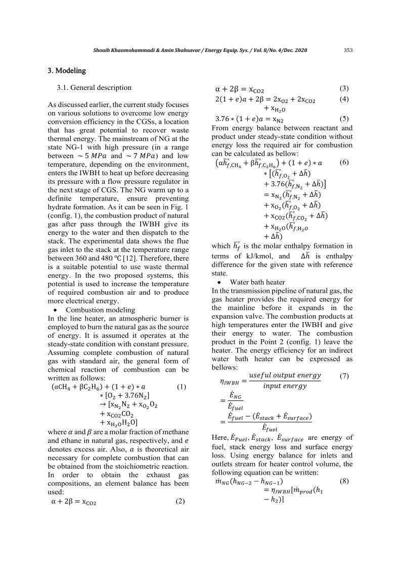
In the first configuration, which is the basic design for a water bath heater, after heat transfer with a water bath in the heater, the combustion products leave the heater in
relatively high temperature between 360 ℃ and 480 ℃. As it can be seen from Fig. 7, the stack loss and required heat for the natural gas mainline with increased ambient temperature shows an increment. In addition, the result for 𝐶𝑂2 emission reveals that for the change the natural gas flow rate through a year, the 𝐶𝑂2 emission of the station can change between 45.69 kg/h and 240.8 kg/h.
Figure 8 represents the fuel consumption of the station for average monthly temperature in different months of year. As the results show, the fuel mass flow rate in August has the minimum value, which directly goes back to the ambient temperature and natural gas mainline inlet temperature. (See Fig. 6 for variation of ambient and natural gas temperature).
Table 1. Ilam city gate station characteristics.
Capacity Dry gas filter Regulator valve Water bath heater
Siz
e
Wo
rkin
g
clas
s
No
. fi
lter
s
Siz
e
Wo
rkin
g
clas
s
No
. fi
lter
s
Wo
rkin
g
pre
ssu
re
Bat
h w
ater
cap
acit
y
No
. o
f co
il
Ilam CGS 100000
(SCM/h)
8
(inch) 600 3
4
(inch) 600 6 1050 (pisg)
38000
(lit) 7
Fig. 6. Temperature variation of inlet natural gas to Ilam CGS in 2015.
0
5
10
15
20
25
30
35
Jan Feb Mar Apr May Jun Jul Aug Sep Oct Nov Dec
Tem
per
ature
(˚C
)
Ambient temperature Natural gas temperature inlet heater
358 Shoaib Khanmohammadi & Amin Shahsavar / Energy Equip. Sys. / Vol. 8/No. 4/Dec. 2020
Fig. 7. Thermal and emission characteristics of IWBH in the first configuration.
Fig. 8. Fuel combustion for Ilam CGS for different month and average high, low and mean temperature.
One of the substantial parameter, which controls the flame temperature and gas product temperature, is excess air. Figure 9 shows the change of two main outputs with combustion excess air change. As it can be seen, an increment in the excess air leads to a decrement in flame temperature. In addition, the results show that with increment of the excess air from 50% to 150% the stack loss
increase from 115.2 kW to 232.1 kW. One of the main reasons to increase stack loss is an increment of combustion product mass flow rate. More analysis reveals that excess air increment in the range of 50% to 150% leads to an increase in the mass flow rate of combustion products from 0.236 kg/s to 0.49 kg/s, which substantially affect the stack heat loss.
0
50
100
150
200
250
300
0
100
200
300
400
500
600
Jan Feb Mar Apr May Jun Jul Aug Sep Oct Nov Dec
Carb
on d
ioxid
e emissio
n (k
g/h
)
Sta
ck l
oss
and
nat
ura
l gas
hea
t (k
W)
Stack loss Q_NG(kW) CO2
0.000
0.004
0.008
0.012
0.016
Jan Feb Mar Apr May Jun Jul Aug Sep Oct Nov Dec
Fuel
flo
w r
ate
(kg/s
)

Shoaib Khanmohammadi & Amin Shahsavar / Energy Equip. Sys. / Vol. 8/No. 4/Dec. 2020 359
Fig. 9. Flame temperature and stack loss variation with the change of excess air.
The excess air also affects the system efficiency and emission characteristics of the system. As Fig. 10 shows at the temperature ambient of 17.5 ℃ and natural gas pressure inlet to the station of 5.442 Mpa, increase the excess air from 50% to 150% leads to decrease the efficiency of heater from 57.2% to 46.4%. In addition, the 𝐶𝑂2 emission of the
system with the excess air changes can increase from 87 kg/h to 111 kg/h.
It can conclude that the lower excess air leads to decrease in heater efficiency while increases the stack loss and emissions. The stack decrement trend with increase excess air is more important when the exhaust combustion of gas product utilizes to derive ORC in configuration III.
Fig. 10. Variation of heater efficiency and 𝐶𝑂2 emission with the change of excess air.
100
120
140
160
180
200
220
240
260
280
900
1000
1100
1200
1300
1400
1500
1600
1700
1800
40 60 80 100 120 140 160
Stack
loss (k
W)
Fla
me
tem
per
ature
(˚C
)
Excess air (%)
𝑇𝑎𝑚𝑏 = 17.5 ℃ (Annual average)
Natural gas inlet pressure inlet to station=54.42 bar
Stack inlet temperature=450 ℃
85
90
95
100
105
110
115
120
125
46
48
50
52
54
56
58
60
62
64
40 60 80 100 120 140 160
CO
2 em
ission (k
g/h
) Hea
t ef
fici
ency
(%
)
Excess air (%)
𝑇𝑎𝑚𝑏 = 17.5 ℃ Annual averageNatural gas pressure inlet to station=54.42 bar
Stack inlet temperature=450 ℃
360 Shoaib Khanmohammadi & Amin Shahsavar / Energy Equip. Sys. / Vol. 8/No. 4/Dec. 2020
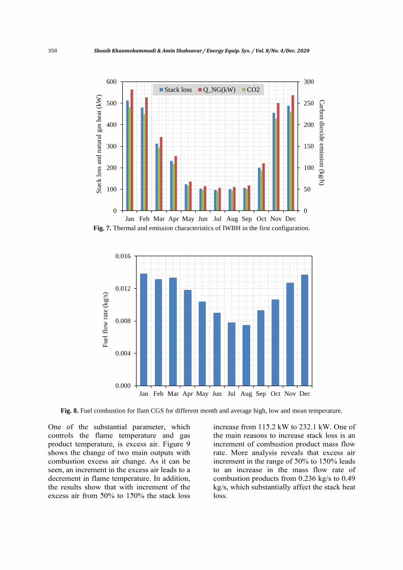
4.2. Configuration II
The stack loss is a significant parameter, which its effects are more considerable in cold weather. In the second configuration, the potential of stack waste heat to warm up the required combustion air is investigated. For annual average maximum, annual average minimum and annual average temperature, the variation of system efficiency is presented in Fig. 11.
As the results indicate in the second configuration, with increase excess air a decrement in the system efficiency takes place. It can be seen that for excess air increment from 50% to 200%, the stack losses increase from 4.534 kW to 4.668 kW and fuel mass flow rate from 20.99 kg/h to 21.65 kg/h. Moreover, it can be found that at higher
ambient temperature, the thermal efficiency of the system is higher.
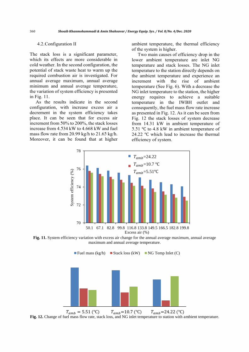
Two main causes of efficiency drop in the lower ambient temperature are inlet NG temperature and stack losses. The NG inlet temperature to the station directly depends on the ambient temperature and experience an increment with the rise of ambient temperature (See Fig. 6). With a decrease the NG inlet temperature to the station, the higher energy requires to achieve a suitable temperature in the IWBH outlet and consequently, the fuel mass flow rate increase as presented in Fig. 12. As it can be seen from Fig. 12 the stack losses of system decrease from 14.31 kW in ambient temperature of 5.51 ℃ to 4.8 kW in ambient temperature of 24.22 ℃ which lead to increase the thermal efficiency of system.
Fig. 11. System efficiency variation with excess air change for the annual average maximum, annual average
maximum and annual average temperature.
Fig. 12. Change of fuel mass flow rate, stack loss, and NG inlet temperature to station with ambient temperature.
70
72
74
76
78
50.1 67.1 82.8 99.8 116.8 133.8 149.5 166.5 182.8 199.8
Syst
em e
ffic
iency
(%
)
Excess air (%)
ambient temperature=24.22
°Cambient temperature=10.7 °C
𝑇𝑎𝑚𝑏=24.22
𝑇𝑎𝑚𝑏=10.7 ℃
𝑇𝑎𝑚𝑏=5.51℃
Tamb=5.51 (C) Tamb=10.7 (C) Tamb=24.22 (C)
Fuel mass (kg/h) Stack loss (kW) NG Temp Inlet (C)
𝑇𝑎𝑚𝑏 = 5.51 (℃) 𝑇𝑎𝑚𝑏=10.7 (℃) 𝑇𝑎𝑚𝑏=24.22 (℃)

Shoaib Khanmohammadi & Amin Shahsavar / Energy Equip. Sys. / Vol. 8/No. 4/Dec. 2020 361
4.3. Configuration III
In the third configuration, an ORC is employed to recover the waste heat energy of the water bath heater in CGS. Working fluid selection is so important for ORC performance and severely affect the efficiency and output of the system. The exhaust temperature and outlet stream enthalpy of gas products are two important values in working fluid selection. In this study it assumed that the ORC operates with a maximum pressure of 1000 kPa and condensation temperature of 40 ℃.
Figure 13 illustrates a schematic of T-S diagram for four selected working fluids. Because a wet fluid like water has a large latent heat of evaporation properties were not included here.
Also, the combustion product's exhaust temperature, which feed the ORC evaporator, is 450 ℃. The source temperature and working fluid pressure are two main criteria
in selecting a fluid for ORC system. Using these two facts, Table 2 represents the main properties of selected working fluids.
The higher critical temperature and pressure of working fluid is an advantage in selecting a working agent. However, here the net produced output work and ORC efficiency are employed to determine the best working fluid among different options. As it has been shown in Table 2, the net produced work and ORC efficiency for Toluene as the working fluid are 56.56 kW and 22.65%, respectively, which is higher than other fluids. Moreover, the high critical values of pressure and temperature is another benefit to select Toluene as a working medium in this study.
Figure 14 represents the net produced work of ORC. At the higher ambient temperature, the produced work by ORC decreases due to the stack loss, as it has been shown.
Fig. 13. Schematic of T-S diagram for selected organic working fluids.
Table 2. Properties of selected organic working fluids [19-23].
Fluid type Molecular weight
(kg/kmol)
Boiling point
(℃)
Viscosity
(mPa.s)
𝑷𝒄
(𝒃𝒂𝒓)
𝑻𝒄
(℃)
�̇�𝑶𝑹𝑪
𝒌𝑾
𝜼𝑰,𝑶𝑹𝑪
(%)
Benzene 78.11 80.08 0.604 @ 25 ℃ 48.8 298 51.01 20.42
Toluene 92.14 110.6 0.56 @ 25 ℃ 41.3 319 56.56 22.65
Butene 56.11 -6.47 0.186 @ 25 ℃ 37.9 152 16.61 6.64
Ethanol 46.07 78.29 1.074 @ 20 ℃ 40.6 241 46.12 18.47
-100
0
100
200
300
400
-1 0 1 2 3 4 5
Tem
per
ature
(°C
)
Entropy (kJ/kgK)
Toluene
Benzene
Butene
Ethanol

362 Shoaib Khanmohammadi & Amin Shahsavar / Energy Equip. Sys. / Vol. 8/No. 4/Dec. 2020
Fig. 14. ORC net produced work in different ambient temperature.
In the third configuration, also the effects of excess air variation on the system performance investigated. As illustrated in Fig. 15, increase excess air leads to an increase both ORC net produced work and stack loss while decreasing the heater efficiency. However, increase excess air has a positive effect on the ORC output, it increases the stack loss and fuel mass flow rate that lead to a decrease the system efficiency. Results exhibit that with increase excess air from 50% to 200% the fuel mass flow rate increase from 35.97 kg/h to 52.95 kg/h.
4.4. Comparison of configurations
Figure 16 compares three configurations from system efficiency and stack heat loss point of view. As it expected, the first configuration, due to large part of stack heat loss (267.9 kW) has the lowest efficiency. In the second and third configuration, the thermal efficiency of the system due to recover waste heat energy increase to a reasonable value.
Fig. 15. Heater efficiency ORC output and stack loss with excess air variation.
0
10
20
30
40
50
60
70
Tamb=5.51 Tamb=10.7 Tamb=24.22
OR
C p
ow
er o
utp
ut
(kW
)
0
20
40
60
80
100
50
54
58
62
66
40 90 140 190 240
OR
C w
ork
outp
ut an
d stack
loss (k
w)
Hea
ter
effi
ciec
y (
%)
Excess air (%)
Heater efficiency
Stack loss
ORC Work

Shoaib Khanmohammadi & Amin Shahsavar / Energy Equip. Sys. / Vol. 8/No. 4/Dec. 2020 363
Fig. 16. Variation of system efficiency and stack loss for different configurations of
indirect water bath heater from.
In the second configuration, a large part of waste heat from the stack is used to heat up required air to combustion. Hence the fuel mass flow rate severely shows a decrement. As it can be seen in Fig. 17 the 𝐶𝑂2 emission also mitigate with preheating the combustion air effectively.
Although the emission per hour for the first configuration (base case) and third configuration has the same value, it should be noticed that in the third configuration, beside the NG heating with a fixed fuel mass flow rate, some work generated via ORC that indicate the comparative advantage of the third system.
Fig. 17. Fuel mass flow rate and emission of 𝐶𝑂2 for different configurations.
46.36
267.9
73.84
11.4
55.27
18.16
System eff.(%) Stack loss (kW)
Config. 1
Config. 2
Config. 3
45.72
125.8
28.71
78.97
45.72
125.8
Fuel mass flow rate (kg/h) CO2 Emission (kg/h)
Config. 1
Config. 2
Config. 3

364 Shoaib Khanmohammadi & Amin Shahsavar / Energy Equip. Sys. / Vol. 8/No. 4/Dec. 2020
5. Conclusion
In this work, real data of selected city gate stations has been analyzed and a station selected for more investigations. Three system configurations have been studied to find the best arrangement of an in-use CGS. The suggested systems have been utilized to assess revision, such as preheating the air combustion and stack loss energy recovery to produce electrical energy. The results indicated that for the first configuration (base case), second configuration (preheating air combustion), and a third configuration (ORC to recover stack loss), energy efficiency is 46.36%, 73.84% and 55.27%, respectively. Through the results analyses process, it conceives that for the base case, a large part of energy waste in the stack that severely reduce the thermal efficiency of system. Numerical calculation shows the waste thermal energy for base configuration is 267.9 kW. Therefore, the second and third arrangements are proposed based on this suitable potential to recover waste energy. Excess air is one of the main parameters, which control the flame temperature and substantially affect the system performance. It concluded that with the increase the excess air, the stack loss for three configurations has been increased. The results of carbon dioxide emission represent that the second configuration with 78.97 kg/h has the lowest emission, which mainly due to preheating the combustion air. In the third configuration, the working fluid selection procedure reveals that Toluene is the best working fluid medium based on work output and thermal efficiency of ORC. The analysis also shows that with the use of ORC to recover waste heat energy, in 200% excess air, 79 kW of electrical energy can be generated. Thermodynamic analysis of on the new proposed configurations and traditional configuration confirm the new proposed systems to utilize are more efficient. Acknowledgment The authors would like to acknowledge the National Iranian Gas Company (NIGC) for helpful support.
References [1] Arabkoohsar, A., L. Machado, and R.
Koury, Operation analysis of a photovoltaic plant integrated with a compressed air energy storage system and a city gate station. Energy, 2016. 98: 78-91.
[2] Farzaneh-Gord, M., S., Hashemi, and M. Sadi, Energy destruction in Iran's natural gas pipe line network. Energy Exploration & Exploitation, 2007. 25: 393-406.
[3] Sanaye, S. and A. Mohammadi Nasab, Modeling and optimizing a CHP system for natural gas pressure reduction plant. Energy, 2012. 40: 358-369.
[4] Neseli, M.A., O. Ozgener, L. Ozgener, Energy and exergy analysis of electricity generation from natural gas pressure reducing stations. Energy Conversion and Management, 2015. 93: 109-120.
[5] Arabkoohsar, A., M. Farzaneh-Gord, M. Deymi-Dashtebayaz, L. Machado, R.N.N. Koury, A new design for natural gas pressure reduction points by employing a turbo expander and a solar heating set, Renewable Energy, 2015. 81: 239-250.
[6] Tan, H., Q. Zhao, N. Sun, and Y. Li, Proposal and design of a natural gas liquefaction process recovering the energy obtained from the pressure reducing stations of high-pressure pipelines. Cryogenics, 2016. 80: 82-90.
[7] Farzaneh-Gord, M., A. Arabkoohsar, M. Rezaei, M.D. Dasht-bayaz, and H.R. Rahbari, Feasibility of employing solar energy in natural gas pressure drop stations. Journal of the Energy Institute, 2011. 84: 165-173.
[8] Ashouri, E., et al., The minimum gas temperature at the inlet of regulators in natural gas pressure reduction stations (CGS) for energy saving in water bath heaters. Journal of Natural Gas Science and Engineering, 2014. 21: 230-240.
[9] Zabihi, A. and M. Taghizadeh, New energy-saving temperature controller for heater at natural gas gate station. Journal of Natural Gas Science and Engineering, 2015. 27: 1043-1049.

Shoaib Khanmohammadi & Amin Shahsavar / Energy Equip. Sys. / Vol. 8/No. 4/Dec. 2020 365
[10] Ghezelbash, R., M. Farzaneh-Gord, and M. Sadi, Performance assessment of vortex tube and vertical ground heat exchanger in reducing fuel consumption of conventional pressure drop stations. Applied Thermal Engineering, 2016. 102: 213-226.
[11] Farzaneh-Gord, M., R. Ghezelbash, M. Sadi, and A. Jabari Moghadam, Integration of vertical ground-coupled heat pump into a conventional natural gas pressure drop station: Energy, economic and CO2 emission assessment. Energy, 2016. 112: 998-1014.
[12] Khalili, E., S.M. Hosseinalipour, and E. Hybatian. Efficiency and heat losses of indirect water bath heater installed in natural gas pressure reduction station; evaluating a case study in Iran. In 8th International Energy Conference. 2011. Tehran.
[13] Incropera, F. P. and D. P. De Witt, Fundamentals of heat and mass transfer, 1985.
[14] Khanmohammadi, S., P. Heidarnejad, N. Javani and H. Ganjehsarabi, Exergoeconomic analysis and multi objective optimization of a solar based integrated energy system for hydrogen production." International Journal of Hydrogen Energy, 2017, in press.
[15] Farzaneh-Kord, V., A. Khoshnevis, A. Arabkoohsar, M. Deymi-Dashtebayaz, M. Aghili, M. Khatib, M. Kargaran and M. Farzaneh-Gord, Defining a technical criterion for economic justification of employing CHP technology in city gate stations. Energy 2016. 111: 389-401.
[16] Khanmohammadi, S., P. Ahmadi, K. Atashkari and R. K. Kamali (2015). Design and Optimization of an Integrated System to Recover Energy from a Gas Pressure Reduction Station. Progress in Clean Energy 2015. 1: 89-107.
[17] Iran meteorological organization website: www.irimo.ir
[18] Iranian ministry of petroleum, website: www.mop.ir/
[19] Bao, J. and L. Zhao, A review of working fluid and expander selections for organic Rankine cycle. Renewable and Sustainable Energy Reviews 2013. 24: 325-342.
[20] Tchanche, B. F., G. Papadakis, G. Lambrinos and A. Frangoudakis, Fluid selection for a low-temperature solar organic Rankine cycle. Applied Thermal Engineering 2009. 29: 2468-2476.
[21] Sprouse, C., and C. Depcik, Review of organic Rankine cycles for internal combustion engine exhaust waste heat recovery. Applied thermal engineering 2013. 51: 711-722.
[22] Khanmohammadi, S., Saadat-Targhi M., Thermodynamic modeling and analysis of a novel heat recovery system in a natural gas city gate station, Journal of Cleaner Production , 2019, 224: 346-360
[23] M Saadat-Targhi, S Khanmohammadi, Energy and exergy analysis and multi-criteria optimization of an integrated city gate station with organic Rankine flash cycle and thermoelectric generator, Applied Thermal Engineering, 2019, 149, 312-324