thermocouple/mv manual analog input module · plc, plc-2, plc-3, and plc-5 are ... this manual...
TRANSCRIPT

UserManual
SLC 500™ Thermocouple/mV Analog Input Module
(Catalog Number 1746-NT8)
Allen-Bradley

Important User Information Because of the variety of uses for the products described in this publication, those responsible for the application and use of this control equipment must satisfy themselves that all necessary steps have been taken to assure that each application and use meets all performance and safety requirements, including any applicable laws, regulations, codes and standards.
The illustrations, charts, sample programs and layout examples shown in this guide are intended solely for purposes of example. Since there are many variables and requirements associated with any particular installation, Allen-Bradley does not assume responsibility or liability (to include intellectual property liability) for actual use based upon the examples shown in this publication.
Allen-Bradley publication SGI-1.1, Safety Guidelines for the Application, Installation and Maintenance of Solid-State Control (available from your local Allen-Bradley office), describes some important differences between solid-state equipment and electromechanical devices that should be taken into consideration when applying products such as those described in this publication.
Reproduction of the contents of this copyrighted publication, in whole or part, without written permission of Rockwell Automation, is prohibited.
Throughout this manual we use notes to make you aware of safety considerations:
Attention statements help you to:
• identify a hazard
• avoid a hazard
• recognize the consequences
Important: Identifies information that is critical for successful application and understanding of the product.
PLC, PLC-2, PLC-3, and PLC-5 are registered trademarks of Rockwell Automation. SLC, SLC 500, SLC 5/01, SLC 5/02, SLC 5/03, SLC 5/04, and SLC 5/05 are registered trademarks of Rockwell Automation. Belden is a trademark of Belden, Inc.
!ATTENTION: Identifies information about practices or circumstances that can lead to personal injury or death, property damage or economic loss

Table of Contents
PrefaceWho Should Use This Manual . . . . . . . . . . . . . . . . . . . . . . . . . P-1What This Manual Covers . . . . . . . . . . . . . . . . . . . . . . . . . . . . P-1Related Allen-Bradley Documents . . . . . . . . . . . . . . . . . . . . . . P-2Common Techniques Used in this Manual . . . . . . . . . . . . . . . . P-3Allen-Bradley Support . . . . . . . . . . . . . . . . . . . . . . . . . . . . . . . P-3
Local Product Support . . . . . . . . . . . . . . . . . . . . . . . . . . . . . P-3Technical Product Assistance . . . . . . . . . . . . . . . . . . . . . . . P-3Your Questions or Comments on this Manual . . . . . . . . . . . P-3
Module Overview Chapter 1General Description . . . . . . . . . . . . . . . . . . . . . . . . . . . . . . . . . 1-1
Input Ranges . . . . . . . . . . . . . . . . . . . . . . . . . . . . . . . . . . . . 1-1Hardware Features . . . . . . . . . . . . . . . . . . . . . . . . . . . . . . . 1-2Diagnostic LEDs . . . . . . . . . . . . . . . . . . . . . . . . . . . . . . . . . 1-3
System Overview . . . . . . . . . . . . . . . . . . . . . . . . . . . . . . . . . . . 1-3System Operation . . . . . . . . . . . . . . . . . . . . . . . . . . . . . . . . 1-3Module Operation . . . . . . . . . . . . . . . . . . . . . . . . . . . . . . . . 1-4Module Addressing . . . . . . . . . . . . . . . . . . . . . . . . . . . . . . . 1-4Block Diagram . . . . . . . . . . . . . . . . . . . . . . . . . . . . . . . . . . . 1-5Linear Millivolt Device Compatibility. . . . . . . . . . . . . . . . . . . 1-6
Installing And WiringYour Module Chapter 2
Electrostatic Damage . . . . . . . . . . . . . . . . . . . . . . . . . . . . . . . . 2-1Power Requirements . . . . . . . . . . . . . . . . . . . . . . . . . . . . . . . . 2-2
Considerations for a Modular System. . . . . . . . . . . . . . . 2-2Fixed I/O Chassis - I/O Module Compatibility . . . . . . . . . 2-3
General Considerations . . . . . . . . . . . . . . . . . . . . . . . . . . . . . . 2-4Module Installation and Removal . . . . . . . . . . . . . . . . . . . . . . . 2-5
Terminal Block Removal . . . . . . . . . . . . . . . . . . . . . . . . . 2-6Wiring Your Module . . . . . . . . . . . . . . . . . . . . . . . . . . . . . . . . . 2-7
Preparing and Wiring the Cables . . . . . . . . . . . . . . . . . . 2-8Cold-Junction Compensation (CJC). . . . . . . . . . . . . . . . . . 2-10
Publication 1746-6.22

ii Table of Contents
Things To ConsiderBefore UsingYour Module Chapter 3
Module ID Code . . . . . . . . . . . . . . . . . . . . . . . . . . . . . . . . . 3-1Module Addressing . . . . . . . . . . . . . . . . . . . . . . . . . . . . . . . 3-2
Output Image - Configuration Words . . . . . . . . . . . . . . . 3-2Input Image - Data Words and Status
Words. . . . . . . . . . . . . . . . . . . . . . . . . . . . . . . . . . . . . 3-3Channel Filter Frequency Selection . . . . . . . . . . . . . . . . . . 3-3
Channel Cut-Off Frequency . . . . . . . . . . . . . . . . . . . . . . 3-4Channel Step Response . . . . . . . . . . . . . . . . . . . . . . . . 3-6
Update Time . . . . . . . . . . . . . . . . . . . . . . . . . . . . . . . . . . . . 3-7Update Time Calculation Example. . . . . . . . . . . . . . . . . 3-7
Channel Turn-On, Turn-Off, and ReconfigurationTimes . . . . . . . . . . . . . . . . . . . . . . . . . . . . . . . . . . . . . . . . . 3-8Auto-Calibration . . . . . . . . . . . . . . . . . . . . . . . . . . . . . . . . . 3-8Response to Slot Disabling . . . . . . . . . . . . . . . . . . . . . . . . 3-9
Input Response . . . . . . . . . . . . . . . . . . . . . . . . . . . . . . . 3-9Output Response . . . . . . . . . . . . . . . . . . . . . . . . . . . . . . 3-9
Channel Configuration,Data, and Status Chapter 4
Channel Configuration . . . . . . . . . . . . . . . . . . . . . . . . . . . . 4-1Channel Configuration Procedure . . . . . . . . . . . . . . . . . . . 4-2
Select Channel Enable (Bit 0) . . . . . . . . . . . . . . . . . . . . 4-5Select Input Types (Bits 1 through 4). . . . . . . . . . . . . . . 4-5Select Data Format (Bits 5 and 6) . . . . . . . . . . . . . . . . . 4-5Using Scaled-for-PID and
Proportional Counts . . . . . . . . . . . . . . . . . . . . . . . . . . 4-6Effective Resolutions . . . . . . . . . . . . . . . . . . . . . . . . 4-6Scaling Examples . . . . . . . . . . . . . . . . . . . . . . . . . . . 4-7
Select Open-Circuit State (Bits 7 and 8) . . . . . . . . . . . . 4-9Select Temperature Units (Bit 9) . . . . . . . . . . . . . . . . . 4-10Select Channel Filter Frequency
(Bits 10 and 11) . . . . . . . . . . . . . . . . . . . . . . . . . . . . 4-10Unused Bits (Bits 12 through 14) . . . . . . . . . . . . . . 4-11Select Input Image Type (Bit 15) . . . . . . . . . . . . . . 4-11
Channel Data/Status Word . . . . . . . . . . . . . . . . . . . . . . . . 4-12Channel Status Checking . . . . . . . . . . . . . . . . . . . . . . . . . 4-12
Channel Status (Bit 0). . . . . . . . . . . . . . . . . . . . . . . 4-14Input Type Status (Bits 1 through 4) . . . . . . . . . . . . 4-14Data Format Type Status (Bits 5 and 6) . . . . . . . . . 4-14Open-Circuit Type Status (Bits 7 and 8) . . . . . . . . . 4-14Temperature Units Type Status (Bit 9) . . . . . . . . . . 4-14
Publication 1746-6.22
Table of Contents iii
Channel Filter Frequency(Bits 10 and 11) . . . . . . . . . . . . . . . . . . . . . . . . . 4-14
Open-Circuit Error (Bit 12) . . . . . . . . . . . . . . . . . . . 4-14Under-Range Error (Bit 13) . . . . . . . . . . . . . . . . . . 4-15Over-Range Error (Bit 14) . . . . . . . . . . . . . . . . . . . 4-15Channel Error (Bit 15) . . . . . . . . . . . . . . . . . . . . . . 4-15
Programming Examples Chapter 5Basic Example . . . . . . . . . . . . . . . . . . . . . . . . . . . . . . . . . . 5-1
Procedure . . . . . . . . . . . . . . . . . . . . . . . . . . . . . . . . . . . 5-2Automatic Monitoring Thermocouplesand CJC Sensors . . . . . . . . . . . . . . . . . . . . . . . . . . . . . . . . 5-3Verifying Channel Configuration Changes . . . . . . . . . . . . . 5-3Interfacing to the PID Instruction . . . . . . . . . . . . . . . . . . . . 5-7Monitoring Channel Status Bits . . . . . . . . . . . . . . . . . . . . . 5-8PLC 5 Example with NT8 in Remote I/O Rack . . . . . . . . 5-14
TroubleshootingYour Module Chapter 6
Module and Channel Diagnostics . . . . . . . . . . . . . . . . . . . 6-1Module Diagnostics at Powerup . . . . . . . . . . . . . . . . . . 6-1Channel Diagnostics . . . . . . . . . . . . . . . . . . . . . . . . . . . 6-1
LED Indicators . . . . . . . . . . . . . . . . . . . . . . . . . . . . . . . . . . 6-2LED Troubleshooting Tables. . . . . . . . . . . . . . . . . . . . . 6-2Channel-status LEDs (Green) . . . . . . . . . . . . . . . . . . . . 6-3Open-circuit Detection (Bit 12) . . . . . . . . . . . . . . . . . . . 6-3Out-of-Range Detection (Bit 13 for Under Range,
bit 14 for Over Range) . . . . . . . . . . . . . . . . . . . . . . . 6-3Channel Error (Bit 15) . . . . . . . . . . . . . . . . . . . . . . . . . . 6-4Module Status LED (Green) . . . . . . . . . . . . . . . . . . . . . 6-4
Interpreting I/O Error Codes . . . . . . . . . . . . . . . . . . . . . . . 6-4
Maintaining YourModule And SafetyConsiderations Chapter 7
Preventive Maintenance . . . . . . . . . . . . . . . . . . . . . . . . . . 7-1Safety Considerations . . . . . . . . . . . . . . . . . . . . . . . . . . . . 7-1
Publication 1746-6.22
iv Table of Contents
Module Specifications Appendix AElectrical Specifications . . . . . . . . . . . . . . . . . . . . . . . . . . .A-1Physical Specifications . . . . . . . . . . . . . . . . . . . . . . . . . . . .A-1Environmental Specifications . . . . . . . . . . . . . . . . . . . . . . .A-2Input Specifications . . . . . . . . . . . . . . . . . . . . . . . . . . . . . .A-2
Overall Accuracy . . . . . . . . . . . . . . . . . . . . . . . . . . . . . .A-2Millivolt . . . . . . . . . . . . . . . . . . . . . . . . . . . . . . . . . . . . . .A-3Thermocouple . . . . . . . . . . . . . . . . . . . . . . . . . . . . . . . .A-5
Using Grounded Junction,Ungrounded Junction,and Exposed JunctionThermocouples Appendix B
Thermocouple Types . . . . . . . . . . . . . . . . . . . . . . . . . . . . .B-1Grounded Junction . . . . . . . . . . . . . . . . . . . . . . . . . .B-2Ungrounded (Insulated) Junction . . . . . . . . . . . . . . .B-2Exposed Junction . . . . . . . . . . . . . . . . . . . . . . . . . . .B-2
Isolation . . . . . . . . . . . . . . . . . . . . . . . . . . . . . . . . . . . . . . .B-2Grounded Junction Thermocouples. . . . . . . . . . . . . . . .B-3Exposed Junction Thermocouples . . . . . . . . . . . . . . . . .B-4
Glossary
Index
Publication 1746-6.22

trol
at
Preface
Read this preface to familiarize yourself with this user manual. This preface covers:
• who should use this manual
• what this manual provides
• related Allen-Bradley documents
• common techniques used in this manual
• Allen-Bradley support
Who Should Use This Manual
Use this manual if you design, install, program, or maintain a consystem that uses Allen-Bradley Small Logic Controllers (SLC).
You should have a basic understanding of SLC 500 products. Youshould also understand electronic process control and the ladder program instructions required to generate the electronic signals thcontrol your application. If you do not, contact your local Allen-Bradley representative for the proper training before using these products.
What This Manual Covers
This manual covers the 1746-NT8 thermocouple/millivolt analog input module. It contains the information you need to install, wire,use, and maintain these modules. It also provides diagnostic andtroubleshooting help should the need arise.
Publication 1746-6.22

P-2 Preface
Related Allen-Bradley Documents
The following table lists several Allen-Bradley documents that may help you as you use these products.
To obtain a copy of any of the Allen-Bradley documents listed, contact your local Allen-Bradley office or distributor.
Publication Number Title
1747-2.30 SLC 500 System Overview
SGI-1.1 Application Considerations for Solid State Controls
1770-4.1 Allen-Bradley Programmable Controller Grounding and Wiring Guidelines
1747-6.2 Installation & Operation Manual for Modular Hardware Style Programmable Controllers
1747-6.21 Installation & Operation Manual for Fixed Hardware Style Programmable Controllers
1747-6.15 SLC 500 Instruction Set Reference Manual
ABT-1747-TSG001 SLC 500 Software Programmers’s Quick Reference Guide
1747-NP002 Allen-Bradley HHT (Hand-Held Terminal) User Manual
1747-NM009 Getting Started Guide for HHT (Hand-Held Terminal)
SD499 Allen-Bradley Publication Index
AG-7.1 Allen-Bradley Industrial Automation Glossary
Publication 1746-6.22

Preface P-3
e.
s/
plus
se
ore
Common Techniques Used in this Manual
The following conventions are used throughout this manual:
• Bulleted lists such as this one provide information, not procedural steps.
• Numbered lists provide sequential steps or hierarchical information.
• Text in this font indicates words or phrases you should typ
• Key names appear in bold, capital letters within brackets (forexample, [ENTER]).
Allen-Bradley Support Allen-Bradley offers support services worldwide, with over 75 SaleSupport Offices, 512 authorized Distributors and 260 authorized Systems Integrators located throughout the United States alone, Allen-Bradley representatives in every major country in the world.
Local Product Support
Contact your local Allen-Bradley representative for:
• sales and order support
• product technical training
• warranty support
• support service agreements
Technical Product Assistance
If you need to contact Allen-Bradley for technical assistance, pleareview the information in the Troubleshooting chapter first. Then call your local Allen-Bradley representative.
Your Questions or Comments on this Manual
If you find a problem with this manual, please notify us of it on theenclosed Publication Problem Report.
If you have any suggestions for how this manual could be made museful to you, please contact us at the address below:
Allen-Bradley
Control and Information Group
Technical Communication, Dept. A602V, T122
P.O. Box 2086
Milwaukee, WI 53201–2086
Publication 1746-6.22

for e
at
Chapter 1
Module Overview
This chapter describes the thermocouple/mv input module and explains how the SLC 500 processor reads thermocouple or millivolt analog input data from the module.
Read this chapter to familiarize yourself further with your thermocouple/mV analog input module. This chapter covers:
• general description and hardware features
• an overview of system and module operation
• block diagram of channel input circuits
General Description This module is designed exclusively to mount into 1746 I/O racks use with SLC 500 fixed and modular systems. The module storesdigitally converted thermocouple/mV analog data in its image tablfor retrieval by all fixed and modular SLC 500 processors. The module supports connections from any combination of up to eightthermocouple/mV analog sensors.
Input Ranges
The following tables define thermocouple types and associated temperature ranges and the millivolt analog input signal ranges theach of the module’s input channels support. To determine the practical temperature range of your thermocouple, refer to the specifications in appendix A.
Thermocouple Temperature Ranges
Millivolt Input Ranges
Type °C Temperature Range °F Temperature Range
J -210°C to +760°C -346°F to +1400°F
K -270°C to +1370°C -454°F to +2498°F
T -270°C to +400°C -454°F to +752°F
B +300°C to +1820°C +572°C to +3308°F
E -270°C to +1000°C -454°F to +1832°F
R 0°C to +1768°C +32 F to +3214°F
S 0°C to +1768°C +32°F to +3214°F
N 0°C to +1300°C +32°F to +2372°F
CJC Sensor -25°C to +105°C -13°F to +221 °F
-50 to +50 mV
-100 to +100 mV
Publication 1746-6.22

1-2 Module Overview
Each input channel is individually configured for a specific input device, and provides open-circuit, over-range, and under-range detection and indication.
Hardware Features
The module fits into any single slot for I/O modules in either an SLC 500 modular system or an SLC 500 fixed system expansion chassis (1746-A2), except the zero slot which is reserved for the processor. It
is a Class 1 module using 8 input words and 8 output words.1
The module contains a removable terminal block providing connections for eight thermocouple and/or analog input devices. On the terminal block are two cold-junction compensation (CJC) sensors that compensate for the cold junction at ambient temperature. It should also be noted there are no output channels on the module. Configure the module with software rather than with jumpers or switches.
1. Requires use of a Block Transfer when used in a remote rack with a 1747-ASB.
Important: There is a jumper (JP1) on the circuit board. The module is shipped with the jumper in the up position as illustrated below. Do not change the position of JP1. The jumper is used for test purposes only.
SLC 500
CAT
SERIAL N
O.
THERMO
COUPLE/m
V INPUT MO
DULE
MAD
E IN U
SAFAC
1M
INPU
T SIGN
AL RAN
GES
THER
MO
CO
UPLE TYPES:
VOLTAG
E:
±100mVD
C to +100m
VDC
±50mVD
C to +50m
VDC
SER
FRN )
ULLISTED
IND
. CO
NT. EQ
.FO
R H
AZ. LOC
. A196C
LASS I, GR
OU
PS A, B, C AN
D D
, DIV.2
OPER
ATING
)
SAJ, K, T, E, R
, S, B, NTEM
PERATU
RE
CO
DE T3C
1746 NT4
NT4±xxx x
MODULE
01
45
21
23
CHANNELSTATUS
THERMOCOUPLE/mV
INPUT
CJC A+CJC A-CHL 0+CHL 0-SHIELDCHL 1+CHL 1-CHL 2+CHL 2-SHIELDCHL 3+CHL 3-CHL 4+CHL 4-SHIELDCHL 5+CHL 5-CHL 6+CHL 6-SHIELDCHL 7+CHL 7-CJC B+CJC B-
1746-NT8
JP1
Side Label
Self-Locking Tabs
Door Label
Channel Status LEDs (Green)
Module Status LED (Green)
Removable Terminal Block
CJC Sensors
Cable Tie Slots
Jumper - Do Not Move.
Publication 1746-6.22
Module Overview 1-3
Hardware Features
Diagnostic LEDs
The module contains diagnostic LEDs that help you identify the source of problems that may occur during power-up or during normal operation. Power-up and channel diagnostics are explained in Chapter 6, Testing Your Module.
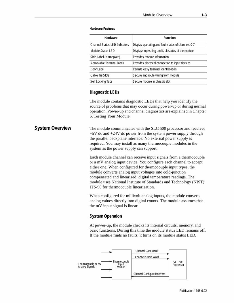
System Overview The module communicates with the SLC 500 processor and receives +5V dc and +24V dc power from the system power supply through the parallel backplane interface. No external power supply is required. You may install as many thermocouple modules in the system as the power supply can support.
Each module channel can receive input signals from a thermocouple or a mV analog input device. You configure each channel to accept either one. When configured for thermocouple input types, the module converts analog input voltages into cold-junction compensated and linearized, digital temperature readings. The module uses National Institute of Standards and Technology (NIST) ITS-90 for thermocouple linearization.
When configured for millivolt analog inputs, the module converts analog values directly into digital counts. The module assumes that the mV input signal is linear.
System Operation
At power-up, the module checks its internal circuits, memory, and basic functions. During this time the module status LED remains off. If the module finds no faults, it turns on its module status LED.
Hardware Function
Channel Status LED Indicators Display operating and fault status of channels 0-7
Module Status LED Displays operating and fault status of the module
Side Label (Nameplate) Provides module information
Removable Terminal Block Provides electrical connection to input devices
Door Label Permits easy terminal identification
Cable Tie Slots Secure and route wiring from module
Self Locking Tabs Secure module in chassis slot
SLC 500 Processor
Thermocouple Input
ModuleThermocouple or mV Analog Signals
Channel Data Word
Channel Status Word
Channel Configuration Word
Publication 1746-6.22
1-4 Module Overview
s
al
ut s
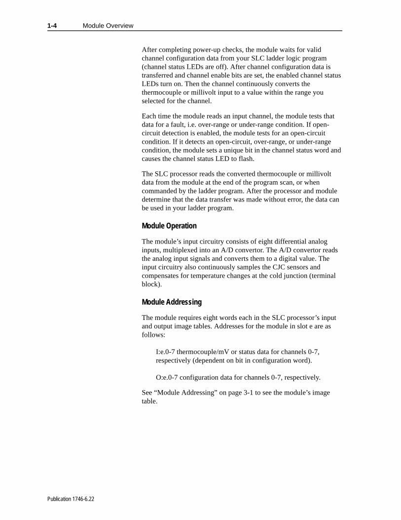
After completing power-up checks, the module waits for valid channel configuration data from your SLC ladder logic program (channel status LEDs are off). After channel configuration data is transferred and channel enable bits are set, the enabled channel status LEDs turn on. Then the channel continuously converts the thermocouple or millivolt input to a value within the range you selected for the channel.
Each time the module reads an input channel, the module tests that data for a fault, i.e. over-range or under-range condition. If open-circuit detection is enabled, the module tests for an open-circuit condition. If it detects an open-circuit, over-range, or under-range condition, the module sets a unique bit in the channel status word and causes the channel status LED to flash.
The SLC processor reads the converted thermocouple or millivolt data from the module at the end of the program scan, or when commanded by the ladder program. After the processor and module determine that the data transfer was made without error, the data can be used in your ladder program.
Module Operation
The module’s input circuitry consists of eight differential analog inputs, multiplexed into an A/D convertor. The A/D convertor readthe analog input signals and converts them to a digital value. Theinput circuitry also continuously samples the CJC sensors and compensates for temperature changes at the cold junction (terminblock).
Module Addressing
The module requires eight words each in the SLC processor’s inpand output image tables. Addresses for the module in slot e are afollows:
I:e.0-7 thermocouple/mV or status data for channels 0-7, respectively (dependent on bit in configuration word).
O:e.0-7 configuration data for channels 0-7, respectively.
See “Module Addressing” on page 3-1 to see the module’s imagetable.
Publication 1746-6.22
Module Overview 1-5
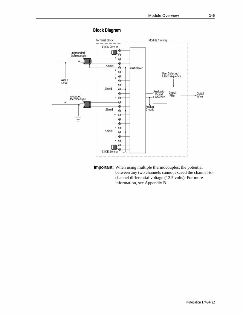
Block Diagram
+-
+-+-
+-
+-+-
+-
+-
+-
Terminal Block Module Circuitry
CJCA Sensor
Shield
Shield
Shield
Shield
CJCB Sensor
User Selected Filter Frequency
Digital Value
Analog to Digital
ConverterDigital Filter
multiplexer
Analog Ground
Within 12.5V
ungrounded thermocouple
grounded thermocouple
Important: When using multiple thermocouples, the potential between any two channels cannot exceed the channel-to-channel differential voltage (12.5 volts). For more information, see Appendix B.
Publication 1746-6.22

1-6 Module Overview
Linear Millivolt Device Compatibility
A large number of millivolt devices may be used with the 1746-NT8 module. For this reason we do not specify compatibility with any particular device.
However, millivolt applications often use strain gage bridges. A resistive voltage divider using fixed resistors is recommended for this application. The circuit diagram below shows how this connection is made.
+
-
+Strain Gage Bridge
1746-NT8
fixedfixed
variablefixed
Voc
Channel Input
Note: The resistors should be selected to ensure that the differential input voltage is less than or equal to ±100 mV.
Publication 1746-6.22

this
e
Chapter 2
Installing And Wiring Your Module
Read this chapter to install and wire your module. This chapter covers:
• avoiding electrostatic damage
• determining power requirements
• installing the module
• wiring signal cables to the module’s terminal block
Electrostatic Damage Electrostatic discharge can damage semiconductor devices insidemodule if you touch backplane connector pins. Guard against electrostatic damage by observing the following precautions:
!ATTENTION: Electrostatically Sensitive Components
• Before handling the module, touch a grounded object to rid yourself of electrostatic charge.
• Handle the module from the front, away from thebackplane connector. Do not touch backplane connector pins.
• Keep the module in its static-shield container when not in use or during shipment.
Failure to observe these precautions can degradthe module’s performance or cause permanent damage.
Publication 1746-6.22
2-2 Installing And Wiring Your Module
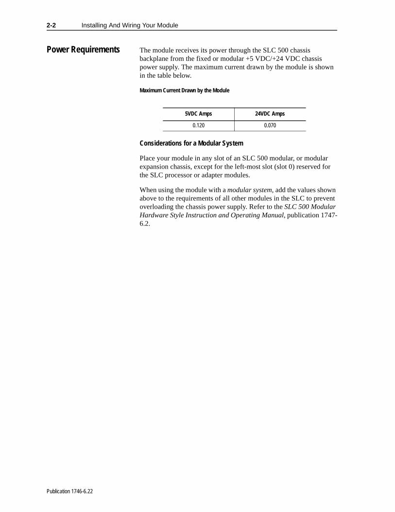
Power Requirements The module receives its power through the SLC 500 chassis backplane from the fixed or modular +5 VDC/+24 VDC chassis power supply. The maximum current drawn by the module is shown in the table below.
Maximum Current Drawn by the Module
Considerations for a Modular System
Place your module in any slot of an SLC 500 modular, or modular expansion chassis, except for the left-most slot (slot 0) reserved for the SLC processor or adapter modules.
When using the module with a modular system, add the values shown above to the requirements of all other modules in the SLC to prevent overloading the chassis power supply. Refer to the SLC 500 Modular Hardware Style Instruction and Operating Manual, publication 1747-6.2.
5VDC Amps 24VDC Amps
0.120 0.070
Publication 1746-6.22

Installing And Wiring Your Module 2-3
Fixed I/O Chassis - I/O Module Compatibility
The following chart depicts the range of current combinations supported by the fixed I/O expansion chassis. To use it, find the backplane current draw and operating voltage for both modules being used in the chassis. These specifications are found in the table alongside the chart.
Next, plot each of the currents on the chart below. If the point of intersection falls within the operating region, the combination is valid. If not, the combination cannot be used in a 2-slot, fixed I/O chassis.
Module Current Draw - Power Supply Loading
I/O Module 5V 24V I/O Module 5V 24V
BAS .150 .040 KE .150 .040
BASn .150 .125 KEn .150 .125
DCM .360 .000 NI4 .025 .085
FIO4I .055 .150 NI8 .200 .100
FIO4V .055 .120 NIO4I .055 .145
HS .300 .000 NIO4V .055 .115
HSTP1 .200 .000 NO4I .055 .195
IA4 .035 .000 NO4V .055 .145
IA8 .050 .000 NR4 .050 .050
IA16 .085 .000 NT4 .060 .040
IB8 .050 .000 OA16 .370 .000
IB16 .085 .000 OA8 .185 .000
IB32 .106 .000 OAP12 .370 .000
IC16 .085 .000 OB8 .135 .000
IG16 .140 .000 OB16 .280 .000
IH16 .085 .000 OB16E .135 .000
IM4 .035 .000 OB32 .452 .000
IM8 .050 .000 OBP8 .135 .000
IM16 .085 .000 OBP16 .250 .000
IN16 .085 .000 OG16 .180 .000
IO4 .030 .025 OV8 .135 .000
IO8 .060 .045 OV16 .270 .000
IO12 .090 .070 OV32 .452 .000
ITB16 .085 .000 OVP16 .250 .000
ITV16 .085 .000 OW16 .170 .180
IV8 .050 .000 OW4 .045 .045
IV16 .085 .000 OW8 .085 .090
IV32 .106 .000 OX8 .085 .090
Example: Plot IN16 and NIO4VIN16 = 0.085 at 5V dc and 0A at 24V dcNIO4V = 0.055A at 5V dc and 0.115A at 24V dc1. Add current draws of both modules at 5V dc to get 0.14
(140mA)2. Plot this point on the chart above (140mA at 5V dc).3. Add current draws of both modules at 24V dc to get
0.115A (115mA)4. Plot current draw at 24V dc (115mA at 24V dc)5. Note the point of intersection on the chart above
(marked x). This combination falls within the valid operating region for the fixed I/O chassis.
Important: The1746-NO4I and 1746-NO4V analog output modules may require an external power supply.
50
100
150
200
250
300
350
400
450
50 100 150 200
at 5V dc
Current(mA)
OA16 and(0, 455)
OW16 and IA16(180, 255)
Current (mA) at 24V
x Plotted fromExample
Shown Below
Valid OperatingRegion
l
l
Publication 1746-6.22

2-4 Installing And Wiring Your Module
:
.
When using the BAS or KE module to supply power to a 1747-AIC Link Coupler, the link coupler draws its power through the module. The higher current drawn by the AIC at 24V dc is shown in the table as BASn (BAS networked) and KEn (KE networked). Be sure to use these current draw values if the application uses the BAS or KE module in this way.
General Considerations
Most applications require installation in an industrial enclosure to reduce the effects of electrical interference. Thermocouple inputs are highly susceptible to electrical noises due to the small amplitudes of their signal (microvolt/°C).
Group your modules to minimize adverse effects from radiated electrical noise and heat. Consider the following conditions when selecting a slot for the thermocouple module. Position the module
• in a slot away from sources of electrical noise such as hard-contact switches, relays, and AC motor drives
• away from modules which generate significant radiated heat,such as the 32-point I/O modules
In addition, route shielded twisted pair thermocouple or millivolt input wiring away from any high voltage I/O wiring.
Remember that in a modular system, the processor or communications adapter always occupies the first slot of the rack
Publication 1746-6.22

Installing And Wiring Your Module 2-5
ed
Module Installation and Removal
To insert your module into the rack, follow these steps:
1. Before installing the module, connect the ground wire to TB1. See figure on page 2-9.
2. Align the circuit board of your module with the card guides at the top and bottom of the chassis.
3. Slide your module into the chassis until both top and bottom retaining clips are secure. Apply firm even pressure on your module to attach it to its backplane connector. Never force your module into the slot.
4. Cover all unused slots with the Card Slot Filler, Allen-Bradley part number 1746-N2.
!ATTENTION: Possible Equipment Operation
Before installing or removing your module, always disconnect power from the SLC 500 system and from any other source to the module (in other words, do not “hot swap” your module), and disconnect any deviceswired to the module.
Failure to observe this precaution can cause unintendequipment operation and damage.
Top and Bottom Module Release(s)
Card Guide
Publication 1746-6.22

2-6 Installing And Wiring Your Module
Terminal Block Removal
To remove the terminal block:
1. Loosen the two terminal block release screws. To avoid cracking the terminal block, alternate between screws as you remove them.
2. Using a screwdriver or needle-nose pliers, carefully pry the terminal block loose. When removing or installing the terminal block be careful not to damage the CJC sensors.
Terminal block diagram with CJC sensors
Terminal BlockRelease Screws
CJC Sensors
CJC Sensors
Terminal BlockRelease Screws
Recommended Torque:wiring screws: 0.25 Nm (2.2 in-lb)release screws: 0.25 Nm (2.2 in-lb)
!ATTENTION: Possible Equipment Operation
Before wiring your module, always disconnect power from the SLC 500 system and from any other source to the module.
Failure to observe this precaution can cause unintended equipment operation and damage.
Publication 1746-6.22
Installing And Wiring Your Module 2-7
ith
e
ble s, in.
ey
; e ect
e l r
5 8,
Wiring Your Module Follow these guidelines to wire your input signal cables:
• Power, input, and output (I/O) wiring must be in accordance wClass 1, Division 2 wiring methods [Article 501-4(b) of the National Electrical Code, NFPA 70] and in accordance with thauthority having jurisdiction.
• Route thermocouple and millivolt signal wires as far as possifrom sources of electrical noise, such as motors, transformercontactors, and ac devices. As a general rule, allow at least 6(about 15.2 cm) of separation for every 120V ac of power.
• Routing the field wiring in a grounded conduit can reduce electrical noise further.
• If the field wiring must cross ac or power cables, ensure that thcross at right angles.
• For high immunity to electrical noise, use Belden™ 8761 (shielded, twisted pair) or equivalent wire for millivolt sensorsor use shielded, twisted pair thermocouple extension lead wirspecified by the thermocouple manufacturer. Using the incorrtype of convention thermocouple extension wire or not following the correct polarity may cause invalid readings.
• Ground the shield drain wire at only one end of the cable. Thpreferred location is at the shield connections on the terminablock. (Refer to IEEE Std. 518, Section 6.4.2.7 or contact yousensor manufacturer for additional details.)
• Keep all unshielded wires as short as possible.
• Excessive tightening can strip a screw. Tighten screws to 0.2Nm (2.2 in-lb) or less, based on UL 1059, CSA C22.2 No. 15VDE 0110B 2.79 standards.
• Follow system grounding and wiring guidelines found in your SLC 500 Modular Installation and Operation Manual, publication 1747-6.2 (modular) or 1747-6.21 (fixed).
Publication 1746-6.22
2-8 Installing And Wiring Your Module
ck
k.
r id
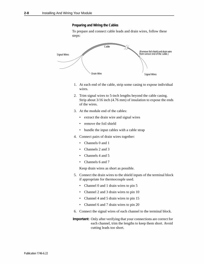
Preparing and Wiring the Cables
To prepare and connect cable leads and drain wires, follow these steps:
1. At each end of the cable, strip some casing to expose individual wires.
2. Trim signal wires to 5-inch lengths beyond the cable casing. Strip about 3/16 inch (4.76 mm) of insulation to expose the ends of the wires.
3. At the module end of the cables:
• extract the drain wire and signal wires
• remove the foil shield
• bundle the input cables with a cable strap
4. Connect pairs of drain wires together:
• Channels 0 and 1
• Channels 2 and 3
• Channels 4 and 5
• Channels 6 and 7
Keep drain wires as short as possible.
5. Connect the drain wires to the shield inputs of the terminal bloif appropriate for thermocouple used.
• Channel 0 and 1 drain wires to pin 5
• Channel 2 and 3 drain wires to pin 10
• Channel 4 and 5 drain wires to pin 15
• Channel 6 and 7 drain wires to pin 20
6. Connect the signal wires of each channel to the terminal bloc
(Remove foil shield and drain wire from sensor end of the cable.)
Cable
Signal WiresDrain Wire
Signal Wires
Important: Only after verifying that your connections are correct foeach channel, trim the lengths to keep them short. Avocutting leads too short.
Publication 1746-6.22

Installing And Wiring Your Module 2-9
7. Connect TB1 chassis ground connector to the nearest chassis mounting bolt with 14 gauge wire. (Looking at the face of the module, TB1 is near the lower part of the terminal block on the primary side of the PCB.)
8. At the sensor end of cables from thermocouple/mV devices:
• remove the drain wire and foil shield
• apply shrink wrap as an option
• connect to mV devices keeping the leads short
TB
1
Connect ground wire to TB1 before installing module.
Important: If noise persists, try grounding the opposite end of thecable. Ground one end only.
Publication 1746-6.22
2-10 Installing And Wiring Your Module
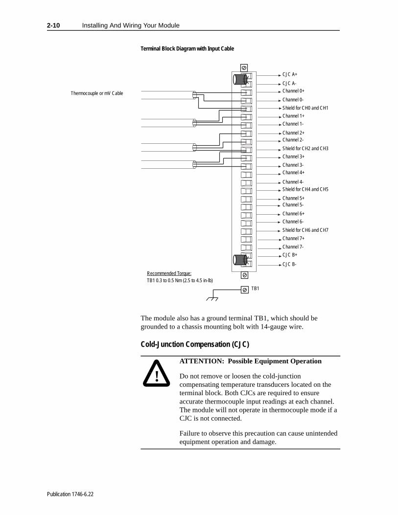
Terminal Block Diagram with Input Cable
The module also has a ground terminal TB1, which should be grounded to a chassis mounting bolt with 14-gauge wire.
Cold-Junction Compensation (CJC)
Thermocouple or mV Cable
CJC A+
CJC A-
CJC B-
CJC B+
Channel 0+
Channel 7-
Channel 7+
Channel 6-
Channel 6+
Channel 5-Channel 5+
Channel 4-
Channel 4+
Channel 3-
Channel 3+
Channel 2-Channel 2+
Channel 1-
Channel 1+
Channel 0-
Shield for CH0 and CH1
Shield for CH2 and CH3
Shield for CH4 and CH5
Shield for CH6 and CH7
TB1
Recommended Torque:TB1 0.3 to 0.5 Nm (2.5 to 4.5 in-lb)
!ATTENTION: Possible Equipment Operation
Do not remove or loosen the cold-junction compensating temperature transducers located on the terminal block. Both CJCs are required to ensure accurate thermocouple input readings at each channel. The module will not operate in thermocouple mode if a CJC is not connected.
Failure to observe this precaution can cause unintended equipment operation and damage.
Publication 1746-6.22

Installing And Wiring Your Module 2-11
n
een
To obtain accurate readings from each of the channels, the cold- junction temperature (temperature at the module’s terminal junctiobetween the thermocouple wire and the input channel) must be compensated for. Two cold-junction compensating sensors have bintegrated in the removable terminal block. They must remain installed.
Publication 1746-6.22

d
ule
s.
Chapter 3
Things To Consider Before Using Your Module
This chapter explains how the module and the SLC processor communicate through the processor’s I/O image tables. It also describes the module’s input filter characteristics. Topics discusseinclude:
• module ID code
• module addressing
• channel filter frequency selection
• channel turn-on, turn-off, and reconfiguration times
• response to slot disabling
Module ID Code The module ID code is unique number assigned to each 1746 I/Omodule. The ID code defines for the processor the type of I/O modand the number of words used in the processor’s I/O image table.
The module ID code for the 1746-NT8 module is 3533.
No special I/O configuration is required. The module ID automatically assigns the correct number of input and output word
Publication 1746-6.22

3-2 Things To Consider Before Using Your Module
ed a ch the
le .
Module Addressing The following memory map shows you how the SLC processor’s output and input tables are defined for the module.
Image Table
Output Image - Configuration Words
Eight words of the SLC processor’s output image table are reservfor the module. Output image words 0-7 are used to configure themodule’s input channels 0-7. Each output image word configures single channel and can be referred to as a configuration word. Eaword has a unique address based on the slot number assigned tomodule.
Example Address - If you want to configure channel 2 on the modulocated in slot 4 in the SLC chassis, your address would be O:4.2
Chapter 4, Channel Configuration, Data, and Status, gives you detailed bit information about the data content of the configurationword.
Channel 0 Configuration Word
Channel 1 Configuration Word
Channel 2 Configuration WordChannel 3 Configuration Word
Channel 4 Configuration Word
Channel 5 Configuration Word
Channel 6 Configuration Word
Channel 7 Configuration Word
Channel 0 Data or Status WordChannel 1 Data or Status Word
Channel 2 Data or Status Word
Channel 3 Data or Status Word
Channel 4 Data or Status Word
Channel 5 Data or Status Word
Channel 6 Data or Status Word
Channel 7 Data or Status Word
Output Image8 Words
Input Image8 Words
SLC 5/0XData Files
Output Scan
Input Scan
Slot e
Slot e
Output Image
Input Image
Word 0
Word 1
Word 2
Word 3
Word 4
Word 5
Word 6
Word 7
O:e.0
O:e.1
O:e.2
O:e.3
O:e.4
O:e.5
O:e.6
O:e.7
Word 0
Word 1
Word 2
Word 3
Word 4
Word 5
Word 6
Word 7
I:e.0
I:e.1
I:e.2
I:e.3
I:e.4
I:e.5
I:e.6
I:e.7
Address
AddressBit 15
Bit 15
Bit 0
Bit 0
Thermocouple Module
Image Table
O:4.2
Slot
Word
Publication 1746-6.22

Things To Consider Before Using Your Module 3-3
for el
data
s t
d the nel.
mber
se
or n at
es lter nel
ilter
Input Image - Data Words and Status Words
Eight words of the SLC processor’s input image table are reservedthe module. Input image words are multiplexed since each channhas one data word and one status word. The corresponding configuration word selects whether the channel status or channel is in the input image word.
Status bits for a particular channel reflect the configuration settingthat you entered into the configuration (output image) word for thachannel. To receive valid status, the channel must be enabled anmodule must have stored a valid configuration word for that chan
Each input image word has a unique address based on the slot nuassigned to the module.
Example Address - To obtain the status/data word of channel 2 (input word 2) of the module located in slot 4 in the SLC chassis uaddress I:4:2.
Chapter 4, Channel Configuration, Data, and Status, gives you detailed bit information about the content of the data word and thestatus word.
Channel Filter Frequency Selection
The thermocouple module uses a digital filter that provides high- frequency noise rejection for the input signals. The digital filter is programmable, allowing you to select from four filter frequencies feach channel. The digital filter provides the highest noise rejectiothe selected filter frequency. The graphs to follow show the input channel frequency response for each filter frequency selection.
Selecting a low value (i.e. 10 Hz) for the channel filter frequency provides the best noise rejection for a channel, but it also increasthe channel update time. Selecting a high value for the channel fifrequency provides lower noise rejection, but decreases the chanupdate time.
The following table shows the available filter frequencies, cut-off frequency, step response, and a DC effective resolution for each ffrequency.
I:4.2
Slot
Word
Word Delimiter
Element Delimiter
File Type
Publication 1746-6.22

3-4 Things To Consider Before Using Your Module
-off is
Cut-off frequency, Step Response Time, and Effective Resolution (Based on Filter Frequency)
The step response is calculated by a 4 x (1/filter frequency) settling time.
Channel Cut-Off Frequency
The channel filter frequency selection determines a channel’s cutfrequency, also called the -3 dB frequency. The cut-off frequency
Publication 1746-6.22

Things To Consider Before Using Your Module 3-5
Signal Attenuation with 10 Hz Input Filter
Signal Attenuation with 50 Hz Input Filter
0
-20
-40
-60
-80
-100
-120
-140
-160
-180
-2000
2.62 Hz Signal Frequency
-3 dB
10 20 30 40 50 60 Hz
Amplitude (in dB)
0
-20
-40
-60
-80
-100
-120
-140
-160
-180
-2000 50 100 150 200 250 300 Hz
13.1 Hz
-3 dB
Amplitude (in dB)
Signal Frequency
Publication 1746-6.22
3-6 Things To Consider Before Using Your Module
se. ach
he the by for
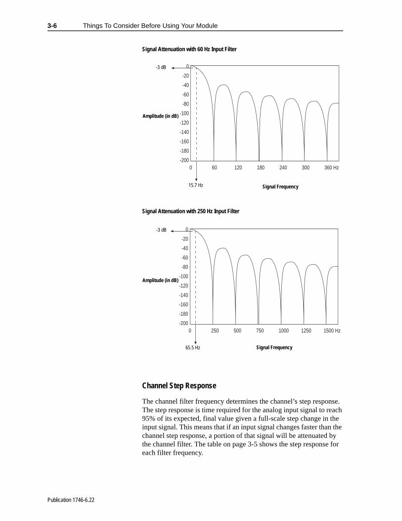
Signal Attenuation with 60 Hz Input Filter
Signal Attenuation with 250 Hz Input Filter
Channel Step Response
The channel filter frequency determines the channel’s step responThe step response is time required for the analog input signal to re95% of its expected, final value given a full-scale step change in tinput signal. This means that if an input signal changes faster thanchannel step response, a portion of that signal will be attenuated the channel filter. The table on page 3-5 shows the step responseeach filter frequency.
0
-20
-40
-60
-80
-100
-120
-140
-160
-180
-2000 60 120 180 240 300 360 Hz
-3 dB
15.7 Hz Signal Frequency
Amplitude (in dB)
0
-20
-40
-60
-80
-100
-120
-140
-160
-180
-2000 250 500 750 1000 1250 1500 Hz
-3 dB
Amplitude (in dB)
Signal Frequency65.5 Hz
Publication 1746-6.22

Things To Consider Before Using Your Module 3-7
Update Time The thermocouple module update time is defined as the time required for the module to sample and convert the input signals of all enabled input channels and make the resulting data values available to the SLC processor. It can be calculated by adding the sum of all enabled sample times, plus a CJC update time.
The following table shows the channel sampling time for each filter frequency. It also gives the CJC update time.
Channel Sampling Time
The times above include a settling time necessary between input channel readings. The sampling times for filter frequencies listed do not include a 45 msec open-circuit detection time utilized when the channel is configured for open-circuit detection. CJC open-circuit detection does not require the additional 45 msec settling time.
The fastest module update time occurs when only one channel with a 250 Hz filter frequency is enabled.
Module update time = 290 msec + 66 msec = 356 msec
The slowest module update time occurs when eight channels, each using a 10 Hz filter frequency, are enabled.
Module update time = 290 msec + 470 msec + 470 msec + 470 msec + 470 msec + 470 msec + 470 msec + 470 msec + 470 msec = 4.05 sec
Update Time Calculation Example
The following example shows how to calculate the module update time for the given configuration:
Channel 0 configured for 250 Hz filter frequency, enabled Channel 1 configured for 250 Hz filter frequency, enabled Channel 2 configured for 50 Hz filter frequency, enabled Channel 3 through 7 disabled
Sample Channel 0
Sample Channel 1
Sample Channel 2
Sample Channel 7
SampleCJC
Channel
Enabled Enabled Enabled Enabled
Channel 0 Disabled Channel 1 Disabled Channel 2 Disabled Channel 7 Disabled
Update CJC Calculate Previous
Calculate Previous
Calculate Previous
Calculate Previous
Channel Sampling Time for Each Filter Frequency (all values ±1 msec)
Channel Sampling Time
CJC Update Time 250 Hz Filter 60 Hz Filter 50 Hz Filter 10 Hz Filter
290 msec 66 msec 125 msec 140 msec 470 msec
Publication 1746-6.22
3-8 Things To Consider Before Using Your Module
per
to-
rs
e s
een
l
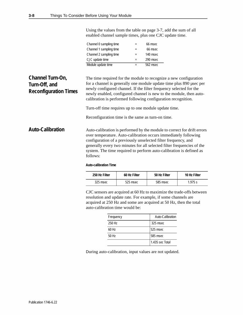
Using the values from the table on page 3-7, add the sum of all enabled channel sample times, plus one CJC update time.
Channel Turn-On, Turn-Off, and Reconfiguration Times
The time required for the module to recognize a new configuration for a channel is generally one module update time plus 890 µsec newly configured channel. If the filter frequency selected for the newly enabled, configured channel is new to the module, then aucalibration is performed following configuration recognition.
Turn-off time requires up to one module update time.
Reconfiguration time is the same as turn-on time.
Auto-Calibration Auto-calibration is performed by the module to correct for drift erroover temperature. Auto-calibration occurs immediately following configuration of a previously unselected filter frequency, and generally every two minutes for all selected filter frequencies of thsystem. The time required to perform auto-calibration is defined afollows:
Auto-calibration Time
CJC sensors are acquired at 60 Hz to maximize the trade-offs betwresolution and update rate. For example, if some channels are acquired at 250 Hz and some are acquired at 50 Hz, then the totaauto-calibration time would be:
During auto-calibration, input values are not updated.
Channel 0 sampling time = 66 msecChannel 1 sampling time = 66 msec
Channel 2 sampling time = 140 msecCJC update time = 290 msecModule update time = 562 msec
250 Hz Filter 60 Hz Filter 50 Hz Filter 10 Hz Filter
325 msec 525 msec 585 msec 1.975 s
Frequency Auto-Calibration
250 Hz 325 msec
60 Hz 525 msec
50 Hz 585 msec
1.435 sec Total
Publication 1746-6.22
Things To Consider Before Using Your Module 3-9
of nt
data ver, uts the
ed
Response to Slot Disabling
By writing to the status file in the modular SLC processor, you can disable any chassis slot. Refer to your SLC programming manual for the slot disable/enable procedure.
Input Response
When a thermocouple slot is disabled, the thermocouple module continues to update its input image table. However, the SLC processor does not read input from a module that is disabled. Therefore, when the processor disables the thermocouple module slot, the module inputs appearing in the processor image table remain in their last state, and the module’s updated image table is not read.When the processor re-enables the module slot, the current statethe module inputs are read by the processor during the subsequescan.
Output Response
The SLC processor may change the thermocouple module output(configuration) as it appears in the processor output image. Howethis data is not transferred to the thermocouple module. The outpare held in their last state. When the slot is re-enabled, the data inprocessor image is transferred to the thermocouple module.
!ATTENTION: POSSIBLE EQUIPMENT OPERATION
Always understand the implications of disabling a module before using the slot disable feature.
Failure to observe this precaution can cause unintendequipment operation.
Publication 1746-6.22
t
ay , rd
Chapter 4
Channel Configuration, Data, and Status
Read this chapter to:
• configure each input channel
• check each input channel’s configuration and status
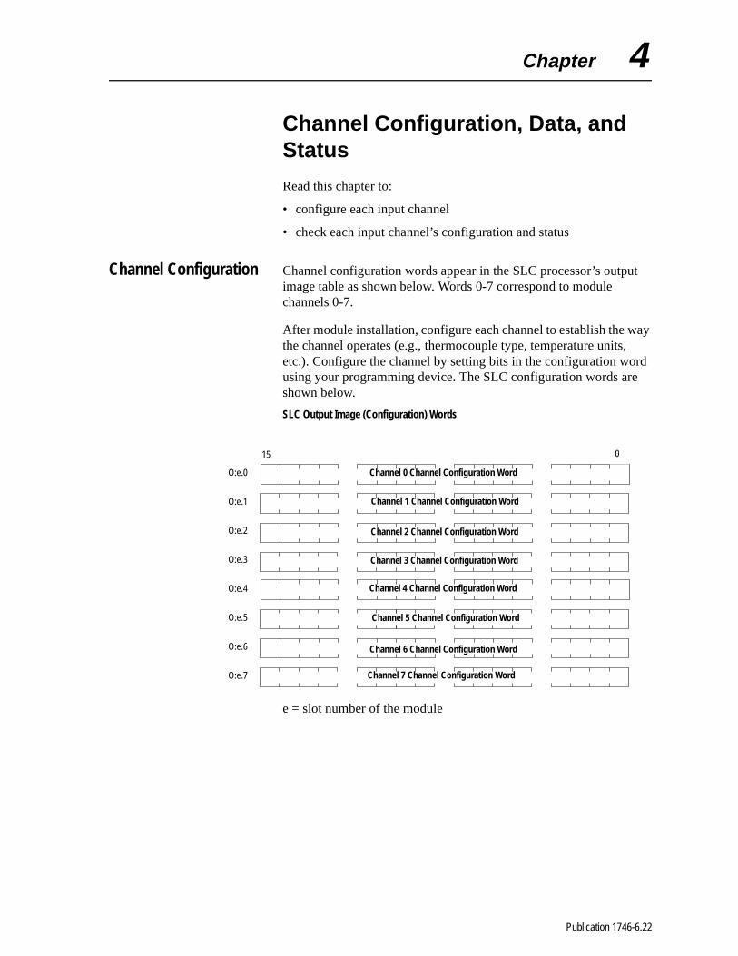
Channel Configuration Channel configuration words appear in the SLC processor’s outpuimage table as shown below. Words 0-7 correspond to module channels 0-7.
After module installation, configure each channel to establish the wthe channel operates (e.g., thermocouple type, temperature unitsetc.). Configure the channel by setting bits in the configuration wousing your programming device. The SLC configuration words areshown below.
SLC Output Image (Configuration) Words
e = slot number of the module
015
O:e.0
O:e.1
O:e.2
O:e.3
O:e.4
O:e.5
O:e.6
O:e.7
Channel 0 Channel Configuration Word
Channel 1 Channel Configuration Word
Channel 2 Channel Configuration Word
Channel 3 Channel Configuration Word
Channel 4 Channel Configuration Word
Channel 5 Channel Configuration Word
Channel 6 Channel Configuration Word
Channel 7 Channel Configuration Word
Publication 1746-6.22

4-2 Channel Configuration, Data, and Status
it
of at ion.
ble ce a
de
nes
in
en- ter
e r
g
nd el
nd
nd
The configuration word default settings are all zero. Next, we describe how you set configuration bits of a channel configuration word to set up the following channel parameters:
• data format such as engineering units, counts, or scaled for PID
• how the channel should respond to a detected open-input circu
• filter frequency selection
• temperature units in °C or °F
• whether the channel is enabled or disabled
• whether status or data information is selected for the module’s input image table.
Channel Configuration Procedure
The channel configuration word consists of bit fields, the settings which determine how the channel operates. This procedure lookseach bit field separately and helps configure a channel for operatRefer to the chart on page 4-4 and the bit field descriptions that follow for complete configuration information.
1. Determine which channels are used in your program and enathem. Place a one in bit 0 if the channel is to be enabled. Plazero in bit 0 if the channel is to be disabled.
2. Determine the input device type (J, K, etc. thermocouple) (ormV) for a channel and enter its respective four-digit binary coin bit field 1 through 4 of the channel configuration word.
3. Select a data format for the data word. Your selection determihow the analog input value from the A/D converter will be expressed in the data word. Enter your two-digit binary code bit field 5 and 6 of the channel configuration word.
4. Determine the desired state for the channel data word if an opcircuit condition is enabled and detected for that channel. Enthe two-digit binary code in bit field 7 and 8 of the channel configuration word.
5. If the channel is configured for thermocouple inputs, determinif the channel data word should read in degrees Fahrenheit odegrees Celsius and enter a one or a zero in bit 9 of the configuration word. If the channel is configured for a mV analosensor, enter a zero in bit 9.
6. Determine the desired input filter frequency for the channel aenter the two-digit binary code in bits 10 and 11 of the channconfiguration word. A lower filter frequency increases the channel update time, but also increases the noise rejection achannel resolution. A higher filter frequency decreases the channel update time, but also decreases the noise rejection aeffective resolution.
Publication 1746-6.22

Channel Configuration, Data, and Status 4-3
7. Ensure that bits 12 through 14 contain zeros.
8. Determine whether the channel input image word should contain data or status. Place a one in bit 15 if channel data is desired. Place a zero in bit 15 if status is desired.
9. Build the channel configuration word for every channel on each thermocouple/mV module repeating the procedures given in steps 1 through 8.
10. Enter this configuration into your ladder program and download it to the thermocouple module.
Publication 1746-6.22

4-4 Channel Configuration, Data, and Status
A detailed explanation appears in the following table:
Channel Configuration Word (O:e.0 through O:e.7) - Bit Definitions
Channel Enable
15 14 13 12 11 10 9 8 7 6 5 4 3 2 1 0
Channel Disable
Channel Enable
0
1
Input
Type
Thermocouple Type J 0 0 0 0
Thermocouple Type K 0 0 0 1
Thermocouple Type T 0 0 1 0
Thermocouple TypeE 0 0 1 1
Thermocouple Type R 0 1 0 0
Thermocouple TypeS 0 1 0 1
Thermocouple Type B 0 1 1 0
Thermocouple Type N 0 1 1 1
±50 mV 1 0 0 0
±100 mV 1 0 0 1
Invalid 1 0 1 0
Invalid 1 0 1 1
Invalid 1 1 0 0
Invalid 1 1 0 1
Invalid 1 1 1 0
CJC temperature 1 1 1 1
Data
Format
Engineering Units x 11 0 0
Engineering Units x 101 0 1
Scaled for PID 1 0
Proportional counts 1 1
Open Circuit
Zero on open circuit 0 0
Max. on open circuit 0 1
Min. on open circuit 1 0
Disabled 1 1
Temperature Units
Degrees C2 0
Degrees F2 1
Channel
filter
freq.
10 Hz input filter 0 0
50 Hz input filter 0 1
60 Hz input filter 1 0
250 Hz input filter 1 1
UnusedUnused3 0 0 0
Invalid 1 1 1
Input Image Type
Status Word 0
Data Word 1
1. For engineering units x1, values are expressed in 0.1 degrees or 0.01 mV. For engineering units x10, values are expressed in 1.0 degree or 0.1 mV.
2. When millivolt input type is selected, the bit setting for temperature units is ignored.
3. Ensure unused bits 12 through 14 are always set to zero.
Publication 1746-6.22

Channel Configuration, Data, and Status 4-5
mV
t
gnal.
he ts.
r s or
r ch is
r ted
Select Channel Enable (Bit 0)
Use the channel enable bit to enable a channel. The thermocouple module only scans enabled channels. To optimize module operation and minimize throughput times, unused channels should be disabled by setting the channel enable bit to zero (default value).
When set (1) the channel enable bit is used by the module to read the configuration word information selected. While the enable bit is set, modification of the configuration word may lengthen the module update time for one cycle. If any change is made to the configuration word, the change is reflected in the status word before new data is valid (described on page 4-11).
While the channel enable bit is cleared (0), the associated channel data/status word values are cleared. After the channel enable bit is set (1), the associated channel data/status word remains cleared until the thermocouple module sets the channel status bit (bit 0) in the channel status word.
Select Input Types (Bits 1 through 4)
The input type bit field lets you configure the channel for the type of input device you have connected to the module. Valid input devices are types J, K, T, E, R, S, B, and N thermocouple sensors and ±50and ±100mV analog input signals. The channel can also be configured to read the cold-junction temperature calculated for thaspecific channel. When the cold-junction compensation (CJC) temperature is selected, the channel ignores the physical input si
Select Data Format (Bits 5 and 6)
The data format bit field lets you define the expressed format for tchannel data word contained in the module input image. The datatypes are engineering units, scaled-for-PID, and proportional coun
The engineering units allow you to select from two resolutions, x1 ox10. For engineering units x1, values are expressed in 0.1 degree0.01mV. For engineering units x10, values are expressed in 1.0 degrees or 0.1mV. (Use the x10 setting to produce temperature readings in whole degrees Celsius or Fahrenheit.)
The scaled-for-PID value is the same for millivolt, thermocouple, and CJC input types. The input signal range is proportional to youselected input type and scaled into a 0 through 16,383 range, whistandard to the SLC PID algorithm.
The proportional counts are scaled to fit the defined temperature ovoltage range. The input signal range is proportional to your selecinput and scaled into a -32,768 to 32,767 range.
Publication 1746-6.22

4-6 Channel Configuration, Data, and Status
do nts uire ts.
al al or
ter
Using Scaled-for-PID and Proportional Counts
The thermocouple module provides eight options for displaying input channel data. These are 0.1°F, 0.1°C, 1°F, 1°C, 0.01 mV, 0.1 mV,Scaled-for-PID, and Proportional Counts. The first six options represent real Engineering Units displayed by the 1746-NT8 and not require explanation. The Scaled-for-PID and Proportional Couselections provide the highest NT8 display resolution, but also reqyou to manually convert the channel data to real Engineering Uni
The equations below show how to convert from Scaled-for-PID toEngineering Units, Engineering Units to Scaled-for-PID, ProportionCounts to Engineering Units, and Engineering Units to ProportionCounts. To perform the conversions, use the defined temperaturemillivolt range for the channel’s input type. See the Channel DataWord Format table on page 4-7. The lowest possible value for an input type is SLOW, and the highest possible value is SHIGH.
Effective Resolutions
The effective resolution for an input channel depends upon the filfrequency selected for that channel.
Publication 1746-6.22


4-8 Channel Configuration, Data, and Status
1746-NT8 Thermocouple Module - Channel Data Word Format
Data Format
InputType
Engineering Units x10 Engineering Units x1Scaled-for-
PIDProportional
Counts° Celsius ° Fahrenheit ° Celsius ° Fahrenheit
J -210 to +760 -346 to +1400 -2100 to +7600 -3460 to +14000 0 to +16383 -32768 to +32767
K -270 to +1370 -454 to +2498 -2700 to +13700 -4540 to +24980 0 to +16383 -32768 to +32767
T -270 to +400 -454 to +752 -2700 to +4000 -4540 to +7520 0 to +16383 -32768 to +32767
E -270 to +1000 -454 to +1832 -2700 to +10000 -4540 to +18320 0 to +16383 -32768 to +32767
R 0 to +1768 +32 to +3214 0 to +17680 +320 to+32140 0 to +16383 -32768 to +32767
S 0 to +1768 +32 to +2372 0 to +17680 +320 to +32140 0 to +16383 -32768 to +32767
B +300 to +1820 +572 to +3308 +3000 to +18200 +5720 to +3276.71 0 to +16383 -32768 to +32767
N 0 to +1300 +32 to +2372 0 to +13000 +320 to +23720 0 to +16383 -32768 to +32767
±50 mV2 -500 to +500 -500 to +500 -5000 to +5000 -5000 to +5000 0 to +16383 -32768 to +32767
±100 mV2 -1000 to +1000 -1000 to +1000 -10000 to +1000 -10000 to +10000 0 to +16383 -32768 to +32767
CJC Sensor -25 to +105 -13 to +221 -250 to +1050 -130 to +2210 0 to +16383 -32768 to +32767
1. Type B thermocouple cannot be represented in engineering units x1 (°F) above 3276.7°F. Software treats it as over range error.
2. When millivolts are selected, the temperature setting is ignored. Analog input data is the same for either °C or °F selection.
Publication 1746-6.22
Channel Configuration, Data, and Status 4-9
d e
it l
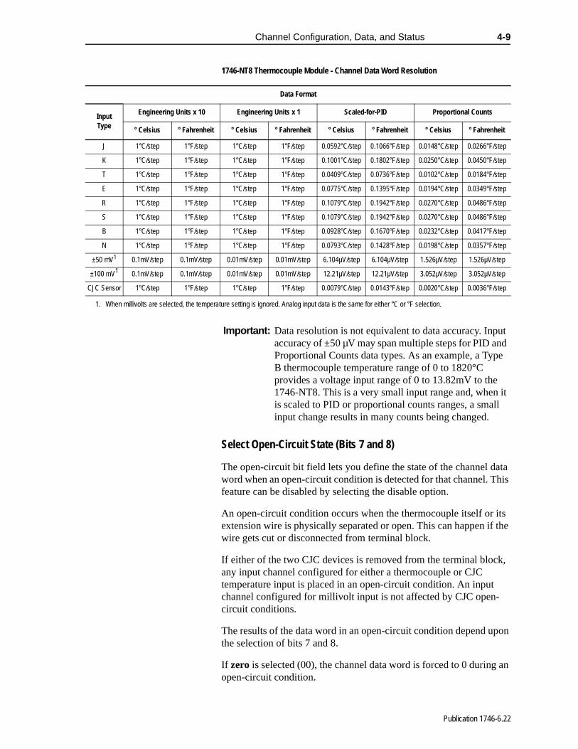
1746-NT8 Thermocouple Module - Channel Data Word Resolution
Select Open-Circuit State (Bits 7 and 8)
The open-circuit bit field lets you define the state of the channel data word when an open-circuit condition is detected for that channel. This feature can be disabled by selecting the disable option.
An open-circuit condition occurs when the thermocouple itself or its extension wire is physically separated or open. This can happen if the wire gets cut or disconnected from terminal block.
If either of the two CJC devices is removed from the terminal block, any input channel configured for either a thermocouple or CJC temperature input is placed in an open-circuit condition. An input channel configured for millivolt input is not affected by CJC open-circuit conditions.
The results of the data word in an open-circuit condition depend upon the selection of bits 7 and 8.
If zero is selected (00), the channel data word is forced to 0 during an open-circuit condition.
Data Format
InputType
Engineering Units x 10 Engineering Units x 1 Scaled-for-PID Proportional Counts
° Celsius ° Fahrenheit ° Celsius ° Fahrenheit ° Celsius ° Fahrenheit ° Celsius ° Fahrenheit
J 1°C/step 1°F/step 1°C/step 1°F/step 0.0592°C/step 0.1066°F/step 0.0148°C/step 0.0266°F/step
K 1°C/step 1°F/step 1°C/step 1°F/step 0.1001°C/step 0.1802°F/step 0.0250°C/step 0.0450°F/step
T 1°C/step 1°F/step 1°C/step 1°F/step 0.0409°C/step 0.0736°F/step 0.0102°C/step 0.0184°F/step
E 1°C/step 1°F/step 1°C/step 1°F/step 0.0775°C/step 0.1395°F/step 0.0194°C/step 0.0349°F/step
R 1°C/step 1°F/step 1°C/step 1°F/step 0.1079°C/step 0.1942°F/step 0.0270°C/step 0.0486°F/step
S 1°C/step 1°F/step 1°C/step 1°F/step 0.1079°C/step 0.1942°F/step 0.0270°C/step 0.0486°F/step
B 1°C/step 1°F/step 1°C/step 1°F/step 0.0928°C/step 0.1670°F/step 0.0232°C/step 0.0417°F/step
N 1°C/step 1°F/step 1°C/step 1°F/step 0.0793°C/step 0.1428°F/step 0.0198°C/step 0.0357°F/step
±50 mV1 0.1mV/step 0.1mV/step 0.01mV/step 0.01mV/step 6.104µV/step 6.104µV/step 1.526µV/step 1.526µV/step
±100 mV1 0.1mV/step 0.1mV/step 0.01mV/step 0.01mV/step 12.21µV/step 12.21µV/step 3.052µV/step 3.052µV/step
CJC Sensor 1°C/step 1°F/step 1°C/step 1°F/step 0.0079°C/step 0.0143°F/step 0.0020°C/step 0.0036°F/step
1. When millivolts are selected, the temperature setting is ignored. Analog input data is the same for either °C or °F selection.
Important: Data resolution is not equivalent to data accuracy. Input accuracy of ±50 µV may span multiple steps for PID anProportional Counts data types. As an example, a TypB thermocouple temperature range of 0 to 1820°C provides a voltage input range of 0 to 13.82mV to the 1746-NT8. This is a very small input range and, whenis scaled to PID or proportional counts ranges, a smalinput change results in many counts being changed.
Publication 1746-6.22

4-10 Channel Configuration, Data, and Status
e
rs
the
date ted
n-
do
,
nt
Selecting maximum forces the (01) channel data word value to its full scale value during an open-circuit condition. The full scale value is determined by the selected input type and data format.
Selecting minimum forces the (10) channel data word value to its low scale value during an open-circuit condition. The low scale value is determined by the selected input type and data format.
Disabling the open-circuit selection (11) may result in unintended operation on a failure. Generally, with the open-circuit option disabled, the data word remains unchanged. The open-circuit error bit and the channel LED flags the condition until the error is resolved.
For example, if channel one is configured as a thermocouple type when the CJC breaks in an open-circuit condition, if open-circuit detection is disabled, the data word remains unchanged. If the circuit selection is set at minimum, the data word is set to the low scale value for the range and format.
Select Temperature Units (Bit 9)
The temperature units bit lets you select temperature engineering units for thermocouple and CJC input types. Units are either degrees Celsius (°C) or degrees Fahrenheit (°F). This bit field is only activfor thermocouple and CJC input types. It is ignored when millivoltinputs types are selected.
Select Channel Filter Frequency (Bits 10 and 11)
The channel filter frequency bit field lets you select one of four filteavailable for a channel. The filter frequency affects the channel update time and noise rejection characteristics. A smaller filter frequency increases the channel update time, but also increases noise rejection and channel resolution. A larger filter frequency decreases the noise rejection, but also decreases the channel uptime and channel resolution. Guidelines for filter frequency are lisbelow.
Important: Enabling the open-circuit function adds approximately45 msec to the channel update time. Disabling the opecircuit detection removes the time adder. CJC sensorsnot require the additional time; thus it is recommendedthat when using a channel for CJC sensor acquisitionthe open-circuit selection is enabled.
Important: If you are using engineering units (x1 mode) and Fahrenheit temperature units (i.e. 0.1°F), the full scaletemperature for thermocouple type B is not achievablewith 16-bit signed numerical representation. An over- range error occurs for that channel if it tries to represethe full scale value. The maximum representable temperature is 3276.7°F (instead of 3308°F).
Publication 1746-6.22

Channel Configuration, Data, and Status 4-11
0).
rd. e
• 250 Hz setting provides minimal noise filtering.
• 60 Hz setting provides 60 Hz AC line noise filtering.
• 50 Hz setting provides 50 Hz AC line noise filtering.
• 10 Hz setting provides both 50 Hz and 60 Hz AC line noise filtering.
When a CJC input type is selected, filter frequency is ignored. Tomaximize the speed versus resolution trade-off, CJC inputs are sampled at 60 Hz.
Unused Bits (Bits 12 through 14)
Bits 12-14 are not defined. Ensure these bits are always cleared (
Select Input Image Type (Bit 15)
The input image type bit allows you to select data or status information in the channel’s input image word. When set (1), the module places channel data in the corresponding input image woWhen the bit is cleared (0) the module places channel status in thcorresponding input image word.
Publication 1746-6.22

4-12 Channel Configuration, Data, and Status
s (0 lt or
on
Channel Data/Status Word
The actual thermocouple or millivolt input data values or channel status reside in I:e.0 through I:e.7 of the thermocouple module input image file. The data values present depend on the input type and data formats you have selected. When an input channel is disabled, its data word is reset (0).
Channel Status Checking
You can use the information provided in the status word to determine if the input configuration data for any channel is valid per your configuration in O:e.0 through O:e.7.
The channel status can be analyzed bit by bit. In addition to providing information about an enabled or disabled channel, each bit’s statuor 1) tells you how the input data from the thermocouple or millivoanalog sensor connected to a specific channel will be translated fyour application. The bit status also informs you of any error condition and can tell you what type of error occurred.
A bit-by-bit examination of the status word is provided in the chart the following page.
Channel 0 Channel Data/Status Word
Channel 1 Channel Data/Status Word
Channel 2 Channel Data/Status Word
Channel 3 Channel Data/Status Word
Channel 4 Channel Data/Status Word
Channel 5 Channel Data/Status Word
Channel 6 Channel Data/Status Word
Channel 7 Channel Data/Status Word
015
Module Input Image (Data/Status) Word
I:e.0
I:e.1
I:e.2
I:e.3
I:e.4
I:e.5
I:e.6
I:e.7
Publication 1746-6.22

Channel Configuration, Data, and Status 4-13
Channel 0-7 Status Word (I:e.0 through I:e.7) - Bit Definitions
15 14 13 12 11 10 9 8 7 6 5 4 3 2 1 0
Channel
Status
Channel Disable
Channel Enable
0
1
Input
Type
Thermocouple Type J 0 0 0 0
Thermocouple Type K 0 0 0 1
Thermocouple Type T 0 0 1 0
Thermocouple TypeE 0 0 1 1
Thermocouple Type R 0 1 0 0
Thermocouple TypeS 0 1 0 1
Thermocouple Type B 0 1 1 0
Thermocouple Type N 0 1 1 1
±50 mV 1 0 0 0
±100 mV 1 0 0 1
Invalid 1 0 1 0
Invalid 1 0 1 1
Invalid 1 1 0 0
Invalid 1 1 0 1
Invalid 1 1 1 0
CJC temperature 1 1 1 1
Data
Format
Engineering Units x 1 0 0
Engineering Units x 10 0 1
Scaled for PID 1 0
Proportional counts 1 1
Open
Circuit
Zero on open circuit 0 0
Max. on open circuit 0 1
Min. on open circuit 1 0
Disabled 1 1
Temperature Units
Degrees C 0
Degrees F 1
Channelfilterfrequency
10 Hz input filter 0 0
50 Hz input filter 0 1
60 Hz input filter 1 0
250 Hz input filter 1 1
Open-circuit error
No error 0
Open circuit detected 1
Under-range error
No error 0
Under range condition 1
Over-range error
No error 0
Over range condition 1
Channel
error
No error 0
Channel error 1
Note: It takes one timing cycle to complete an update. (Refer to Chapter 3 for module update times.)
Publication 1746-6.22

Channel Configuration, Data, and Status 4-15
Under-Range Error (Bit 13)
This bit is set (1) whenever a configured channel detects an under-range condition for the channel data. An under-range condition exists when the input value is equal to or below the specified lower limit of the particular sensor connected to that channel.
Over-Range Error (Bit 14)
This bit is set (1) whenever a configured channel detects an over-range condition for the channel data. An over-range condition exists when the input value is equal to or above the specified upper limit of the particular sensor connected to that channel.
Channel Error (Bit 15)
This bit is set (1) whenever a configured channel detects an error in the configuration word, or an error has occurred while acquiring the A/D data value. If during the auto-calibration process, the module detects an out-of-range condition for the filter frequency selected for the channel, the channel error bit is set. An out-of-range condition occurring during auto-calibration would be the result of an overly noisy environment, whereby the module cannot maintain accuracy specifications, thus flagging an error. The error bit is cleared when the error condition is resolved. The channel data word is not updated during a period of auto-calibration filter frequency tolerance errors.
Publication 1746-6.22
.
e
Chapter 5
Programming Examples
Earlier chapters explained how the configuration word defines the way a channel operates. This chapter shows the programming required to configure the module. It also provides you with segments of ladder logic specific to unique situations that might apply to your programming requirements. The example segments include:
• basic example
• automatic monitoring thermocouples and CJC sensors
• verifying channel configuration changes
• interfacing to the PID instruction
• monitoring channel status bits
• PLC 5 example with NT8 in remote I/O rack
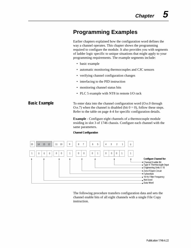
Basic Example To enter data into the channel configuration word (O:e.0 through O:e.7) when the channel is disabled (bit 0 = 0), follow these stepsRefer to the table on page 4-4 for specific configuration details.
Example - Configure eight channels of a thermocouple module residing in slot 3 of 1746 chassis. Configure each channel with thsame parameters.
Channel Configuration
The following procedure transfers configuration data and sets thechannel enable bits of all eight channels with a single File Copy instruction.
1 1
0
0 0 1 0 0 0 1 0 0 0 1
15 14 13 12 11 10 9 8 7 6 5 4 3 2 1
0 0 0
Configure Channel for:Channel Enable BitType K Thermocouple InputEngineering Units X 10Zero if Open CircuitFahrenheit10 Hz Filter FrequencyNot UsedData Word
Publication 1746-6.22
5-2 Programming Examples
Procedure
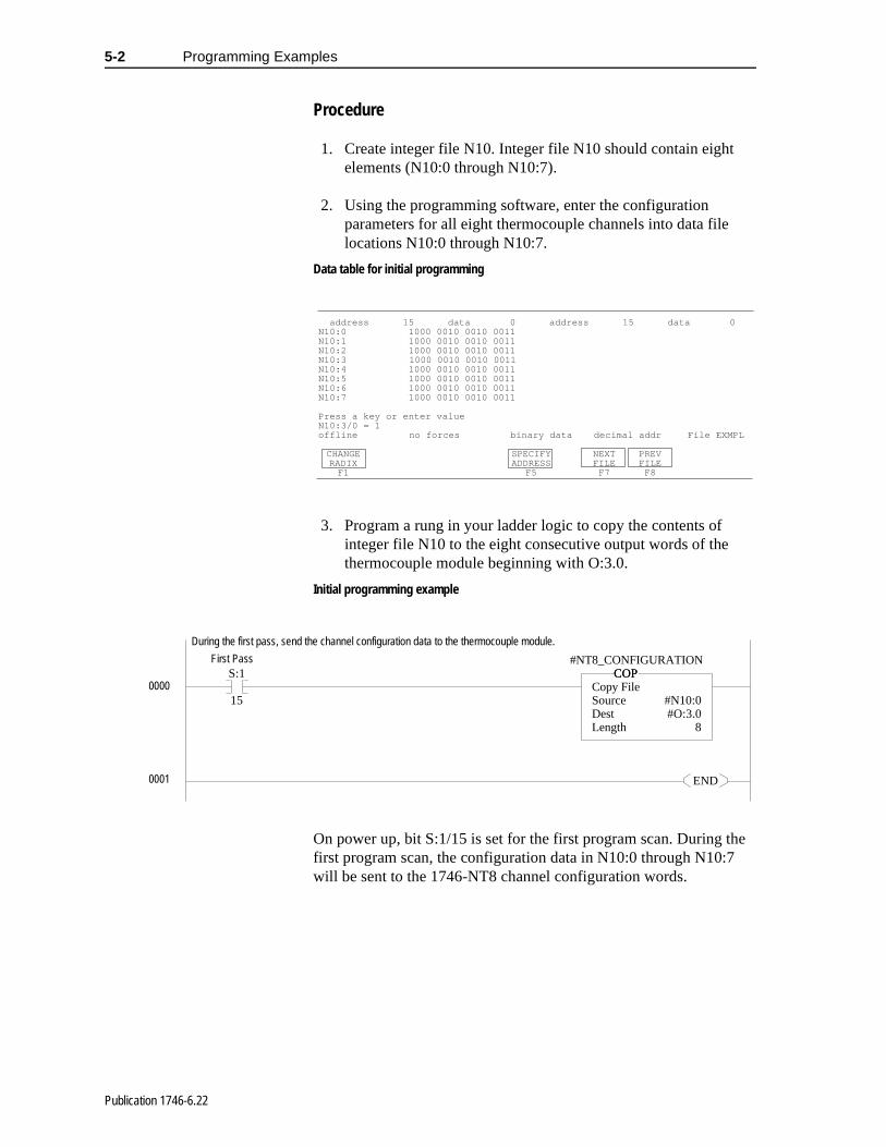
1. Create integer file N10. Integer file N10 should contain eight elements (N10:0 through N10:7).
2. Using the programming software, enter the configuration parameters for all eight thermocouple channels into data file locations N10:0 through N10:7.
Data table for initial programming
3. Program a rung in your ladder logic to copy the contents of integer file N10 to the eight consecutive output words of the thermocouple module beginning with O:3.0.
Initial programming example
On power up, bit S:1/15 is set for the first program scan. During the first program scan, the configuration data in N10:0 through N10:7 will be sent to the 1746-NT8 channel configuration words.
address 15 data 0 address 15 data 0N10:0 1000 0010 0010 0011N10:1 1000 0010 0010 0011N10:2 1000 0010 0010 0011N10:3 1000 0010 0010 0011N10:4 1000 0010 0010 0011N10:5 1000 0010 0010 0011N10:6 1000 0010 0010 0011N10:7 1000 0010 0010 0011
Press a key or enter valueN10:3/0 = 1offline no forces binary data decimal addr File EXMPL
CHANGE SPECIFY NEXT PREVRADIX ADDRESS FILE FILE
F1 F5 F7 F8
S:1
15
COPCopy FileSource #N10:0Dest #O:3.0Length 8
COP#NT8_CONFIGURATION
END
During the first pass, send the channel configuration data to the thermocouple module.
First Pass
0000
0001
Publication 1746-6.22

Programming Examples 5-3
Automatic Monitoring Thermocouples and CJC Sensors
The following example explains how to change data in the channel configuration word when the channel is currently enabled.
Example - Execute a dynamic configuration change to channel 0 of the thermocouple module located in slot 1 of a 1746 chassis. Periodically (e.g., every 60 seconds) change from monitoring an external type K thermocouple to monitoring the CJC sensors mounted on the terminal block. The CJC reading gives a good indication of what the temperature is inside the control cabinet. Finally, set channel 0 back to type K thermocouple.
Verifying Channel Configuration Changes
When executing a dynamic channel configuration change, there is always a delay from the time the ladder program makes the change to the time the 1746-NT8 supplies a data word using that new configuration information. Also, the ladder program should use the thermocouple temperature data location N10:20 for thermocouple temperature readings and data location N10:12 for CJC temperature readings.
Important: During configuration alteration, the state of each modified channel can not be determined until after one module update time.
Note: N10:2/1 through N10:2/4 have the input type for type K Thermocouple (0001). N10:8/1 through N10:8/4 have the input type for CJC Temperature Sensor (1111).
Publication 1746-6.22

5-4 Programming Examples
S:1
15
COPCopy FileSource #N10:0Dest #O:1.0Length 8
COP#NT8_CONFIGURATION
UB3:6
4
CHECKING_CJC
B3:6
4
CHECKING_CJCMOV
MoveSource I:1.0
3744<Dest N10:20 3744<
MOVCH0_TEMP
COPCopy FileSource #I:1.1Dest #N10:21Length 7
COP
T11:0
DN
CJC_CYCLE_TMR/DN
EN
DN
TONTimer On DelayTimer T11:0Time Base 1.0Preset 60<Accum 20<
TONCJC_CYCLE_TMR
T11:0
DN
CJC_CYCLE_TMR/DNMOV
MoveSource N10:8 -32737<Dest O:1.0 -32767<
MOVNT8_CONFIGURATION
LB3:6
4
CHECKING_CJC
During the first pass, send the channel configuration data to the thermocouple module.First Pass
If not Checking CJC, copy Channel 0 temperature data into data location for use. Temperature control logic should use N10:20 rather than the TC input image (I:1.0) to eliminate problems during CJC checking.
Copy temperature data from Channels 1-7 to data registers for use.
Repeating 60 seconds timer (T11:0) which starts the CJC check cycle.
Every 60 seconds, start CJC check cycle by changing Channel 0 configuration word and latching Checking CJC bit (B3/100).
0000
0003
0004
0002
0001
Publication 1746-6.22
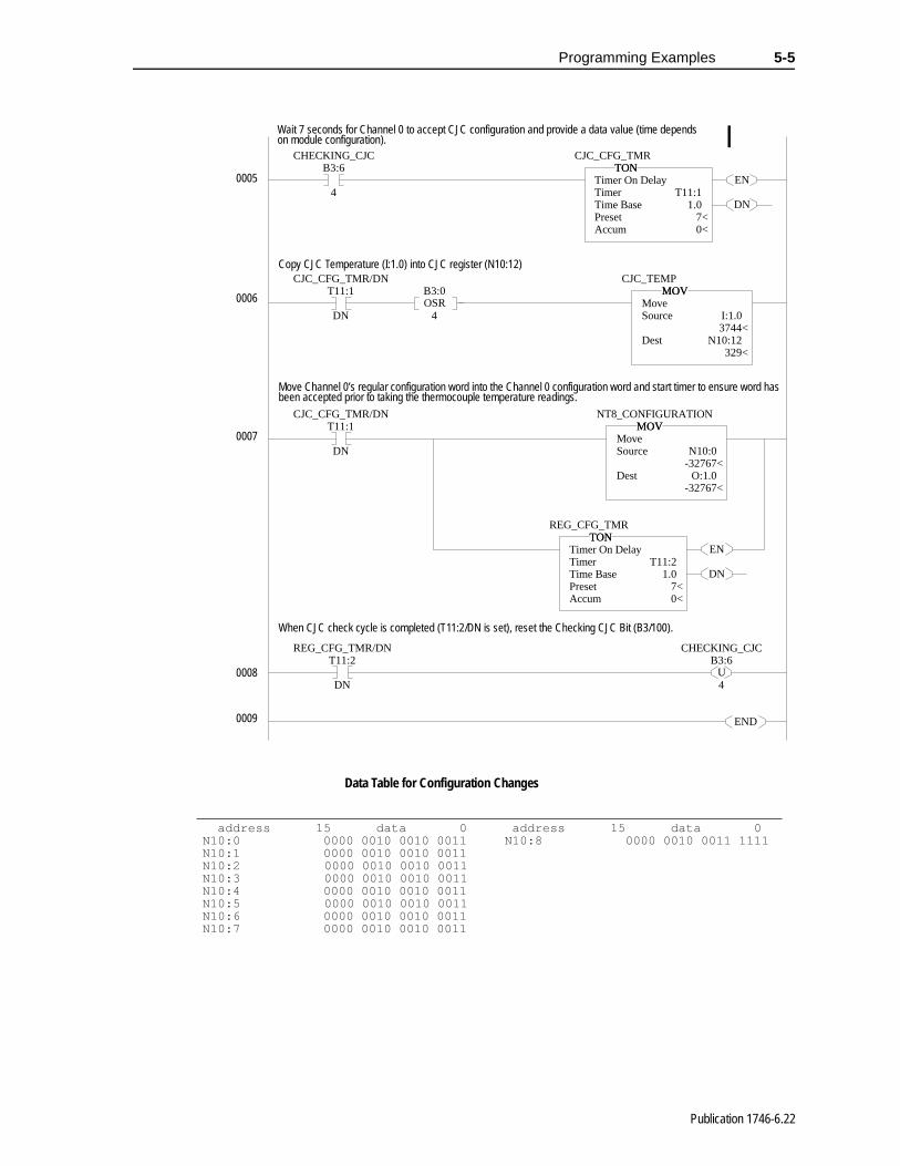
Programming Examples 5-5
Data Table for Configuration Changes
B3:6
4
CHECKING_CJC
EN
DN
TONTimer On DelayTimer T11:1Time Base 1.0Preset 7<Accum 0<
TONCJC_CFG_TMR
T11:1
DN
CJC_CFG_TMR/DN
OSRB3:0
4
MOVMoveSource I:1.0 3744<Dest N10:12 329<
MOVCJC_TEMP
T11:1
DN
CJC_CFG_TMR/DNMOV
MoveSource N10:0 -32767<Dest O:1.0 -32767<
MOVNT8_CONFIGURATION
EN
DN
TONTimer On DelayTimer T11:2Time Base 1.0Preset 7<Accum 0<
TONREG_CFG_TMR
T11:2
DN
REG_CFG_TMR/DN
UB3:6
4
CHECKING_CJC
END
Wait 7 seconds for Channel 0 to accept CJC configuration and provide a data value (time depends on module configuration).
Copy CJC Temperature (I:1.0) into CJC register (N10:12)
Move Channel 0’s regular configuration word into the Channel 0 configuration word and start timer to ensure word has been accepted prior to taking the thermocouple temperature readings.
When CJC check cycle is completed (T11:2/DN is set), reset the Checking CJC Bit (B3/100).
0005
0009
0008
0007
0006
address 15 data 0 address 15 data 0N10:0 0000 0010 0010 0011 N10:8 0000 0010 0011 1111N10:1 0000 0010 0010 0011N10:2 0000 0010 0010 0011N10:3 0000 0010 0010 0011N10:4 0000 0010 0010 0011N10:5 0000 0010 0010 0011N10:6 0000 0010 0010 0011N10:7 0000 0010 0010 0011
Publication 1746-6.22

5-6 Programming Examples
ate put
tion
the
After a channel configuration word is changed by the ladder logic, the module may not update the processor’s input image until one updtime later. In order to ensure that the program is using the proper indata, the ladder logic should wait one update time plus one calibratime to ensure that the new input data matches the channel configuration requested. The above table shows how to calculateupdate time and autocalibration time for the channel configurationbeing used.
Update Time Calculation
Ch 0 Update Time 0.470
Ch 0 Open Circuit Check 0.045
Ch 1 Update Time 0.470
Ch 1 Open Circuit Check 0.045
Ch 2 Update Time 0.470
Ch 2 Open Circuit Check 0.045
Ch 3 Update Time 0.470
Ch 3 Open Circuit Check 0.045
Ch 4 Update Time 0.470
Ch 4 Open Circuit Check 0.045
Ch 5 Update Time 0.470
Ch 5 Open Circuit Check 0.045
Ch 6 Update Time 0.470
Ch 6 Open Circuit Check 0.045
Ch 7 Update Time 0.470
Ch 7 Open Circuit Check 0.045
CJC Checking 0.290
Update Time 4.410
Autocalibration Time Calculation
Auto-Calibration for 10 Hz 1.975
Auto-Calibration for 60 Hz 0.525
Total Auto-Calibration 2.500
Max Time Between Updates 6.910
Publication 1746-6.22
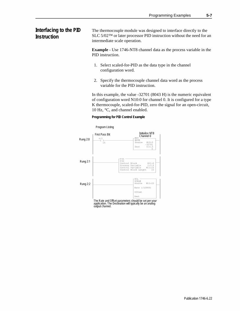
Programming Examples 5-7
an
the
ent e
it,
Interfacing to the PID Instruction
The thermocouple module was designed to interface directly to the SLC 5/02™ or later processor PID instruction without the need forintermediate scale operation.
Example - Use 1746-NT8 channel data as the process variable inPID instruction.
1. Select scaled-for-PID as the data type in the channel configuration word.
2. Specify the thermocouple channel data word as the process variable for the PID instruction.
In this example, the value -32701 (8043 H) is the numeric equivalof configuration word N10:0 for channel 0. It is configured for a typK thermocouple, scaled-for-PID, zero the signal for an open-circu10 Hz, °C, and channel enabled.
Programming for PID Control Example
MOVMOVESource N10:0
-32701Dest O:3.0
0
s:1 ] [ 15
PIDPIDControl Block N11:0Process Variable I:3.0Control Variable N11:23Control Block Length 23
SCLSCALESource N11:23
Rate [/10000]
Offset
Dest
Program Listing
First Pass Bit Initialize NT8Channel 0
Rung 2:0
Rung 2:2
Rung 2:1
The Rate and Offset parameters should be set per your application. The Destination will typically be an analog output channel.
Publication 1746-6.22

5-8 Programming Examples
Monitoring Channel Status Bits
The following example shows how to monitor the open-circuit error bits of each channel and set an alarm in the processor if one of the thermocouples opens. An open-circuit error can occur if the thermocouple breaks, one of the thermocouple wires gets cut or disconnected from the terminal block, or if the CJC sensors are not installed or are damaged.
The example shows how to automatically switch between reading the channel status words and channel sensor data words. Specifically, this example shows a simple method of utilizing a timer to periodically switch between reading the channel status and data words.
The program utilizes a timer accumulator value to determine when to set up the configuration words and when to read in the channel status and channel data information. The channel status information is copied from the I:2.0 to I:2.7 registers into registers N7:10 to N7:17. The channel data information is copied from I:2.0 to I:2.7 into registers N7:0 to N7:7. This allows sensor data and channel status information to be accessed at any time from these registers. However, when the module channels are configured to read sensor data, the channel status words (as reflected in N7:10 to N7:17) are not being dynamically updated, and vice-versa.
Important: If a CJC input is not installed or is damaged, all enabled thermocouple alarms are set, and all enabled thermocouple channel LEDs flash.
Publication 1746-6.22

Programming Examples 5-9
Monitoring Channel Status Bits Example
S:1
15
COPCopy FileSource #N10:0Dest #O:1.0Length 8
COP#NT8_CH_CNF
FLLFill FileSource 0Dest #N10:20Length 8
FLL#NT8_CH0_STS_FLAGS
CLRClearDest B3:7 0000000000000001<
CLR
B3:6
4
NT8_CHECKING_STSCOP
Copy FileSource #I:1.0Dest #N10:30Length 8
COP#NT8_LAST_TEMP_READ
T11:0
DN
NT8_STS_CHECK_TMR/DN
EN
DN
TONTimer On DelayTimer T11:0Time Base 1.0Preset 60<Accum 10<
TONNT8_STS_CHECK_TMR
T11:0
DN
NT8_STS_CHECK_TMR/DN
LB3:6
4
NT8_CHECKING_STS
COPCopy FileSource #N10:10Dest #O:1.0Length 8
COP#NT8_CH_CNF
B3:6
4
NT8_CHECKING_STS
EN
DN
TONTimer On DelayTimer T11:1Time Base 1.0Preset 7<Accum 0<
TONNT8_STS_CNF_TMR
During 1st program scan, copy thermocouple channel configuration words (N10:0 - N10:7) to NT8. In addition, initialize channel error registers (N10:20 - N10:27) and Error Flags (B3/112 - B3/119).
If the NT8 is not checking channel status, store the thermocouple readings in the NT8 last channel reading registers (N10:37). These registers should be used in the remainder of the program (e.g. for temperature control) instead of the NT8 I/O image location.
T11:0 is a repeating 60-second timer which initiates the NT8 channel status check.
Every 60 seconds, initiate a NT8 channel status check by latching the NT8 channel status checking bit and copying the “Status check” configuration words (N10:10 - N10:7) to the NT8 configuration words.
After copying the “Status Check configuration words” start a 7-second timer (T11:1) to allow the NT8 to update its I/O image to the channel status words. The time required for the NT8 to update its I/O image is dependent on the NT8 configuration. Note, the time required be greater than the channel update time including the autocalibration time.
0004
0000
0001
0002
0003
Publication 1746-6.22
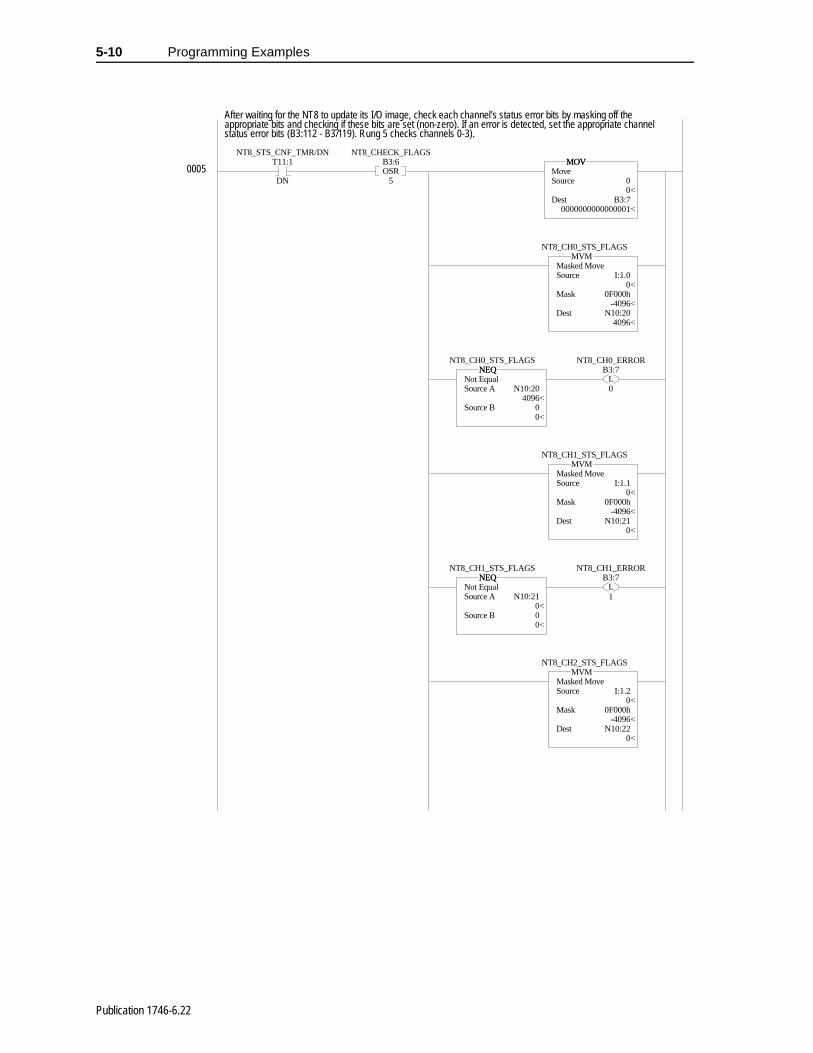
5-10 Programming Examples
T11:1
DN
NT8_STS_CNF_TMR/DN
OSRB3:6
5
NT8_CHECK_FLAGSMOV
MoveSource 0 0<Dest B3:7 0000000000000001<
MOV
MVMMasked MoveSource I:1.0
0<Mask 0F000h -4096<Dest N10:20 4096<
MVMNT8_CH0_STS_FLAGS
NEQNot EqualSource A N10:20
4096<Source B 0 0<
NEQNT8_CH0_STS_FLAGS
LB3:7
0
NT8_CH0_ERROR
MVMMasked MoveSource I:1.1 0<Mask 0F000h -4096<Dest N10:21
0<
MVMNT8_CH1_STS_FLAGS
NEQNot EqualSource A N10:21 0<Source B 0 0<
NEQNT8_CH1_STS_FLAGS
LB3:7
1
NT8_CH1_ERROR
MVMMasked MoveSource I:1.2 0<Mask 0F000h -4096<Dest N10:22 0<
MVMNT8_CH2_STS_FLAGS
After waiting for the NT8 to update its I/O image, check each channel’s status error bits by masking off the appropriate bits and checking if these bits are set (non-zero). If an error is detected, set the appropriate channel status error bits (B3:112 - B3/119). Rung 5 checks channels 0-3).
0005
Publication 1746-6.22

Programming Examples 5-11
NEQNot EqualSource A N10:22 0<Source B 0 0<
NEQNT8_CH2_STS_FLAGS
LB3:7
2
NT8_CH2_ERROR
MVMMasked MoveSource I:1.3 0<Mask 0F000h -4096<Dest N10:23 0<
MVMNT8_CH3_STS_FLAGS
NEQNot EqualSource A N10:23 0<Source B 0 0<
NEQNT8_CH3_STS_FLAGS
LB3:7
3
NT8_CH3_ERROR
T11:1 B3:6
DN 6
NT8_STS_CNF_TMR/DN NT8_CHECK_FLAGS2 MVM
Masked MoveSource I:1.4 0<Mask 0F000h -4096<Dest N10:24 0<
MVMNT8_CH4_STS_FLAGS
NEQNot EqualSource A N10:24 0<Source B 0 0<
NEQNT8_CH4_STS_FLAGS
LB3:7
4
NT8_CH4_ERROR
MVMMasked MoveSource I:1.5 0<Mask 0F000h -4096<Dest N10:25 0<
MVMNT8_CH5_STS_FLAGS
After waiting for the NT8 to update its I/O image, check each channel’s status error bits by masking off the appropriate bits and checking if these bits are set (non-zero). If an error is detected, set the appropriate channel status error bits (B3:112 - B3/119). Rung 6 checks channels 4 - 7.
0006 OSR
Publication 1746-6.22
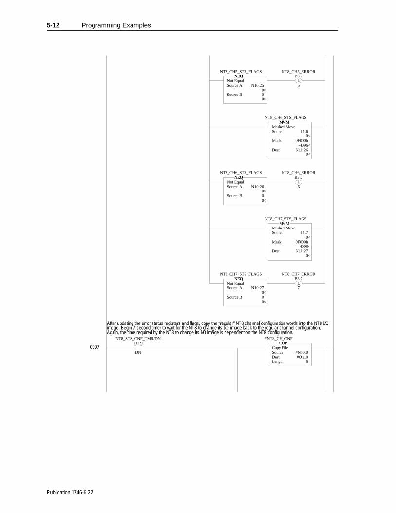
5-12 Programming Examples
NEQNot EqualSource A N10:25 0<Source B 0 0<
NEQNT8_CH5_STS_FLAGS
LB3:7
5
NT8_CH5_ERROR
MVMMasked MoveSource I:1.6 0<Mask 0F000h -4096<Dest N10:26 0<
MVMNT8_CH6_STS_FLAGS
NEQNot EqualSource A N10:26 0<Source B 0 0<
NEQNT8_CH6_STS_FLAGS
LB3:7
6
NT8_CH6_ERROR
MVMMasked MoveSource I:1.7 0<Mask 0F000h -4096<Dest N10:27 0<
MVMNT8_CH7_STS_FLAGS
NEQNot EqualSource A N10:27 0<Source B 0 0<
NEQNT8_CH7_STS_FLAGS
LB3:7
7
NT8_CH7_ERROR
T11:1
DN
NT8_STS_CNF_TMR/DNCOP
Copy FileSource #N10:0Dest #O:1.0Length 8
COP#NT8_CH_CNF
After updating the error status registers and flags, copy the “regular” NT8 channel configuration words into the NT8 I/O image. Begin 7-second timer to wait for the NT8 to change its I/O image back to the regular channel configuration. Again, the time required by the NT8 to change its I/O image is dependent on the NT8 configuration.
0007
Publication 1746-6.22
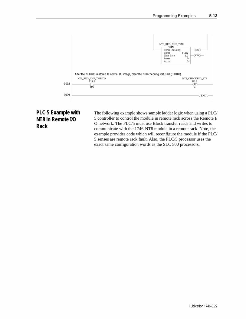
Programming Examples 5-13
PLC 5 Example with NT8 in Remote I/O Rack
The following example shows sample ladder logic when using a PLC/5 controller to control the module in remote rack across the Remote I/O network. The PLC/5 must use Block transfer reads and writes to communicate with the 1746-NT8 module in a remote rack. Note, the example provides code which will reconfigure the module if the PLC/5 senses are remote rack fault. Also, the PLC/5 processor uses the exact same configuration words as the SLC 500 processors.
EN
DN
TONTimer On DelayTimer T11:2Time Base 1.0Preset 7<Accum 0<
TONNT8_REG_CNF_TMR
T11:2
DN
NT8_REG_CNF_TMR/DN
UB3:6
4
NT8_CHECKING_STS
END
After the NT8 has restored its normal I/O image, clear the NT8 checking status bit (B3/100).
0008
0009
Publication 1746-6.22
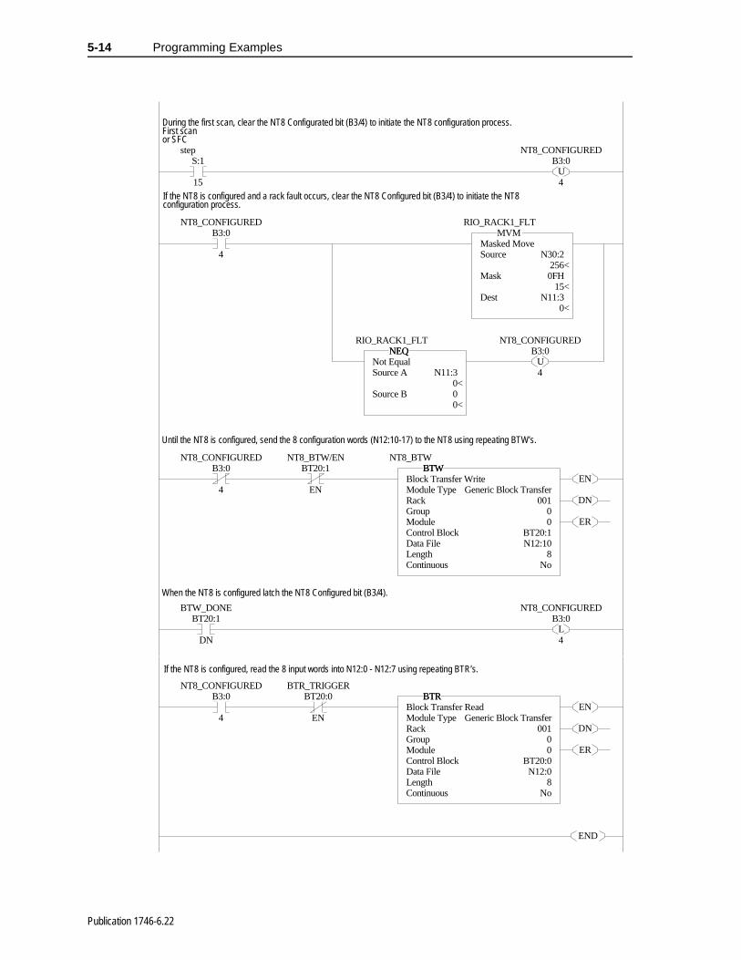
5-14 Programming Examples
S:1
15
step
UB3:0
4
NT8_CONFIGURED
B3:0
4
NT8_CONFIGUREDMVM
Masked MoveSource N30:2 256<Mask 0FH 15<Dest N11:3 0<
MVMRIO_RACK1_FLT
NEQNot EqualSource A N11:3 0<Source B 0 0<
NEQRIO_RACK1_FLT
UB3:0
4
NT8_CONFIGURED
B3:0
4
NT8_CONFIGUREDBT20:1
EN
NT8_BTW/EN
EN
DN
ER
BTWBlock Transfer WriteModule Type Generic Block TransferRack 001Group 0Module 0Control Block BT20:1Data File N12:10Length 8Continuous No
BTWNT8_BTW
BT20:1
DN
BTW_DONE
LB3:0
4
NT8_CONFIGURED
B3:0
4
NT8_CONFIGUREDBT20:0
EN
BTR_TRIGGER
EN
DN
ER
BTRBlock Transfer ReadModule Type Generic Block TransferRack 001Group 0Module 0Control Block BT20:0Data File N12:0Length 8Continuous No
BTR
END
During the first scan, clear the NT8 Configurated bit (B3/4) to initiate the NT8 configuration process.First scanor SFC
If the NT8 is configured and a rack fault occurs, clear the NT8 Configured bit (B3/4) to initiate the NT8 configuration process.
Until the NT8 is configured, send the 8 configuration words (N12:10-17) to the NT8 using repeating BTW’s.
When the NT8 is configured latch the NT8 Configured bit (B3/4).
If the NT8 is configured, read the 8 input words into N12:0 - N12:7 using repeating BTR’s.
Publication 1746-6.22
el-en-
her -2
for g
it g
ault d.
Chapter 6
Troubleshooting Your Module
This chapter describes troubleshooting with channel-status and module-status LEDs. It explains the types of conditions that might cause the module to flag an error and suggests what corrective action you could take. Topics include:
• module and channel diagnostics
• LED indicators
• Interpreting I/O error codes
• troubleshooting flowchart
Module and Channel Diagnostics
The module operates at two levels:
• module level
• channel level
Module-level operation includes functions such as powerup, configuration, and communication with the SLC processor. Channlevel operation includes functions such as data conversion and opcircuit detection. The module performs internal diagnostics at bothlevels and immediately indicates detected error conditions with eitof its status LEDs. See the LED troubleshooting tables on page 6for LED operation.
Module Diagnostics at Powerup
At module powerup, the module performs a series of internal diagnostic tests. If the module detects a failure, the module statusLED remains off.
Channel Diagnostics
When a channel is enabled, the module checks for a valid configuration. Then on each scan of its inputs, the module checksout-of-range and open-circuit fault conditions of its inputs includinthe CJC input.
When the module detects a failure of any channel diagnostic test,causes the channel status LED to blink and sets the correspondinchannel fault bit (bits 12-15 of the channel status word). Channel fbits and LEDs are self-clearing when fault conditions are correcte
Publication 1746-6.22

6-2 Troubleshooting Your Module
h
LED Indicators The module has nine LEDs; as shown below.
• eight channel-status LEDs, numbered to correspond with eacchannel
• one module-status LED
LED Troubleshooting Tables
Module-status LED
Module-status and Channel-status LED
Important: If you clear the channel enable bit, the channel statusbits are reset.
0
14
5
INPUT
23
67
LEDs for Channels 0-7LED for Module Status
Channel Status
Module
Thermocouple/mV
If Module Status LED
is:Then: Take this Corrective Action:
On The module is operating properly. No action required.
OffThe module is turned off, or it detected a module fault.
Cycle power. If the condition persists, call your local Allen-Bradley distributor for assistance.
Flashing Jumper may in wrong position Check jumper 1position.
If Module Status LED is:
And Channel Status LED is: Then: Take this Corrective Action:
On
On The channel is enabled No action required.
Flashing
The module detected: open-circuit condition, under-range condition, over-range condition
Examine error bits in status wordIf bit 12=1, the input has an open circuitIf bit 13=1, the input value is under rangeIf bit 14=1, the input value is over rangeIf bit 15=1, the channel has a diagnostic channel error
Off
The module is in power up, or the channel is disabled.
No action is required.
Publication 1746-6.22

Troubleshooting Your Module 6-3
g gh ns
le its ts.
on
ing
ected
Channel-status LEDs (Green)
The channel-status LED operates with status bits in the channel status word to indicate the following faults detected by the module:
• invalid channel configuration
• an open-circuit input
• out-of-range errors
• selected filter frequency data acquisition or auto-calibration errors
When the module detects any of the following fault conditions, it causes the channel-status LED to flash and sets the correspondinfault bit in the channel status word. Channel fault bits (bits 12 throu15) and channel-status LEDs are self-clearing when fault conditioare corrected.
Open-circuit Detection (Bit 12)
If open-circuit detection is enabled for an input channel, the modutests the channel for an open-circuit condition each time it scans input. Open-circuit detection is always performed for the CJC inpuPossible causes of an open circuit include:
• broken thermocouple or CJC sensor
• thermocouple or CJC sensor wire cut or disconnected
• millivolt input wire cut or disconnected
Out-of-Range Detection (Bit 13 for Under Range, bit 14 for Over Range)
The module tests all enabled channels for an out-of-range conditieach time it scans its inputs. Possible causes of an out-of-range condition include:
• the temperature is too hot or too cold for the thermocouple beused
• a type B thermocouple may be registering a °F value in Engineering Units x1 beyond the range allowed by the SLC processor (beyond 32,767) for the data word
• a CJC sensor may be damaged or the temperature being detby the CJC may be outside the CJC sensor range limits
Publication 1746-6.22

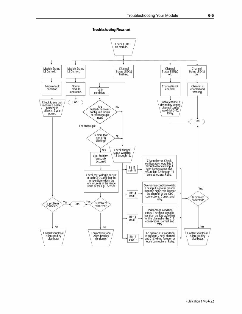
Troubleshooting Your Module 6-5
Troubleshooting Flowchart
.
Check LEDs on module.
Module Status LED(s) off.
Module Status LED(s) on.
Channel Status LED(s)
flashing.
Channel Status LED(s)
off.
Channel Status LED(s)
on.
Module fault condition.
Normal module
operation.Fault
condition.
Channel is not enabled.
Channel is enabled and
working.
Check to see that module is seated
properly in chassis. Cycle
power.
End.Are
faulted channel(s)configured for mV or thermocouple
input?
mV
Enable channel if desired by setting
channel config. word (bit 0=1).
Retry.
End.
NoIs more than one LED blinking?
Yes
CJC fault has probably occurred
Check channel status word bits 12 through 15.
Bit 15set (1)
Bit 12set (1)
Bit 14set (1)
Bit 13set (1)
Channel error. Check configuration word bits 1 through 4 for valid input type configuration and
ensure bits 12 through 14 are set to zero. Retry.
Over-range condition exists. The input signal is greater than the high scale limit for
the channel or the CJC connections. Correct and
retry.
Check that wiring is secure at both CJCs and that the
temperature within the enclosure is in the range limits of the CJC sensor.
Is problem corrected?
No
Yes
Under-range condition exists. The input signal is
less than the low scale limit for the channel or the CJC connections. Correct and
retry.
An open-circuit condition is present. Check channel and CJC wiring for open or loose connections. Retry.
Is problem corrected?
Yes
No
End.Is problem corrected?
Yes
No
Contact your local Allen-Bradley
distributor
Contact your local Allen-Bradley
distributor.
Contact your local Allen-Bradley
distributor.
Thermocouple
Publication 1746-6.22

70B
se nd
se
f
Chapter 7
Maintaining Your Module And Safety Considerations
Read this chapter to familiarize yourself with:
• preventive maintenance
• safety considerations
The National Fire Protection Association (NFPA) recommends maintenance procedures for electrical equipment. Refer to article of the NFPA for general safety-related work practices.
Preventive Maintenance
The printed circuit boards of your module must be protected fromdirt, oil, moisture, and other airborne contaminants. To protect theboards, install the SLC 500 system in an enclosure suitable for itsoperating environment. Keep the interior of the enclosure clean, awhenever possible, keep the enclosure door closed.
Also, regularly inspect the terminal connections for tightness. Looconnections may cause a malfunctioning of the SLC system or damage to the components.
Safety Considerations Safety is always the most important consideration. Actively think about the safety of yourself and others, as well as the condition oyour equipment. The following are some things to consider:
Indicator Lights – When the module status LED on your module is illuminated, your module is receiving power.
Activating Devices When Troubleshooting – Never reach into a machine to activate a device; the machine may move unexpectedly. Use a wooden stick.
!ATTENTION: Possible Loose Connections
Before inspecting connections, always ensure that incoming power is OFF.
Failure to observe this precaution can cause personal injury and equipment damage.
Publication 1746-6.22

7-2 Maintaining Your Module And Safety Considerations
,
n.
nal
-
2, y.
Standing Clear Of Machinery – When troubleshooting a problem with any SLC 500 system, have all personnel remain clear of machinery. The problem may be intermittent, and the machine may move unexpectedly. Have someone ready to operate an emergency stop switch.
Safety Circuits – Circuits installed on machinery for safety reasons (like over-travel limit switches, stop push-buttons, and interlocks) should always be hard-wired to the master control relay. These circuits should also be wired in series so that when any one circuit opens, the master control relay is de-energized, thereby removing power. Never modify these circuits to defeat their function. Serious injury or equipment damage may result.
Refer to your system’s Installation & Operation Manual for more information.
!ATTENTION: Possible Equipment Operation
Never reach into a machine to actuate a switch. Alsoremove all electrical power at the main power disconnect switches before checking electrical connections or inputs/outputs causing machine motio
Failure to observe these precautions can cause persoinjury or equipment damage.
!ATTENTION: Explosion Hazard
• Substitution of components may impair suitabilityfor Class 1 Division 2.
• Do not disconnect equipment unless power has been switched off or the area is known to be nonhazardous.
• When in hazardous locations, turn off power before replacing or wiring modules.
Note: This equipment is suitable for use in Class 1, Division groups A, B, C, and D or non-hazardous locations onl
Publication 1746-6.22

Appendix A
Module Specifications
This appendix lists the specifications for the 1746-NT8 Thermocouple/millivolt Input Module.
Electrical Specifications
Physical Specifications
Backplane Current Consumption 120 mA at 5V dc70 mA at 24Vdc
Backplane Power Consumption 2.28W maximum (0.6W at 5V dc, 1.68W at 24V dc)
Number of Channels 8 (backplane and channel-to-channel isolated)
I/O Chassis Location Any I/O module slot except 0
A/D Conversion Method Sigma-Delta Modulation
Input Filtering Low pass digital filter with programmable notch (filter) frequencies
Normal Mode Rejection (between [+] input and [-] input) Greater than 100 dB at 50/60 Hz
Common Mode Rejection (between input and ground) Greater than 100 dB at 50/60 Hz
Input Filter Cut-Off Frequencies 2.6 Hz at 10 Hz filter frequency13.1 Hz at 50 Hz filter frequency15.72 Hz at 60 Hz filter frequency65.5 Hz at 250 Hz filter frequency
Greater than 100 dB at 50/60 Hz
Calibration Module autocalibrates at power-up and approximately every two minutes afterward
Input Over-voltage Protection ±30V dc continuous 600W pulsed for 1 msec.
Isolation500V dc continuous between inputs and chassis ground and between inputs and backplane. 12.5V dc continuous between channels.
LED Indicators 9 green status indicators, one for each of 8 channels and one for module status
Module ID Code 3533
Recommended Cable:for thermocouple inputs…
for mV inputs…
Appropriate shielded twisted pair thermocouple extension wire1
Belden™ 8761 or equivalent
Maximum Wire Size One 14 AWG wire or two 22 AWG wires per terminal
1. Refer to the thermocouple manufacturer for the correct extention wire.
Publication 1746-6.22
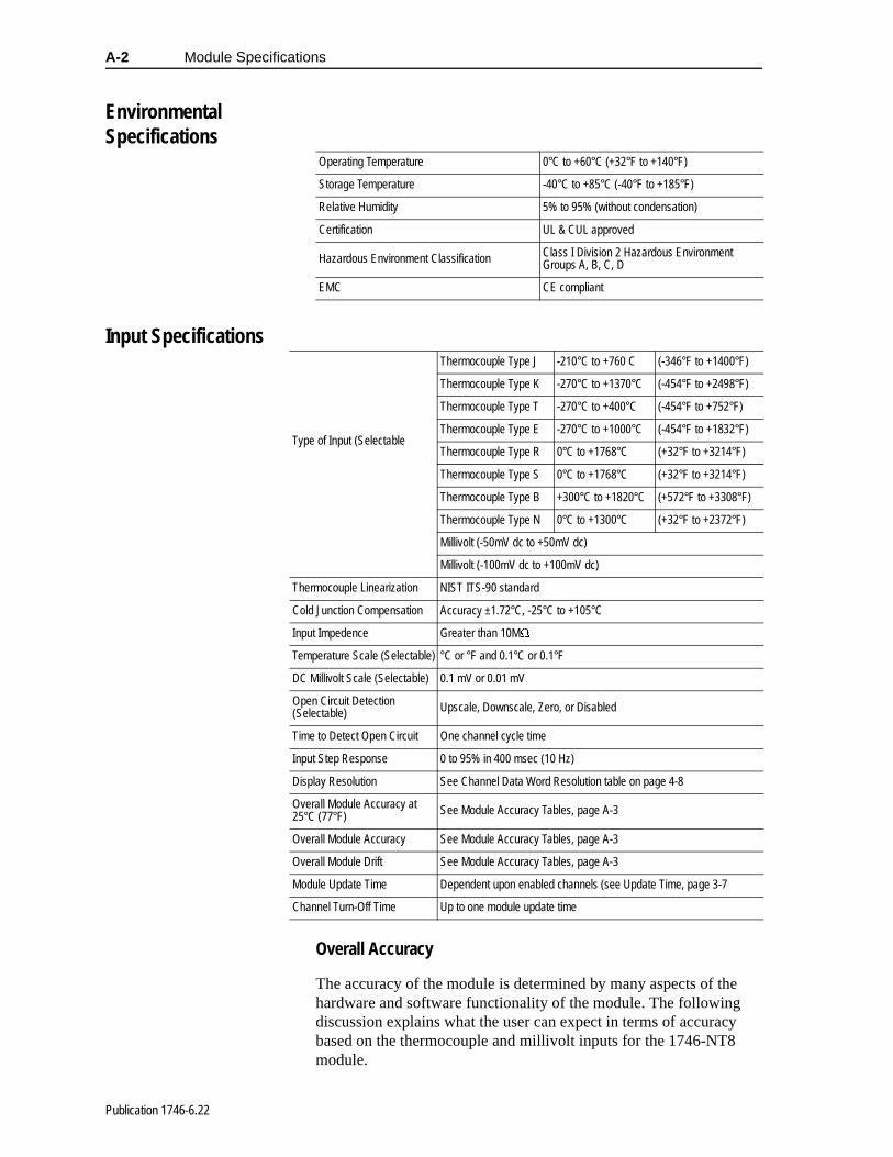
A-2 Module Specifications
Environmental Specifications
Input Specifications
Overall Accuracy
The accuracy of the module is determined by many aspects of the hardware and software functionality of the module. The following discussion explains what the user can expect in terms of accuracy based on the thermocouple and millivolt inputs for the 1746-NT8 module.
Operating Temperature 0°C to +60°C (+32°F to +140°F)
Storage Temperature -40°C to +85°C (-40°F to +185°F)
Relative Humidity 5% to 95% (without condensation)
Certification UL & CUL approved
Hazardous Environment Classification Class I Division 2 Hazardous Environment Groups A, B, C, D
EMC CE compliant
Type of Input (Selectable
Thermocouple Type J -210°C to +760 C (-346°F to +1400°F)
Thermocouple Type K -270°C to +1370°C (-454°F to +2498°F)
Thermocouple Type T -270°C to +400°C (-454°F to +752°F)
Thermocouple Type E -270°C to +1000°C (-454°F to +1832°F)
Thermocouple Type R 0°C to +1768°C (+32°F to +3214°F)
Thermocouple Type S 0°C to +1768°C (+32°F to +3214°F)
Thermocouple Type B +300°C to +1820°C (+572°F to +3308°F)
Thermocouple Type N 0°C to +1300°C (+32°F to +2372°F)
Millivolt (-50mV dc to +50mV dc)
Millivolt (-100mV dc to +100mV dc)
Thermocouple Linearization NIST ITS-90 standard
Cold Junction Compensation Accuracy ±1.72°C, -25°C to +105°C
Input Impedence Greater than 10M:
Temperature Scale (Selectable) °C or °F and 0.1°C or 0.1°F
DC Millivolt Scale (Selectable) 0.1 mV or 0.01 mV
Open Circuit Detection (Selectable) Upscale, Downscale, Zero, or Disabled
Time to Detect Open Circuit One channel cycle time
Input Step Response 0 to 95% in 400 msec (10 Hz)
Display Resolution See Channel Data Word Resolution table on page 4-8
Overall Module Accuracy at 25°C (77°F) See Module Accuracy Tables, page A-3
Overall Module Accuracy See Module Accuracy Tables, page A-3
Overall Module Drift See Module Accuracy Tables, page A-3
Module Update Time Dependent upon enabled channels (see Update Time, page 3-7
Channel Turn-Off Time Up to one module update time
Publication 1746-6.22
Module Specifications A-3
V
y
n the
” rded
, as he lt
The accuracies specified as follows include errors due to the cold junction compensation for thermocouples and hardware and software errors associated with the system. The hardware and software errors include calibration of the system and non-linearity of the ADC. For the sake of the calculations, the resolution of the ADC was assumed to be at least 16 bits (use of the 10 Hz, 50 Hz, and 60 Hz filter frequencies).
Millivolt
For millivolt inputs, the error is ±30 uV typical at 25°C, and ±120 umaximum over temperature for the 10 Hz, 50 Hz, and 60 Hz filterfrequencies. The 250 Hz filter frequency accuracy is highly dependent upon operating environment and may be worse in noisenvironments.
As with any high precision analog input device, system groundingdoes affect the accuracy of the readings. Care should be taken toensure that the proper filter frequency has been selected based oenvironmental conditions in which the module is to be used.
CJC compensation does not affect the millivolt inputs in terms of accuracy.
The following diagrams are provided to give a measure of “systemaccuracy using test data from a single test module. The tests recodeviation between measured and expected values. This data wastaken over an entire range of the thermocouple (or millivolt rangeapplicable) and over the module’s temperature range (0 - 60°C). Tmaximum deviation for each thermocouple temperature (or millivorange) was plotted.
Note: The 250 Hz frequency should not be applied to thermocouple inputs (See table on page 3-4).
Publication 1746-6.22

A-4 Module Specifications
0.00
5.00
10.00
15.00
20.00
25.00
30.00
35.00
40.00
45.00
50.00
-100-99
.92-99
.84-99
.76-99
.68 -99.6-99
.52-50
.16-50
.08 -50-49
.92-49
.84 -0.18 -0.
1-0.
02 0.06
0.14
49.8
49.88
49.96
50.04
50.12 50
.299
.5699
.6499
.72 99.8
99.88
99.96
uV Error
uV Err, ±100mV Span, Prop Cts, 60 Hz, 0°C
mV Input
uV D
evia
tion
0.00
5.00
10.00
15.00
20.00
25.00
30.00
35.00
40.00
45.00
50.00
-100-99
.92-99
.84-99
.76-99
.68 -99.6-99
.52-50
.16-50
.08 -50-49
.92-49
.84 -0.18 -0.
1-0.
02 0.06
0.14
49.8
49.88
49.96
50.04
50.12 50
.299
.5699
.6499
.72 99.8
99.88
99.96
uV Error
mV Input
uV D
evia
tion
uV Err, ±100mV Span, Prop Cts, 60 Hz, 25°C
Publication 1746-6.22

Module Specifications A-5
are/
Thermocouple
The following table provides the total error expected of the thermocouple based on the thermocouple type, and the given reference point, at 25°C. The calculations assumed typical hardwsoftware error and typical CJC accuracy at 25°C.
0.00
10.00
20.00
30.00
40.00
50.00
60.00
70.00
80.00
90.00
-100-99
.92-99
.84-99
.76-99
.68 -99.6-99
.52-50
.16-50
.08 -50-49
.92-49
.84 -0.18 -0.
1-0.
02 0.06
0.14
49.8
49.88
49.96
50.04
50.12 50
.299
.5699
.6499
.72 99.8
99.88
99.96
uV Error
uV Err, ±100mV Span, Prop Cts, 60 Hz, 60°C
mV Input
uV D
evia
tion
Thermocouple Type Thermocouple Reference Point Error
J +275°C (+527°F) ±1.4°C (±2.52°F)K +550°C (+1022°F) ±1.5°C (±2.7°F)T +65°C (+149°F) ±1.3°C (±2.34°F)
E +365°C (+689°F) ±1.0°C (±1.8°F)R +885°C (+1625°F) ±3.6°C (±6.48°F)S +885°C (+1625°F) ±3.4°C (±6.12°F)
B +1060°C (+1940°F) ±2.7°C (±4.86°F)N +500°C (+932°F) ±1.3°C (±2.34°F)
Publication 1746-6.22

A-6 Module Specifications
le es of
r a
C e
n
a of
The following table provides the total error expected over the temperature range of the module (0 to 60°C) for each thermocoupbased upon the type, and the given reference point, at the extremthe temperature range (0 or 60°C). The calculations are based onmaximum hardware/software error and maximum CJC inaccuracyover temperature.
The diagrams that follow for each thermocouple type give data fosample module over the input range of the thermocouple over temperature. Thermocouples are usually parabolic in their µV to °curves. Normally, at the ends of any given thermocouple range, thratio of change in temperature increases as a result of a change ivoltage. In other words, at the ends, a smaller change in voltage results in a larger change in °C. The data that follows gives an idea sample module’s error over the thermocouple range, versus at asingle reference point as provided with the tables above.
Thermocouple Type Thermocouple Reference Point Error
J +275°C (+527°F) ±3.0°C (±5.4°F)K +550°C (+1022°F) ±3.0°C (±5.4°F)
T +65°C (+149°F) ±3.4°C (±6.12°F)E +365°C (+689°F) ±2.5°C (±4.5°F)R +885°C (+1625°F) ±6.5°C (±11.7°F)
S +885°C (+1625°F) ±7.2°C (±12.96°F)B +1060°C (+1940°F) ±8.4°C (±15.12°F)N +500°C (+932°F) ±3.0°C (±5.4°F)
Note: The data was recorded at 60 Hz. Values at 10 Hz and 50 Hz would be comparable.
Publication 1746-6.22

Module Specifications A-7
0
0.5
1
1.5
2
2.5
3
3.5
4
4.5
-210
-150 -7
5 075
150
195
225
255
285
315
345
375
450
525
600
675
750
Channel Delta
Thermocouple J Deviations Over Temp
Degrees C TC Input
Degr
ees
C D
evia
tion
0
0.5
1
1.5
2
2.5
3
3.5
4
4.5
5
-202
-125 -2
5 75175
300
400
470
510
550
590
630
725
825
925
1025
1125
1225
1325
Channel Delta
Degrees C TC Input
Deg
rees
C D
evia
tion
Thermocouple K Deviations Over Temp
Publication 1746-6.22

A-8 Module Specifications
0
2
4
6
8
10
12
-252
-225
-175
-125 -7
5-40
-20 0
20 40 60 80100
120
140
160
225
275
325
375
Channel Delta
Degrees C TC Input
Degr
ees
C D
evia
tion
Thermocouple T Deviations Over Temp
0
1
2
3
4
5
6
7
8
-252
-200
-125 -5
0 25100
175
250
285
315
345
375
405
435
465
525
600
675
750
825
900
975
Channel Delta
Degrees C TC Input
Degr
ees
C D
evia
tion
Thermocouple E Deviations Over Temp
Publication 1746-6.22

Module Specifications A-9
0
2
4
6
8
10
12
0150
300
450
600
750
805
835
865
895
925
955
985
1100
1250
1400
1550
1700
Channel Delta
Degrees C TC Input
Degr
ees
C D
evia
tion
Thermocouple R Deviations Over Temp
0
2
4
6
8
10
12
0150
300
450
600
750
805
835
865
895
925
955
985
1100
1250
1400
1550
1700
Channel Data
Degrees C TC Input
Degr
ees
C D
evia
tion
Thermocouple S Deviations Over Temp
Publication 1746-6.22
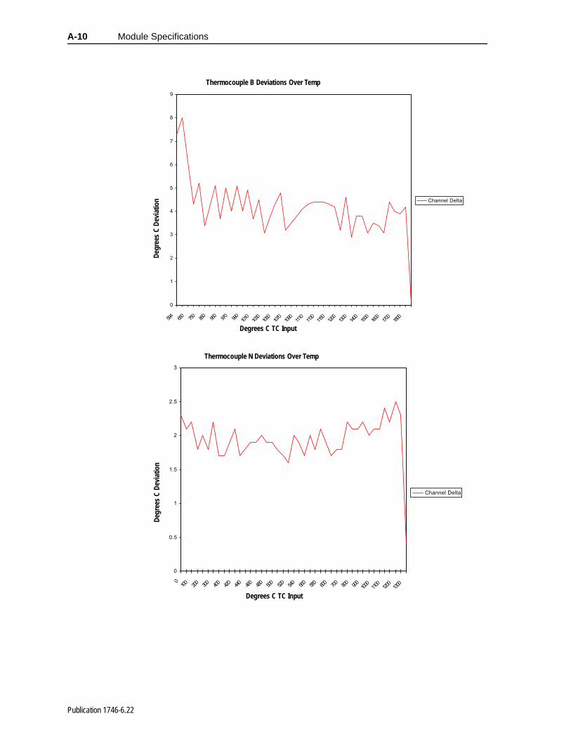
A-10 Module Specifications
0
1
2
3
4
5
6
7
8
9
594
650
750
850
950
970
990
1010
1030
1050
1070
1090
1110
1130
1150
1200
1300
1400
1500
1600
1700
1800
Channel Delta
Degrees C TC Input
Degr
ees
C D
evia
tion
Thermocouple B Deviations Over Temp
0
0.5
1
1.5
2
2.5
3
0100
200
300
400
420
440
460
480
500
520
540
560
580
600
700
800
900
1000
1100
1200
1300
Channel Delta
Degrees C TC Input
Degr
ees
C D
evia
tion
Thermocouple N Deviations Over Temp
Publication 1746-6.22

ed
or
ere
ple
Appendix B
Using Grounded Junction, Ungrounded Junction, and Exposed Junction Thermocouples
This appendix describes the types of thermocouples available and explains the trade-offs in using them with the 1746-NT8 module.
Thermocouple Types
There are three (3) types of thermocouple junctions:
• Grounded Junction - The measuring junction is physically connected to the protective sheath forming a completely sealintegral junction. If the sheath is metal (or electrically conductive), then there is electrical continuity between the junction and sheath. The junction is protected from corrosiveerosive conditions. The response time approaches that of theexposed junction type.
• Ungrounded Junction - The measuring junction is electricallyisolated from the protective metal sheath. This may also be referred to as an insulated junction. This type is often used whnoise would affect the reading and for frequent or rapid temperature cycling. The response time is longer than the grounded junction.
• Exposed Junction - The measuring junction does not have a protective metal sheath, so it is exposed. This junction style provides the fastest response time but leaves the thermocouwires unprotected against corrosive or mechanical damage.
Publication 1746-6.22
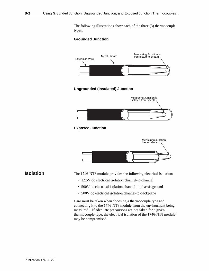
B-2 Using Grounded Junction, Ungrounded Junction, and Exposed Junction Thermocouples
e
The following illustrations show each of the three (3) thermocouple types.
Grounded Junction
Ungrounded (Insulated) Junction
Exposed Junction
Isolation The 1746-NT8 module provides the following electrical isolation:
• 12.5V dc electrical isolation channel-to-channel
• 500V dc electrical isolation channel-to-chassis ground
• 500V dc electrical isolation channel-to-backplane
Care must be taken when choosing a thermocouple type and connecting it to the 1746-NT8 module from the environment beingmeasured. . If adequate precautions are not taken for a given thermocouple type, the electrical isolation of the 1746-NT8 modulmay be compromised.
Measuring Junction is connected to sheathMetal Sheath
Extension Wire
Measuring Junction is isolated from sheath
Measuring Junction has no sheath
Publication 1746-6.22
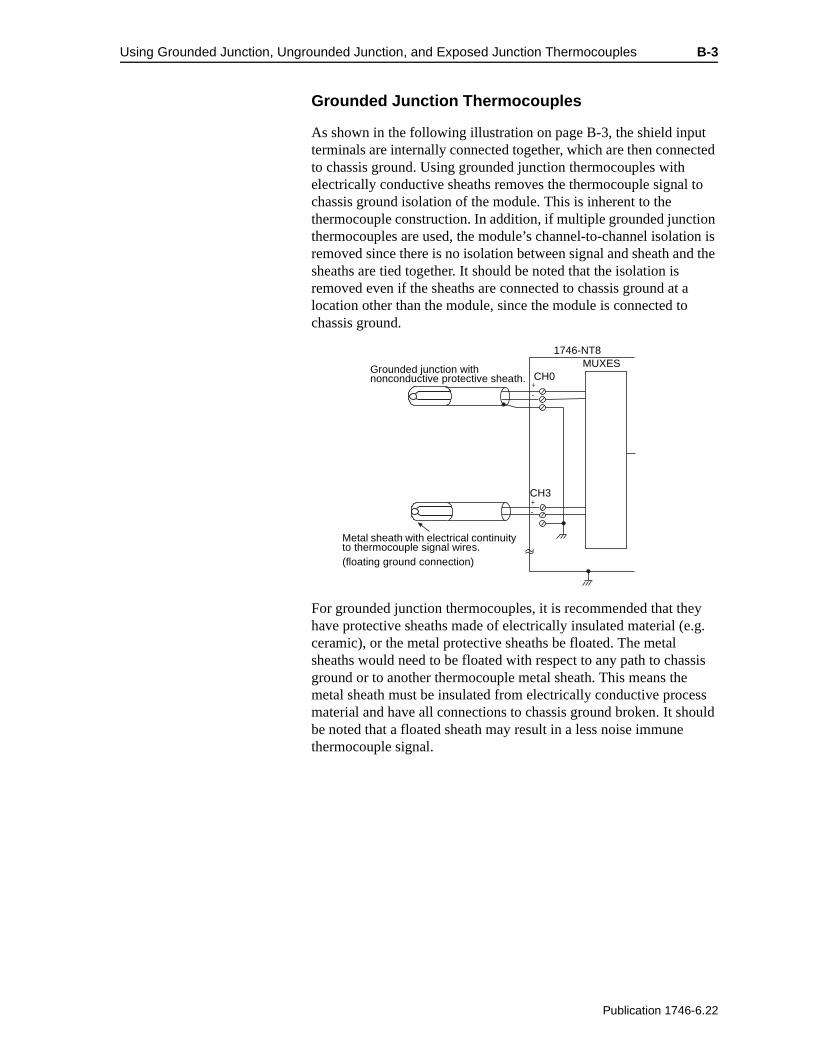
Using Grounded Junction, Ungrounded Junction, and Exposed Junction Thermocouples B-3
n is d the
a
y .g.
sis ss ould
Grounded Junction Thermocouples
As shown in the following illustration on page B-3, the shield input terminals are internally connected together, which are then connected to chassis ground. Using grounded junction thermocouples with electrically conductive sheaths removes the thermocouple signal to chassis ground isolation of the module. This is inherent to the thermocouple construction. In addition, if multiple grounded junction thermocouples are used, the module’s channel-to-channel isolatioremoved since there is no isolation between signal and sheath ansheaths are tied together. It should be noted that the isolation is removed even if the sheaths are connected to chassis ground at location other than the module, since the module is connected to chassis ground.
For grounded junction thermocouples, it is recommended that thehave protective sheaths made of electrically insulated material (eceramic), or the metal protective sheaths be floated. The metal sheaths would need to be floated with respect to any path to chasground or to another thermocouple metal sheath. This means themetal sheath must be insulated from electrically conductive procematerial and have all connections to chassis ground broken. It shbe noted that a floated sheath may result in a less noise immune thermocouple signal.
+-
+-
1746-NT8
Grounded junction with nonconductive protective sheath. CH0
MUXES
CH3
Metal sheath with electrical continuity to thermocouple signal wires.(floating ground connection)
Publication 1746-6.22
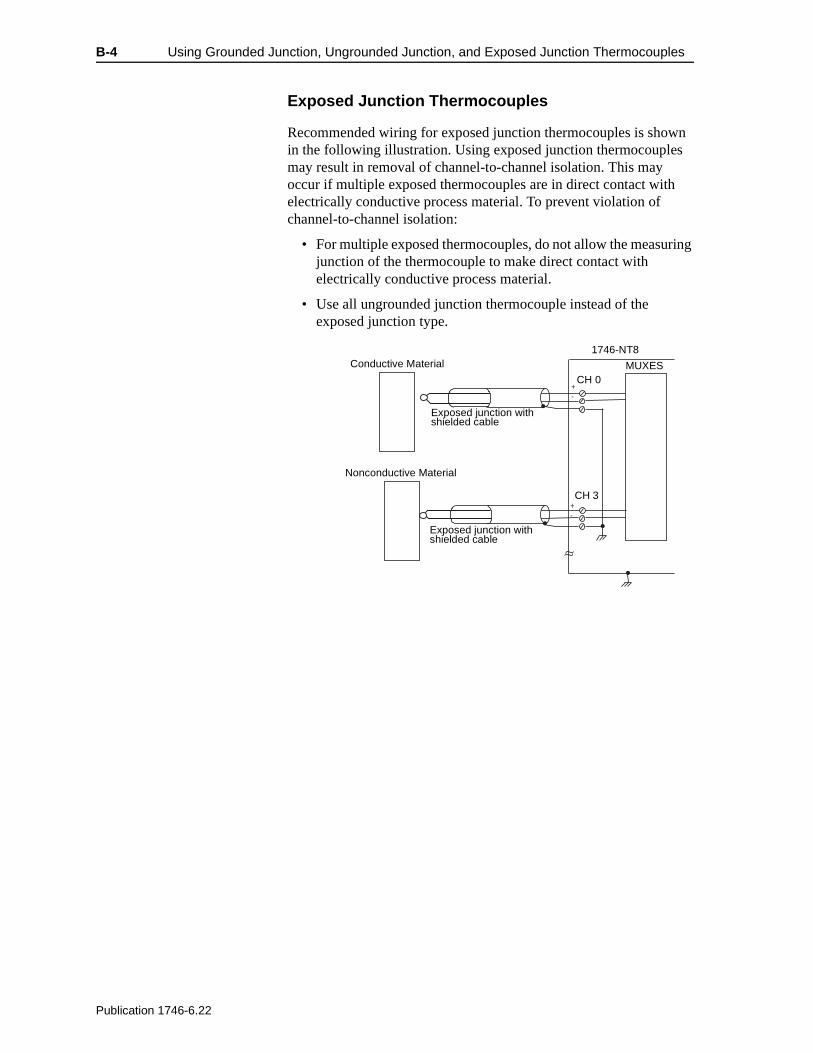
B-4 Using Grounded Junction, Ungrounded Junction, and Exposed Junction Thermocouples
ing
Exposed Junction Thermocouples
Recommended wiring for exposed junction thermocouples is shown in the following illustration. Using exposed junction thermocouples may result in removal of channel-to-channel isolation. This may occur if multiple exposed thermocouples are in direct contact with electrically conductive process material. To prevent violation of channel-to-channel isolation:
• For multiple exposed thermocouples, do not allow the measurjunction of the thermocouple to make direct contact with electrically conductive process material.
• Use all ungrounded junction thermocouple instead of the exposed junction type.
+-
+-
1746-NT8Conductive Material
Exposed junction with shielded cable
CH 0
CH 3
MUXES
Exposed junction with shielded cable
Nonconductive Material
Publication 1746-6.22

es
d
ies.
nd
in t o
he
g nel
Glossary
You should understand the following terms and abbreviations before using this guide.
A/D – Refers to analog-to-digital conversion. The conversion produces a digital value whose magnitude is proportional to the instantaneous magnitude of an analog input signal.
Attenuation – The reduction in magnitude of a signal as it passesthrough a system. The opposite of gain.
Channel – Refers to one of eight, small-signal analog input interfacto the modules’s terminal block. Each channel is configured for connection to a thermocouple or DC millivolt (mV) input device, anhas its own configuration and status words.
Chassis – A hardware assembly that houses devices such as I/O modules, adapter modules, processor modules, and power suppl
CJC – (Cold-Junction Compensation) The means by which the module compensates for the offset voltage error introduced by thetemperature at the junction between the thermocouple lead wire athe input terminal block (the cold junction).
Common mode rejection ratio (CMRR) – The ratio of a device’s differential voltage gain to common mode voltage gain. ExpresseddB, CMRR is a comparative measure of a device’s ability to rejecinterference caused by a voltage common to its terminal relative tground.
Common mode voltage – The voltage difference between the negative terminal and analog common during normal differential operation.
Configuration word – Contains the channel configuration information needed by the module to configure and operate eachchannel. Information is written to the configuration word through tlogic supplied in your ladder program.
Cut-off frequency – The frequency at which the input signal is attenuated 3 dB by the digital filter. Frequency components of theinput signal that are below the cut-off frequency are passed with under 3 dB of attenuation for low-pass filters.
dB (decibel) – A logarithmic measure of the ratio of two signal levels.
Data word – A 16-bit integer that represents the value of the analoinput channel. The channel data word is valid only when the chanis enabled and there are no channel errors.
Publication 1746-6.22

G-2 Glossary
d
r
h
et
s
to
en and
ed
te
r of
Digital filter – A low-pass filter of the A/D converter. The digital filter provides high-frequency noise rejection.
Effective resolution – The number of bits in the channel data wordthat do not vary due to noise.
Full-scale error (gain error) – The difference in slope between theactual and ideal analog transfer functions.
Full-scale range (FSR) – The difference between the maximum anminimum specified analog values.
Gain drift – The change in full-scale transition voltage measured over the operating temperature range of the module.
Input data scaling – Depends on the data format that you select fothe channel data word. You can select from scaled-for-PID or Engineering Units for millivolt, thermocouple, or CJC inputs, whicyou must compute to fit your application’s temperature or voltage resolution.
Local system – A control system with I/O chassis within several feof the processor, and using 1746-C7 or 1746-C9 ribbon cable for communication.
LSB (least significant bit) – The bit that represents the smallest value within a string of bits. The “weight” of this value is defined athe full-scale range divided by the resolution.
Multiplexer – A switching system that allows several input signalsshare a common A/D converter.
Normal mode rejection (differential mode rejection) – A logarithmic measure, in dB, of a device’s ability to reject noise signals between or among circuit signal conductors, but not betwethe equipment grounding conductor or signal reference structure the signal conductors.
Remote system – A control system where the chassis can be locatseveral thousand feet from the processor chassis. Chassis communication is via the 1747-SN Scanner and 1747-ASB RemoI/O Adapter.
Resolution – The smallest detectable change in a measurement, typically expressed in engineering units (e.g. 0.15°C) or as numbebits. For example, a 12-bit value has 4,096 possible counts. It cantherefore be used to measure 1 part in 4096.
Sampling time – The time required by the A/D converter to samplean input channel.
Publication 1746-6.22
Glossary G-3
nel
the
Status word – Contains status information about the channel’s current configuration and operational state. You can use this information in your ladder program to determine whether the chandata word is valid.
Step response time – The time required for the A/D signal to reach95% of its expected, final value, given a full-scale step change in input signal.
Update time – The time for the module to sample and convert a channel input signal and make the resulting value available to theSLC processor.
Publication 1746-6.22

Index I-i
A
Addressing 3-2, 3-4, 3-6, 3-7, 3-9,4-5, 4-6, 4-9, 4-10, 4-14, 4-15
Allen-Bradley P-3contacting for assistance P-3
Analog-to-digital conversion G-1
Attenuation G-1
Avoiding electrostatic damage 2-1
BBit
channel status 4-14
Bit fieldchannel filter frequency 4-14data format 4-5, 4-14input type 4-5, 4-14open-circuit 4-9, 4-14
CCalibration A-1
Channelconfiguration 4-1configuration word 4-2, 4-4data word 4-2, 4-8, 4-9, 4-10diagnostics 6-1enable bit 4-5error 4-15, 6-4filter frequency bit 4-10filter frequency bit field 4-14status bit 4-14update time 4-2
Channel-status LEDs 6-3
Cold junction compensation, CJC2-10
Common mode rejection G-1
Conditionopen-circuit 4-9, 4-10out-of-range 4-15over-range 1-4under-range 1-4
Configuration words G-1
contacting Allen-Bradley forassistance P-3
Cut-off frequency G-1
DData format bit field 4-5, 4-14
Data resolution 4-9
Data word 4-2, G-1, G-2
Detectionopen-circuit 6-3
determining 2-1
determining power requirements 2-1
Diagnosticinformation 6-4LEDs 1-3
Drift G-2
EEffective resolution G-2
Electrical noise 2-7
Engineering units 4-5, 4-6to proportional counts 4-7to scaled-for-PID 4-7
Errorchannel 4-15full-scale G-2open-circuit 4-14over-range 4-10, 4-15under-range 4-15
Error codes 6-4I/O 6-1
Exposed junction B-1, B-4
FFilter frequency 4-2, 4-10, 4-15
Full-scaleerror G-2range G-2
GGain drift G-2
Gain error G-2
Grounded junction B-1, B-3
HHardware features 1-3
Hot-swapping 2-5
II/O error codes 6-1, 6-4
Indicator lights 7-1
Inputbit field 4-5, 4-14channel data 4-6image type bit 4-11
Publication 1746-6.22
I-ii Index
Installing the module 2-1
JJunction
exposed B-1, B-4grounded B-1, B-3ungrounded B-1
LLED indicators 6-1
Low scale value 4-10
LSB G-2
MMaintenance 7-1
Millivolt analog input signal ranges1-1
ModuleAddressing 1-4, 3-2diagnostics 6-1ID code 3-1level operation 6-1status LED 6-4
NNormal mode rejection G-2
OOpen-circuit
bit field 4-9, 4-14condition 4-9, 4-10detection 1-4, 6-3error 4-14error bits 5-8
Out-of-rangecondition 4-15
Over-rangecondition 1-4error 4-10, 4-15
PPreventive maintenance 7-1
Programming 3-2, 3-3, 3-4, 3-6, 3-7, 3-9, 4-5, 4-6, 4-9, 4-10, 4-14, 4-15
Proportional counts 4-5, 4-6
Proportional counts to engineeringunits 4-7
RRange
full-scale G-2millivolt analog input signal 1-
1temperature 1-1
Resolution G-2, G-3
SSafety 7-1
circuits 7-2considerations 7-1
Sampling time G-2
Scaled-for-PID 4-5, 4-6, 5-7
Scaled-for-PID to engineering units4-7
Shipping 2-6, 2-8, 2-10
Signal attenuation G-1
Static shielded container 2-6, 2-8,2-10, 3-2, 3-3, 3-4, 3-6, 3-7, 3-9, 4-5, 4-6, 4-9, 4-10, 4-14, 4-15
Status G-3
Step response time G-3
TTemperature
ranges 1-1units bit 4-10units field 4-14
Terminal block removal 2-6
Troubleshooting 6-1, 6-2, 6-5contacting Allen-Bradley P-3
UUnder-range
condition 1-4error 4-15
Ungrounded junction B-1
Update time G-2
Useful resolution G-3
WWiring signal cables 2-1
Publication 1746-6.22

Back Cover
Publication 1746-6.22 - July 1999 xxxxxxx-xx© 1999 Rockwell International Corporation. All rights reserved. Printed in the U.S.A.