thermo scientific toxinsight ivt platform illumination...
TRANSCRIPT
t
Thermo Scientific ToxInsight IVT Platform
Illumination Correction and System Calibration Guide

Thermo Scientific ToxInsight IVT
Platform Illumination Correction and
System Calibration Guide
Version 1.0
Thermo Scientific ToxInsight IVT Platform - Illumination Correction & System Calibration Document LC06323800
2
PUBLISHED BY
Thermo Fisher Scientific, Inc. 100 Technology Drive Pittsburgh, Pennsylvania 15219 Telephone: (412) 770-2200
Copyright Copyright © 2011 by Thermo Fisher Scientific, Inc. All rights reserved. Portions of this document are protected by one or more issued patents, patent applications, trade secrets, copyrights, and/or other proprietary material.
Thermo Fisher Scientific, Inc reserves the right to make modifications and additions to the information in this document without notice. No part of this document may be reproduced or transmitted in any form or means, electronic, photographic, mechanical, or otherwise, for any purpose without the express written permission of Thermo Fisher Scientific, Inc.
Trademarks Cellomics, ToxInsight, OptiTracker, and vHCS are trademarks or registered trademarks of Cellomics, Inc., a wholly owned subsidiary of Thermo Fisher Scientific, Inc. Oracle is a registered trademark of Oracle Corporation. Other products or company names mentioned in this document may be trademarks or registered trademarks of their respective owners and are treated as such. All other trademarks are property of Thermo Fisher Scientific, Inc. and its subsidiaries. P/N LC06323800
Thermo Scientific ToxInsight IVT Platform - Illumination Correction & System Calibration Document LC06323800
3
Table of Contents: Purpose ...................................................................................................................................... 4 Scope ......................................................................................................................................... 4 Symbols ...................................................................................................................................... 4 Customer Preparation Process .................................................................................................... 5 Instructions.................................................................................................................................. 5
Verification of Installation Requirements and Inspection of Shipment........................................ 5 ToxInsight QC and Validation of Instrument ............................................................................. 6
Illumination Correction Calibration ............................................................................................... 7 System Calibration Instructions ................................................................................................. 11
Thermo Scientific ToxInsight IVT Platform - Illumination Correction & System Calibration Document LC06323800
4
Purpose
The purpose of this document is to describe the Illumination Correction and System Calibration procedure for the Thermo Scientific ToxInsight IVT Platform.
Scope
The Illumination Correction and System Calibration procedures outlined in this document are limited to tasks further warranted by the customer on a quarterly (Illumination Correction) or monthly (System Calibration) basis. A Thermo Scientific Field Application Scientist (FAS) can review both procedures during the installation training.
Each step is discussed in detail, including the explanation of individual test results. All supporting material (installation preparation and calibration documents, work instructions, and sample results) that are referenced throughout this document can be found in the corresponding Results Sheets. A description of the manufacturing process is not included. The instrument is largely delivered as a pre-assembled product and only limited assembly of the core instrument and some peripherals is required on site.
Prior to initial use of the system, it is highly suggested that an Installation Qualification be performed to formally confirm that the instrument, its modules, and accessories have been supplied as ordered and the instrument is installed per instructions. The installation process and test results will be documented (Installation Check List and Customer Signoff Work Sheet) providing evidence that an instrument is installed per instructions.
Symbols
The following symbols appear throughout the documentation in order to draw your attention to important information such as operating tips and suggestions as well as the presence of hazards.
Symbol Description
WARNING
A potentially hazardous situation, which, if not avoided, could result in serious injury or death. When this symbol appears on equipment, consult product documentation to identify the nature of any potential hazard and determine the actions to perform.
CAUTION
A cautionary statement, which, if not followed, may result in instrument damage or corruption of data. When this symbol appears on equipment, consult product documentation to identify the nature of any potential hazard and determine the actions to perform.
A tip, suggestion, or additional information.
Thermo Scientific ToxInsight IVT Platform - Illumination Correction & System Calibration Document LC06323800
5
WARNING
Use this product only in the manner described in this guide. When used other than as specified, the safety protections may be impaired. Please refer to the Cellomics Insight Reader User’s Guide for safety precautions ensuring safe operation and maintenance of the system. Read these precautions carefully before performing the procedures outlined in this document. In addition, please read the instructions, warnings, and precautionary measures supplied with accessories. Failure to adhere to safety precautions and/or procedures may result in system failure, personal injury, or death. Thermo Fisher Scientific shall not be held liable under any circumstances. Thermo Fisher Scientific does not assume any liability for damages or malfunctions caused by faulty operation, negligence, unauthorized modifications or repairs, or use of unauthorized accessories.
Customer Preparation Process
Shortly after receiving a purchase order for the ToxInsight™ IVT Platform and optional components, a Thermo Scientific FAS contacts the customer in preparation for the installation process. The main focus is to prepare the customer for taking delivery of the instrument and peripherals, as well as finding a proper location for installation of each to ensure safe operation of the instrument. Special consideration is also taken to outline the requirements for the installation of optional data management and analysis components as a customer’s IT department must be involved early in the installation process. If purchased, the following documents will be provided:
a. Store Installation and Maintenance Guide – This document will also be provided with the Instrument user manuals. The guide outlines the installation process of the Store relational database on the customer provided server platform.
b. HCS Application Service Installation Guide – This document describes the installation and use of the HCS Application Server, middleware between the Store database and the instrument, as well as the data analysis software.
If required, a conference call between the customer, their IT department, and representatives of Thermo Fisher Scientific will be arranged to discuss outstanding questions. Once the instrument has shipped, the customer will be notified of the tracking information and estimated date of delivery. At this point, a tentative installation date with the FAS can be proposed.
Instructions
Verification of Installation Requirements and Inspection of Shipment Upon arrival on site, the FAS will inspect the location in which the ToxInsight IVT Platform and any peripheral components will reside. In case of any spatial, electrical or environmental issues with the location, the FAS will make recommendations to correct these or, if this is not possible, an alternate location must be found.
If a suitable location cannot be found, the FAS cannot commence with the installation.
The instrument and peripheral components will remain in their shipping crates until the arrival of the FAS. A ShockWatch
® Indicator will be on the crate. Please notify Technical Support if
the indicator has changed color as per label instructions. The FAS will inspect the shipping crates for any visible damage. Severely damaged shipping crates may be rejected and returned to the factory and an insurance claims process will be initiated. If minor damage to
Thermo Scientific ToxInsight IVT Platform - Illumination Correction & System Calibration Document LC06323800
6
the shipping containers is noticed, yet the contents appear undamaged, the FAS will proceed with the installation process. The FAS will unpack the instrument and components and verify them against the packing list, ensuring the shipment is complete. Any possible damaged or missing components will be documented in writing or, if applicable, by photo.
The FAS will begin the installation following the outlined procedure. After uncrating the instrument, it will be lifted onto a sturdy lab bench/table (two people) following proper procedure. The computer and monitor are unpacked and placed on one side of the instrument. Alternatively, the instrument computer can be placed on a shelf underneath the bench/table. After connecting the instrument and computer components with the pertinent cables and plugging the power cords into the wall outlets, the instrument and computer are turned on.
ToxInsight QC and Validation of Instrument
Installation Calibration The FAS will ensure that the instrument was not jarred during shipment by filling out the Installation Qualification document as well as confirm instrument stability (following Work Instructions for Insight QC using Nunc Edge Paint Plates, 03/15/11). Once everything is approved by the FAS, the FAS will show the customer how to perform both system and illumination correction calibration. Each calibration test will generate a unique set of output data that will be collected during each test and should remain on the instrument computer as reference. It is suggested that certain aspects be printed as part of the laboratory record. Examples can be found in the Thermo Scientific ToxInsight IVT Platform Illumination Correction and System Calibration Record sheets.
While FAS will perform initial installation calibrations for the end-user; further calibration (Illumination Correction and System Calibration) is the responsibility of the end-user.
Illumination Correction Calibration (optional) The Illumination Correction (IC) test uses the Thermo Scientific OptiTracker Optical Performance Monitoring Kit (cat# K10-0099-1). It is suggested to repeat this process with a fresh plate once a quarter.
System Calibration For routine check on the instrument’s calibration, follow the procedure outlined below with the provided paint plate. It is suggested to repeat this process once a month.
Thermo Scientific ToxInsight IVT Platform - Illumination Correction & System Calibration Document LC06323800
7
Illumination Correction Calibration The Illumination Correction (IC) test uses the Thermo Scientific OptiTracker Optical Performance Monitoring Kit (cat# K10-0099-1) that generates a fluorescent signal at all excitation wavelengths used with the instrument. It is suggested that this process be repeated using a freshly-prepared plate once a quarter. Documentation for this calibration can be found in the supplied Thermo Scientific ToxInsight IVT Platform Illumination Correction Calibration Results Sheet.
1. Following the Product Insert included in the OptiTracker™ kit, pipette 1x of the Thermo
Scientific OptiTracker solution into one well of a 96 well microtiter plate. It is suggested to use a microplate similar to your experiments when performing this test. The plate should be sealed before proceeding.
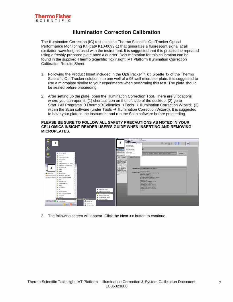
2. After setting up the plate, open the Illumination Correction Tool. There are 3 locations
where you can open it: (1) shortcut icon on the left side of the desktop; (2) go to StartAll Programs ThermoCellomics Tools Illumination Correction Wizard; (3) within the Scan software (under Tools Illumination Correction Wizard). It is suggested to have your plate in the instrument and run the Scan software before proceeding.
PLEASE BE SURE TO FOLLOW ALL SAFETY PRECAUTIONS AS NOTED IN YOUR CELLOMICS INSIGHT READER USER’S GUIDE WHEN INSERTING AND REMOVING MICROPLATES.
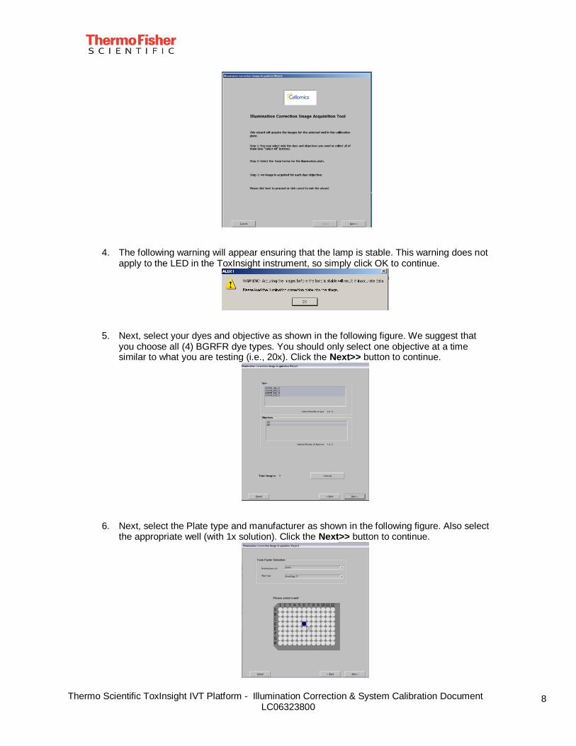
3. The following screen will appear. Click the Next >> button to continue.
1
2
3
Thermo Scientific ToxInsight IVT Platform - Illumination Correction & System Calibration Document LC06323800
8
4. The following warning will appear ensuring that the lamp is stable. This warning does not apply to the LED in the ToxInsight instrument, so simply click OK to continue.
5. Next, select your dyes and objective as shown in the following figure. We suggest that you choose all (4) BGRFR dye types. You should only select one objective at a time similar to what you are testing (i.e., 20x). Click the Next>> button to continue.
6. Next, select the Plate type and manufacturer as shown in the following figure. Also select the appropriate well (with 1x solution). Click the Next>> button to continue.
Thermo Scientific ToxInsight IVT Platform - Illumination Correction & System Calibration Document LC06323800
9
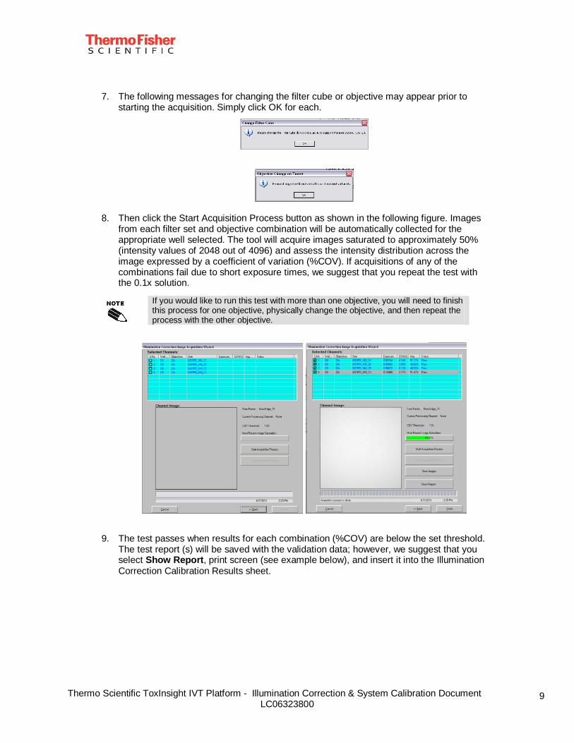
7. The following messages for changing the filter cube or objective may appear prior to starting the acquisition. Simply click OK for each.
8. Then click the Start Acquisition Process button as shown in the following figure. Images
from each filter set and objective combination will be automatically collected for the appropriate well selected. The tool will acquire images saturated to approximately 50% (intensity values of 2048 out of 4096) and assess the intensity distribution across the image expressed by a coefficient of variation (%COV). If acquisitions of any of the combinations fail due to short exposure times, we suggest that you repeat the test with the 0.1x solution.
If you would like to run this test with more than one objective, you will need to finish this process for one objective, physically change the objective, and then repeat the process with the other objective.
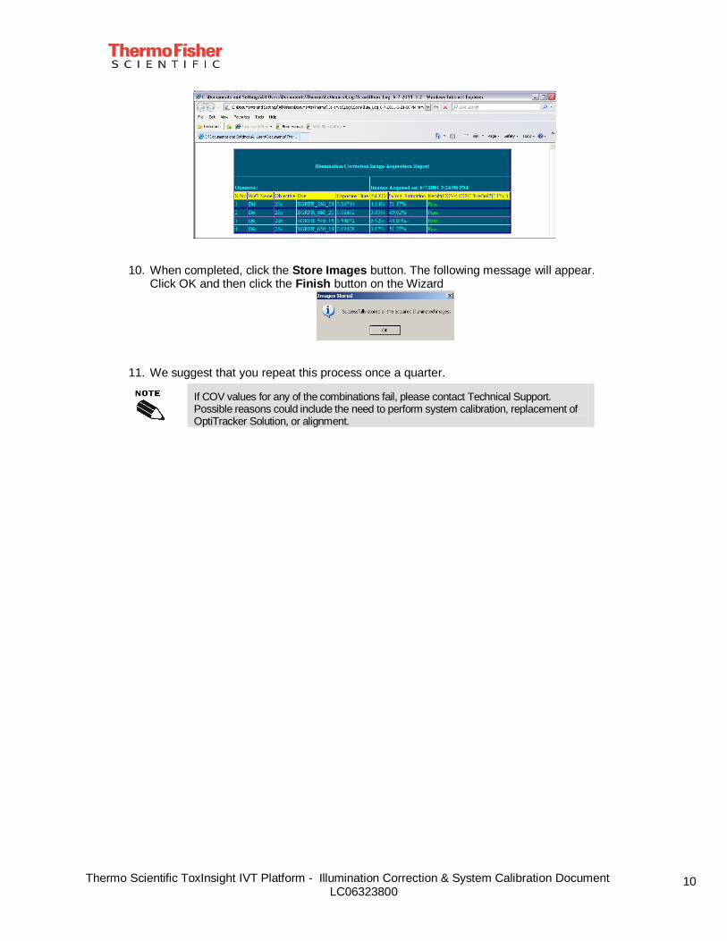
9. The test passes when results for each combination (%COV) are below the set threshold. The test report (s) will be saved with the validation data; however, we suggest that you select Show Report, print screen (see example below), and insert it into the Illumination Correction Calibration Results sheet.
Thermo Scientific ToxInsight IVT Platform - Illumination Correction & System Calibration Document LC06323800
10
10. When completed, click the Store Images button. The following message will appear. Click OK and then click the Finish button on the Wizard
11. We suggest that you repeat this process once a quarter.
If COV values for any of the combinations fail, please contact Technical Support. Possible reasons could include the need to perform system calibration, replacement of OptiTracker Solution, or alignment.
Thermo Scientific ToxInsight IVT Platform - Illumination Correction & System Calibration Document LC06323800
11
System Calibration Instructions For a routine check on the instrument’s system calibration, we suggest that you follow the procedure below, repeating this process once a month. If you would like to document each calibration, we suggest that you use the supplied Thermo Scientific ToxInsight IVT Platform System Calibration Results Sheet.
Only one objective can be installed at any time (using the Objective Change Wizard). Care must be taken when adding/removing the objective (leaving the O-ring intact) and to ensure that the stage is not bumped. If you are constantly changing objectives, we highly suggest that you check the system calibration with the proper objective prior to use. It is not necessary to calibrate the system with both objectives. Normally, the 10x objective should give you a more visible window of the well for optical alignment.
1. Obtain the provided calibrated Nunc™ Edge 96 well paint plate.
2. Ensure that both ToxInsight IVT Platform and computer are ON. PLEASE BE SURE TO FOLLOW ALL SAFETY PRECAUTIONS AS NOTED IN YOUR CELLOMICS INSIGHT READER USER’S GUIDE.
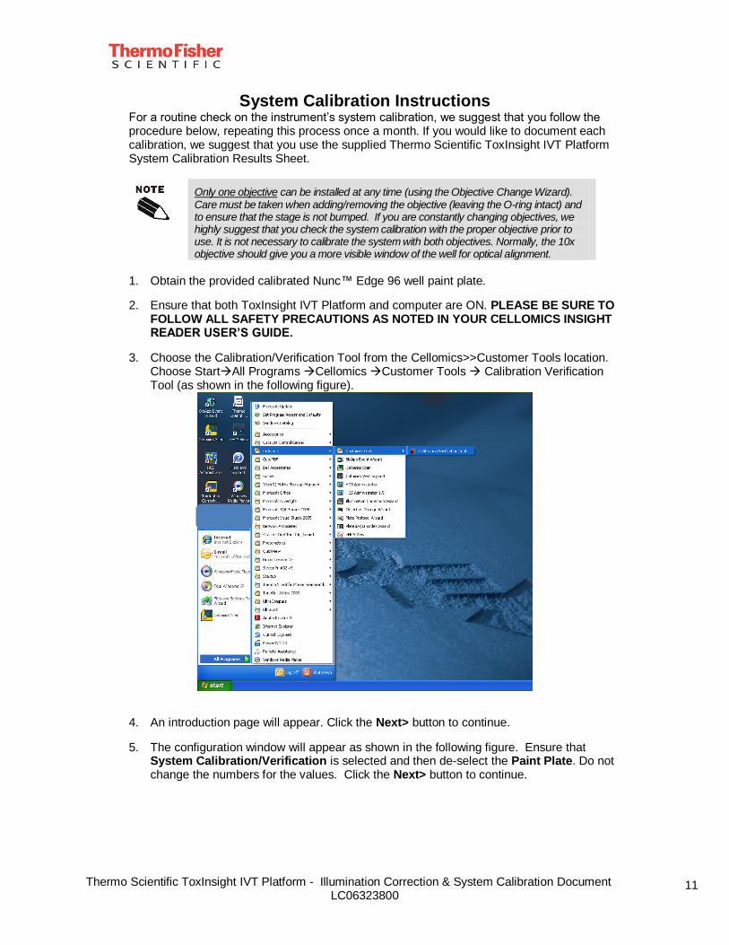
3. Choose the Calibration/Verification Tool from the Cellomics>>Customer Tools location. Choose StartAll Programs Cellomics Customer Tools Calibration Verification Tool (as shown in the following figure).
4. An introduction page will appear. Click the Next> button to continue.
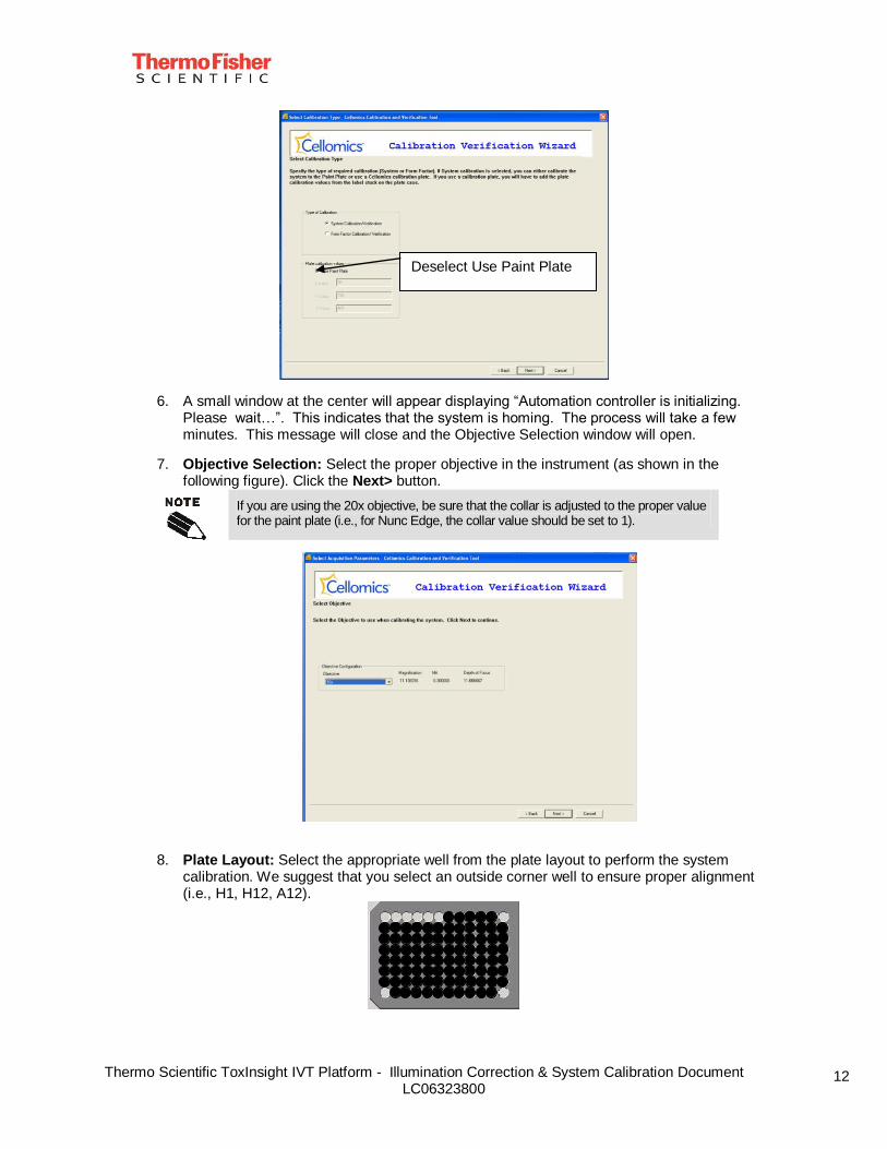
5. The configuration window will appear as shown in the following figure. Ensure that System Calibration/Verification is selected and then de-select the Paint Plate. Do not change the numbers for the values. Click the Next> button to continue.
Thermo Scientific ToxInsight IVT Platform - Illumination Correction & System Calibration Document LC06323800
12
6. A small window at the center will appear displaying “Automation controller is initializing. Please wait…”. This indicates that the system is homing. The process will take a few minutes. This message will close and the Objective Selection window will open.
7. Objective Selection: Select the proper objective in the instrument (as shown in the following figure). Click the Next> button.
If you are using the 20x objective, be sure that the collar is adjusted to the proper value for the paint plate (i.e., for Nunc Edge, the collar value should be set to 1).
8. Plate Layout: Select the appropriate well from the plate layout to perform the system calibration. We suggest that you select an outside corner well to ensure proper alignment (i.e., H1, H12, A12).
Deselect Use Paint Plate
Thermo Scientific ToxInsight IVT Platform - Illumination Correction & System Calibration Document LC06323800
13
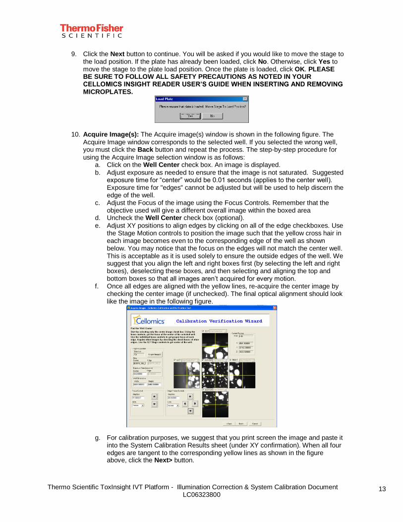
9. Click the Next button to continue. You will be asked if you would like to move the stage to the load position. If the plate has already been loaded, click No. Otherwise, click Yes to move the stage to the plate load position. Once the plate is loaded, click OK. PLEASE BE SURE TO FOLLOW ALL SAFETY PRECAUTIONS AS NOTED IN YOUR CELLOMICS INSIGHT READER USER’S GUIDE WHEN INSERTING AND REMOVING MICROPLATES.
10. Acquire Image(s): The Acquire image(s) window is shown in the following figure. The Acquire Image window corresponds to the selected well. If you selected the wrong well, you must click the Back button and repeat the process. The step-by-step procedure for using the Acquire Image selection window is as follows:
a. Click on the Well Center check box. An image is displayed. b. Adjust exposure as needed to ensure that the image is not saturated. Suggested
exposure time for “center” would be 0.01 seconds (applies to the center well). Exposure time for "edges" cannot be adjusted but will be used to help discern the edge of the well.
c. Adjust the Focus of the image using the Focus Controls. Remember that the objective used will give a different overall image within the boxed area
d. Uncheck the Well Center check box (optional). e. Adjust XY positions to align edges by clicking on all of the edge checkboxes. Use
the Stage Motion controls to position the image such that the yellow cross hair in each image becomes even to the corresponding edge of the well as shown below. You may notice that the focus on the edges will not match the center well. This is acceptable as it is used solely to ensure the outside edges of the well. We suggest that you align the left and right boxes first (by selecting the left and right boxes), deselecting these boxes, and then selecting and aligning the top and bottom boxes so that all images aren’t acquired for every motion.
f. Once all edges are aligned with the yellow lines, re-acquire the center image by checking the center image (if unchecked). The final optical alignment should look like the image in the following figure.
g. For calibration purposes, we suggest that you print screen the image and paste it into the System Calibration Results sheet (under XY confirmation). When all four edges are tangent to the corresponding yellow lines as shown in the figure above, click the Next> button.
Thermo Scientific ToxInsight IVT Platform - Illumination Correction & System Calibration Document LC06323800
14
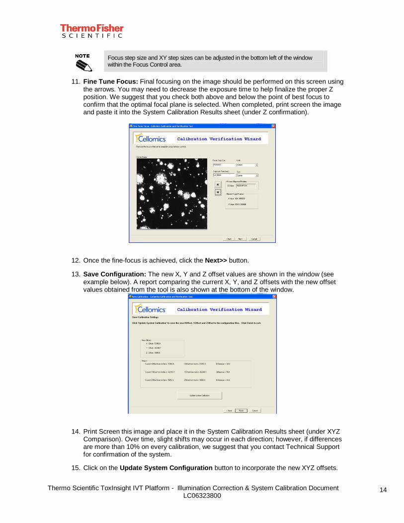
Focus step size and XY step sizes can be adjusted in the bottom left of the window within the Focus Control area.
11. Fine Tune Focus: Final focusing on the image should be performed on this screen using the arrows. You may need to decrease the exposure time to help finalize the proper Z position. We suggest that you check both above and below the point of best focus to confirm that the optimal focal plane is selected. When completed, print screen the image and paste it into the System Calibration Results sheet (under Z confirmation).
12. Once the fine-focus is achieved, click the Next>> button.
13. Save Configuration: The new X, Y and Z offset values are shown in the window (see example below). A report comparing the current X, Y, and Z offsets with the new offset values obtained from the tool is also shown at the bottom of the window.
14. Print Screen this image and place it in the System Calibration Results sheet (under XYZ Comparison). Over time, slight shifts may occur in each direction; however, if differences are more than 10% on every calibration, we suggest that you contact Technical Support for confirmation of the system.
15. Click on the Update System Configuration button to incorporate the new XYZ offsets.
Thermo Scientific ToxInsight IVT Platform - Illumination Correction & System Calibration Document LC06323800
15
16. A confirmation message box will appear for storing the calibrated offset values. Click OK.
17. Click the Finish button to close the application.
The Cancel button can be selected at any time to cancel the whole process.
US Office
Thermo Fisher ScientificLife Science ResearchBiosciences Division100 Technology DrivePittsburghPA 15219USA
Tel: 1.412.770.2200Fax: 1.412.770.2450Email: [email protected]: www.thermoscientific.com/cellomics
European Office
Thermo Fisher ScientificIndustriezone IIIIndustrielaan 279320 ErembodegemBelgium
Tel: +32 (0)53 85 71 82Fax: +32 (0)53 85 72 28Email: [email protected]: www.thermoscientific.com/cellomics