thermo scientific smart-vue.pdf · thermo scientific smart-vue software user manual 316266h0...
TRANSCRIPT
Thermo Scientific
Smart-VueSoftware User Manual
316266H09 January 2011

© 2011 Thermo Fisher Scientific Inc. All rights reserved.
Disclaimer and limitation of liability
Thermo Fisher Scientific assumes no responsibility for any loss or claims by third parties which may arise through the use of this manual and the information contained herein. This document is non-contractual and subject to change without notice.
Thermo Fisher Scientific’s liability is subject to its standard terms and conditions of sale.
Do not open the product casing and do not disassemble or modify internal components in any manner whatsoever. Thermo Scientific products do not contain any internal components that require user intervention or repair. If the product or device shows signs of improper operation, disconnect it immediately from its power source and contact Thermo Scientific technical services so that the device can be examined under proper conditions.
Release history:
Initial release January 2011

Table of Contents
Table of Contents
Chapter 1 Notices ................................................................................... 1-1
Chapter 2 Getting Started..................................................................... 2-6The Smart-Vue monitoring solution ...................................... 2-6About this manual .................................................................. 2-7Connecting to Smart-Vue Client............................................ 2-7Registering your software.................................................... 2-10
Chapter 3 Managing Users.................................................................. 3-14Adding a user .............................................................................3-15First-time connection to the application .............................. 3-19Viewing and changing an existing profile ........................... 3-21Disabling a user account ...................................................... 3-22Managing departments......................................................... 3-23
Chapter 4 Configuring and managing end-point modules / sensors4-25Adding an end-point module using SDP ............................. 4-25Adding an end-point module manually ............................... 4-28Replacing an end-point module ........................................... 4-34Changing sensor(s) on an end-point module ....................... 4-36Changing an end-point module’s battery............................. 4-38Adding a receiver................................................................. 4-40Synchronizing all end-point modules .................................. 4-41Managing the tree structure ................................................. 4-42Configuring sensors ............................................................. 4-43Enabling/Disabling sensors.................................................. 4-45Adding a measurement unit ................................................. 4-46Automatic end-point module reconnection via SDP ........... 4-48Using correction parameters ................................................ 4-49Altitude settings (for CO2 sensors only) ............................. 4-51
Chapter 5 Displaying sensors and measurements............................. 5-52Viewing sensor settings ....................................................... 5-52Displaying sensors on the main screen ................................ 5-53Using floor plans.................................................................. 5-58Collecting readings with Smart-Vue Client......................... 5-62Viewing individual sensor graphs........................................ 5-65Viewing multiple sensor graphs .......................................... 5-68Displaying sensor readings .................................................. 5-71
Smart-Vue Software User Manual 5

Table of Contents
Displaying sensor settings ................................................... 5-72
Chapter 6 Configuring and managing alarms ................................. 6-75Configuring alarms .............................................................. 6-75Enabling and setting limits .................................................. 6-76Acknowledging alarms ....................................................... 6-79Looking up alarm lists ......................................................... 6-83
Chapter 7 Configuring and testing alerts .......................................... 7-85Managing call groups........................................................... 7-85Configuring alerts for groups and receivers ........................ 7-87Adding the wireless siren to your system ............................ 7-90Configuring local alerts ....................................................... 7-92Configuring periods without alerts ...................................... 7-93Stopping an audio or visual alert device.............................. 7-95Running a test alarm ............................................................ 7-96Configuring alert system settings ........................................ 7-98
Chapter 8 Testing system status ....................................................... 8-100Testing wireless performance ............................................ 8-100Testing battery counters..................................................... 8-102Testing sensor data-logging status ..................................... 8-103
Chapter 9 Archiving data.................................................................. 9-104Selecting the archive period............................................... 9-104Displaying archived data ................................................... 9-106
Chapter 10 Printing and exporting reports..................................... 10-108Sensor report .................................................................... 10-108Alarm report..................................................................... 10-111Settings report .................................................................. 10-111Adding a custom logo to your reports ............................. 10-113
Chapter 11 Viewing the event log..................................................... 11-114Viewing the event log ...................................................... 11-114
Chapter 12 Configuring and personalizing the application........... 12-116Choosing a visual theme .................................................. 12-116Displaying graphs full-screen .......................................... 12-117Disabling the recent software events screen .................... 12-117
6 Smart-Vue Software User Manual

Table of Contents
Disabling settings protection ........................................... 12-118Enabling the 21 CFR Part 11 option................................ 12-119Advanced maintenance options ....................................... 12-120Opening the user manual ................................................. 12-123Automatically updating the user manual ......................... 12-123Contact Information......................................................... 12-124Warranty Statement ......................................................... 12-125
Smart-Vue Software User Manual 7

Notices
Chapter 1 Notices
Safety instructions IMPORTANT NOTE: Do not use this product for protection or as part of an automated emergency system or for any other application that involves protecting people and/or property. Customers and users of Thermo Scientific products are responsible for making sure that the product is fit for the intended usage. Do not open the product casing and do not disassemble or modify internal components in any manner. Thermo Scientific products do not contain any internal components that require user intervention or repair. If the device shows signs of improper operation, disconnect it immediately from its power source and contact Thermo Fisher Scientific technical services.
Electrical warning (fordevices with AC adapter)
When using a Smart-VueTM product with an AC adapter (100-240V AC – 12V, 6V or 5V DC), always use the specific adapter provided by your supplier (same brand, same product reference). Do not open the adapter yourself and do not dismantle internal components or modify them in any manner. The adapter does not contain any user-reparable parts. If the adapter shows any sign of malfunction, unplug it immediately and contact Thermo Fisher Scientific for repair or replacement. Do not connect the adapter to a device or peripheral other than the Smart-Vue product for which it was intended. Unplug the power cable from the electrical outlet when the adapter is not in use. Do not cause a short-circuit with the electrical plug. Do not force either the AC or DC plug. Before removing the connector from any Smart-Vue hardware devices or unplugging power cables, first unplug the cable from the power outlet. Do not subject the adapter to physical shock, which could cause serious malfunction or damage. Do not use or place the adapter in a wet or humid location. This adapter is not waterproof.
Thermo Fisher Scientific Smart-Vue Software User Manual 1

Notices
Battery warningSome Smart-Vue products contain a lithium battery. Make sure you observe polarity (+/-) when inserting batteries into Smart-Vue devices. Reversing polarity by inserting the batteries incorrectly can cause the product to heat up and may lead to a battery liquid leak. Use only batteries recommended by Thermo Fisher Scientific. Do not change battery types, such as alkaline and magnesium, or use batteries of different brands or even different types of batteries of the same brand. Incorrect batteries may cause the device to heat up, and may result in a fire or battery liquid leakage. Never dispose of batteries in a fire. Do not charge regular batteries that are not specifically rechargeable. When batteries are low, or if the battery-operated device in question remains unused for a long period of time, remove the batteries from the device to avoid any risk of battery liquid leakage. Never leave batteries within reach of children. In case of a battery leak, avoid all contact with the liquid present on the batteries. Rinse with clear water immediately if the battery liquid comes into contact with the eyes, mouth or skin. Contact a doctor or emergency service immediately. Battery liquid is corrosive and can damage vision, or cause blindness or chemical burns.
Serial and TCP/IPNetwork Receivers
Do not disconnect the serial receiver from your PC or the IP receiver from its connection to your intranet system. Disconnection will prevent the transmission of data (including alarms) from the end-point modules.
Loss of power to the receiver will also prevent the transmission of data (including alarms) from the end-point modules. Ensure the receiver is plugged into an Uninterruptable Power Supply (UPS) at all times.
USB receivers All Smart-Vue USB products and drivers are tested thoroughly. However, it is not possible to test and qualify all computers and configurations. Our experience has shown there are some variations in USB implementations by computer manufacturers. It is therefore important for users to avoid unnecessary risk by testing the products and validating processes internally to ensure stability and reliability of USB communications in their environment.
User precautions Here is a non-exhaustive list of known issues that may affect the Smart-Vue USB receiver. Please consider these and other risks when qualifying your system.
USB plugs cannot be physically secured to USB ports. Ensure that your USB cable is fastened and routed so it will not be accidentally unplugged.
2 Smart-Vue Software User Manual Thermo Fisher Scientific

Notices
If your USB receiver is physically disconnected from the USB port on your computer after configuration, it is imperative to plug it back into the same port. Otherwise, the system may not recognize the receiver and communication with the receiver could be lost.
Do not unplug the USB receiver, even temporarily, to attach another peripheral USB device such as a camera, printer, MP3 player, etc. The new device may update the USB drivers on your computer and cause the system to not recognize the receiver when it is returned to the previously configured port.
Deactivate energy saving settings (USB installation only). Power management settings on your computer may shut down power to the USB port and disrupt communication to the USB receiver after a period of non-use to conserve energy. Speak to your local IT department about reconfiguring your system’s power management settings so your computer will not “sleep” and disrupt communication during installation.
FCC statement This paragraph pertains to 915 MHz Smart-Vue wireless modules.This device complies with part 15 of the FCC rules. Operation is subject to the following two conditions: (1) This device may not cause harmful interference, and (2) this device must accept any interference received, including interference that may cause undesired operation: FCC Part 15 §107 - §109 - §207 - §247 (Ed 2008).
Conformity withEuropean regulations
This paragraph pertains to 868 MHz Smart-Vue wireless modules. The CE mark on this the product indicates that Thermo Fisher Scientific declares that this product is compliant with Radio equipment and Telecommunications Terminal equipment (R&TTE) directive 1999/5/EC and the Low Voltage Directive (LVD) 2006/95/EC. The following standards were utilized to meet the essential requirements of these directives: EN 301 489-3 v1.4.1 (02), EN 300 220-2 V2.1.2 (R&TTE) & EN 60950-1:2006/A11:2009 (LVD).
The most current EC Declaration of Conformity may be downloaded from the Smart-Vue World Wide Web at:
www.thermoscientific.com/smart-vue
CAUTION : Any changes or modifications not expressly approved by Thermo Fisher Scientific could void the user's authority to operate the equipment.
Thermo Fisher Scientific Smart-Vue Software User Manual 3

Notices
WEEE compliance This wireless device complies with the essential requirements and other relevant provisions of the Waste Electrical and Electronic Equipment Directive 2002/96/EC (WEEE Directive).
Environmentalprotection
Please respect local regulations concerning disposal of packaging, unused wireless devices and their accessories, and promote their recycling.
RoHS compliance The wireless device is in compliance with the restriction of the use of certain hazardous substances in electrical and electronic equipment Directive 2002/95/EC
(RoHS Directive). Do not dispose of this product with household trash. Thermo Fisher Scientific recycles this product under certain conditions. Please contact us for more information.
General requirementsand recommendations
• The personal computer (PC) hosting Smart-Vue Server software runs continuously, 24/7/365, and should be connected to an Uninterruptible Power Supply (UPS) that protects against power surges and provides power to back up the PC and components.
• All Smart-Vue products using an AC adapter should also be plugged into a UPS.
• A UPS is also recommended as a power backup for your communication/network systems.
• Weekly manual system testing (e.g., disconnect a sensor from its end-point module, verify the communications system is working) should be should be performed as defined in your Standard Operating Procedure (SOP).
• Recommended maintenance and calibration procedures should be followed.
• If you are storing cold products, Thermo Fisher Scientific recommends use of a back-up cooling system (e.g., CO2 or LN2) to maintain freezer chamber temperature below the critical level should a power failure occur. Contact your local sales representative for more information.
4 Smart-Vue Software User Manual Thermo Fisher Scientific

Notices
• Thermo Fisher Scientific recommends Installation and Operational Qualifications (IQ/OQ) be performed before initial use.
• For timely notification of an emergency/alarm, it is critical to establish primary, secondary and tertiary call-out procedures with escalation so contact is not dependent on reaching one individual. Ideally, ultimate contact is with a security department or company with 24/7 monitoring.
Note: End-point modules shall not be placed in environmental conditions beyond recommended specifications.
Thermo Fisher Scientific Smart-Vue Software User Manual 5
Getting StartedThe Smart-Vue monitoring solution
Chapter 2 Getting Started
The Smart-Vuemonitoring solution
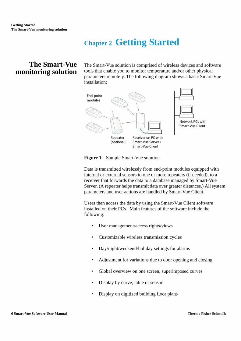
The Smart-Vue solution is comprised of wireless devices and software tools that enable you to monitor temperature and/or other physical parameters remotely. The following diagram shows a basic Smart-Vue installation:
Figure 1. Sample Smart-Vue solution
Data is transmitted wirelessly from end-point modules equipped with internal or external sensors to one or more repeaters (if needed), to a receiver that forwards the data to a database managed by Smart-Vue Server. (A repeater helps transmit data over greater distances.) All system parameters and user actions are handled by Smart-Vue Client.
Users then access the data by using the Smart-Vue Client software installed on their PCs. Main features of the software include the following:
• User management/access rights/views
• Customizable wireless transmission cycles
• Day/night/weekend/holiday settings for alarms
• Adjustment for variations due to door opening and closing
• Global overview on one screen, superimposed curves
• Display by curve, table or sensor
• Display on digitized building floor plans
6 Smart-Vue Software User Manual Thermo Fisher Scientific

Getting StartedAbout this manual
• Client-server architecture with remote look-up via network and Internet
• Centralized SQL Database (complies with FDA Title 21 CFR Part 11)
• Password protection (complies with FDA Title 21 CFR Part 11)
• Audit trail (complies with FDA Title 21 CFR Part 11)
About this manual This user manual describes the many features of the Smart-Vue Client application. It does not cover installation. Software installation and initial receiver setup are completed simultaneously. Refer to your latest Thermo Scientific Smart-Vue Server/Client USB – Serial Wireless Receiver Installation Guide for system requirements and installation instructions. Separate installation guides for receivers, repeaters, end-point modules and sirens are on the CD-ROM included with your purchase.
This manual focuses on the fields on screens you will encounter. It does not necessarily indicate each time you may be prompted to log in (e.g., when you choose a particular function, such as Sensor Settings) or need to click on OK or Yes to accept your entries or changes.
Connecting toSmart-Vue Client
As with most client-server applications, you must log in before you can use the software. An authentication screen opens when you double-click the Smart-Vue Client icon on your PC’s desktop. Enter your Login and Password, which should already be configured in the system (for information on creating user accounts, see Chapter 3 – Managing Users).
Figure 2. Authentication (login) screen
As a security measure, your account will be locked if you enter an incorrect password into the login/password window three consecutive times. If this occurs, please contact your system administrator.
Thermo Fisher Scientific Smart-Vue Software User Manual 7

Getting StartedConnecting to Smart-Vue Client
Smart-Vue Client connects to the Smart-Vue Server application running on a local or remote server. By clicking on >> you may enter the server name or IP address, as well as the port to use (if other than the default value).
Figure 3. Authentication (login) screen with server connection options
Note: When you first run Smart-Vue Client, the application’s default values are set to connect to the Smart-Vue Server database by running on your computer directly (local host) using the communication port 1090.
Click on OK to login to the application. You will receive an error if Smart-Vue Client is unable to communicate with Smart-Vue Server with the name and/or port number you provided.
The Smart-Vue Client welcome page is displayed if connection is successful and your login information is accepted by the system. The time it takes to load the application depends on the number of measurement points to display, as well as the speed, the bandwidth of the network and the processing power of the computer being used.
8 Smart-Vue Software User Manual Thermo Fisher Scientific

Getting StartedConnecting to Smart-Vue Client
Figure 4. Smart-Vue welcome screen
Figure 5 shows the main Smart-Vue screen, with some sample sensors configured. The tree structure on the left shows the hierarchy of sensors and receivers. Sensor readings are shown on the right. These topics are covered in detail in this manual.
Thermo Fisher Scientific Smart-Vue Software User Manual 9

Getting StartedRegistering your software
Figure 5. Main Smart-Vue screen
Registering yoursoftware
As you begin using Smart-Vue Client, you will be prompted to register the software.
Note: It is important to register your software to benefit from technical support and product updates.
Obtaining yourregistration key
A unique serial number is provided on your Smart-Vue software CD-ROM jewel case. You will need to provide this serial number in order to obtain a registration key, and then enter the information into the software to register the product.
The following pop-up appears periodically until you register your software. It contains a link to the registration process on the Thermo Scientific Web site. If you have an Internet connection, you may click on the link in the pop-up to register. At the end of the registration process, your registration key will be sent to you via e-mail.
Figure 6. Periodic software registration reminder
10 Smart-Vue Software User Manual Thermo Fisher Scientific

Getting StartedRegistering your software
Alternatively, you may access the registration link from within Smart-Vue Client at any time by doing the following:
1. Click on Help ==> (Register Software).
Figure 7. Software registration screen
2. Click on How to get my registration key?
3. If your Smart-Vue Client computer is connected to the Internet, the link opens the registration process on the Thermo Scientific Web site in your default browser. At the end of the registration process, your registration key will be sent to you via e-mail.
Thermo Fisher Scientific Smart-Vue Software User Manual 11

Getting StartedRegistering your software
4. If you do not have Internet access from your Smart-Vue Client computer, the Software registration screen expands with an explanation of how to proceed
Figure 8. Software registration screen
• Connect to the Internet and go to http://www.thermoscientific.com/smart-vueregister . Follow the instructions on your screen.
• Send an e-mail with a subject of “Smart-Vue Registration”. Include in the body of the e-mail your company name, your name, your e-mail address, and your software serial number and version. Please send e-mail to http://www.thermoscientific.com/smart-vue.
• Additional contact information is provided in the Help ==> About screen of your Smart-Vue Client software.
5. Your registration key will be returned to you by e-mail as quickly as possible. Response time is dependent on normal business hours.
12 Smart-Vue Software User Manual Thermo Fisher Scientific

Getting StartedRegistering your software
Entering yourregistration key
1. Once you have received your registration key by e-mail, click on Help ==> (Registered software)
2. Fill in the fields shown in Figure 7 and then click on OK. Your software serial number is provided on your Smart-Vue software CD-ROM jewel case.
Thermo Fisher Scientific Smart-Vue Software User Manual 13

Managing UsersRegistering your software
Chapter 3 Managing Users
Smart-Vue Client offers a complete user management interface. Users with Super Administrator or Administrator rights can use this interface to create and maintain individualized profiles for each person who uses the application or handles alerts.
1. Click on Settings ==> ( User and call group management).
If you are connecting to the system with View and Acknowledge or View rights, you will be automatically redirected to your user form. Only Super Administrators or Administrators have access to the screen shown below:
Figure 9. Sample user management screen
14 Smart-Vue Software User Manual Thermo Fisher Scientific

Managing UsersAdding a user
Adding a user 1. In the User management screen, click on Create user to open a new user identification form.
2. On the Identity tab, enter the user’s Last name and First name, choose a department from the pull-down menu, and enter a Login name to use when connecting to the software. If this is a new installation you must create one or more departments to reflect your organizational structure.
Figure 10. Filling in user details
Note: You may not change the login name for an existing user, but all other existing user information may be edited at any time.
3. Assign the user’s role by choosing one of the following options
Figure 11. Assigning user roles
• Super Administrator has access to all application features.
• Administrator has access to all application features, except those used to assign sensor viewing (see Chapter 4 – Configuring and Managing End-Point Modules/Sensors). Administrators are not authorized to archive data.
• Users with View and Acknowledge rights can handle alarms issued by the system for the sensors they monitor but do not have access to any setup/configuration screens.
Thermo Fisher Scientific Smart-Vue Software User Manual 15

Managing UsersAdding a user
• Users with Viewing rights are not allowed to handle alarms issued by the system for the sensors they monitor and do not have access to any setup screens.
Note: Only Super Administrators can assign Super Administrator rights for other users.
4. Define the alert types that are sent to the user in question.
Alarm limit alerts represent high and low limits values that you may configure for sensor reading
Technical alerts are related to technical issues concerning your sensors and receivers, such as low battery and communication errors. Here you may choose to receive either type of alert or all alerts:
Figure 12. Determining alerts for a user
5. Fill in complete Contact details as required. The Contact details section shown in figure 13 serves two purposes:
- It provides a space in which you may store various contact information regarding the user.
- It lets you define how that person may be contacted to handle relevant alerts
Note: Use the checkboxes at the top of the Contact details screen to enable or disable the use of telephone, fax and e-mail alerts for the user. For telephone alerts, you may enter one number in each of the two fields per time slot. These numbers will be called one after the other.
16 Smart-Vue Software User Manual Thermo Fisher Scientific

Managing UsersAdding a user
If you wish to have e-mail alerts sent to multiple e-mail addresses, enter the addresses into the e-mail address fields separated by a semi-colon”;”
Figure 13. User contact details
Here you may enter numbers for the various alert types: telephone (up to 2 numbers for each time-slot), and fax, as well as e-mail addresses. Fields are available for daytime, night-time and weekend time-slots for each option.
Note: If you must dial a prefix to reach an outside line, don't forget to include it when entering the user's telephone and fax numbers.
6. Click on the Password tab to enter and confirm an initial password for the user. Passwords are not case-sensitive and must contain at least six characters. The user must change this password when connecting to the application for the first time.
By default, accounts are set to expire after one year. You may change this value to meet your needs. Click on the Expiration
Thermo Fisher Scientific Smart-Vue Software User Manual 17

Managing UsersAdding a user
date drop-down menu and choose a month, day and year from the date selection calendar.
Figure 14. Setting user password
The Active user checkbox is enabled when you create a new user. If you un-check this checkbox, the user cannot access the application.
18 Smart-Vue Software User Manual Thermo Fisher Scientific

Managing UsersFirst-time connection to the application
First-timeconnection to the
application
The first time you connect to the application with your account, you are prompted to change the initial password:
Figure 15. Changing a password upon first connection
1. Enter your initial password.
2. Enter a new password.
3. Confirm the new password by re-typing it in the bottom field.
4. Click on OK when done.
Note: If your password is due to expire within the next thirty days, the first time you log in during this period the software will prompt you to change your password. This will reset the expiration counter for one year.
Super Administrators orAdministrators
When a Super Administrator or Administrator opens the User Management screen, all current user accounts are automatically displayed in a table on the screen. You may use the fields and the Search button in the Filters section to refine the user list according to specific criteria:
Figure 16. User search filter options
Double-click on a user name in the table to open that person’s profile.
Thermo Fisher Scientific Smart-Vue Software User Manual 19

Managing UsersFirst-time connection to the application
Figure 17. Editing user profile
You may not change the login name for an existing user. All other information on this form may be edited.
20 Smart-Vue Software User Manual Thermo Fisher Scientific

Managing UsersViewing and changing an existing profile
Viewing andchanging an existing
profile
Users with “View and Acknowledge” and “View” user level
Remember, if you connect to the application with the “View and Acknowledge” or “View” user level, clicking on the Call Group and User Management icon ( ) on the main screen opens your user profile settings directly.
In that case, since you do not have administrator rights, you may only change your own contact information (phone, mobile and fax numbers and e-mail address) and your password:
Figure 18. User profile opened by a user who only has “Viewing” rights
Areas that you do not have the right to change are grayed out.
Note: To access your profile (the currently logged-in user) directly, you may click on View my profile in the lefthand menu of the user management main screen.
Thermo Fisher Scientific Smart-Vue Software User Manual 21

Managing UsersDisabling a user account
Disabling a useraccount
While it is not technically possible to delete users from the system (for long-term traceability purposes), a user with Super Administrator or Administrator rights can disable existing accounts. If you open a user profile while connected with these rights, go to the Password tab and un-check the Active user checkbox:
Figure 19. Disabling an account by changing the “Active user” status
22 Smart-Vue Software User Manual Thermo Fisher Scientific

Managing UsersManaging departments
Managingdepartments
Departments may be used to organize the user database to, among other things, make it easier to select members when creating Call Groups (see Chapter 7 – Configuring and Testing Alerts). Follow these steps to add a new department:
1. In the main screen, click on Settings ==> (User and call group management).
2. Click on Department list in the lower left-hand panel.
3. Click on Create department in the upper left-hand panel. Enter the department name in the dialog box and click on OK. The new department is automatically added to the list..
Figure 20. Editing the department list
Note: A default department called System Admin is automatically created in the database when you install Smart-Vue. You may decide to keep this entry or delete it. In any case, at least one department must exist in the system for you to be able to create users.
4. Logged in as Super Administrator or Administrator, click on Department list in the left-hand pane of the User Management screen (#1 in Figure 21) to open the list of currently configured departments, as shown below.
Thermo Fisher Scientific Smart-Vue Software User Manual 23

Managing UsersManaging departments
5. Click on a department name to display its members in the right-hand pane.
Figure 21. Displaying departments and their members
6. Double-click on a user’s name under Members (#2) to open his or her current profile.
7. You may delete a department by clicking on Remove (#3) as long as that department does not contain any members.
1
3
2
24 Smart-Vue Software User Manual Thermo Fisher Scientific

Configuring and managing end-point modules / sensorsAdding an end-point module using SDP
Chapter 4 Configuring and managing end-point modules / sensors
The features described in this section are reserved for Super Administrators or Administrators.
Note: Smart-Vue Client supports automatic end-point module configuration using a Service Discovery Protocol (SDP). This feature automates the installation of Smart-Vue end-point modules into the system. We recommend using this installation method for networks with up to 15 end-point modules. For systems larger than 15 end-point modules, we recommend that you perform manual installation (as described in the next section “Adding an end-point module manually”.
Adding an end-pointmodule using SDP
In Smart-Vue Client, go to the main screen so you can see the dashboard display (see Chapter 5- Displaying Sensors and Measurements). Then, on the Smart-Vue end-point module that you wish to install, press the button for three seconds (#1 in Figure 22). The LCD displays the message “Searching” (#2).
Figure 22. Press the button for three seconds to initiate connection process
1
32
Thermo Fisher Scientific Smart-Vue Software User Manual 25

Configuring and managing end-point modules / sensorsAdding an end-point module using SDP
During this process, the Smart-Vue end-point module automatically detects your Smart-Vue Server system and adds itself as an un-configured end-point module. When the end-point module connects, the message “Connected” is displayed on its LCD screen, along with a signal strength indicator showing the quality of the signal with the connected receiver (#3).
End-point modules added in this manner are added immediately to Smart-Vue Client, where you can see them in the Tree Structure (left-hand panel), in a default SDP group (#4 in figure 23).
Figure 23. New end-point module added to receiver’s default “SDP” group
Using the SDP feature to add end-point modules ensures that each end-point module benefits from an optimal wireless connection to the receiver, using already-configured end-point modules as repeaters to relay the wireless signal if necessary.
4
26 Smart-Vue Software User Manual Thermo Fisher Scientific

Configuring and managing end-point modules / sensorsAdding an end-point module using SDP
Note: End-point modules/sensors added to the system via SDP are automatically visible to all Super Administrators or Administrators. The clocks in these end-point modules are synchronized with the Smart-Vue Server clock.
Smart-Vue Client settings windows do not refresh automatically if they are open when you add an end-point module using SDP. If one of the settings windows is open (such as F11) when you add a new end-point module, the new module will be displayed in the tree structure and dashboard when you close that window. Press F11 again to adjust the settings for the new sensor.
Thermo Fisher Scientific Smart-Vue Software User Manual 27

Configuring and managing end-point modules / sensorsAdding an end-point module manually
Adding an end-pointmodule manually
Follow these steps to add a Smart-Vue end-point module to the system manually:
1. Click on Settings ==> (Sensor settings) or press F11, to open the sensor settings screen.
Figure 24. Sensor settings window main menu (F11 from main screen)
2. Click on Add / Update a module in the main menu bar or press F11 again to open the Add/Update wireless modules screen:
Figure 25. Adding and updating an end-point module
28 Smart-Vue Software User Manual Thermo Fisher Scientific

Configuring and managing end-point modules / sensorsAdding an end-point module manually
Adding a new end-point module involves the following seven steps:
1. Testing wireless communications
- If the end-point module you wish to add is not shown in the list on the left, choose a receiver from the drop-down menu (#1 in Figure 26) in the wireless test section shown below:
Figure 26. Adding an end-point module manually
- Use the up/down arrows (#2) to specify the number of repeaters (if any) you are using to reach the end-point module in question
- Enter repeater serial numbers (if any) in the repeater fields (#3).
- Enter the end-point module’s serial number (#4).
- Click on Power (#5).
The results of communication tests between the receiver, repeaters and the end-point module are displayed as percentages in the blue boxes, as shown in the example below (which uses one repeater to reach the end-point module).
Figure 27. Preliminary test of end-point module’s wireless connection
Note: A wireless performance test in the Smart-Vue application is acceptable if the displayed percentages are 30% or higher. Below this level, communication with the end-point module runs the risk of being altered, with serious impact on collecting stored measurements and triggering alarms; moving endpoint modules or a repeater may be required to boost signal strength.
3 33 41
5
2
Thermo Fisher Scientific Smart-Vue Software User Manual 29
Configuring and managing end-point modules / sensorsAdding an end-point module manually
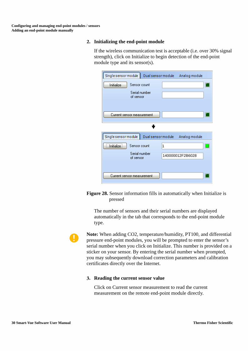
2. Initializing the end-point module
If the wireless communication test is acceptable (i.e. over 30% signal strength), click on Initialize to begin detection of the end-point module type and its sensor(s).
Figure 28. Sensor information fills in automatically when Initialize is pressed
The number of sensors and their serial numbers are displayed automatically in the tab that corresponds to the end-point module type.
Note: When adding CO2, temperature/humidity, PT100, and differential pressure end-point modules, you will be prompted to enter the sensor’s serial number when you click on Initialize. This number is provided on a sticker on your sensor. By entering the serial number when prompted, you may subsequently download correction parameters and calibration certificates directly over the Internet.
3. Reading the current sensor value
Click on Current sensor measurement to read the current measurement on the remote end-point module directly.
1
140000012F2B6028
30 Smart-Vue Software User Manual Thermo Fisher Scientific

Configuring and managing end-point modules / sensorsAdding an end-point module manually
4. Synchronizing the end-point module’s clock
You must click on Synchronize module clock to make sure that the end-point module’s internal clock is properly aligned with the overall system clock. You may click on Battery indicator to see the current level of battery power.
Figure 29. Updating end-point module status upon installation
Note: Once an end-point module has been added, the server will update all end-point module clocks every Sunday at 05:00 AM to maintain data logging integrity.
5. Resetting the battery counter
Note: Use the reset battery function only after installing a new, unused battery in an end-point module. Do not reset the battery counter if you did not install a new, unused battery. The “Changing an end-point module’s battery” section can be found later in this chapter.
Only if a new battery has been installed, click on Reset battery counter, and then carry out a test by clicking on Battery indicator to confirm the counter is indeed properly reset to 100%.
6. Adding the new sensor(s) to the system
Click on Add ==> Close to add the sensor(s) attached to the new end-point module to the system.
Thermo Fisher Scientific Smart-Vue Software User Manual 31

Configuring and managing end-point modules / sensorsAdding an end-point module manually
7. Adding the sensor(s) to a group
Note: If you have not configured any groups yet, click on Create a group in the main menu bar. For details on creating groups in the tree hierarchy, see the “Managing the tree structure” section later in this chapter.
Your new sensor is displayed in the Sensor settings screen like this:
Figure 30. New end-point module added, but not assigned to a group
You must move each new end-point module from the right-hand side of the tree view to one of your own groups in the tree structure on the left by dragging it with your mouse to the desired location (e.g. into to My group).
Figure 31. New end-point module moved into a group
To save your changes and update the end-point module and its sensor(s), click on Close ==> Yes ==> OK. Choose No to discard your changes, or Cancel to stay on the Sensor settings screen.
Note: In order to delete an end-point module from the Sensor settings screen and the system, you must first move it into a group before clicking on the Delete icon ( ).
32 Smart-Vue Software User Manual Thermo Fisher Scientific

Configuring and managing end-point modules / sensorsAdding an end-point module manually
Your new end-point module is now displayed in the Smart-Vue main screen like this:
Figure 32. New end-point module displayed in main screen
Thermo Fisher Scientific Smart-Vue Software User Manual 33

Configuring and managing end-point modules / sensorsReplacing an end-point module
Replacing anend-point module
Smart-Vue Client allows you to replace a given end-point module with another identical end-point module easily. This feature is completely transparent with respect to traceability, as the measurements carried out by the new end-point module simply continue from where the previous end-point module stopped in the software.
Note: You may only change end-point modules if:
- The new end-point module has not been previously installed in the system.
- The two end-point modules are of the same type.
- The two end-point modules have the same number of sensors.
To swap out an old end-point module and put a new one in its place:
1. Click on Settings ==> (Sensor settings) or press F11, to open the Sensor settings screen.
2. Click on Add / Update a module or press F11 again to go to the Add/update wireless modules screen.
34 Smart-Vue Software User Manual Thermo Fisher Scientific
Configuring and managing end-point modules / sensorsReplacing an end-point module
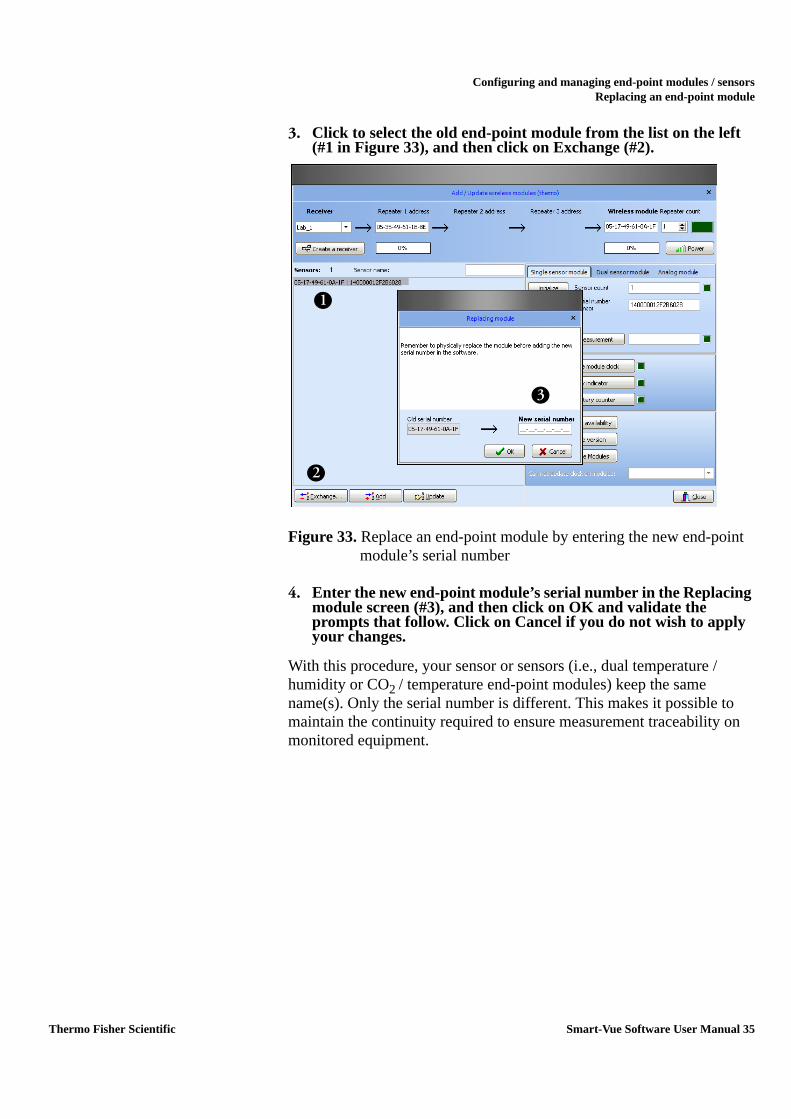
3. Click to select the old end-point module from the list on the left (#1 in Figure 33), and then click on Exchange (#2).
Figure 33. Replace an end-point module by entering the new end-point module’s serial number
4. Enter the new end-point module’s serial number in the Replacing module screen (#3), and then click on OK and validate the prompts that follow. Click on Cancel if you do not wish to apply your changes.
With this procedure, your sensor or sensors (i.e., dual temperature / humidity or CO2 / temperature end-point modules) keep the same name(s). Only the serial number is different. This makes it possible to maintain the continuity required to ensure measurement traceability on monitored equipment.
3
2
1
Thermo Fisher Scientific Smart-Vue Software User Manual 35

Configuring and managing end-point modules / sensorsChanging sensor(s) on an end-point module
Changing sensor(s)on an end-point
module
Follow these steps to change the sensor(s) attached to a given end-point module:
1. Change the sensor on your end-point module as necessary.
2. In Smart-Vue, click on Settings ==> (Sensor settings) press F11, to open the Sensor settings screen.
3. Click on Add / Update a module or press F11 again to go to the Add/update wireless modules screen.
4. In the wireless sensor list on the left-hand, select the sensor for which you have physically changed the sensor (#1 in Figure 34).
5. Then click on Initialize (#2) so the system can detect the new sensor.
Figure 34. Replace sensor on an end-point module and then click on Initialize
3
21
36 Smart-Vue Software User Manual Thermo Fisher Scientific

Configuring and managing end-point modules / sensorsChanging sensor(s) on an end-point module
The serial number is read automatically for digital temperature sensors. For analog sensors with serial numbers, you will be prompted to enter the sensor’s serial number as shown here (actual dialog window will depend on end-point module type):
Figure 35. Enter sensor serial number if prompted (for sensors other than digital temperature sensors)
6. Click on Current sensor measurement (#3) to read the sensor and test to make sure it is working correctly.
7. If the displayed value is coherent, click on Update (below the sensor list) for the system to accept this change:
Note: Don’t forget to update the A and B correction values in the Sensor settings setup screen for the sensor in question (see “Configuring sensors”) later in this chapter.
Thermo Fisher Scientific Smart-Vue Software User Manual 37

Configuring and managing end-point modules / sensorsChanging an end-point module’s battery
Changing anend-point module’s
battery
If you need to change the battery in a given end-point module, we recommend also changing the batteries in all other end-point modules connected to the same receiver at the same time.
Note: Before removing the battery in any given end-point module, make sure you download the data from the end-point module first (see “Downloading Logged Data” in the “Collecting Readings with Smart-Vue Client” section of Chapter 5). Instructions for changing batteries are included in your endpoint module’s installation guide.
Follow these steps to change the battery in an end-point module:
1. Start by replacing the battery in your end-point module.
2. In the software, click on Settings ==> (Sensor settings) or press F11, to open the Sensor settings screen.
3. Click on Add / Update a module or press F11 again to go to the Add/update wireless modules screen.
4. Select the sensor (#1 in Figure 36) for which you have changed the battery.
5. Click on Initialize (#2) and enter the sensor’s serial number if prompted.
6. Click on Current sensor measurement (#3) to read the sensor and test to make sure it is working correctly.
7. Click on Synchronize module clock (#4) to update the end-point module’s clock.
38 Smart-Vue Software User Manual Thermo Fisher Scientific
Configuring and managing end-point modules / sensorsChanging an end-point module’s battery
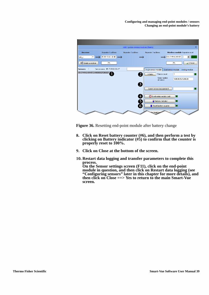
Figure 36. Resetting end-point module after battery change
8. Click on Reset battery counter (#6), and then perform a test by clicking on Battery indicator (#5) to confirm that the counter is properly reset to 100%.
9. Click on Close at the bottom of the screen.
10. Restart data logging and transfer parameters to complete this process.On the Sensor settings screen (F11), click on the end-point module in question, and then click on Restart data logging (see “Configuring sensors” later in this chapter for more details), and then click on Close ==> Yes to return to the main Smart-Vue screen.
3
21
654
Thermo Fisher Scientific Smart-Vue Software User Manual 39

Configuring and managing end-point modules / sensorsAdding a receiver
Adding a receiver Follow these steps to add a new receiver to your Smart-View system:
1. In the software, click on Settings ==> (Sensor settings) or press F11, to open the Sensor settings screen.
2. Click on Add / Update a module or press F11 again to go to the Add/update wireless modules screen.
3. Click on Create a receiver to open the New receiver connection screen.
Figure 37. New receiver configuration
4. Enter the name (maximum of 8 characters) for the new receiver (#1 in Figure 37).
5. Select transmission speed (#2) of 9600 Baud.
6. In the Connection from COM port section, please use the default setting of “localhost” in the Host field for standard installations (#3) (for advanced installations, check with your Thermo Fisher Scientific Service Representative).
7. Enter the COM port number (#4) and TCP port being used (#5).
Note: You must increment the TCP port number for each receiver you add. Two receivers cannot function on the same port.
8. Click on OK to confirm receiver creation. The new receiver should now be available in the Receiver drop-down menu in the Add / Update wireless modules screen.
3
2
1
5
4
40 Smart-Vue Software User Manual Thermo Fisher Scientific

Configuring and managing end-point modules / sensorsSynchronizing all end-point modules
Synchronizing allend-point modules
Smart-Vue Client enables you to synchronize the clocks in all the end-point modules in the system in a single click.
Follow these steps to synchronize all of your end-point modules:
1. In the software, click on Settings ==> (Sensor settings) or press F11, to open the Sensor settings screen.
2. Click on Add / Update a module or press F11 again to go to the Add/update wireless modules screen.
3. Click on Synchronize all Modules.
Figure 38. Synchronizing system end-point modules
If any end-point modules fail to synchronize correctly, they will be displayed in the drop-down menu shown above. You should then select them individually to retry synchronizing their clocks.
4. Click on Close ==> Close to return to the main screen.
Note: Two other options are available in the section shown above in Figure 38:
Test SmartSvc availability – click this button to make sure that the Smart-Vue background service is running properly on this computer.
Receiver firmware version – click this button if you need to see the version number of the firmware currently running on the selected receiver.
Thermo Fisher Scientific Smart-Vue Software User Manual 41

Configuring and managing end-point modules / sensorsManaging the tree structure
Managing the treestructure
You may use the Sensor settings screen (accessible directly from the Smart-Vue Client main screen by pressing F11) to manage the tree structure that represents the sensors, groups and receivers in your system.
Figure 39. Sensor settings screen
Moving sensors • You may move a sensor from one group to another by dragging it to the desired location using your mouse in the tree hierarchy (#1 in Figure 39).
• You may also delete a sensor directly from the system by selecting the desired sensor and clicking on Delete (#4).
Working with groups • To add a new group, select a receiver in the tree structure (“Lab_1” in the above example), and click on the Create group button (#2). Enter a name for the group and click on OK when done.
• You may rename a group in the list by selecting it with your mouse and clicking on Rename group (#3).
• To delete a group that does not contain any sensors, select the desired group and click on Delete (#4). You may not delete or rename an SDP type group.
32
1
4
42 Smart-Vue Software User Manual Thermo Fisher Scientific

Configuring and managing end-point modules / sensorsConfiguring sensors
Configuring sensors Use the Sensor settings screen to select sensors and configure them. This screen is accessible from the Smart-Vue Client main screen by pressing F11.
Figure 40. Using the sensor settings screen
1. Click on Settings ==> (Sensor settings) or press F11, to open the Sensor settings screen.
2. In the tree list on the left-hand side of the screen, select the sensor you would like to configure. Start by setting the following values on the Sensor settings tab by adjusting the dials or double-clicking directly in the digital hours/minutes fields:
• Transfer interval (#1 in Figure 40) corresponds to the lapse of time between each collection by the system of the measurements recorded by the sensor. This value must be higher than the Measurement interval. Values can be changed by moving the dial with a mouse or by double-clicking on field and typing in the value directly.
• Measurement interval (#2) corresponds to the lapse of time between each measurement recorded by the sensor. This value must be lower than the Transfer interval. Values can be changed by moving the dial with a mouse or by double-clicking on field and typing in the value directly. Note: for CO2 sensors, the measurement interval must be greater than three minutes.
3
21
4
5
6
7
Thermo Fisher Scientific Smart-Vue Software User Manual 43

Configuring and managing end-point modules / sensorsConfiguring sensors
Note: To optimize system operation, we recommend setting Transfer interval as a multiple of Measurement interval.
• Unit (#3) is used to define sensor measurements (temperature, humidity, etc.).
• Mobile module (#4) disables technical alarm transmission when the sensor is beyond wireless range. This feature is generally used for data-logging and monitoring in transportation and logistics applications.
• Restart datalogging (#5) reinitializes measurement collection by the sensor. All measurement data stored in the end-point module will be deleted when datalogging is restarted.
• Number of attempts specifies the number of times that transfers from the end-point can fail before triggering an Absence Error (#6).
• Sensor name (#7) is the name the system associates with the serial number and is used as an identifier in application tree structures and monitoring screens. Modify sensor name / Validate sensor name is a toggle button used to change and verify a name change. You may enter up to 18 characters in the software, but the number of characters displayed on the LCD of some end-point modules is limited as listed below:
Figure 41. Number of characters for end-point module name on LCD display
The following characters may be used in end-point module names:
Numbers: 0 to 9
Letters: A to Z (capital or lower case)
Special characters: “-“ “!” “_” “@” “,”
Smart-Vue end-point module type Number of characters
Digital temperature 18 charactersDifferential pressure 14 characters
Dual temperature / humidity 18 charactersPT100 (temperature) 18 characters
CO2 14 charactersDry contact 14 characters
4-20 mA 14 characters
44 Smart-Vue Software User Manual Thermo Fisher Scientific
Configuring and managing end-point modules / sensorsEnabling/Disabling sensors
Note: The name on the end-point module's LCD is refreshed every 24 hours (maximum) to preserve battery life. Thus, name changes may not be shown immediately on the end-point module, but they are taken into account in the software.
Enabling/Disablingsensors
You may use the Sensor settings screen (accessible directly from the Smart-Vue Client main screen by pressing F11) to enable and disable specific sensors.
1. To do this, select a sensor in the tree structure and click on the Sensor settings tab.
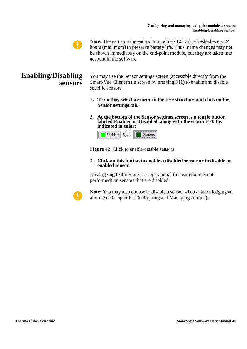
2. At the bottom of the Sensor settings screen is a toggle button labeled Enabled or Disabled, along with the sensor’s status indicated in color:
Figure 42. Click to enable/disable sensors
3. Click on this button to enable a disabled sensor or to disable an enabled sensor.
Datalogging features are non-operational (measurement is not performed) on sensors that are disabled.
Note: You may also choose to disable a sensor when acknowledging an alarm (see Chapter 6 - Configuring and Managing Alarms).
Thermo Fisher Scientific Smart-Vue Software User Manual 45

Configuring and managing end-point modules / sensorsAdding a measurement unit
Adding ameasurement unit
You may create a new measurement unit to assign to a Smart-Vue 4-20 mA sensor. This enables you to use Smart-Vue Client to display readings that are meaningful in your context.
1. Press F11 in the main Smart-Vue Client screen to access sensor settings. Select a 4-20 mA sensor from the list.
2. On the Sensor settings tab, click on the + on the right-hand panel of the Unit drop-down menu.
Figure 43. Add your own measurement units for 4-20 mA end-point modules
46 Smart-Vue Software User Manual Thermo Fisher Scientific

Configuring and managing end-point modules / sensorsAdding a measurement unit
3. This displays the measurement unit screen.
Figure 44. Measurement unit details
4. Use this window to add your own measurement units for the 4-20 mA sensor.
• Enter the name of the unit you wish to add in Unit name (#1 in Figure 44)
• Enter abbreviation of up to three characters in Unit symbol (#2)
• Enter the high and low limits (#3) (acceptable values for these fields range from -500 to +999).
5. Click on OK (#4) to confirm the new unit.
This new unit is automatically added to the drop-down menu for assigning units to sensors. Select the appropriate unit for the sensor in question and save your changes by closing the Sensor settings screen.
3
2
4
1
Thermo Fisher Scientific Smart-Vue Software User Manual 47

Configuring and managing end-point modules / sensorsAdding a measurement unit
The symbol and the high and low limits are transmitted to the end-point module when SEA (Spontaneous Emission of Alarms) is updated at this time.
Figure 45. Updated measurement unit list
Note: By default, the 4-20mA units are assigned to 4-20 mA sensors upon initialization.
You may change existing units for these values in the Add unit of measurement screen described above by typing their exact names. Their symbols and high and low limits will then be updated.
48 Smart-Vue Software User Manual Thermo Fisher Scientific

Configuring and managing end-point modules / sensorsAutomatic end-point module reconnection via SDP
Automatic end-pointmodule reconnection
via SDP
Smart-Vue end-point modules have the ability to reconnect automatically to the system if a transmission problem occurs. This feature may be activated or deactivated using a checkbox located at the bottom of the Sensor Settings screen (F11 from the main Smart-Vue Client screen), as shown below:
Figure 46. Click to enable automatic reconnection
If this checkbox is selected, the option is activated for all end-point modules that were added to the system using the SDP installation method. These end-point modules will seek to reconnect to their configured receiver if their wireless connection becomes unavailable and remains unavailable for 6 hours.
Note: This option is activated or deactivated for a given end-point module on the next update of SEA parameters that follows the change in this checkbox. Spontaneous Emission of Alarms (SEA) is when the sensor instantly transmits an alarm wirelessly to the system, without waiting for programmed data transfer.
Using correctionparameters
On the Sensor correction parameters tab shown below, you may load A and B correction parameters for the selected sensor. To do this:
1. Click on Modify (the button label changes to Validate).
Thermo Fisher Scientific Smart-Vue Software User Manual 49
Configuring and managing end-point modules / sensorsUsing correction parameters
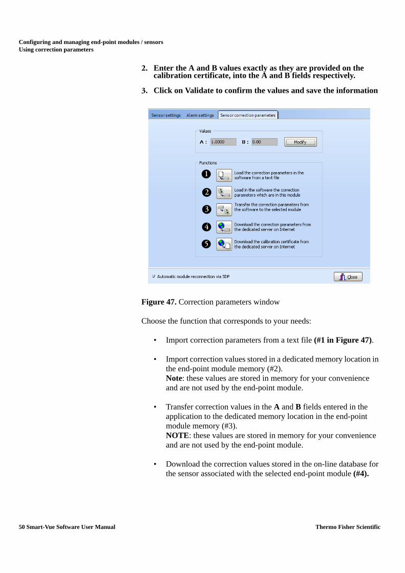
2. Enter the A and B values exactly as they are provided on the calibration certificate, into the A and B fields respectively.
3. Click on Validate to confirm the values and save the information
Figure 47. Correction parameters window
Choose the function that corresponds to your needs:
• Import correction parameters from a text file (#1 in Figure 47).
• Import correction values stored in a dedicated memory location in the end-point module memory (#2). Note: these values are stored in memory for your convenience and are not used by the end-point module.
• Transfer correction values in the A and B fields entered in the application to the dedicated memory location in the end-point module memory (#3). NOTE: these values are stored in memory for your convenience and are not used by the end-point module.
• Download the correction values stored in the on-line database for the sensor associated with the selected end-point module (#4).
2
5
4
3
1
50 Smart-Vue Software User Manual Thermo Fisher Scientific

Configuring and managing end-point modules / sensorsUsing correction parameters
• Download the calibration certificate associated with the selected end-point module into (#5):
• If downloading from the PC hosting Smart-Vue Server:
C:\SmartVue\SVuClient\certificates.
• If downloading from a PC only running Smart-Vue Client and not running Smart-Vue Server:
C:\Program Files\Thermo\Smart-Vue\certificates
Note: Correction parameters and calibration certificates may be downloaded for your sensor(s) only if:
• The sensor has been initially supplied to you calibrated or has been re-calibrated by Thermo Fisher Scientific.
• The workstation you are using is connected to the Internet
Thermo Fisher Scientific Smart-Vue Software User Manual 51

Configuring and managing end-point modules / sensorsAltitude settings (for CO2 sensors only)
Altitude settings (forCO2 sensors only)
Due to atmospheric pressure, readings taken by CO2 end-point modules are influenced by altitude. Follow these instructions to configure Smart-Vue System to compensate for the altitude of your system and calibrate readings accordingly. Here we assume that the CO2 end-point modules being used are within relatively close proximity to your server.
Note: Altitude adjustment can only be configured on the computer hosting Smart-Vue server via Smart-Vue Client.
1. On the Settings tab, click on (Altitude settings). The default altitude is 0 m.
Figure 48. Altitude settings for CO2 end-point modules
2. Enter the altitude where your server is located.
3. Select meters or feet.
4. Click on OK when done, or on Cancel to discard changes.
52 Smart-Vue Software User Manual Thermo Fisher Scientific

Displaying sensors and measurementsViewing sensor settings
Chapter 5 Displaying sensors and measurements
Viewing sensorsettings
Follow these steps to assign sensors to a particular user:
Note: Only Super Administrators can access the screen for assigning sensor viewing.
1. In the Settings tab, click on the View sensors icon ( ), or press F2, for sensor viewing settings
Figure 49. Assigning viewable sensors to users
2. Choose a user from the user account drop-down menu (#1 in Figure 49).
3. Click in the tree structure check boxes (#2) to check the receivers, groups and sensors you would like this user to be able to view within Smart-Vue Client. If no specific view is defined of a user, the default setting is for him or her to see all sensors.
You may select or deselect the entire tree structure at once in a single click using the dedicated buttons at the top of the screen (#4).
2
5
4
3
1
Thermo Fisher Scientific Smart-Vue Software User Manual 53

Displaying sensors and measurementsDisplaying sensors on the main screen
When you select a sensor in the tree structure (#2), you will see a short summary of its settings on the right-hand panel of the screen under Sensor characteristics (#5).
4. Save changes by clicking on Apply (#3).
Note: When a user adds a new sensor to the system, the sensor is added automatically to the list of sensors that the user in question can see.
Displaying sensorson the main screen
Smart-Vue Client’s main screen allows you to visually monitor the status of all sensors you are authorized to view:
Figure 50. Smart-Vue Client main screen
The tree structure in the left-hand panel shows a simple representation of all elements you are set up to view (receivers, groups and sensors). The icon color next to each sensor indicates its current status:
• Light green: temperature is within programmed high and low alarm limits.
• Orange: pre-alarm status (or delaying an alarm)
• Red: alarm status
• Dark green: disabled
2
31
54 Smart-Vue Software User Manual Thermo Fisher Scientific

Displaying sensors and measurementsDisplaying sensors on the main screen
• Grayed-out: technical fault such as communication failure or sensor fault
Note: You may double-click on a sensor in the tree structure (#1 in Figure 50) to open a screen with complete details about the sensor (see the “Displaying sensor readings” and “Displaying sensor settings” sections later in this chapter).
On the left-hand panel of the main screen, click on Overview from the menu at the bottom of the screen (#2) to display a summary curve and various other information about the selected sensor.
Figure 51. Sensor overview
Thermo Fisher Scientific Smart-Vue Software User Manual 55

Displaying sensors and measurementsDisplaying sensors on the main screen
For each sensor, the main display (#3) shows a small square zone that indicates the most important information:
Figure 52. Details for each sensor
1. Sensor name. Double-click on the name to display this sensor’s details (see the “Displaying sensor readings” and “Displaying sensor settings” sections later in this chapter).
2. Last recorded temperature. The date and time this temperature was measured is displayed when you hold your cursor over the value.
3. Maximum temperature recorded during a defined period of time. The default setting is the last 24 hours. This period of time can be defined in the sensor details window.
4. Average temperature recorded during a defined period of time. The default setting is the last 24 hours. This period of time can be changed in the sensor details window by selecting a date range or customizing a date range in the “Apply a filter” using the drop-down menu.
5. Minimum temperature recorded during a defined period of time. This period of time can be changed in the sensor details window by selecting a date range or customizing a date range in the “Apply a filter” using the drop-down menu.
6. Sensor status. Indicated in a variable-colored rectangle:
Light green: temperature is within programmed high and low alarm limits.
Orange: one of the temperature limits has been exceeded and the sensor is in a delay state, or one of the pre-alarm limits has been exceeded.
Red: one of the limits has been exceeded and an alarm has been triggered.
Dark green: sensor is disabled.
Gray: technical fault such as communication failure or sensor fault.
Note: You may enable a sensor that was previously disabled by double-clicking on its dark green or brown colored rectangle.
1
23
54
6
78
9
56 Smart-Vue Software User Manual Thermo Fisher Scientific

Displaying sensors and measurementsDisplaying sensors on the main screen
7. Date and time of the highest temperature during the defined period.
8. Sensor’s measurement units.
9. Date and time of the lowest temperature during the defined period.
Four different layout options exist for displaying your sensors in the monitoring area. Click on the icons below in the View tab to choose the display you want:
Figure 53. Sensor view layout options
Sort by sensor With this option, sensors are displayed in the order in which they were added to the system:
Figure 54. View sorted by sensor
Sort by sensor Floor plan mode
Sort by group Sort by receiver
Thermo Fisher Scientific Smart-Vue Software User Manual 57

Displaying sensors and measurementsDisplaying sensors on the main screen
Sort by group With this option, sensors are displayed on tabs labeled with the name of the group to which the sensors are assigned.
Figure 55. View sorted by group
Sort by receiver With this option, sensors are displayed on tabs labeled with the name of the receiver to which the sensors are assigned.
Figure 56. View sorted by receiver
58 Smart-Vue Software User Manual Thermo Fisher Scientific

Displaying sensors and measurementsUsing floor plans
Using floor plans For each defined group, Smart-Vue Client allows you to use an image representing your floor plan. For each group, you may then place sensors on the image according to their physical location.
Note: The default search folder for image files is C:\SmartVue\SVuClient\maps on the server hosting Smart-Vue Server. The easiest ways to load floor plans is to copy them to this folder. You may also choose to leave the image files in their original locations on the server. These folders will be used by the application. Image files may be in JPG or BMP format. The software does not resize the image, so the floor plan display depends on the resolution of your screen.
Figure 57. Sample dashboard display in floor plan mode
In order for a floor plan image to be available to all Smart-Vue Clients, it first needs to be loaded using the Smart-Vue Client application running on the PC hosting the Smart-Vue Server application. To do this:
1. In the tree structure window, select the group to which you want to add a floor plan image (#1 in Figure 58).
2. Click on Floor plan mode (#2).
3. Right-click on the dashboard (#3).
Thermo Fisher Scientific Smart-Vue Software User Manual 59
Displaying sensors and measurementsUsing floor plans
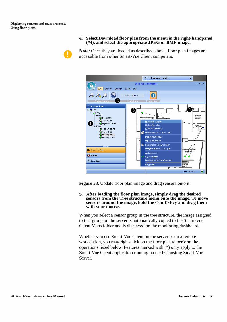
4. Select Download floor plan from the menu in the right-handpanel (#4), and select the appropriate JPEG or BMP image.
Note: Once they are loaded as described above, floor plan images are accessible from other Smart-Vue Client computers.
Figure 58. Update floor plan image and drag sensors onto it
5. After loading the floor plan image, simply drag the desired sensors from the Tree structure menu onto the image. To move sensors around the image, hold the <shift> key and drag them with your mouse.
When you select a sensor group in the tree structure, the image assigned to that group on the server is automatically copied to the Smart-Vue Client Maps folder and is displayed on the monitoring dashboard.
Whether you use Smart-Vue Client on the server or on a remote workstation, you may right-click on the floor plan to perform the operations listed below. Features marked with (*) only apply to the Smart-Vue Client application running on the PC hosting Smart-Vue Server.
2
3
1
4
60 Smart-Vue Software User Manual Thermo Fisher Scientific

Displaying sensors and measurementsUsing floor plans
Update floor plan Use this feature to force replacement of the floor plan image stored by client, when this image has been updated with a file of the same name. Smart-Vue Client automatically downloads the latest floor plan image assigned to the group if it has a different name than that which is currently being used.
Delete floor plan * You may erase the floor plan currently assigned to the selected group.
Delete sensors from floorplan
The floor plan image remains on the display for the selected group, but the sensors are removed.
Display sensor name As its name suggests, this option displays the name of each sensor beneath its circle symbol for all groups in the tree structure.
Display last reading This option displays the last-read value beneath each sensor’s circle symbol for all groups in the tree structure.
Position receiver on floorplan
Lets you place your receiver on the current floor plan by clicking with the mouse. The receiver is indicated by a blue square ( ).
Delete receiver from plan Removes the receiver from the current floor plan.
Add repeaters The Repeater list displays all repeaters, as well as all end-point modules being used as a repeater. You may drag a repeater onto the floor plan from this list. It is necessary to then use the Show Repeaters function to
Thermo Fisher Scientific Smart-Vue Software User Manual 61

Displaying sensors and measurementsUsing floor plans
make the repeaters visible on your floor plan, where they are shown as black squares ( ). You may relocate the repeater on this floor plan by clicking and dragging the repeater while holding the shift key.
If the repeater is also used as an end-point module, the icon on the floor plan will show both a circle and a square ( ).
Show repeaters Lets you view the repeaters, and wireless links between receivers, repeaters and end-point modules for the group selected.
Range test Runs a wireless signal strength test for an individual end-point module, and displays the result as a percentage. The mouse cursor must be over the sensor’s circle symbol when you right-click to open the contextual menu.
62 Smart-Vue Software User Manual Thermo Fisher Scientific

Displaying sensors and measurementsCollecting readings with Smart-Vue Client
Collecting readingswith Smart-Vue
Client
Programmed datatransfer
Smart-Vue Client automatically downloads readings stored by the sensors according to programmed data transfer intervals (see the “Configuring sensors” section in Chapter 4).
On-demand read of asingle end-point module
On the monitoring dashboard of the Smart-Vue Client main page, double-click on the latest reading displayed by a sensor to perform an on-demand read. An on-demand read will download all recorded values since the last transmission. If there are no new values to download, the end-point module will take a measurement at that point in time, and download this value to the database.
On-demand reads do not apply when viewing sensors in Floor plan mode.
Figure 59. Click on top-most value to perform on-demand read
Note: On-demand read values will not trigger an alarm limit.
On-demand read of allend-point modules.
To read all sensors in a single operation:
1. In the Smart-Vue main menu, click on Tools ==> (Rescan all sensors).
2. The system will read each sensor, one after the other, to collect all the latest readings for each.
On-demand read ofselected end-point
module
To read selected sensors in a single operation:
Thermo Fisher Scientific Smart-Vue Software User Manual 63

Displaying sensors and measurementsCollecting readings with Smart-Vue Client
1. In the Smart-Vue main menu, click on Tools ==> (Download saved data)
2. A sensor selection screen is displayed. Move the sensors for which you would like the system to download all logged readings from the Source list panel to the Destination list panel.
3. To do this, choose a sensor, and click on > (>> moves all the sensors). Repeat as necessary. The < and << buttons move a selected sensor back to the Source list. Click OK to confirm your selection.
Figure 60. Selecting sensors for data download
64 Smart-Vue Software User Manual Thermo Fisher Scientific

Displaying sensors and measurementsCollecting readings with Smart-Vue Client
4. A table shows an estimation of how many readings are to be downloaded from each sensor. The Send requests button launches the command to collect the desired readings. Readings will be performed by the system in sequence, one end-point module after another. You may close this window during the process.
Figure 61. Confirmation before downloading data from selected sensors
Thermo Fisher Scientific Smart-Vue Software User Manual 65

Displaying sensors and measurementsViewing individual sensor graphs
Viewing individualsensor graphs
Regardless of your user level in Smart-Vue Client, you may always check the data for the sensors you are authorized to view.
In order to view a graph for a given sensor, with complete measurement details as stored in the Smart-Vue Server database:
1. Double-click on the sensor name in the dashboard area or in the tree structure in the application’s main screen.
Figure 62. Double-click on a sensor name to access details
2. Then click to open the Graph tab, which displays sensor information:
Figure 63. Graph view options
66 Smart-Vue Software User Manual Thermo Fisher Scientific

Displaying sensors and measurementsViewing individual sensor graphs
The options in the menu bar are:
When you select the Annotations and events option, you may double-click on a point in the curve to add a comment. Double-clicking opens this dialog box so you can enter the desired text:
This drop-down menu contains several options for selecting the time period for your graph (all measurements, last 24 h, last week, last month, user-defined period).
Note: This value determines the number of sensor readings held in the application memory buffer. Whereas the Smart-Vue database contains the entire history of all sensor measurements, the value here determines the “working” data used by the application. The date range of your selection may have an effect on multi-curve displays, as described in the next section.Exports the graph and/or data in a variety of formats.Creates an e-mail message with graph data attached as a JPG image file.Prints the graph.
Saves graph in PDF format.
Closes the graph window.
, Zoom in and out on the graph, or reset the graph back to its original scale.Restore default view
, , , Move around the graph horizontally and vertically.Display measurement points on the curves.Change curve thicknessCenters graph within alarm limitsManual scaling (by entering values)Export to JPEG image fileTools to enhance the display with the overall trend, a smoothed graph, and your own annotations.
Thermo Fisher Scientific Smart-Vue Software User Manual 67

Displaying sensors and measurementsViewing individual sensor graphs
Figure 64. Entering a note on the graph
Note: You may switch the sensor detail display screen to full-screen using the icon in the upper right-hand corner of the display ( ) to see curves more clearly. We recommend that you zoom in on the graph to make it easier to add annotations.
68 Smart-Vue Software User Manual Thermo Fisher Scientific

Displaying sensors and measurementsViewing multiple sensor graphs
Viewing multiplesensor graphs
Multi-sensor /multi-graph display
To view sensor graphs with multiple sensors:
1. From the Smart-Vue main menu, click on Reports ==> (Graphs).
2. A sensor selection screen is displayed. Move the sensors for which you would like to display graphs from the Source list to the Destination list (click on the right arrows to add sensors from the left-hand side; click on the left arrows to remove sensors from the right-hand side).
3. Click on OK to confirm your selection. A colored curve is drawn using readings stored for each selected sensor. Use the checkboxes at the bottom of the screen to show or hide specific sensors. Curve colors are automatically assigned by the application.
Thermo Fisher Scientific Smart-Vue Software User Manual 69

Displaying sensors and measurementsViewing multiple sensor graphs
Figure 65. Sensor measurement graphs
You may use the mouse (click and drag inside the graph from top to bottom) to select and zoom into a specific area in the sensor graph.
The options in the menu bar are:
, Zoom in and out on the graph, or reset the graph back to its original scale.Restore default view
, , , Move around the graph horizontally and vertically.Display measurement points on the curves.Change curve thicknessPrints the graph display
Manual scaling (by entering values)Saves graph display in PDF format
Export to JPEG image fileExports the graph and/or data in a variety of formats.Displays graphs with 3-D reliefAdjusts 3-D settingsDate filter (see below) to select dates for display
70 Smart-Vue Software User Manual Thermo Fisher Scientific

Displaying sensors and measurementsViewing multiple sensor graphs
Using the date filter Use the date selection filter ( ) to adjust the dates for which to display graphs.
Note: The graph display feature uses the data stored in application memory, not the complete sensor database. Therefore, data for the dates you select using this date filter must be loaded in memory. By default, only data from the past 24 hours is loaded into Smart-Vue. To change this, adjust the data download period for each sensor you wish to view in a multicurve display, as described in the table on page 65.
Figure 66. Date filter for multi-curve display
Thermo Fisher Scientific Smart-Vue Software User Manual 71

Displaying sensors and measurementsDisplaying sensor readings
Displaying sensorreadings
To check readings for a specific sensor:
1. Double-click on the name of the desired sensor in the tree structure or in the dashboard area in the application’s main screen.
2. Click to open the Readings tab on the Sensor details screen, as shown here:
Figure 67. Sensor readings
The list of all readings logged by the end-point module for the time period selected using the drop-down menu/filter (#1 in Figure 67), and downloaded by the application, is presented in chronological order in a table, as shown above (#2).
You may export this data in various file formats, such as CSV or PDF. You may also export data directly to Microsoft Excel or Microsoft Word by clicking on the appropriate icon at the top of the screen (#3).
2
3
13
72 Smart-Vue Software User Manual Thermo Fisher Scientific

Displaying sensors and measurementsDisplaying sensor settings
Displaying sensorsettings
Display sensor settings for all end-point modules except dry contact end-point module.
1. Double-click on the name of the desired sensor in the tree structure or in the dashboard area in the application’s main screen.
2. Click to open the Settings tab on the Sensor details screen, as shown here:
Figure 68. Detailed sensor settings
This tab summarizes all of the information related to this sensor’s settings. This gives you an easy way to view the following (without modifying).
1. Sensor name and serial number
2. Alarm limits, pre-alarm limits, delay, as well as the highest and lowest values logged during the period stored in the sensor’s memory
3. Measurement interval and the average value over the period stored in the sensor’s memory
4. Wireless communication performance between the receiver, repeaters (if used) and the sensor (after clicking on Power)
2
1
3 4
65
Thermo Fisher Scientific Smart-Vue Software User Manual 73

Displaying sensors and measurementsDisplaying sensor settings
5. Other specific module information stored in Smart-Vue, displayed as a table (after clicking on Sensor state):
6. SEA settings read directly on the sensor, displayed as a table (after clicking on Status of SEA parameters). This is very convenient for making sure that the parameter information stored on the end-point module is indeed identical to that in the application. If high/low alarms are not set, then the sensor’s range limit values are displayed instead of High alarm and Low alarm. This table shows:
Field DescriptionModule number Module serial number (printed on sticker)Sensor number Sensor serial number (if applicable)Sensor name Name you assign to the sensor in Smart-Vue
ClientRepeater 1 Serial number of first repeater (if present)Repeater 2 Serial number of second repeater (if present)Repeater 3 Serial number of third repeater (if present)Datalogging enabled Whether or not module is set to store readingsRollover count The number of times that module memory has
filled and cycledNumber of readings Number of readings currently in module
memoryDate of last reading Date and time last reading was loggedMeasurement interval Currently-programmed measurement interval
Field DescriptionSEA enabled Spontaneous Emission of Alarms by moduleHigh range limit Highest tolerated value before issuing an alarmLow range limit Lowest tolerated value before issuing an alarmHigh delay Time to wait after reaching high limit before
sending alarmLow delay Time to wait after reaching low limit before
sending alarmNumber of alarm repeats
The number of times a given alarm will be sent
Delay between repeats How long the system waits before resending an alarm
Repeaters The number of repeaters used by module to reach receiver
Repeater 1 Serial number of first repeater (if present)Repeater 2 Serial number of second repeater (if present)Repeater 3 Serial number of third repeater (if present)Receiver address Serial number of the receiver to which module is
connected
74 Smart-Vue Software User Manual Thermo Fisher Scientific

Displaying sensors and measurementsDisplaying sensor settings
tesed)as
om
tesd)asin
Sensor settings forSmart-Vue dry contact
module
The Smart-Vue dry contact module has slightly different options on the Sensor details screen, as shown below:
Figure 69. Detailed sensor settings for dry contact module
Which states(open or closed)cause alarm, as
read in Smart-Vue
Client
Which states(open or closed)cause alarm, as
read from modulememory
Thermo Fisher Scientific Smart-Vue Software User Manual 75

Configuring and managing alarms Configuring alarms
Chapter 6 Configuring and managing alarms
Configuring alarms You must be connected to Smart-Vue Client as a Super Administrator or Administrator in order to configure alarms.
1. Click on Settings ==> (Sensor settings) or press F11, to open the sensor settings screen.
2. Choose a sensor from the tree structure on the left-hand panel (#1 in Figure 70), and then click on the Alarm settings tab.
Figure 70. Alarm settings tab in sensor settings except dry contact.
1
76 Smart-Vue Software User Manual Thermo Fisher Scientific

Configuring and managing alarms Enabling and setting limits
Alarm settings for drycontact module
The alarm settings screen is slightly different for dry contact modules, as shown here (described in more detail in the following paragraphs)
Figure 71. Alarm settings tab in sensor settings for dry contact.
Enabling and settinglimits
Enabling and setting limits for all end-point modules except dry contact end-point modules.
1. Click on/off to enable/disable high and low light alarms (#1 in Figure 72), and then set the limits.
2. You may enter values directly after double-clicking in the value field (#2), or use the up/down arrows (#3)
Figure 72. Enabling limits for a temperature sensor
2 1
3
Thermo Fisher Scientific Smart-Vue Software User Manual 77

Configuring and managing alarms Enabling and setting limits
Note: Delay is the period of time for which the temperature may exceed a limit without generating an alarm. Delay is limited to 4 hours. The corresponding alarm must be enabled to set the delay time.A pre-alarm value can be set as an early warning that an endpoint module may be headed towards an alarm condition. This field is not required, and serves only to provide a visual clue to the user. Pre-alarms do not initiate an alarm condition. Prealarm is not available for dry contact.
Pre-alarms and delays are set and enabled in the same manner.
Enabling and settinglimits for dry contact
end-point modules.
Dry contact modules offer the following options:
1. Click On/Off to enable/disable alarms (#1 in Figure 73) when the dry contact module detects opening or closing, and then set the time to wait before sending the alarm (delay).
2. You may enter values directly after double-clicking in the value field (#2), or use the up/down arrows (#3).
Figure 73. – Enabling limits for a dry contact sensor
Choosing SpontaneousEmission of Alarms
settings (SEA)
Click the Disable spontaneous alarm transmission checkbox if you wish to disable SEA for the sensor.
2
1
32
1
3
78 Smart-Vue Software User Manual Thermo Fisher Scientific

Configuring and managing alarms Enabling and setting limits
If this box is checked, the end-point module will send out SEA based on the high and/or low alarm limits. If this box is not checked high and/or low alarm will only be transmitted at the programmed transfer interval.
Figure 74. SEA settings
Probe fault alarm If this box is checked, the end-point module will send out an alarm as soon as an immediate sensor fault is detected. If this box is not checked and a sensor fault is detected, the end-point module will send out an alarm only at the programmed transfer interval.
Low battery alarm Activates alarm in case end-point module battery is low.
Note: Spontaneous Emission of Alarms (SEA) is when the sensor instantly transmits an alarm wirelessly to the system, without waiting for programmed data transfer.
Setting SEAretransmission
Here you may set the number of times the end-point module will try to send an alarm if a problem is detected, as well as the time between retries.
Thermo Fisher Scientific Smart-Vue Software User Manual 79

Configuring and managing alarms Acknowledging alarms
In the example, if the end-point module fails to communicate with the system, it will try 5 times, with 60 seconds between retries.
Figure 75. SEA retry values
Acknowledgingalarms
When the system triggers an alarm, whether a technical alarm (e.g., communication problem, sensor disconnection) or limit alarm, all currently open Smart-Vue Client sessions will move the Client main window to be on top of any other open windows.
For limit alarms, the sensor’s colored rectangle in the dashboard area turns red and displays the word Alarm.
Figure 76. Alarm indicator
Field indicates alarmcondition on thissensor.
80 Smart-Vue Software User Manual Thermo Fisher Scientific

Configuring and managing alarms Acknowledging alarms
In the application’s main screen, you may display unacknowledged alarms concerning your sensors by clicking on the Alarms button in the lower left-hand corner:
Figure 77. Alarm list in main dashboard
To acknowledge an alarm, double-click the corresponding line in the alarm list or select the corresponding line from the alarm list and click on the red acknowledgement button( ) The following screen is displayed after identification:
Figure 78. Entering description for alarm acknowledgement
Place thecursor over analarm to seedetails in thepop-upinformationbubble.
Limit alarms are displayed
Technical alarms
in blue text.
in red text.
are displayed
2
5
3
6
1
4
7
Thermo Fisher Scientific Smart-Vue Software User Manual 81

Configuring and managing alarms Acknowledging alarms
Alarm acknowledgementscreen
1. The upper part of the screen (#1 in Figure 78) provides a summary of key information about the alarm, including the type of alarm, when it occurred and when it ended
2. To acknowledge the alarm you must enter a description in the Cause of incident field (#2). Write your own text or choose existing text from the drop-down menu. You may also add choices to this list by clicking on (#3), or from the main Smart-Vue menu by selecting Settings ==> (Acknowledgment responses) ==> .
Figure 79. Entering custom acknowledgements
3. You may also enter text in the Corrective action (#4) and Option of control (#5) fields. These fields are not required.
4. If necessary, you may click on Disable sensor (#6 in Figure 80) to turn off the sensor before closing the alarm acknowledgement
82 Smart-Vue Software User Manual Thermo Fisher Scientific

Configuring and managing alarms Acknowledging alarms
window. This action stops data-logging on the sensor in question (see the “Enabling/disabling sensors” section in Chapter 4).
5. Click on OK (#7) to confirm the acknowledgement and close the window. The alarm line is automatically removed from the list on the application’s main screen.
Figure 80. Select a cause to acknowledge an alarm
6 7
Thermo Fisher Scientific Smart-Vue Software User Manual 83

Configuring and managing alarms Looking up alarm lists
Looking up alarmlists
You may view and print alarms at any time in Smart-Vue Client, including a complete list of alarms for all the sensors in your view
1. In the main Smart-Vue menu, click on Reports ==> (Alarm status)
2. The screen below opens with a list of all the alarms that occurred over the past week (the time period can be adjusted) for all the sensors in your view..
Figure 81. Viewing and printing alarms
3. Use the tree structure (#1 in Figure 81) to filter the alarms displayed by type and/or by acknowledgement status.
4. Use the drop-down menu (#2) to specify the period of time for which you wish to display alarms.
5. The table (#3) refreshes automatically according to your selection.
6. Use the horizontal scroll bar (#4) to navigate through the columns in the table.
7. Use the buttons in the menu bar (#5) above the table to export the data to Microsoft Excel or Microsoft Word, or to print the table.
Listing all alarmsgenerated for one of the
sensors in your view
To list all alarms for a particular sensor
1. Double-click on the sensor name in the tree structure in the Smart-Vue main screen.
4
2
1
3
5
4
84 Smart-Vue Software User Manual Thermo Fisher Scientific

Configuring and managing alarms Looking up alarm lists
2. Click on the Alarm list tab in the Sensor details screen..
Figure 82. Alarm list for a specific sensor
3. Use the tree structure (#1 in Figure 82) to filter the alarms displayed by type and/or by acknowledgement status.
4. Use the drop-down menu (#2) to specify the period of time for which you wish to display alarms. The table (#3) refreshes automatically according to your selection.
5. Use the horizontal scroll bar (#4) to navigate through the columns in the table
6. Use the buttons in the menu bar (#5) above the table to export the data in PDF format or to print the table.
Figure 83. Sample alarm list printout from the sensor’s details
3
4
1
2
3
5
4
Thermo Fisher Scientific Smart-Vue Software User Manual 85
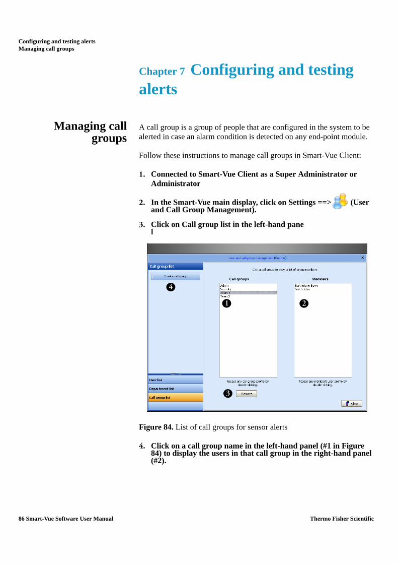
Configuring and testing alertsManaging call groups
Chapter 7 Configuring and testing alerts
Managing callgroups
A call group is a group of people that are configured in the system to be alerted in case an alarm condition is detected on any end-point module.
Follow these instructions to manage call groups in Smart-Vue Client:
1. Connected to Smart-Vue Client as a Super Administrator or Administrator
2. In the Smart-Vue main display, click on Settings ==> (User and Call Group Management).
3. Click on Call group list in the left-hand panel
Figure 84. List of call groups for sensor alerts
4. Click on a call group name in the left-hand panel (#1 in Figure 84) to display the users in that call group in the right-hand panel (#2).
1
3
4
2
86 Smart-Vue Software User Manual Thermo Fisher Scientific

Configuring and testing alertsManaging call groups
5. You may delete a call group by selecting it in the list and clicking on Remove (#3). You will be prompted to confirm deletion if the call group in question is currently used by the system in alert settings. Note: you may double-click on a group or user name to access profile details directly.
6. Create a new group by clicking on Create call group (#4) in the left-hand panel’s menu bar. This opens a new call group profile form
Figure 85. New call group profile form
7. Enter a name for the new call group (#5 in Figure 85). This name must not already be in use by another call group.
8. Use the Department drop-down menu (#6) to choose a department and display its members (#7).
9. Click to select the members you wish to add to this call group.
10. Use the right and left arrows (#8) to add and remove members from the call group table (#9). You may add users from multiple departments to any given call group.
11. After adding all the desired members to the group, use the up and down arrows (#10) on the right-hand side of the screen to arrange them in priority order. Members are contacted one after the other, moving down the list, in case of an alert concerning this call group.
6
5
8
97
10
Thermo Fisher Scientific Smart-Vue Software User Manual 87

Configuring and testing alertsConfiguring alerts for groups and receivers
12. Click on OK to confirm the new group and add it to the system. You may access the call group’s profile at any time in order to make changes.
Note: You may open and change user settings directly from a call group form by double-clicking in the list on the left-hand panel (#7) or on the table (#9).
Configuring alertsfor groups and
receivers
With Smart-Vue Client, you can store a different alert configuration for each receiver and group in your view. This configuration applies automatically to all the technical and limit alarms it covers.
Follow these instructions to configure alerts in Smart-Vue Client:
1. Connect to Smart-Vue Client as a Super Administrator or Administrator.
2. In the Smart-Vue main display, click on Settings ==> (Alert settings) or press F8.
3. The Alert management screen is displayed. Click on the Group settings tab as shown below.:
Figure 86. Alert management screen
6
5
2
8
9
1
3 45
65
78
10
2
88 Smart-Vue Software User Manual Thermo Fisher Scientific

Configuring and testing alertsConfiguring alerts for groups and receivers
4. In the tree structure on the left-hand panel (#1 in Figure 86) select the group you would like to configure.
5. Define the start and end-times for the days of the week and the weekend for this group (#2). These settings are used by the software to determine the start and end of each of the three alarm periods: day, night, and weekend. (See Chapter 3- Managing Users.)
6. Click on the call group(s) of your choice in the list of Available call groups (#3), and move it (or them) to or from the table of Selected call groups using the right and left arrows (#5).
7. Organize call group priority using the up and down arrows on the right (#6). Alerts are handled in descending order through this list (#4)
Note: You may open the call group profile at any time for viewing or to make changes by double-clicking on its name in either the list (#3) or the table (#4).
Printed alerts You may also configure a document to be printed in case of an alarm. To do this, click on the Printer alert (#7) checkbox and assign a printer for day, night, and weekend times.
Note: The printer list in the application is generated by Smart-Vue Server based on the printers installed on the server (either locally or on the network). If you add a new printer, you must restart the server application for the printer to be visible.
Activating other types ofalerts
To activate an audio or light unit, dry contact or siren, click on the checkbox next to the Audio unit… option (#8) and assign a device by clicking on + (see the “Adding audio and visual alert devices” section in this chapter).
Two other options are also available:
Repeat sequential dial-out for telephone alerts (#9): If an alarm is triggered and all users in all the associated call groups have been contacted but none of them has acknowledged the call by pressing *2 on the telephone keypad, the system resumes calling, starting at the beginning of the list. This cycle continues until one contact confirms reception of the alarm by pressing *2 on their telephone keypad or up to 10 cycles.
Repeat alerts at each transfer interval (#10): If a sensor is still in an alarm state, all alerts (not just telephone alerts) are triggered each time data is transferred, even if the initial alert was acknowledged.
Thermo Fisher Scientific Smart-Vue Software User Manual 89

Configuring and testing alertsConfiguring alerts for groups and receivers
Note: Technical alarms are not repeated with this function, just limit alarms.
Configure the alerts for all your sensor groups in this manner, and click on OK to save your changes.
Note: You must also configure alerts in case there is a problem with your wireless receivers. To do this, select each receiver in the tree structure on the left-hand panel of the screen (#1). Configuration, in this case, is identical to that for groups, except alarms are not re-triggered. The alerts you configure for receivers are automatically resent if the receiver is not communicating.
Note: For alerts, you may use custom .WAV files. These files need to meet the following specifications: 128 kps, 16-bit, mono, 8 kHz sampling rate, PCM format.
Three files are used for telephone alerts. Their names must be "Limit Alarm.wav", "Technical Alarm.wav" and "Alarm Acknowledgment.wav" located in: C:\SmartVue\Svuserver\Sound. These files must not be moved or renamed.
90 Smart-Vue Software User Manual Thermo Fisher Scientific

Configuring and testing alertsAdding the wireless siren to your system
Adding the wirelesssiren to your system
1. Select Settings ==> Alert Settings ( ) or press F8. Alerts are configured for either groups or receivers.
2. To add a wireless siren, click on the desired group or receiver (#1 in Figure 87).
3. Click to select the checkbox Audio and visual wireless siren (#2).
Figure 87. Adding a wireless siren to your system
4. Depending on when you wish to use this siren, click on the plus sign (+) next to Day, Night or WE (weekend) in the lower right-hand part of the screen (#3).
1
32
Thermo Fisher Scientific Smart-Vue Software User Manual 91

Configuring and testing alertsAdding the wireless siren to your system
5. In the Siren field (#4 in Figure 88), enter the wireless address printed on the label on the siren, then click on Power (#5). The signal power level must be 30% or higher to ensure reliable communications.
Figure 88. Add the siren to a receiver (Lab_1 in this example)
6. Click on Add (#6) ==> OK (Select) (#7) ==> OK to confirm addition of the new siren.
At this point the siren is up and running, ready to react if an alarm condition is detected on any end-point module in the specified group or receiver.
Note: Sirens function independently of other alerts, such as telephone and fax alerts. Therefore, you do not have to configure Call Groups if you intend to use siren alerts only.
4
7
6
5
92 Smart-Vue Software User Manual Thermo Fisher Scientific

Configuring and testing alertsConfiguring local alerts
Configuring localalerts
Local alerts are played in the local session of Smart-Vue Client.
Follow these instructions to configure local alerts:
1. Login to Smart-Vue Client as a Super Administrator or Administrator.
2. In the Smart-Vue main display, click on Settings ==> (Alert settings) or press F8.
3. Click on the Local settings tab:
Figure 89. Local settings in the Alert management screen
4. Alerts configured on this tab are triggered by Smart-Vue Client for any alarm for which they are programmed. Therefore, the application must be running.
5. You may choose to play sound files (.WAV) if a limit is exceeded (#1 in Figure 89) or a technical alarm (#2) is detected. You may disable local technical alerts (#3).
6. Sequential triggering may be programmed (#4), in which case alerts are triggered for limit alarms each time a read value indicates a limit was exceeded.
Note: For local alerts, you may use custom .WAV files.Local alert settings are configured independently on each PC running Smart-Vue Client.
1 2
3 4
Thermo Fisher Scientific Smart-Vue Software User Manual 93

Configuring and testing alertsConfiguring periods without alerts
Configuring periodswithout alerts
You can disable alerts for specific periods, depending on your requirements. Follow these instructions to configure periods when alerts will not be sent :
1. Connect to Smart-Vue Client as a Super Administrator or Administrator.
2. In the Smart-Vue main display, click on Settings ==> (Alert settings) or press F8.
3. Click on at the bottom of the screen. This opens the Alert-free period screen. Here you may configure periods during which alerts are not sent..
Figure 90. Configuration screen for periods without alerts
Select a sensor from those in your view within the tree structure (#1 in Figure 90), and use the calendar to define the time slots (#2) in the week during which alerts are disabled. Click on a time slot to change its status. You can click and drag the mouse to choose multiple time slots at once.
Figure 91. Click on a time-slot to toggle enabled/disabled selection
If a technical or limit alarm is triggered during a time slot that is set to Off for a sensor, the alarm is automatically acknowledged by the system and no alert is issued.
1 2
94 Smart-Vue Software User Manual Thermo Fisher Scientific

Configuring and testing alertsConfiguring periods without alerts
Setting holidays Smart-Vue Client handles holidays using weekend settings (Saturday and Sunday). Follow these steps to set holidays:
1. Login to Smart-Vue Client as a Super Administrator or Administrator.
2. In the Smart-Vue main display, click on Settings ==> (Alert settings) or press F8.
3. Click on at the bottom of the screen. Simply double-click on those dates that are to be considered as holidays by Smart-Vue. Your selection of holidays is listed in the “My selection” column on the left-hand side of the screen.
Figure 92. Setting holidays for alert-free periods
4. You may delete individual holidays by selecting the holiday in question (in red), and clicking on Delete selected holiday.
If necessary, you may clear your entire selection at once by clicking on Delete all selected holidays.
5. Click on Exit when done.
Thermo Fisher Scientific Smart-Vue Software User Manual 95

Configuring and testing alertsStopping an audio or visual alert device
Stopping an audio orvisual alert device
As described in the previous sections in this chapter, a wireless siren may be activated in case of an alarm, depending on your settings. To stop a wireless siren:
1. Select the relevant alarm from the alarm list in the Smart-Vue Client main screen (left-hand panel).
Figure 93. Acknowledging alerts
2. Click on the siren icon to acknowledge and stop the alarm.
Note: If a wireless siren or local alert has been activated, this alert will be automatically stopped when the triggering alarm is acknowledged in Smart-Vue Client.
96 Smart-Vue Software User Manual Thermo Fisher Scientific

Configuring and testing alertsRunning a test alarm
Running a test alarm You may use Smart-Vue Client to simulate an alarm to test your various alert scenarios.
To do this
1. In the Smart-Vue main display, click on Tools ==> (Alert test).
2. The screen below is displayed:
Figure 94. Alarm test screen
3. Select a sensor in the tree structure (#1 in Figure 94).
4. Choose the type of alarm you wish to test, remote (#2) or local (#3).
1
2
3
Thermo Fisher Scientific Smart-Vue Software User Manual 97

Configuring and testing alertsRunning a test alarm
5. Then click on the appropriate Test button.
For remote alarms, a new line is inserted into the alarm list, with an artificial date such as 12/30/1899 to avoid disrupting the system log.
Figure 95. Test alarm with unrealistic time/date stamp
6. Make sure your test scenario runs as planned, and then acknowledge this fictitious entry to remove it from the list.
98 Smart-Vue Software User Manual Thermo Fisher Scientific

Configuring and testing alertsConfiguring alert system settings
Configuring alertsystem settings
This configuration option is only available in the Smart-Vue Client software running on the computer that is hosting Smart-Vue Server.
Follow these steps to configure the Smart-Vue Client alert system:
1. Connect to Smart-Vue Client as a Super Administrator or Administrator.
2. In the Smart-Vue main display, click on Settings ==> (Alert settings) or press F8. This opens the Alert management screen, shown below. Click on the System settings tab.
Figure 96. Alert system settings screen
1. In the Phone modem section (#1 in Figure 96), select the telephone modem and associated voice media to be used for handling alerts. You may also enter initialization strings to use for fax and SMS (mobile phone text message) communications.
2. The E-mail Server section (#2) contains configuration parameters related to your e-mail server. Enter the appropriate information for your system: SMTP Server Name, Login and Password if necessary, as well as the Server port to use (port 25 is the standard port for SMTP) and the e-mail address that will be used to identify the sender of alert messages.
1 2
Thermo Fisher Scientific Smart-Vue Software User Manual 99

Configuring and testing alertsConfiguring alert system settings
Note: For maximum reliability over time, we recommend that you test alerts after any change to verify proper operation. Also, we recommend testing at regular intervals to ensure that existing configurations continue functioning as they should, based on standard operating procedure.
Note: Check with your local IT department for mail server settings and create a user for sending alarms. Encrypted authentication (SSL,TLS) are not supported.
Some anti-virus programs may prevent e-mail from being sent until they are properly configured.
100 Smart-Vue Software User Manual Thermo Fisher Scientific
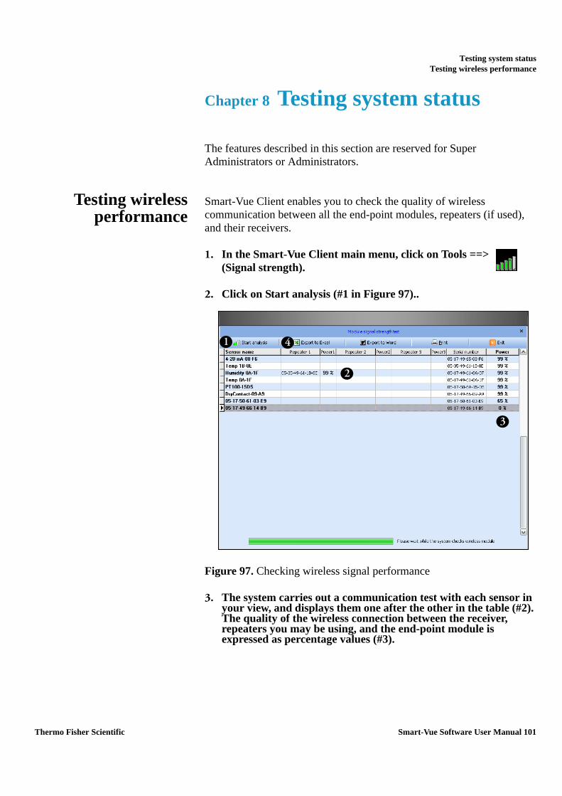
Testing system statusTesting wireless performance
Chapter 8 Testing system status
The features described in this section are reserved for Super Administrators or Administrators.
Testing wirelessperformance
Smart-Vue Client enables you to check the quality of wireless communication between all the end-point modules, repeaters (if used), and their receivers.
1. In the Smart-Vue Client main menu, click on Tools ==>
(Signal strength).
2. Click on Start analysis (#1 in Figure 97)..
Figure 97. Checking wireless signal performance
3. The system carries out a communication test with each sensor in your view, and displays them one after the other in the table (#2). The quality of the wireless connection between the receiver, repeaters you may be using, and the end-point module is expressed as percentage values (#3).
1
2
3
4
Thermo Fisher Scientific Smart-Vue Software User Manual 101

Testing system statusTesting wireless performance
Note: A wireless performance test in a Smart-Vue Server system is acceptable if the displayed percentages are 30% or higher. Below this level, communication with the end-point module may be impaired, which could result in a reduced ability to collect stored measurements or the initiation of alarms.
4. The buttons (#4) in the menu bar at the top of the screen can be used to export the table of obtained results to Microsoft Excel or Microsoft Word or to print it.
102 Smart-Vue Software User Manual Thermo Fisher Scientific

Testing system statusTesting battery counters
Testing batterycounters
To check the battery level in the end-point modules in your view:
1. In the Smart-Vue Client main menu, click on Tools ==> (Battery strength test).
2. Click on Start analysis (#1 in Figure 98) to begin testing.
Figure 98. Checking end-point module batteries
3. The system then queries the battery counter in each sensor in your view and displays the estimated percentage of battery strength remaining in a table as shown above (#2).
4. The buttons (#3) in the menu bar at the top of the screen can be used to export the table to Microsoft Excel or Microsoft Word or to print it.
1
2
3
Thermo Fisher Scientific Smart-Vue Software User Manual 103

Testing system statusTesting sensor data-logging status
Testing sensordata-logging status
At any time, you can check the status of data collection (reads) for each sensor in your view. To do this:
1. In the Smart-Vue Client main menu, click on Tools ==> (Datalogging state)
2. Click on Start analysis (#1 in Figure 99) to begin testing.
Figure 99. Data logging status window
3. The system queries each end-point module and collects information about its data-logging status, which is displayed in the table (#2).
You may use this feature to make sure that data-logging is running properly and to check the date and time of the last reading, the number of reads stored in memory, and the programmed interval.
If a problem is detected on the end-point module, the related line in the table is displayed in color. A legend describing the different colors is presented at the bottom of the screen (#3).
4. The buttons (#4) in the menu bar at the top of the screen can be used to export the table to Microsoft Excel or Microsoft Word or to print it
1
2
4
3
104 Smart-Vue Software User Manual Thermo Fisher Scientific

Archiving dataSelecting the archive period
Chapter 9 Archiving data
Smart-Vue Client lets you archive parts of its stored readings in a dedicated area in its database to lighten the system load and reduce processing time. This operation is reserved for Super Administrators only, and has no effect on the traceability of archived readings or their accessibility. Archives may be loaded at any time for viewing.
Selecting the archiveperiod
1. Click on the Smart-Vue Client icon in the upper left-hand corner of the main screen.
2. Click on Data ==> Archive readings.
Figure 100. Archiving Smart-Vue Client data
Thermo Fisher Scientific Smart-Vue Software User Manual 105

Archiving dataSelecting the archive period
3. This opens the Data archive screen shown here:
Figure 101. Data archive settings
Here you may choose one of the following options for archiving your data:
• Archive up to the last week: archives all measurement values older than one week.
• Archive up to last month: archives all measurement values older than one month.
• Archive up to selected date: archives all measurement values prior to a specified date.
• Archive all: archives all measurement values up to the present moment.
Click on OK to confirm your choice.
Note: We recommend that, at a minimum, you archive measurement values that are older than one year to optimize application operation and keep the system running smoothly.
106 Smart-Vue Software User Manual Thermo Fisher Scientific

Archiving dataDisplaying archived data
Displaying archiveddata
1. Click on the Smart-Vue Client icon in the upper left-hand corner of the main screen.
2. Click on Data ==> View archive.s
Figure 102. Opening Smart-Vue Client data archives
3. The Archive Displayed selection screen opens as shown here:
Figure 103. Selecting archive period to display
4. Set the time period for the archives you wish to view by selecting start and end dates using the two calanders.
5. Click on close. The system includes datat from archived readings in this peiod along with other current readings.
Thermo Fisher Scientific Smart-Vue Software User Manual 107
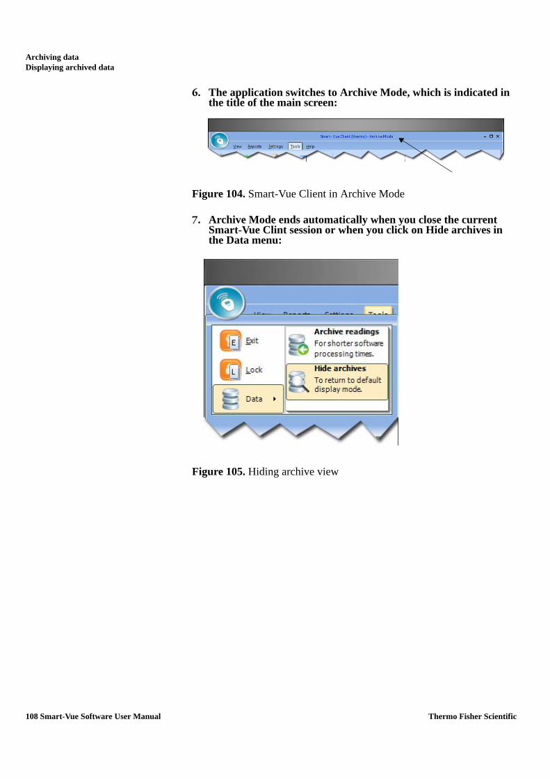
Archiving dataDisplaying archived data
6. The application switches to Archive Mode, which is indicated in the title of the main screen:
Figure 104. Smart-Vue Client in Archive Mode
7. Archive Mode ends automatically when you close the current Smart-Vue Clint session or when you click on Hide archives in the Data menu:
Figure 105. Hiding archive view
108 Smart-Vue Software User Manual Thermo Fisher Scientific

Printing and exporting reportsSensor report
Chapter 10 Printing and exporting reports
You can print several different types of reports summarizing system status using the printer(s) installed on your computer. The information contained in these reports can generally also be exported in various electronic file formats.
Sensor report 1. In the main Smart-Vue Client menu, click on Reports ==> (Sensor status).
2. Select the period you would like to cover in the report:
Figure 106. Printing sensor report
3. With this option, you may check sensor activity over the past 24 hours, week, month, or starting at a particular date.
4. Click on OK to confirm your selection.
Thermo Fisher Scientific Smart-Vue Software User Manual 109

Printing and exporting reportsSensor report
5. The report preview screen is then displayed:
Figure 107. Sensor report preview
Sensor report details This report shows sensor state (enabled/disabled), highest, lowest and average readings, most recent reading, and the number of alarms for the select period for each sensor in your view. Mean kinetic temperature is also displayed, as supported by specific end-point modules
Figure 108. Options in sensor report preview window
The toolbar along the top of the preview screen enables you to:
1. Change the screen display.
2. Navigate through documents that contain several pages.
3. Configure the printer and print the document.
4. Save the document in .PDF or .QRP format.
1 2 3 4 5 6
110 Smart-Vue Software User Manual Thermo Fisher Scientific

Printing and exporting reportsSensor report
5. Open an existing report in .QRP format in the same screen.
6. Close the screen.
Mean KineticTemperature (only fortemperature sensors)
Some products and devices have a faster rate of degradation at higher temperatures. For example, perishable food items, pharmaceutical products and many forms of bacteria can grow/degrade exponentially as the ambient temperature increases. Mean kinetic temperature is a calculation that accommodates the non-linear thermal effect that temperature can have on products. Mean kinetic temperature is represented as the equivalent temperature to which the product was thermally subjected during the period of time the various temperature readings were recorded.
The formula for calculating the mean kinetic temperature can be expressed as shown below:
Where:
For example, if the 5 data points for which you wish to calculate mean kinetic temperature are 12.3, 15.9, 16.2, 14.7 and 14.9 degrees Celsius, then the mean kinetic temperature would be 14.9 degrees Celsius.
Automating reportprint-out
All users can program the system to print their reports on a daily basis. To do this:
1. Click on Reports ==> (Automatic print-out).
mkt Mean kinetic temperature (in degrees Celsius)
ΔHActivation energy. Smart-Vue Client uses an activation energy value of 83.144 KJ/mol for the calculation.
R Universal gas constant, which is 0.0083144 KJ/mol K
n Number of data points to include in the calculation
ti A data point to include in the calculation (in degrees Celsius)
Thermo Fisher Scientific Smart-Vue Software User Manual 111

Printing and exporting reportsAlarm report
2. The Automatic print-out settings screen opens as shown here:
Figure 109. Automatic print-out settings
3. Click the Enabled checkbox (#1 in Figure 109)to enable automatic daily printing.
4. Select the time of day (24 hour clock where 5:00 pm is 17:00, 11:00 am is 11:00, etc.) to print the report (#2) as well as the printer (#3).
5. You can view the report by clicking Preview.
6. Confirm your configuration by clicking on OK (#4).
Note: Smart-Vue Client must be running (i.e. not in standby mode) at the scheduled time on the computer configured to print the status report automatically.
Alarm report To access the alarm report for the sensors in your view, click on
Reports ==> (Alarm status). See the “Looking up alarm lists” section in Chapter 6 for more details on this feature.
Settings report This report provides a summary of the settings on the sensors in your view.
1. To view the report, click on the Reports ==> (Settings status).
1
2
3
4
112 Smart-Vue Software User Manual Thermo Fisher Scientific

Printing and exporting reportsSettings report
2. The sensor parameters report is displayed as shown below.
Figure 110. Sensor settings report
This report includes information on sensor settings, including wireless settings, measurement and data transfer intervals, limits, delay, data-logging status, sensor number, correction coefficients and the most recent reading for each sensor in your view.
See the “Sensor reports” section earlier in this chapter for a description of the toolbar at the top of the Sensor settings screen. All the same features are available here as well (such as printing, and exporting data as .PDF or .QRP).
Thermo Fisher Scientific Smart-Vue Software User Manual 113

Printing and exporting reportsAdding a custom logo to your reports
Adding a customlogo to your reports
By default, the Thermo Scientific logo is included on reports generated by Smart-Vue Client. You may replace the logo with one of your own to personalize your reports. To do this
1. Click on Reports ==> (Customize logo).
2. The Customize logo screen is displayed, as shown here:
Figure 111. Changing the logo for your printed reports
3. Click on Select and locate the image that you want to use for the reports printed by Smart-Vue Client on your computer.
4. To restore the default image, click on Default.
Note: For optimal display quality, only bitmap (.BMP) images are supported. Image size should not exceed 100 x 57 pixels. If you use a larger image, only the center part will be used.
114 Smart-Vue Software User Manual Thermo Fisher Scientific

Viewing the event logViewing the event log
Chapter 11 Viewing the event log
Viewing the eventlog
All user events and actions that affect the system are recorded in a log you may view and print using Smart-Vue Client, regardless of your user profile.
To do this:
1. Click on Reports ==> (Event log) icon, or press F3.
2. The events log screen is displayed as shown here:
Figure 112. Event log screen
3. You may filter the report to limit the covered time period (#1 in Figure 112), focus on a particular user (#2), and/or sort by event type and action (#3).
4. Click on Search (#4) to refresh the table display (#5) according to your criteria.
5. Use the buttons in the horizontal menu bar at the top of the screen (#6) to export the table to Microsoft Word, Microsoft Excel, a PDF file, or to print your report.
1 23 4
5
6
Thermo Fisher Scientific Smart-Vue Software User Manual 115

Viewing the event logViewing the event log
This report provides a convenient way to monitor the activity of system users and see who performs setting changes.
Note: Events generated by the system, such as triggered alarms, are displayed when you select SYSTEM as the user name for this report.
116 Smart-Vue Software User Manual Thermo Fisher Scientific

Configuring and personalizing the applicationChoosing a visual theme
Chapter 12 Configuring and personalizing the application
Choosing a visualtheme
You may choose from three Microsoft Office 2003™ style visual themes in Smart-Vue Client.
1. Click on View.
2. Select the color scheme for your Smart-Vue Client display:
Figure 113. Smart-Vue visual themes
Office 2003 Blue Office 2003 Olive Office 2003 Silver
Thermo Fisher Scientific Smart-Vue Software User Manual 117
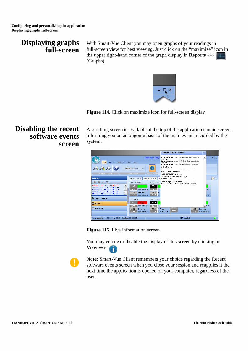
Configuring and personalizing the applicationDisplaying graphs full-screen
Displaying graphsfull-screen
With Smart-Vue Client you may open graphs of your readings in full-screen view for best viewing. Just click on the “maximize” icon in the upper right-hand corner of the graph display in Reports ==> (Graphs).
Figure 114. Click on maximize icon for full-screen display
Disabling the recentsoftware events
screen
A scrolling screen is available at the top of the application’s main screen, informing you on an ongoing basis of the main events recorded by the system.
Figure 115. Live information screen
You may enable or disable the display of this screen by clicking on View ==> .
Note: Smart-Vue Client remembers your choice regarding the Recent software events screen when you close your session and reapplies it the next time the application is opened on your computer, regardless of the user.
118 Smart-Vue Software User Manual Thermo Fisher Scientific

Configuring and personalizing the applicationDisabling settings protection
Disabling settingsprotection
Users with Super Administrator or Administrator rights may select the lock icon to prevent the need to provide login credentials each time they access Applications Setting Screens during a single session. However, the View Sensors (F2) screen and the Archive Data feature always require authentication regardless of the status of the lock icon.
Figure 116. Protecting access to settings screens
==> Locked
==> Unlocked
You may access this same feature by clicking on the Smart-Vue menu icon as shown below, then on Lock.
Note: Protection is automatically reactivated the next time the Smart-Vue Client application is opened.
1
Thermo Fisher Scientific Smart-Vue Software User Manual 119

Configuring and personalizing the applicationEnabling the 21 CFR Part 11 option
Enabling the 21 CFRPart 11 option
Smart-Vue includes a 21 CFR Part 11 option. If this option is changed on the Smart-Vue server (enabled or disabled), you must close all Smart-Vue Client applications and restart them for this change to take effect. This option slightly modifies Smart-Vue Client operation. Examples include, but are not limited to: requiring justification for making changes to sensor status, making changes to sensor settings, and the inability to make changes to the software protection feature.
A colored icon in the Settings menu bar in Smart-Vue Client indicates whether this option is currently enabled or disabled.
==> Option disabled (blue)
==> Option enabled (orange)
120 Smart-Vue Software User Manual Thermo Fisher Scientific

Configuring and personalizing the applicationAdvanced maintenance options
Advancedmaintenance options
Note: The features described here should only be used by experienced and qualified Smart-Vue Client technicians. Incorrect use of expert options could cause your solution to function incorrectly.
Smart-Vue Client includes an Expert section that may be used to verify and update basic receiver settings easily for troubleshooting purposes. Follow these steps if you are having problems with your system and would like to confirm proper operation of your receiver(s):
1. Login to Smart-Vue as Super Administrator.
2. Click on Tools ==> (Advanced maintenance), or press F12.
Thermo Fisher Scientific Smart-Vue Software User Manual 121

Configuring and personalizing the applicationAdvanced maintenance options
3. Click on the Smart-Vue tab:
Figure 117. Checking receiver properties in Advanced maintenance
4. To check and update a given receiver, use the Receiver Module pull-down menu to select the receiver.
5. Verify its COM port and Connection speed settings and click on Parameter update the configuration. This ensures that the Smart-Vue configuration file for the receiver in question is accurate.
122 Smart-Vue Software User Manual Thermo Fisher Scientific
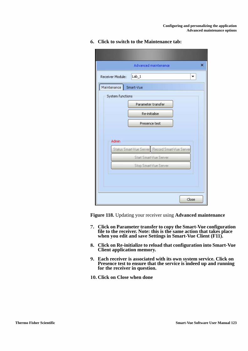
Configuring and personalizing the applicationAdvanced maintenance options
6. Click to switch to the Maintenance tab:
Figure 118. Updating your receiver using Advanced maintenance
7. Click on Parameter transfer to copy the Smart-Vue configuration file to the receiver. Note: this is the same action that takes place when you edit and save Settings in Smart-Vue Client (F11).
8. Click on Re-initialize to reload that configuration into Smart-Vue Client application memory.
9. Each receiver is associated with its own system service. Click on Presence test to ensure that the service is indeed up and running for the receiver in question.
10. Click on Close when done
Thermo Fisher Scientific Smart-Vue Software User Manual 123

Getting helpOpening the user manual
Appendix 1 Getting help
Opening the usermanual
The Smart-Vue Client Software User Manual is copied to the application’s folder on your computer as a .PDF file during installation.
Click on Help ==> (User manual) to open the manual.
Automaticallyupdating the user
manual
You need an Internet connection to download a new Thermo Scientific Smart-Vue Software User Manual. If for some reason the manual is not present in the Smart-Vue Client folder or if you want to download the latest version (and you have an internet connection):
1. Click on Help ==> (Download current manual) to download the latest PDF version of the manual/
2. When the download is finished, you may open the manual directly by clicking on Open in the Download screen.
124 Smart-Vue Software User Manual Thermo Fisher Scientific

Getting helpContact Information
Contact Information
By e-mail If you need help with your Thermo Scientific product, please send a detailed e-mail to us at the following address:
E-mail: [email protected]
Be sure to include as many details as possible, including specific product references, software versions and screen shots from your computer.
By phone • North and Central America: +1 866 984 3766 (866-9-THERMO)
• Europe: Austria +43 1 801 40 0Belgium +32 53 73 4241France +33 2 2803 2180Germany national toll free 0800 1 536 376Germany international +49 6184 90 6940
• Italy +39 02 95059 -340. -460, -207Netherlands +31 76 579 55 55Nordic/Baltic countries +358 9 329 100Russia/CIS +7 812 703 42 15Spain/Portugal +34 93 223 09 18Switzerland +41 44 454 12 12UK/Ireland +44 870 609 9203
• Asia: China +86 10 8419 3588India toll free 1 800 22 8374Japan +81 45 453 9220Other Asian countries +852 2885 4613
• Countries not listed: +49 6184 90 6940
Thermo Fisher Scientific Smart-Vue Software User Manual 125

Getting helpWarranty Statement
Warranty Statement Thermo Fisher Scientific warrants the functions of the Smart-Vue Monitoring system in accordance with our standard warranty as described in the Terms and Conditions of Sale applicable to your purchase of this product. Unless otherwise agreed to in writing, Thermo Fisher Scientific warrants that the product will conform to published specifications for a period of one year from the date of delivery.
For additional details concerning this warranty, please consult the “Warranty” section of our standard Terms and Conditions of Sale.
126 Smart-Vue Software User Manual Thermo Fisher Scientific