thermo-mechanical response and damping behavior of shape memory alloy–max phase composites
TRANSCRIPT

Thermo-mechanical Response and Damping Behavior of ShapeMemory Alloy–MAX Phase Composites
ANKUSH DILIP KOTHALKAR, ROGELIO BENITEZ, LIANGFA HU,MILADIN RADOVIC, and IBRAHIM KARAMAN
NiTi/Ti3SiC2 interpenetrating composites that combine two unique material systems—a shapememory alloy (SMA) and a MAX phase—demonstrating two different pseudoelastic mecha-nisms, were processed using spark plasma sintering. The goal of mixing these two materialsystems was to enhance the damping behavior and thermo-mechanical response of the com-posite by combining two pseudoelastic mechanisms, i.e., reversible stress-induced martensitictransformation in SMA and reversible incipient kink band formation in MAX phase. Equalvolume fractions of equiatomic NiTi and Ti3SiC2 were used. Microstructural characterizationwas conducted using scanning electron microscopy to study the distribution of NiTi, Ti3SiC2,and remnant porosity in the composite. Thermo-mechanical testing in the form of thermalcycles under constant stress levels was performed in order to characterize shape memorybehavior and thereby introducing residual stresses in the composites. Evolution of two-wayshape memory effect was studied and related to the presence of residual stresses in the com-posites. Damping behavior, implying the energy dissipation per loading–unloading cycle underincreasing compressive stresses, of pure NiTi, pure Ti3SiC2, as-sintered, and thermo-mechani-cally cycled (TC) NiTi/Ti3SiC2 composites, was investigated and compared to the literaturedata. In this study, the highest energy dissipation was observed for the TC composite followedby the as-sintered (AS) composite, pure NiTi, and pure Ti3SiC2 when compared at the sameapplied stress levels. Both the AS and TC composites showed higher damping up to 200 MPastress than any of the metal—MAX phase composites reported in the literature to date. Theability to enhance the performance of the composite by controlling the thermo-mechanicalloading paths was further discussed.
DOI: 10.1007/s11661-014-2193-5� The Minerals, Metals & Materials Society and ASM International 2014
I. INTRODUCTION
MORE than 60 ternary carbides and nitrides with thegeneral formula Mn+1AXn (MAX phases), wheren = 1, 2, or 3, M is an early transition metal, A is anA-group element (from columns 13 to 16 in the periodictable), and X is C and/or N, have unusual and uniquecombination of metallic and ceramic properties.[1,2] Likemetals, they have high thermal and electrical conduc-tivity,[3] good thermal shock resistance,[4] and damagetolerance,[5] and are most readily machinable. Likeceramics, they have low density, high Young’s modu-lus,[6,7] good high temperature strength, and creepresistance[8–10] along with good corrosion resistance.[11]
The unit cells of the MAX phases are characterized bynear close-packed M layers interleaved with layers of a
pure A-group element, with the X atoms filling theoctahedral sites between the former.[12] Among all theMAX phases known till date, Ti3SiC2 is the mostcharacterized and well-known one with low density(4.52 g/cm3[1]) and high elastic modulus (343 GPa[13]).At room temperature, Ti3SiC2 can be compressed tostresses as high as 1 GPa and fully recover uponremoval of the load while dissipating 25 pct (0.7 MJ/m3) of the mechanical energy.[14] This ability to fullyrecover upon unloading is attributed to the reversibleformation and annihilation of incipient kink bands(IKBs) during loading–unloading cycles.[14] IKBs arefully reversible dislocation loops observed in plasticallyanisotropic solids which nucleate on easy slip planes.[15]
Along with high damping capacity, Ti3SiC2 possesseshigh temperature strength; good high temperatureoxidation resistance and good machinability making ita potential candidate for high temperature structuralapplications.Recently, several studies have been reported on the
MAX phase-metal composites in an attempt to tailor/optimize properties of MAX phases for different appli-cations by adding metallic phases. The first metal–MAXphase composite reported was of Cu/Ti3SiC2 systemdemonstrating superior mechanical properties and high-er electrical conductivity as compared to Cu/graphitecomposites as electro-friction materials.[16] Since then,
ANKUSH DILIP KOTHALKAR and LIANGFA HU, Ph.D.Students, are with the Department of Materials Science and Engineer-ing, Texas A&M University, College Station, TX 77843. ROGELIOBENITEZ, Ph.D. Student, is with the Department of MechanicalEngineering, Texas A&M University. MILADIN RADOVIC, Associ-ate Professor, and IBRAHIM KARAMAN, Professor, are with theDepartment of Materials Science and Engineering, Texas A&MUniversity, and also with the Department of Mechanical Engineering,Texas A&M University. Contact e-mail: [email protected]
Manuscript submitted July 26, 2013.
METALLURGICAL AND MATERIALS TRANSACTIONS A
mechanical strength of Cu has been enhanced byreinforcing it with different MAX phases such asTi3SiC2,
[17,18] Ti3AlC2,[19,20] and Ti2SnC
[21] without sig-nificantly decreasing its electrical conductivity. Thetribological performances of Ag/Ta2AlC and Ag/Cr2AlC composites, as new solid lubricant materialsagainst Ni-based superalloys and alumina, have alsobeen investigated in the temperature range of ambient to823 K (550 �C).[22] There have been few studies onprocessing, compressive properties and tribological per-formances of Al/Ti3SiC2
[23] composites. In anotherstudy, Ni/Ti3SiC2 and Co/Ti3SiC2 composites werefabricated but poor wettability of Ni or Co with Ti3SiC2
resulted in inhomogeneous microstructures.[24]
Most recently, two materials with high mechanicaldamping were combined in Mg/Ti2AlC[25] and Mg/Ti3SiC2
[26] composites in order to produce light-weightbut stiff materials with superior mechanical dampingcapabilities. These composites displayed fully reversiblehysteretic stress–strain loops under uniaxial cyclic com-pression at room temperature, that dissipated moreelastic mechanical energy in each cycle than either pureMg or MAX phase.[25,26]
Here we report for the first time on the Shape memoryalloys (SMAs)–MAX phase interpenetrating compos-ites. SMAs have the ability to recover their originalpredeformed shape after deformation when heatedabove a particular temperature. Shape recovery inSMAs is due to thermoelastic martensitic phase trans-formation. SMAs also show pseudoelasticity, i.e., largerecoverable strains in high temperature austenite phasedue to stress-induced martensitic transformation. Be-sides the unique shape memory effect (SME) andpseudoelasticity, SMAs possess high mechanical damp-ing capacity both in high temperature austenite state dueto reversible stress induced martensitic transformationas well as in low temperature martensitic state due tohysteretic movement of twin boundaries and martensitevariant interfaces.[27–38] NiTi is the most characterizedand widely used SMA because of its good ductility,strength, corrosion resistance, and damping capability.
In the present study, a metal/ceramic interpenetratingcomposite of two high damping materials, a NiTi SMAwith a Ti3SiC2 MAX phase, is fabricated to investigatethe damping capacity of the as-sintered (AS) compositeand whether the large recoverable shape change in NiTiduring thermo-mechanical cycling can generate residualstresses that could further enhance its overall dampingcapability. The challenge with fabricating an interpen-etrating NiTi/Ti3SiC2 composite is to have sufficientcontrol over the reaction among its individual compo-nents and retain their individual behavior. Owing to thefact that the ‘‘A’’ element is the most weakly bondedelement in MAX phases,[39] several studies have beenconducted to investigate the reactions and stability ofMAX phases in the presence of metals and alloys atelevated temperatures.[40–47] In one such study betweenNiTi and Ti3SiC2 at 1373 K and 1473 K (1100 �C and1200 �C), 55 and 35-lm-thick interfaces were observed,respectively.[43] This study revealed the diffusion of Sifrom Ti3SiC2 into NiTi, and its reaction with NiTi wasresponsible for the formation of Ni-Ti-Si ternary com-
pounds at the interface. To keep the reaction layer tominimum and retain original individual components inthe composite, a fast processing technique called sparkplasma sintering (SPS) is used in the current study. SPSemploys uniaxial loading while applying a pulsed DCvoltage which results in rapid heating rates enabling fastdensification of materials at lower temperatures com-pared to conventional sintering techniques. The rela-tively low temperatures combined with small processingtimes ensure tight control over interfaces, grain growth,and microstructure in the materials. Currently, anextensive investigation is being carried out on themorphology and phase evaluation of SMA/MAX phasecomposites processed using SPS.[48] Investigations onthe joining of bulk components of SMA and MAXphase are also underway to study the feasibility ofjoining them using solid state diffusion bonding.[49]
The objectives of this study are manifold: the first is toreport, for the first time, the processing of novel NiTi/Ti3SiC2 composites using SPS; the second is to charac-terize the shape memory behavior of the composite, byconducting isobaric heating–cooling experiments undercompressive stresses; the third is to study the dampingbehavior of AS composites under uniaxial compressivecyclic loadings at room temperature, as both Ti3SiC2
and NiTi possess good damping capability; and lastly,to investigate the introduction of residual stresses bythermo-mechanical cycling and their effect on dampingbehavior of the composites.
II. EXPERIMENTAL PROCEDURES
Ti3SiC2 powders (Sandvik, Sweden) with the particlesizes of 45 to 90 lm and equiatomic NiTi powders (gasatomized from an alloy ingot with the nominal compo-sition of 50 at. pct Ni) with the particle sizes of 88 to105 lm were used to process all the composite samplesin this study. SPS processing of NiTi/Ti3SiC2 compositesamples is only briefly described here and for moredetails the reader is referred to a companion paper.[48]
The Ti3SiC2 powders were mixed with 50 vol pct ofequiatomic NiTi powders by ball milling and placed in agraphite die in the SPS machine (Thermal TechnologyLLC, Model # SPS 25-10). Inside the SPS chamber,vacuum was held at 10�6 torr for 10 minutes and thenargon was backfilled to a pressure of 2 torr. Then thesamples were heated to 1233 K to 1273 K (960 �C to1000 �C) at 200 K/min and held at the target temper-ature for 3 to 20 minutes. Uniaxial pressure of 100 MPawas applied before starting the heating cycle andmaintained till the sample cooled to ambient tempera-ture with a cooling rate of 200 K/min.Table I lists all the processing conditions and the
porosity contents for the composites synthesized usingSPS. The density and the overall porosity of the sinteredsamples were determined by alcohol immersion methodbased on the Archimedes’ principle, as specified inASTM C20-00.[50] The theoretical density of 5.48 g/cm3
for fully dense 50 vol pct NiTi/Ti3SiC2 composite wascalculated by taking the weighted average of 50 volpct NiTi and 50 vol pct Ti3SiC2 with densities of
METALLURGICAL AND MATERIALS TRANSACTIONS A
6.45 g/cm3[51] and 4.52 g/cm3,[1] respectively. Calcula-tion of theoretical density assumes that no new reactionphases are formed after sintering.
According to the NiTi binary phase diagram, liquidphase starts to form at around 1253 K (980 �C) in theTi-rich region of the phase diagram.[52] To avoid theformation the liquid phase, 1233 K (960 �C) and 8 min-utes were initially selected as the starting processingcondition. The SPS # 1 composite had a porosity of16.7 pct. To decrease the porosity content, sinteringtime was increased to 20 minutes keeping everything elsethe same. No significant change in porosity wasobserved. Temperature was then increased to 1253 Kand 1273 K (980 �C and 1000 �C) but time was reducedto 10 and 3 minutes, respectively, in order to keep thereaction between the two phases as low as possible. Theporosity values obtained for all the processing condi-tions listed in Table I is within the error limits of eachother. Detailed analysis of the effect of the processingconditions on porosity and reactivity is reported in thecompanion paper.[48]
Bulk equiatomic NiTi [acquired from SAES Gettersin cold drawn condition and solution heat treated at1073 K (800 �C) for 1 hour in vacuum] and bulkTi3SiC2, reaction sintered at 1673 K (1400 �C) for8 hours using hot isostatic pressing (HIPing), were alsoused in this study to compare their properties with thatof the composites. The average grain size of the reactionsintered bulk Ti3SiC2 was 10 lm and that of solutionheat treated NiTi was around 50 lm.
The microstructures of the AS samples were charac-terized using field emission scanning electron micro-scopes (FE-SEM, Quanta 600 FEG, FEI, Oregon, andJSM-7500F, JEOL, Tokyo, Japan) after standard metal-lographic polishing procedure. Energy dispersive spec-troscopy (EDS) was used for quantitative analysis ofdifferent phases, through EDS spot analysis. TA Instru-ments, Q20� differential scanning calorimeter (DSC),was used to ascertain the phase transformation in thecomposites after sintering in the SPS. Specimens werecut using diamond saw and grinded using 180 grit SiCpaper so that they could fit in a DSC pan which was5 mm in diameter and 2 mm in thickness. The specimenswere thermally cycled 10 times between 273 K and423 K (0 �C and 150 �C) at a heating–cooling rate of10 K/min. The slope line extension method was used todetermine the stress free transformation temperaturesfrom the peaks observed in DSC curves.[53] The trans-formation temperatures and enthalpies were determinedfrom the second cycle in the DSC curves.
Isobaric heating–cooling experiments under uniaxialcompressive stresses were conducted to study the shape
memory behavior and the evolution of transformationtemperatures, transformation, and irrecoverable strainsas a function of applied stress on NiTi and the NiTi/Ti3SiC2 composites. Evolution of two-way shape mem-ory effect (TWSME) was also studied after each isobaricheating–cooling cycle. Compression samples with thedimensions of 4 9 4 9 8 mm3 were cut using wireelectrical discharge machining (EDM). An MTS Insightelectromechanical test frame and an MTS 12.7 mm gagelength extensometer (Model # 632.53 E-14), with astrain range of ±20 pct attached on the WC grips, wereused for the thermo-mechanical experiments. Specimenswere heated by conduction from the hot grips aroundwhich heating bands were wrapped. Liquid nitrogen wascirculated through the copper tubes wrapped around thegrips to cool the specimens. Temperature was measuredusing three K-type thermocouples with one directlyattached on the specimen and one on each grip.Specimens were thermally cycled between 293 K and423 K (20 �C and 150 �C) at a heating–cooling rate of8 K)/min which was used to maintain a small and steadydifference between the temperatures of the grips andspecimen throughout the experiment.Uniaxial cyclic compression tests were performed on
similar compression specimens at room temperature inthe MTS Insight test frame. A 3 mm gage lengthextensometer with a range of ±8 pct directly attachedto the sample was utilized for accurate strain measure-ments. Two loading–unloading cycles were performed ateach stress starting at 50 MPa with 25 MPa incrementsup to 250 MPa under displacement control mode with acrosshead displacement rate of 0.005 mm/s. Uponreaching 250 MPa, they were cycled once at each stresswith 25 MPa decrements down to 50 MPa. Energydissipation per unit volume per loading–unloading cycle(Wd) was calculated at each stress level from the areainside the stress–strain loop for all the specimens. Boththe mechanical tests, namely isobaric heating–coolingunder compression (thermo-mechanical cycling) andcyclic compression tests at room temperature, wereperformed only on NiTi/Ti3SiC2 composite processed at1253 K (980 �C) (referred to as SPS # 3 in Table I).Based on the low porosity and high amount of trans-formable phase of NiTi in the NiTi/Ti3SiC2 composite,SPS # 3 was selected for these mechanical tests. Twobatches of SPS # 3 composites were prepared for themechanical tests. On the first batch, only cyclic com-pression tests were performed to measure energy dissi-pation of AS composite. On the second batch of AScomposites, isobaric heating–cooling tests (thermo-mechanical cycling) were performed under compressionto characterize shape memory behavior which was
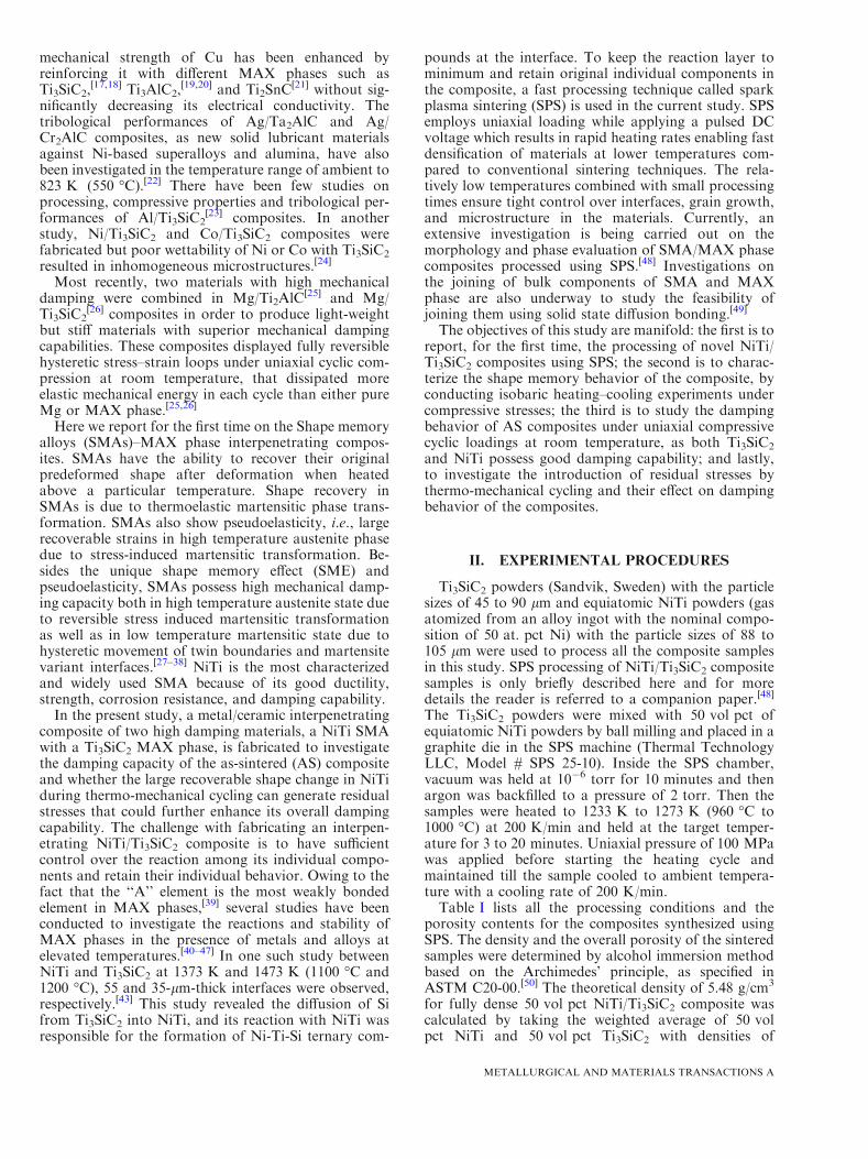
Table I. Processing Conditions of 50 vol pct NiTi/Ti3SiC2 Composites and Their Porosity Values
SampleSintering Temperature
[K (�C)] Time (min) Pressure (MPa)Total Porosity
(Vol pct)
SPS # 1 1233 (960) 8 100 16.7 ± 1.1SPS # 2 1233 (960) 20 100 16.5 ± 0.8SPS # 3 1253 (980) 10 100 16.4 ± 1.1SPS # 4 1273 (1000) 3 100 17.2 ± 0.9
METALLURGICAL AND MATERIALS TRANSACTIONS A

followed by cyclic compression tests to determine energydissipation of TC composites. The compression axis inall the experiments was perpendicular to the loadingdirection in the SPS.
III. RESULTS AND DISCUSSION
A. Microstructural Characterization and CalorimetricAnalysis
Back scattered electron (BSE) images of the SPS # 2samples are shown in Figure 1. The low magnificationimage in Figure 1(a) shows the distribution of differentphases present in the composite. The composition of thelight gray phase and the dark phase in Figure 1(a) isdetermined by EDS analysis which is equiatomic NiTiand Ti3SiC2 phase, respectively. Figure 1(a) clearlydemonstrates that the two main phases, NiTi andTi3SiC2, present in the composite are truly interpene-trating. Figure 1(b) shows higher magnification imageof the interface between NiTi and Ti3SiC2 phase. Onfurther increasing the magnification, a sub-micronreaction layer is observed and the reaction phases inthe interface are confirmed to be Ti2Ni, Ti5Si3, andNiTiSi by electron backscattered diffraction (EBSD)analysis reported in the companion paper.[48]
Figure 2 shows a typical DSC curve of the NiTi/Ti3SiC2 (SPS # 3) composite. The presence of peaks inthe DSC curve suggests martensitic phase transforma-tion in the NiTi phase of the SPS # 3 composite. Areaunder the cooling (heating) peak represents the enthalpyof transformation from austenite to martensite (respec-tively, martensite to austenite). As the enthalpy oftransformation is the amount of energy required for thetransformation per gram of the composite, it is possibleto obtain the weight and volume fraction of thetransformable NiTi phase present in the composite bycomparing it with the enthalpy of pure NiTi using theEqs. [1] to [3] below.
WNiTi ¼ DHcomp:
DHNiTi� 100; ½1�
WTi3SiC2 ¼ 100�WNiTi; ½2�
VNiTif ¼
WNiTi=qNiTi� �
WNiTi=qNiTið Þ þ WTi3SiC2=qTi3SiC2ð Þ½ �� 100� Poverallð Þ:
½3�
WNiTi is the wt pct of NiTi, WTi3SiC2 is the wt pct ofTi3SiC2 in the composite, DHcomp. is the enthalpy oftransformation of the composite, DHNiTi is the enthalpyof transformation of pure equiatomic bulk NiTi, Vf
NiTi isthe volume fraction of NiTi (vol pct) in the composite,qNiTi is the theoretical density of NiTi, qTi3SiC2 is thetheoretical density of Ti3SiC2, Poverall is volume fractionof overall porosity (vol pct) in the composite.Table II lists the values of the transformation tem-
peratures (Ms: Martensite start and Af: Austenite finish,
Fig. 1—Back scattered electron (BSE) images of NiTi/Ti3SiC2 composite processed at 1233 K (960 �C), 20 min, 100 MPa; (a) low magnificationimage of the composite showing distribution of NiTi (bright phase) and Ti3SiC2 (gray phase) in the composite, (b) high magnification image ofthe interface between NiTi and Ti3SiC2 phase.
Fig. 2—Differential scanning calorimetry (DSC) curve clearly show-ing the transformation in the SPS # 3 composite. It also depicts themethod for determining the transformation temperatures.
METALLURGICAL AND MATERIALS TRANSACTIONS A

directly determined from the DSC curve shown inFigure 2), the enthalpy of transformation (DHAfiM), theweight, and volume percent of the transformable NiTiphase for all the composite samples. The table alsocompares their transformation temperatures and en-thalpy values to that of pure equiatomic bulk NiTi. Aslight decrease is observed in the transformationenthalpy (DHAfiM) of the composite as the sinteringtemperature is increased from 1233 K to 1253 K(960 �C to 980 �C). However, a sharp decrease intransformation enthalpy is evident when the sinteringtemperature is increased to 1273 K (1000 �C) eventhough the sintering time is reduced to only 3 minutes.As the NiTi is the only transformable phase in thecomposite, the enthalpy has a direct correlation to theamount of NiTi transforming in the composite. SPS # 4has the lowest and SPS # 1 has the highest amount oftransformable NiTi present in the composite. This isassuming that the new reaction phases formed do nottransform.Calculation of the volume fraction of the transform-
able phase is based on the assumption that weight andvolume fraction of the reaction phases is small ascompared to individual NiTi and Ti3SiC2 phases. Theobserved vol pct of the transformable NiTi in thecomposite is 10 to 18 pct less than that of startingpowders of the composite which had 50 vol pct NiTi.Possible explanations for lower volume percentage oftransformable NiTi are: (a) the consumption of someNiTi by the reaction with Ti3SiC2 during sinteringleading to the formation of new non-transformingphases such as Ti2Ni, Ti5Si3, and NiTiSi at the inter-face;[48] (b) formation of Ti2Ni precipitates in NiTi dueto the Ni diffusion towards the interface with Ti3SiC2,and (c) the presence of dislocation density which canpartially inhibit transformation. It has been reportedearlier that cold work or presence of high dislocationdensities can be the reason for non-transformingNiTi.[54,55] The investigations on NiTi/TiC compositesreported that not all the NiTi present in the compositestransforms.[54] In the current study, the composites arecooled from sintering temperatures to room temperatureunder 100 MPa stress. Residual stresses created bythermal expansion mismatch and the transformationstrains under 100 MPa stress may get relieved throughthe formation of dislocations, thus reducing the amountof transforming NiTi phase. The fact that the transfor-mation temperatures observed in NiTi/Ti3SiC2 compos-ites are close to that of equiatomic NiTi eliminates thepossibility of compositional changes being the reason ofnon-transforming NiTi in the composites (Table II). Allthe NiTi/Ti3SiC2 composites show similar transforma-tion temperatures and temperature hysteresis (DT =Af � Ms).
B. Thermo-mechanical Cycling of As-sintered (AS) SPS# 3 Composite
The aim here is to investigate whether the compositesshow reversible shape change or not, and how it isaffected by the magnitude of applied stress. One of thegoals of this work is also to evaluate energy dissipationT
able
II.
Summary
oftheDSC
Resultsfor50volpct
NiTi/Ti 3SiC
2Composites,TheirTransform
ationTem
peraturesandEnthalpies,andtheAmountofTransform
ingPhase
in
theComposite
Sample
Name
EnthalpyofTransform
ation,
Austeniteto
Martensite,
(DH
AfiM)(J/g)
Martensite
Start
(Ms)[K
(�C)]
AusteniteFinish
(Af)[K
(�C)]
DT=
Af�
Ms
[K(�C)]
Wtpct
ofthe
Transform
able
NiTiPhase
intheComposite
Volpct
oftheTransform
able
NiTiPhase
intheComposite*
SPS#1
17.6
347(74)
383(110)
36(36)
57.7
40.6
SPS#2
17.5
346(73)
381(108)
35(35)
57.4
40.5
SPS#3
17.5
344(71)
377(104)
33(33)
57.4
40.5
SPS#4
14.6
344(71)
377(104)
33(33)
47.4
32.0
Pure
NiTi(bulk)
30.5
351(78)
387(114)
36(36)
——
*Initialpowder
mixture
(before
sintering)contained
50volpct
oftransform
able
NiTi.
METALLURGICAL AND MATERIALS TRANSACTIONS A
potential of the novel NiTi/Ti3SiC2 composites andunderstand the effect of thermo-mechanical treatmenton the energy dissipation in the composites rather thanto optimize the processing conditions.
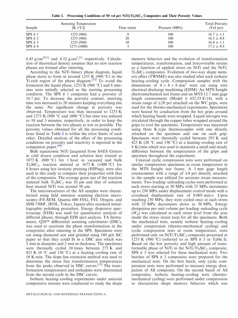
Figure 3 shows a detailed flowchart of thermal cyclingunder uniaxial compressive stresses for the SPS # 3composite. To begin with, a minimum constant stress of10 MPa is applied during thermal cycling to accuratelymeasure strain changes due to the transformation in theNiTi phase of the composite. Stress is increased incre-mentally to 50, 75 100, 150, and 200 MPa in theaustenite phase and at each stress, the composite isthermally cycled once from the austenite to martensitephase and back, in order to obtain its stress–tempera-ture relationship. At the end of thermal cycle at each ofthe 100, 150, and 200 MPa stresses, the composite isunloaded to 10 MPa in the austenite phase and ther-mally cycled once to study the evolution of TWSMEwith prior thermo-mechanical treatments. The thermalcycling at different stresses is performed on the samespecimen. Bulk pure equiatomic NiTi is also subjectedto the same thermal history for meaningful comparisonwith the SPS # 3 composite.
1. One-way shape memory effectFigures 4(a) and (b) show strain versus temperature
plots under increasing compressive stresses for the SPS #3 composite and pure NiTi, respectively. The 75 MPastress cycle in both the composite and the NiTi isomitted for clarity. It is observed that important shapememory characteristics such as transformation temper-atures, transformation, and irrecoverable strains changeas a function of stress for both the composite and bulkNiTi. These are analyzed in detail in the followingsections. Figure 5(a) includes a schematic showing themethod for measuring transformation temperatures,
transformation, and irrecoverable strains in the NiTiand the composite.
a. Evolution of transformation temperatures with stress.Stress–temperature plots of the SPS # 3 composite andpure NiTi are shown in Figure 5(b). Owing to the factthat martensitic transformation involves shear deforma-tion, application of stress assists in the martensitictransformation. This leads to the shift of martensitictransformation temperatures to higher values underexternal stresses. Pure NiTi nicely follows this trend asboth the austenite (martensite) start, As (Ms), andaustenite finish, Af, temperatures are shifted by almostthe same amount at each stress value.For the SPS # 3 composite, Ms and Af are shifted to
higher values whereas Mf and As remain almost thesame or are slightly lowered, as compared to those ofpure NiTi under the same external stress level. This shiftin transformation temperatures leads to the broadeningof the transformation ranges (i.e., Af � As andMs � Mf) at each stress. The most probable reason forthe observed increase in Ms and Af values in thecomposite is the creation of local stress concentrationsdue to porosity and non-transforming reaction phases atthe interface between NiTi and Ti3SiC2. These stressconcentrations lead to early initiation of forward andreverse transformation in the composite as compared topure NiTi.There are two reasons that can lead to lowering of Mf
and As temperatures when compared with unreinforcedNiTi. First, the presence of non-transforming ceramicregions around the NiTi can cause a back stress due tothe volume and shape mismatch when the martensiteplates nucleate and propagate, thus requiring higherdriving force to finish the transformation.[54,56] Reori-entation/detwinning cannot be completed because of thepresence of constraints and thus the reverse transfor-mation is easier which leads to reduction in As. It is well-known in SMAs that the As temperature of reoriented/detwinned martensite is notably higher than that oftwinned martensite. Moreover, the stiffness of the NiTiphase is further lowered during the transformation, thusdecreasing the stress experienced by the NiTi phase.[57]
This may lead to a decrease (respectively, increase) in theforward (respectively, reverse) transformation finishtemperatures. Numerous other investigations have alsoreported a decrease inMf and As.
[58,59] The lowerMf andAs values as compared to pure NiTi are also inagreement with the earlier reported observations onNiTi/TiC composites where TiC was added as areinforcement of up to 20 vol pct.[54,56] However, theincrease in Ms and Af values does not agree with theobserved behavior in NiTi/TiC composites[54,56] and thatpredicted by micromechanical modeling of SMA-cera-mic composites.[57] The difference lies in the nature ofthe SPS # 3 composite, which is interpenetrating andcontains some residual porosity and reaction layers,whereas in the aforementioned studies,[54,56,57] the dis-crete reinforcements added has a maximum volumefraction of 20 pct with little or no porosity and reactionlayers.
Heated from room temperature to 423 K (150
°C) to austenite phase under a minimum (~10 MPa) stress
Thermal cycling from austenite to martensite and back (1 cycle) under the minimum (~10 MPa) stress
Increased stress to 50, 75 and 100 MPa in austenite and cycled once
Reduced stress to 10 MPa and cycled once
Increased stress to 150 and 200 MPa, subsequently and cycled once
Reduced stress to 10 MPa in austenite and cycled once
Stopped
Fig. 3—Flowchart of thermal cycling under compressive stresses forSPS # 3 composite and pure equiatomic NiTi. All the cycles at dif-ferent stresses are on the same sample.
METALLURGICAL AND MATERIALS TRANSACTIONS A

b. Evolution of transformation and irrecoverable strainswith stress. In SMAs which show only one-way shapememory effect, when the austenite is cooled below Mf
temperatures under almost zero stress, austenite trans-forms into martensite with several possible variants withno notable macroscopic shape change. The structurethus obtained is referred to as ‘‘self-accommodated’’martensite since the different variants form to minimizethe shape change and thus the energy. When the self-accommodated martensite is stressed at constant tem-perature, some variants grow at the expense of othersand form a single variant martensite. This process iscalled martensite reorientation or detwinning and isalways accompanied by macroscopic shape change.When SMAs are cooled under low stresses fromaustenite to martensite, both twinned and detwinnedmartensite are formed accompanied by macroscopicshape change. As the stresses are increased, more ofdetwinned martensite forms and higher transformation
strains are observed. The transformation strains increasewith the applied stresses for pure NiTi and SPS # 3composite as shown in Figure 6(a). Smaller transforma-tion strains are observed in SPS # 3 composite ascompared to pure NiTi due to the following reasons:first, the SPS # 3 composite has less than 50 vol pct ofpure transformable NiTi; secondly, the stress experi-enced by the NiTi phase in the composite is less than theapplied external stress because the stiffer Ti3SiC2 phasecarries most of the stress; and lastly, the Ti3SiC2 phaseputs a constraint on the amount of detwinning occurringby not allowing the martensite to detwin in order tomaintain the compatibility across the interfaces.Irrecoverable strains in SMAs are usually caused by
generation and motion of dislocations (transformationinduced plasticity) and remnant martensite that does nottransform back to austenite even after heating aboveAf (retained martensite). Thus, irrecoverable strains
Fig. 4—Strain versus temperature plots under increasing compressivestresses for (a) SPS # 3 composite, and (b) equiatomic bulk NiTi.
Fig. 5—(a) Schematic depicting the method used for measuringtransformation temperatures and transformation and irrecoverablestrains of NiTi and composites, and (b) evolution of the transforma-tion temperatures with increasing compressive stresses (Clausius–Cla-peyron plot) for SPS # 3 composite (solid lines) and its comparisonwith that of bulk NiTi (dotted lines).
METALLURGICAL AND MATERIALS TRANSACTIONS A

increase on increasing the applied stresses due to highertransformation induced plasticity and amount ofretained martensite, as observed in Figure 6(a). Inter-estingly, the irrecoverable strains for the SPS # 3composite are very close to that of pure NiTi, evenafter having large difference in the transformationstrains, at each stress value. The ratio of the irrecover-able to transformation strains of the SPS # 3 compositeand pure NiTi at each stress provides a better compar-ison for the reversibility of the martensitic transforma-tion in the composite and the pure NiTi (Figure 6(b)).This ratio is much higher for the SPS # 3 composite thanthat of pure NiTi which suggests that more factors arecontributing towards the irrecoverable strain in the SPS# 3 composite than those mentioned above for pureSMAs (NiTi). Irrecoverable strain in the composite is
arguably a sum of two contributions: irrecoverablestrain in NiTi and irrecoverable strain in Ti3SiC2.Irrecoverable strain in NiTi can be further categorizedinto two parts: one caused by dislocations and retainedmartensite in NiTi, irrespective of the presence ofTi3SiC2 around it; second caused by generation ofdislocations and retained martensite due to the presenceof Ti3SiC2 in the NiTi region, especially closer to theinterface between NiTi and Ti3SiC2. Irrecoverable strainin Ti3SiC2 could be due to dislocation glide in individualgrains and their bending or kinking. Some of theirrecoverable strain in Ti3SiC2 can possibly come fromdelamination, that does not propagate, but remainscontained within the grain.During the transformation from austenite to mar-
tensite, high local strains and thereby high local stressesare generated due to the geometric constraints imposedby the Ti3SiC2 phase. Stresses as high as 700 MPa havebeen reported in the literature when SMA is preventedfrom returning to high temperature phase upon heatingdue to external constraints.[60] These high stressescoupled with local stress intensity factors induced bypores and voids can generate very high local stressescausing deformation of Ti3SiC2. In fully dense Ti3SiC2,deformation is completely reversible up to 1 GPa stressunder compressive loadings at room temperature.[14]
However, the presence of porosity in the composite maycause irrecoverable deformation in Ti3SiC2 at lowerstresses than mentioned above, thus contributing to thetotal irrecoverable strain of the SPS # 3 composite. It isdifficult to estimate quantitative contributions of eachfactor at this time and specially designed experimentsand/or finite element modeling are needed to estimatethem.
2. Two-way shape memory effect (TWSME)Figures 7(a) and (b) show the two-way shape memory
strain versus temperature plots for the SPS # 3 com-posite and pure equiatomic NiTi, respectively. Firstly,the AS SPS # 3 composite is thermally cycled underminimum stress (10 MPa) to determine whether theresidual stresses generated during cooling from thesintering temperatures are sufficient to cause transfor-mation. No significant TWSM strain is detected in thecomposite. As previously described, to investigate theformation of internal stress and study its evolution, theSPS # 3 composite is thermally cycled once underminimum stress (10 MPa) after cycling each at 100, 150,and 200 MPa stress. Transformation strains obtainedduring thermal cycling at 100, 150, and 200 MPastresses and two-way shape memory (TWSM) strainsobtained under minimum stress after cycling at thesestresses are compared for the SPS # 3 composite andpure equiatomic NiTi in Figure 8(a). CompressiveTWSM strains are observed for both the SPS # 3composite and the NiTi and are found to increase withstress, similar to transformation strains.In TWSME, austenite directly transforms to a mix-
ture of twinned and detwinned martensite depending onthe intensity of internal stresses even when no externalstress is applied and this transformation is accompaniedby corresponding macroscopic shape change. In
Fig. 6—(a) Evolution of the transformation (solid symbols) and irre-coverable (open symbols) strains with increasing compressive stressesfor SPS # 3 (blue color) composite and its comparison with that ofpure NiTi (red color), and (b) comparison of the ratio of irrecover-able to transformation strains of SPS # 3 composite with that ofpure NiTi at different compressive stresses.
METALLURGICAL AND MATERIALS TRANSACTIONS A

TWSME, one of the several possible variants in mar-tensite is favored due to the directional nature ofinternal stresses in the SMA. Plastic deformation ofmartensite leading to directional arrangement of dislo-cations or retained martensite due to prior thermo-mechanical treatment is one of the several mechanismsthat can cause generation of directional internal stressesin SMAs.[61–63] As the stress under which the samplesare cycled is increased, further dislocation storageoccurs leading to more plastic deformation of martensiteand more retained martensite in austenite, consequentlyhigher internal stresses and TWSM strains are obtainedas shown in Figure 8(a).
Lower TWSM strains in the SPS # 3 composite areobtained as compared to pure NiTi after thermal cyclingat same stresses. This is due to the fact that thecomposite shows lower transformation strains as theamount of transformable NiTi and the stress experi-enced by the NiTi phase in the composite is less than
that in bulk NiTi. Similar to irrecoverable and trans-formation strain comparison described in the previoussection, the ratio of the TWSM to transformation strainof the SPS # 3 composite and pure NiTi at each stressprovides a better comparison (Figure 8(b)). This ratio ismuch lower for the SPS # 3 composite than that of pureNiTi, which indicates that the formation of directionalinternal stresses is hindered by the presence of theTi3SiC2 phase.
C. Energy Dissipation in NiTi/Ti3SiC2 Composites
Both the AS and TC SPS # 3 composites, show fullyreversible, closed, non-linear hysteretic stress–strainloops when loaded in compression. During cyclicloading with increasing maximum stress, the first loopis always slightly open while the second loop is closed.
Fig. 7—Evolution of two-way shape memory effect (TWSME) withincreasing compressive bias stresses during prior thermo-mechanicalcycling for (a) the SPS # 3 composite, and (b) equiatomic bulk NiTi.
Fig. 8—(a) Evolution of the transformation and two-way shapememory (TWSM) strains with increasing compressive stresses for theSPS # 3 composite and its comparison with that of pure NiTi, and(b) comparison of the ratio of TWSM strain obtained at 10 MPa totransformation strain of the SPS # 3 composite with that of pureNiTi after cycling at same stresses of 100, 150, and 200 MPa.
METALLURGICAL AND MATERIALS TRANSACTIONS A

This behavior, typical for pure MAX phases,[26] is alsoobserved in bulk NiTi in martensite. During cyclicloading with decreasing maximum stress, all the loops atand below 200 MPa are closed for both the composites(AS and TC) and their individual constituents (NiTi andTi3SiC2). Wd, energy dissipation per unit volume perloading–unloading cycle, is calculated at each peakstress by measuring the area inside the stress–strainloops. Energy dissipation is calculated only from thefully reversible, closed hysteretic loops during cyclicloading from decreasing maximum stress. Figure 9shows one representative engineering stress–strain loopat 200 MPa for each material, namely fully dense pureTi3SiC2, pure NiTi, TC pure NiTi, AS, and TC SPS # 3composites. The energy dissipation is the highest for theTC composite followed by AS composite, pure NiTi, TCpure NiTi, and fully dense pure Ti3SiC2. To compare theenergy dissipation capacity at varying stress levels fordifferent materials, the energy dissipation (Wd) is plottedas a function of maximum stress squared in Figure 10.For pure Ti3SiC2 phases, a linear dependence of Wd onr2 is predicted and experimentally observed where r isthe maximum applied stress.[15] On plotting Wd as afunction of r2 for the pure NiTi and NiTi/Ti3SiC2 SPS #3 composites, a linear dependence is observed where allthe straight lines have an R2 value> 0.96 except forpure NiTi which has a value of 0.91. As shown inFigure 10, the highest slope and thereby the highestdissipation, (Wd), is observed at all stress values for theTC composite followed by AS composite. Pure NiTi andTC pure NiTi have similar dissipation and Wd is thelowest for pure Ti3SiC2. At 200 MPa applied stress, Wd
in the TC composite is 18 times larger than that of finegrain (FG) fully dense pure Ti3SiC2 and 3 times largerthan pure NiTi. In AS composite, Wd is 13 times largerthan that of FG fully dense pure Ti3SiC2 and 2 timeslarger than that observed in pure NiTi. Among all theworks on the metal/MAX composites in the literature,
energy dissipation has only been reported in Mg/Ti3SiC2
composites at stresses below 200 MPa.[26] Both the TCand AS composites of the present study show higher Wd
than Mg/Ti3SiC2 composites at similar stresses. Wd inthe TC composites is higher by an order of magnitudewhen compared to Mg/Ti3SiC2 composites at similarstresses.
1. Damping in as-sintered (AS) compositesThe major contributing factors for the high energy
dissipation observed in the SPS # 3 composite are thedamping contributions from pure Ti3SiC2, pure NiTiaway from the interface, and in regions of NiTi closer tothe interface between NiTi and Ti3SiC2 phases, and thepresence of porosity. MAX phases in general andTi3SiC2 in particular are known to be good dampingmaterials. As stated earlier, Ti3SiC2 dissipates 25 pct(0.7 MJ/m3) of the mechanical energy while beingcompressed to 1 GPa stress at room temperature.[14]
The high energy dissipation in the MAX phases is due tothe reversible formation and annihilation of IKBsduring loading–unloading cycles.[14] As Ti3SiC2 is thestiffer phase in the SPS # 3 composite, it carries most ofthe stress. Thus, the stress experienced by Ti3SiC2 ishigher than the applied external stress, which leads tohigher damping contribution of the Ti3SiC2 phase to theoverall damping of the composite.In addition, SMAs are also known to be high
damping materials in both, austenite and martensitestate. In the current study, all the mechanical cyclingexperiments aimed at measuring energy dissipation areperformed at room temperature, at which equiatomicNiTi is in martensite state. The damping in martensite isdue to hysteretic movement of twin boundaries andinterfaces between the different variants, the latter foundto be a necessary requirement for high damping.[64]
Moreover, microstructural features in martensite platessuch as dislocations, stacking faults, and other defects
Fig. 9—Engineering stress–strain loops at 200 MPa for each mate-rial, namely pure NiTi, fully dense pure Ti3SiC2, thermo-mechani-cally cycled (TC) pure NiTi, as-sintered (AS), and TC SPS # 3composites.
Fig. 10—Energy dissipation per unit volume per loading–unloadingcycle (Wd) as a function of maximum applied stress squared for eachmaterial, namely pure NiTi, fully dense pure Ti3SiC2, thermo-mechanically cycled (TC) pure NiTi, as-sintered (AS), and TC SPS #3 composites.
METALLURGICAL AND MATERIALS TRANSACTIONS A

also contribute to high damping of SMAs.[30] Althoughthe stress experienced by NiTi is lower than theexternally applied stress to the composite, twinninghas been experimentally observed using neutron diffrac-tion in pure NiTi at stresses as low as 33 MPa.[65]
Another important contributing factor for dampingin the composites which is not present in pure bulk NiTior Ti3SiC2 phases is the damping caused by the twinsand twin boundaries possibly formed due to the residualstress relaxation occurring in the interface between theNiTi and Ti3SiC2 phases. On cooling the compositesfrom sintering temperatures, elastic and thermal mis-match caused by the differences in the elastic modulusand thermal expansion coefficients, respectively, be-tween Ti3SiC2 phase and NiTi could lead to thegeneration of residual stresses in the interface. Addi-tional mismatch stresses could be generated betweenNiTi and Ti3SiC2 phases due to volumetric and shapechanges upon transformation in NiTi. These stressesmay get relaxed by the formation of relaxation twins inthe NiTi regions near the interface. Several studies onmetal matrix composites (MMCs) reinforced withceramic fibers suggest that interface thermal stressespromote the formation of highly mobile dislocationzones in the metal matrix near the interfaces.[66,67] InNiTi, stress for twin formation is lower than stress forformation of dislocations. Hence, in the SPS # 3composite, more relaxation twins are expected to formthereby contributing to the overall energy dissipation ofthe composite. For multiphase materials such as MMCsreinforced with ceramic fibers, a model has beendeveloped and supported with experimental results,which divides the contributions to overall damping intothree parts: the fibers, the matrix far from the fibers, andthe high dislocation density zones, also called micro-plastic zones, around the fibers.[68] This aforementionedmodel for multiphase materials substantiates the argu-ment that interface region in the SPS # 3 composite is acontributing factor to its overall damping. As the NiTiand Ti3SiC2 phases are present in equal volume fractionsin the SPS # 3 composite, contribution due to interfacetwinning towards overall damping cannot be neglected.
It is quite well-known that the higher the percentageof the porosity in the MAX phase, the higher the energydissipation (Wd) gets as compared to a fully dense MAXphase.[69,70] Porosity reduces the threshold stress forkink band formation which is an effect of reduction inshear moduli.[69] It has been shown that 18 pct porosityin FG pure Ti3SiC2 leads to an increase in the energydissipation (Wd) by a factor of 6 at a stress of 200 MPawhen compared to a FG fully dense Ti3SiC2.
[69] In thecurrent study, the SPS # 3 composite has 16.4 pctoverall porosity mostly due to incomplete sintering ofMAX phase. Thus, it is only fair to argue that 16.4 pctporosity in the SPS # 3 composite enhances thedissipation capacity several folds and thereby signifi-cantly increases the overall damping capacity of thecomposite.
In summary, four factors that result in an increase inthe damping observed in the AS NiTi/Ti3SiC2 compositeas compared to pure individual constituents are: first,higher stresses experienced by the Ti3SiC2 phase due to
difference in elastic moduli of the NiTi and Ti3SiC2
phases present in the composite which leads to higherdamping in the Ti3SiC2 phase; second, damping due tohysteretic movement of twins and twin boundaries inNiTi phase; third, newly formed twins and twin bound-aries in the NiTi near the interface region due torelaxation of residual stresses in the composite; andlastly the presence of porosity in the composite. As ofnow, it is difficult to comment on the quantitativecontributions of each of the four possible factors to theoverall damping of the composite.
2. Damping in thermo-mechanically cycled (TC)compositesThermo-mechanical cycling leads to the generation of
internal stresses, as observed in the form of TWSME inthe SPS # 3 composite. This internal stress in turn leadsto the reduction in the stress required for detwinning.Hence, when an external stress of, for example,200 MPa is applied, more twin boundaries move inTC than AS composites leading to higher energydissipation, Wd, in TC than AS composites. As previ-ously stated, irrecoverable strain in the SPS # 3composite is due to the generation of dislocations inthe bulk NiTi and in the regions near the interface alongwith irrecoverable strain in Ti3SiC2 phase. Dislocations,twins, and other defects near the interface region createddue to thermo-mechanical cycling may affect the overallenergy dissipation capability of the composite. It hasbeen shown that interaction of dislocations with otherlattice defects could influence the energy dissipationcapacity.[71] Also, several studies observed a correlationbetween the damping capacity and generation andmotion of dislocations around the interfaces betweenmultiphase materials.[68,72] The nature of interaction ofthese defects with Ti3SiC2 phase which itself showsreversible kinking behavior while loading is not clear atthis time. The dislocations and other defects formed dueto thermo-mechanical cycling coupled together with thereasons listed in the AS NiTi/Ti3SiC2 composite result inan increased damping in the composite as compared topure constituents.To the best of the authors’ knowledge, both the TC
and AS NiTi/Ti3SiC2 composites show higher energydissipation, Wd, than all the metal/MAX compositesreported in the literature to date, up to 200 MPa stress.Also, Wd in TC composites is higher by almost an orderof magnitude when compared to Mg/Ti3SiC2 compos-ites at similar stresses.[26] In summary, the novel SMA/MAX phase composites show promising properties as ahigh damping material at low stresses and the presentwork highlights the ability to enhance the performancewith suitable thermo-mechanical loading paths.
IV. SUMMARY AND CONCLUSIONS
In the present work, for the first time, a novel shapememory alloy/MAX phase composites has been pro-cessed using spark plasma sintering. Thermo-mechani-cal response and damping behavior of NiTi/Ti3SiC2
METALLURGICAL AND MATERIALS TRANSACTIONS A
composites has been studied in detail. The majorfindings of this work are as follows:
1. Microstructural characterization via scanning elec-tron microscopy clearly depicted the presence oftwo distinct, interconnected phases, NiTi, and Ti3-SiC2, along with some remnant porosity in the com-posites. Martensitic transformation in NiTi/Ti3SiC2
composites is confirmed by the transformationpeaks observed using DSC. One-way and TWSMEsare observed in the composites during thermo-mechanical characterization.
2. The stress–temperature phase diagrams of the com-posites are analyzed and compared to those of pureNiTi. For the composite, Ms and Af are shifted tohigher values whereas Mf and As stayed the sameor are shifted to slightly lower values, as comparedto pure NiTi, at each stress. The increase in the Ms
and Af is due to the creation of local stress concen-trations when external load is applied as a result ofporosity and non-transforming reaction phases atthe interface between NiTi and Ti3SiC2. Loweringof Mf and As is attributed to two factors: firstly,the presence of non-transforming ceramic regionsaround the transforming NiTi may cause a backstress due to deformation mismatch when the mar-tensite plates propagate, thus requiring higher driv-ing force to finish the transformation. Secondly, thestiffness of the NiTi phase is lowered during thetransformation, thus decreasing the stress experi-enced by the NiTi phase, leading to a decrease(respectively, increase) in the forward (respectively,reverse) transformation finish temperatures.
3. Transformation and irrecoverable strains in thecomposites show similar trend as observed in pureNiTi; both increase with increasing applied externalstress. However, the ratio of irrecoverable to trans-formation strains of the composite is higher whencompared to that of pure NiTi and the additionalirrecoverable strain is caused because of the con-straints imposed by the Ti3SiC2 phases around thetransforming regions in NiTi and possible deforma-tion of Ti3SiC2 phase (e.g., formation of permanentkink bands).
4. Similar to the one-way effect, increase in TWSMstrain is observed with increase in applied externalstress during prior thermo-mechanical cycling. Theratio of TWSM to transformation strain in thecomposite is lower than that in pure NiTi becausethe presence of Ti3SiC2 interpenetrating regions andthe complex stress state at the interface betweenNiTi and Ti3SiC2 upon transformation prevents theaccumulation of enough directional internal stressesthat lead to TWSME.
5. All the composites show fully reversible, closed,non-linear hysteretic stress–strain loops up to thestress of 200 MPa. The AS NiTi/Ti3SiC2 compositeshows higher energy dissipation than its individualcomponents. At 200 MPa applied stress, the energydissipation measured in the AS composite is 13times larger than FG fully dense pure Ti3SiC2 and2 times larger than pure NiTi. This increase is due
to the following reasons: first, higher stress experi-enced by the Ti3SiC2 phase due to difference in elas-tic moduli of NiTi and Ti3SiC2 phases which leadto higher damping in the Ti3SiC2 phase; second,damping due to hysteretic movement of twins andtwin boundaries in NiTi phase; third, newly formedtwins and twin boundaries in the NiTi phase nearthe interface region due to relaxation of residualstresses in the composite; and lastly, the presence ofporosity.
6. The highest energy dissipation, (Wd), is observed atall stress values for the TC composite followed bythe AS composite. At 200 MPa, the energy dissipa-tion, Wd, in the TC composite is 18 times largerthan FG fully dense pure Ti3SiC2 and 3 times largerthan pure NiTi. The superb energy dissipationcapacity of the composite is attributed to the dislo-cations and other defects formed due to thermo-mechanical cycling leading to more twin boundarymotion in addition to the reasons listed for the AScomposite. At this time, this hypothesis is unsub-stantiated with experimental results and the needfor specially designed experiments and finite ele-ment modeling cannot be overemphasized.
ACKNOWLEDGMENTS
This research was supported by the US Air ForceOffice of Scientific Research (AFOSR), MURI Pro-gram (FA9550-09-1-0686) to Texas A&M University,with Dr. David Stargel as the program manager.
REFERENCES1. M.W. Barsoum: Prog. Solid State Chem., 2000, vol. 28, pp. 201–
81.2. M.W. Barsoum and T. El-Raghy: Am. Sci., 2001, vol. 89, pp. 334–
43.3. M.W. Barsoum, H.I. Yoo, I.K. Polushina, V.Yu. Rud, Yu.V.
Rud, and T. El-Raghy: Phys. Rev. B, 2000, vol. 62, pp. 10194–96.4. T. El-Raghy, M.W. Barsoum, A. Zavaliangos, and S.R. Kalidindi:
J. Am. Ceram. Soc., 1999, vol. 82, pp. 2855–60.5. M.W. Barsoum, T. El-Raghy, and L. Ogbuji: Electrochem. Soc.,
1997, vol. 144, pp. 2508–16.6. J.D. Hettinger, S.E. Lofland, P. Finkel, T. Meehan, J. Palma, K.
Harrell, S. Gupta, A. Ganguly, T. El-Raghy, and M.W. Barsoum:Phys. Rev. B, 2005, vol. 72, pp. 1151201–206.
7. J.M. Schneider, D.P. Sigumonrong, D. Music, C. Walter, J.Emmerlich, R. Iskandar, and J. Mayer: Scripta Mater., 2007,vol. 57, pp. 1137–40.
8. M. Radovic, M.W. Barsoum, T. El-Raghy, and S. Wiederhorn:Acta Mater., 2001, vol. 49, pp. 4103–12.
9. M. Radovic, M.W. Barsoum, T. El-Raghy, J. Seidensticker, andS.M. Wiederhorn: Acta Mater., 2000, vol. 48, pp. 453–59.
10. M. Radovic, M.W. Barsoum, T. El-Raghy, S.M. Wiederhorn, andW.E. Luecke: Acta Mater., 2002, vol. 50, pp. 1297–1306.
11. Z. Sun, Y. Zhou, and M. Li: Corros. Sci., 2001, vol. 43, pp. 1095–109.
12. M.W. Barsoum and M. Radovic: Annu. Rev. Mater. Res., 2011,vol. 41, pp. 195–227.
13. M. Radovic, M.W. Barsoum, A. Ganguly, T. Zhen, P. Finkel, S.R.Kalidindi, and E. Lara-Curzio: Acta Mater., 2006, vol. 54,pp. 2757–67.
METALLURGICAL AND MATERIALS TRANSACTIONS A

14. M.W. Barsoum, T. Zhen, S.R. Kalidindi, M. Radovic, and A.Murugahiah: Nat. Mater., 2003, vol. 2, pp. 107–11.
15. A.G. Zhou, S. Basu, and M.W. Barsoum: Acta Mater., 2008,vol. 56, pp. 60–67.
16. Y. Zhang, Z. Sun, and Y. Zhou: Mater. Res. Innov., 1999, vol. 3,pp. 80–84.
17. Y.C. Zhou, B.Q. Chen, X.H. Wang, and C.K. Yan: Mater. Sci.Technol., 2004, vol. 20, pp. 661–65.
18. Z. Zhang and S. Xu: Rare Met., 2007, vol. 26, pp. 359–64.19. L.M. Peng: Scripta Mater., 2007, vol. 56, pp. 729–32.20. J. Zhang and Y.C. Zhou: J. Mater. Res., 2008, vol. 23, pp. 924–32.21. J.Y. Wu, Y.C. Zhou, and J.Y. Wang: Mater. Sci. Eng. A, 2006,
vol. 422, pp. 266–71.22. S. Gupta, D. Filimonov, T. Palanisamy, T. El-Raghy, and M.W.
Barsoum: Wear, 2007, vol. 262, pp. 1479–89.23. W.J. Wang, V. Gauthier-Brunet, G.P. Bei, G. Laplanche, J.
Bonneville, A. Joulain, and S. Dubois: Mater. Sci. Eng. A, 2011,vol. 530, pp. 168–73.
24. H. Li, L.M. Peng, M. Gong, L.H. He, J.H. Zhao, and Y.F. Zhang:Mater. Lett., 2005, vol. 59, pp. 2647–49.
25. S. Amini, C. Ni, and M.W. Barsoum: Compos. Sci. Technol., 2009,vol. 69, pp. 414–20.
26. S. Amini and M.W. Barsoum: Mater. Sci. Eng. A, 2010, vol. 527,pp. 3707–18.
27. Y. Liu, Z. Xie, and J.V. Humbeeck: Mater. Sci. Eng. A, 1999,vols. 273–275, pp. 673–78.
28. J.V. Humbeeck: J. Alloy. Compd., 2003, vol. 355, pp. 58–64.29. R.R. Hasiguti and K. Iwasaki: J. Appl. Phys., 1968, vol. 39,
pp. 2182–86.30. W. Dejonghe, R. De Batist, L. Delaey, and M. De Bonte: in Shape
Memory Effects in Alloys, J. Perkins, ed., Plenum Press, NewYork, NY, 1975, pp. 451–66.
31. O. Mercier, K.N. Melton, and Y. De Preville: Acta Metall., 1979,vol. 27, pp. 1467–75.
32. Y.T. Huang, G.P. Yang, and P. He: Scripta Metall. Mater., 1985,vol. 19, pp. 1033–38.
33. Y.T. Huang, G.P. Yang, and P. He: Scripta Metall. Mater., 1985,vol. 19, pp. 1039–44.
34. S.K. Wu, H.C. Lin, and T.S. Chou: Acta Metall., 1990, vol. 38,pp. 95–102.
35. K. Iwasaki and R.R. Hasiguti: Trans. Jpn. Inst. Met., 1987,vol. 28, pp. 363–67.
36. W. Dejonghe, L. Delaey, R. De Batist, and J.V. Humbeeck: Met.Sci., 1977, vol. 11, pp. 523–30.
37. H.C. Lin, S.K. Wu, and M.T. Yeh: Metall. Trans. A, 1993,vol. 24A, pp. 2189–94.
38. K. Sugimoto, T. Mori, K. Otsuka, and K. Shimizu: Scripta Metall.Mater., 1974, vol. 8, pp. 1341–48.
39. Y. Zhou and Z. Sun: J. Phys. Condens. Matter, 2000, vol. 12,pp. L457–62.
40. J. Zhang, J.Y. Wang, and Y.C. Zhou: Acta Mater., 2007, vol. 55,pp. 4381–90.
41. T.L. Ngai, W. Zheng, C. Hu, H. Xie, and Y. Li: Adv. Mater. Res.,2011, vols. 211–212, pp. 1051–55.
42. N.F. Gao and Y. Miyamoto: J. Mater. Res., 2002, vol. 17, pp. 52–59.
43. S. Basu, M.F. Ozaydin, A. Kothalkar, I. Karaman, and M.Radovic: Scripta Mater., 2011, vol. 65, pp. 237–40.
44. O. Dezellus, R. Voytovych, A.P.H. Li, G. Constantin, F. Bosselet,and J.C. Viala: J. Mater. Sci., 2010, vol. 45, pp. 2080–84.
45. T. El-Raghy, M.W. Barsoum, and M. Sika: Mater. Sci. Eng. A,2001, vol. 298, pp. 174–78.
46. W.L. Gu, C.K. Yan, and Y.C. Zhou: Scripta Mater., 2003, vol. 49,pp. 1075–80.
47. W.L. Gu and Y.C. Zhou: Trans. Nonferr. Met. Soc. China, 2006,vol. 16, pp. 1281–88.
48. L. Hu, A. Kothalkar, I. Karaman, and M. Radovic: Unpublishedresearch, 2013.
49. A. Kothalkar, A. Cerit, G. Proust, S. Basu, M. Radovic, and I.Karaman: Texas A&M University, College Station, TX (unpub-lished research), 2013.
50. ASTM C20-00: ASTM International, West Conshohocken, PA,2010.
51. Z.G. Wei, R. Sandstrom, and S. Miyazaki: J. Mater. Sci., 1998,vol. 33, pp. 3743–62.
52. J.L. Murray: in Binary Alloy Phase Diagrams, T.B. Massalski(Ed.), 2nd ed., 1990, vol. 3, pp. 2874–76.
53. ASTM F2004-05: ASTM International, West Conshohocken, PA,2004.
54. D. Mari and D.C. Dunand: Metall. Mater. Trans. A, 1995,vol. 26A, pp. 2833–47.
55. H.C. Lin and S.K. Wu: Metall. Trans. A, 1993, vol. 24A, pp. 293–99.
56. K.L. Fukami-Ushiro and D.C. Dunand: Metall. Mater. Trans. A,1996, vol. 27A, pp. 193–203.
57. BT Lester, Y Chemisky, and DC Lagoudas: Smart Mater. Struct.,2011, vol. 20, pp. 094002-1–094002-13.
58. R.J. Salzbrenner and M. Cohen: Acta Metall., 1979, vol. 27,pp. 739–48.
59. A. Hedayat, J. Rechtien, and K. Mukherjee: J. Mater. Sci., 1992,vol. 27, pp. 5306–14.
60. P. Sittner, D. Vokoun, G.N. Dayananda, and R. Stalmans:Mater.Sci. Eng. A, 2000, vol. 286, pp. 298–311.
61. T. Saburi and S. Nenno: Scripta Metall., 1974, vol. 8, pp. 1363–68.62. Y. Liu, Y. Liu, and J.V. Humbeeck: Acta Mater., 1999, vol. 47,
pp. 199–209.63. S. Eucken and T.W. Duerig: Acta Metall., 1989, vol. 37, pp. 2245–
52.64. M. Morin and G. Guenin: J. Phys. Colloq., 1983, vol. 44 (C9),
pp. 247–52.65. S. Rajagopalan, A.L. Little, M.A.M. Bourke, and R. Vaidyanathan:
Appl. Phys. Lett., 2005, vol. 86, pp. 081901–903.66. M. Vogelsang, R. Arsenault, and R. Fisher: Metall. Trans. A,
1986, vol. 17A, pp. 379–89.67. D. Dunand and A. Mortensen: Acta Metall. Mater., 1991, vol. 39,
pp. 127–39.68. E. Carreno-Morreli, S.E. Urreta, and R. Schaller: Acta Mater.,
2000, vol. 48, pp. 4725–33.69. M. Fraczkiewicz, A.G. Zhou, and M.W. Barsoum: Acta Mater.,
2006, vol. 54, pp. 5261–70.70. A.G. Zhou, M.W. Barsoum, S. Basu, S.R. Kalidindi, and T.
El-Raghy: Acta Mater., 2006, vol. 54, pp. 1631–39.71. S. Kustov, S. Golyandin, K. Sapozhnikov, J. Van Humbeeck, and
R. De Batist: Acta Mater., 1998, vol. 46, pp. 5117–26.72. E. Carreno-Morreli: Metall. Mater. Trans. A, 2004, vol. 35A,
pp. 25–35.
METALLURGICAL AND MATERIALS TRANSACTIONS A