thermally-induced birefringence in solid-core photonic crystal fiber lasers
TRANSCRIPT
Q1
123456789
101112131415161718192021222324252627282930313233343536373839404142434445464748495051525354555657585960616263646566
Q3
Optics Communications ∎ (∎∎∎∎) ∎∎∎–∎∎∎
Contents lists available at SciVerse ScienceDirect
Optics Communications
0030-40http://d
n CorrE-m
Pleas
journal homepage: www.elsevier.com/locate/optcom
Thermally-induced birefringence in solid-core photonic crystal fiber lasers
Laleh Mousavi a, Mohammad Sabaeian b,n, Hamid Nadgaran c
a Department of Physics, Dezful Branch, Islamic Azad University, Dezful, Iranb Department of Physics, Faculty of Science, Shahid Chamran University of Ahvaz, Ahvaz, Iranc Department of Physics, College of Science, University of Shiraz, Shiraz 71454, Iran
67
a r t i c l e i n f o
Article history:Received 11 December 2012Received in revised form15 March 2013Accepted 17 March 2013
Keywords:Photonic crystal fibers laserThermal effectsThermally-induced stressesBirefringence
18/$ - see front matter & 2013 Published by Ex.doi.org/10.1016/j.optcom.2013.03.036
esponding author. Tel.: +98 917 310 037 6, faail addresses: [email protected], sabaeia
e cite this article as: L. Mousavi, et a
a b s t r a c t
The authors report photo-thermal effects in solid-core photonic crystal fiber lasers (PCFLs) using a finiteelement method. Thermal stresses and birefringence due to self-heating of PCFLs in the core and thecladding regions were simulated as a function of induced heat per meter. Simulations were devoted tothree kinds of PCFLs with various d/Λ ratios (d is the hole diameter and Λ is the hole-to-hole distance)where large-mode-area solid-core PCFLs with air-holes triangular lattice as cladding and polymercoatings were considered. For thermal modeling, all cooling mechanisms such as convection andradiation have been taken into account. We showed that thermally-induced birefringence has ratherstrong impact on the phase difference between perpendicular polarization components and so ondepolarization.
& 2013 Published by Elsevier B.V.
6869707172737475767778798081828384858687888990919293949596
1. Introduction
High power lasers have been feasible by introducing newoptical devices known as photonic crystal fibers (PCFs) that arebased on wavelength-scale morphological microstructures. PCFs aslow-loss waveguides have been in practical use since 1996 [1,2].PCFs consist of air-holes arranged in a two dimensional triangularpattern running through the whole fiber length. One or more holesare usually missed to create a core surrounded by holey cladding[3,4]. The ratio of the hole diameter (d) to the hole-to-holedistance (Λ) plays a crucial role in determining optical propertiesof PCFs. It has been proved that for a ratio of d/Λo0.45, the one-hole missed PCF can be considered as a single mode fiberregardless of wavelength [3,5,6].
Lasers based photonic crystal fibers have gained much interestdue to their high power operation with considerable stability,excellent beam quality, compactness, and maintenance ease [7,8].A 2.3 m long ytterbium-doped air-clad large-mode-area fiber laserhas been reported delivering 80 W output power equivalent to anaverage output of 35 W/m [9]. High output power of 260 W for a4 m long fiber lasers has also been reported [10]. A drastic outputpower of 1.53 kW has been demonstrated by Bonati et al. by aYb-doped photonic crystal fiber laser (PCFL) [11].
In design and construction of high power PCFLs, one should beaware of detrimental thermal effects which are inevitable espe-cially when the pump power is scaled. Despite large surface to
979899
100
lsevier B.V.
x: +98 61 133 310 [email protected] (M. Sabaeian).
l., Optics Communications
volume ratio of fibers that makes the fibers heat dissipation moreeasily done compared to bulk counterparts, induced heat andconsequently thermal effects are still very much important issuesin high power regimes [12]. An actively cooled fiber laser has beenreported in which a 7 cm short fiber laser with heat load of∼200 W/m was cooled with water [13]. In heavy heat load,thermoelectric coolers are usually preferable [14].
Various PCFLs performance parameters, including beam qual-ity, effective mode area [15], birefringence, and core confinementfactor, are affected by induced heat [15,16]. Also thermal fracture,core melting and thermal lensing limit the power escalationtogether with influences on mode propagation [17] and efficiency.Other thermally affected quantities such as thermally-inducedphase mismatching [18], thermal modal instability [19], anddepolarization loss [4] are also worth noting. In particular, theinfluence of thermally-induced birefringence on laser performancehas been revealed as depolarization loss. Limpert et al. [4] reportedan experimental value of 30% for depolarization loss that is blamedto thermal effects.
The temperature gradient across the PCFLs gives rise torefractive index modifications via two well-known phenomena:thermal dispersion or dn/dT effect and elasto-optics effect as theconsequence of the heat induced stresses [16,20]. Thermal disper-sion and thermally-induced elasto-optics effects alter the mediumrefractive index homogeneously and inhomogeneously, respec-tively. The latter can even convert the scalar refractive index to atensor quantity.
Although there are several good works measuring or calculat-ing the temperature or stresses in PCFs and PCFLs [10,21,22] athorough and comprehensive modeling that includes all other
101102
(2013), http://dx.doi.org/10.1016/j.optcom.2013.03.036i
123456789
101112131415161718192021222324252627282930313233343536373839404142434445464748495051525354555657585960616263646566
676869707172737475767778798081828384858687888990919293
Table 1Thermal, mechanical and optical properties of air and silica.
Property Value Reference
Silica thermal conductivity K 1.37 W/m/K [22]Hard polymer thermal conductivity 0.2 W/m/K [22]Air thermal conductivity 2.58�10−2 [22]Heat transfer coefficient h 10 W/m2/K [14]Silica Young's modulus E 0.73 GPa [34]Hard polymer Young's modulus 1.2 GPa [35]Silica Poisson's ratio ν 0.16 [34]Hard polymer Poisson's ratio 0.452 [35]Silica thermal expansion coeff α 0.51�10−6 [34]Hard polymer thermal expansion coeff 0.8�10−7 [35]Refractive index of doped core n0 n1¼1.4646 [14]Refractive index of undoped silica n2¼1.4572 [14]Refractive index of polymer n3¼1.3827 [14]Laser wavelength λl 1060 nm [14]Perpendicular elasto-optic coefficient B⊥ 27.7�10−12 m2/kg [34]Parallel elasto-optic coefficient Bjj 4.7�10−12 m2/kg [34]
L. Mousavi et al. / Optics Communications ∎ (∎∎∎∎) ∎∎∎–∎∎∎2
thermally related effects such as heat-induced tensor property ofrefractive index and birefringence is missing in the literature;especially, to the best of our knowledge, these important proper-ties have not been analyzed as a function of heat load and d/Λparameters.
This work therefore is devoted to a rigorous analysis ofthermally-induced stresses and birefringence over PCFLs cross-sections via a careful and comprehensive calculation of tempera-ture, temperature gradient and displacement vector components.Our work will focus on thermal effects induced by heat generationinside active cores of PCFLs. Our calculations have been done forPCFLs with d/Λ¼0.18, 0.4 and 0.6 as a function of heat load (W/m)to cover the practical interval of the d/Λ value. Attention has beendrawn to radiation mechanism, a matter which is usually ignoredin the literature for simplicity [20–23]. Almost all approximationsusually employed in the literature will be relaxed. To be precise,the temperature dependence of thermal conductivity; polymercoatings with different thermal, mechanical and optical proper-ties; heat radiation from the fiber surface; and the role of air-holesin thermal and mechanical calculations all have been fully takeninto account.
The results of this work are useful in tuning of cladding-moderesonance in hybrid polymer–silica microstructure optical fibergrating [24], optical birefringence in hybrid MOF [25], dispersionin photonic band gap MOFs [26,27], and tuning of photonic crystalwaveguide microcavity [28]. Also, the applications of this work canbe found in PCF ultrasensitive temperature sensors [29–31].
949596979899
100101102103104105106107108109110111112113114115116117118119120121122123124125126127128129130131132
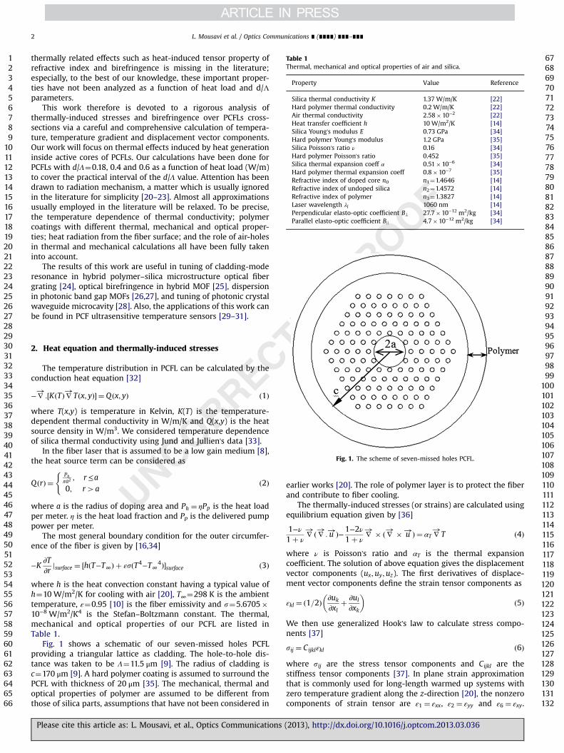
Fig. 1. The scheme of seven-missed holes PCFL.
2. Heat equation and thermally-induced stresses
The temperature distribution in PCFL can be calculated by theconduction heat equation [32]
−∇!
:½KðTÞ∇!Tðx; yÞ� ¼ Q ðx; yÞ ð1Þwhere T(x,y) is temperature in Kelvin, K(T) is the temperature-dependent thermal conductivity in W/m/K and Q(x,y) is the heatsource density in W/m3. We considered temperature dependenceof silica thermal conductivity using Jund and Jullien's data [33].
In the fiber laser that is assumed to be a low gain medium [8],the heat source term can be considered as
Q ðrÞ ¼Phπa2 ; r≤a
0; r4a
(ð2Þ
where a is the radius of doping area and Ph ¼ ηPp is the heat loadper meter. η is the heat load fraction and Pp is the delivered pumppower per meter.
The most general boundary condition for the outer circumfer-ence of the fiber is given by [16,34]
−K∂T∂r
jsurface ¼ ½hðT−T∞Þ þ εsðT4−T∞4Þ�surface ð3Þ
where h is the heat convection constant having a typical value ofh¼10 W/m2/K for cooling with air [20], T∞¼298 K is the ambienttemperature, ε¼0.95 [10] is the fiber emissivity and s¼5.6705�10−8 W/m2/K4 is the Stefan–Boltzmann constant. The thermal,mechanical and optical properties of our PCFL are listed inTable 1.
Fig. 1 shows a schematic of our seven-missed holes PCFLproviding a triangular lattice as cladding. The hole-to-hole dis-tance was taken to be Λ¼11.5 μm [9]. The radius of cladding isc¼170 μm [9]. A hard polymer coating is assumed to surround thePCFL with thickness of 20 μm [35]. The mechanical, thermal andoptical properties of polymer are assumed to be different fromthose of silica parts, assumptions that have not been considered in
Please cite this article as: L. Mousavi, et al., Optics Communications
earlier works [20]. The role of polymer layer is to protect the fiberand contribute to fiber cooling.
The thermally-induced stresses (or strains) are calculated usingequilibrium equation given by [36]
1−ν1þ ν
∇!ð∇!: u!Þ−1−2ν
1þ ν∇!� ð∇!� u!Þ¼ αT ∇
!T ð4Þ
where ν is Poisson's ratio and αT is the thermal expansioncoefficient. The solution of above equation gives the displacementvector components (ux;uy;uz). The first derivatives of displace-ment vector components define the strain tensor components as
εkl ¼ ð1=2Þ ∂uk
∂xlþ ∂ul
∂xk
� �ð5Þ
We then use generalized Hook's law to calculate stress compo-nents [37]
sij ¼ Cijklεkl ð6Þ
where sij are the stress tensor components and Cijkl are thestiffness tensor components [37]. In plane strain approximationthat is commonly used for long-length warmed up systems withzero temperature gradient along the z-direction [20], the nonzerocomponents of strain tensor are ε1 ¼ εxx, ε2 ¼ εyy and ε6 ¼ εxy.
(2013), http://dx.doi.org/10.1016/j.optcom.2013.03.036i

123456789
101112131415161718192021222324252627282930313233343536373839404142434445464748495051525354555657585960616263646566
676869707172737475767778798081828384858687888990
L. Mousavi et al. / Optics Communications ∎ (∎∎∎∎) ∎∎∎–∎∎∎ 3
Under this approximation and for isotropic structure of glassy fiber,the nonzero components of stress are s1, s2, s3ð ¼ szzÞ and s6(see Appendix A). Also, for a glassy medium only three stiffnesscomponents are independent: C11 ¼ Eðν−1Þ=ð2ν2 þ ν−1Þ, C12 ¼−Eν=ð2ν2 þ ν−1Þ, and C44 ¼ E=ðν−1Þ where E is Young's modulus [37].
The complex structure of PCFL does not allow obtaininganalytical solution for PCFL temperature and for thermally-induced stresses (or strains). In calculating the temperaturegradient related quantities, the role of air-holes must be fullyand explicitly taken into account. For this purpose, the finiteelement method was employed to calculate the thermally-induced stress components across the complex structure of PCFs.
Fig. 2(a) and (b) shows sxx and syy distributions over a PCFLcrosssection with a typical value of d/Λ¼0.4 and a heat load ofPh ¼ 6W=m. In our calculations, the free boundary condition for allair-glass borders was used. In Fig. 2(a) and (b), the darker coloredges show the regions with strong stresses. The results showcompressive stress (negative) for the core and the holey claddingwhile the positive stress is seen for the polymer coating. Accordingto Fig. 2(a), the highest value for x-component of thermally-induced stress occurs at the top and bottom of the first holesplaced at right and left sides of the core. For the y-component, thisevent occurs at the right and left of holes placed at the top andbottom of the core.
Fig. 2. Thermally-induced stresses across a PCFL with d/Λ
Fig. 3. (a) sxx and (b) syy in the core region for a PCFL with d/Λ¼0.4 for a h
Please cite this article as: L. Mousavi, et al., Optics Communications
In Fig. 3(a) and (b), to better see the effects of air-holes in thecore, we suppressed the cladding calculations and show thestresses in the core. In these figures, the effects of nearest holesin the core region are obvious. The presence of holes exerts anadditional local compressive stress.
In Figs. 4(a)–(c) and 5(a)–(c), in order to achieve a quantitativeinsight, we have plotted the stress curves along the x-direction inthe core and the regions near the core. Fig. 4(a) shows sxx for threevalues of heat load of Ph ¼ 3 W=m (green), Ph ¼ 6W=m (red) andPh ¼ 9W=m (black) for a PCFL with d/Λ¼0.18. For this case, themaximum compressive stress over the core region is approxi-mately constant and with a heat load of Ph ¼ 9W=m its absolutevalue is ∼36,250 Pa. It then vanishes quickly at the holes bound-aries (assumed to be free) and again increases with its negativesign. For a PCFL with d/Λ¼0.4, Fig. 4(b), firstly the stress is nolonger constant over the core region; secondly the side valleysdecrease in their absolute values. This event is much severe inFig. 4(c), where we have drawn the x-component of thermally-induced stress for a PCFL with d/Λ¼0.6. For this case, the max-imum compressive stress reaches ∼37,500 Pa with a ∼5000 Pachange relative to the flat part.
Close inspection and attention to Fig. 4(a)–(c) shows a commonplateau of sxx in the core region that itself changes its value andshape by increasing the value of d/Λ from 0.18 (Fig. 4(a)) to 0.4
919293949596979899
100101102103104105106107108109110111112113114115116117118119120121122123124125126127128129130131132
¼0.4 and heat load of Ph¼6 W/m: (a) sxx and (b) syy.
eat load of Ph¼6 W/m. The darker (black) zones show strong stresses.
(2013), http://dx.doi.org/10.1016/j.optcom.2013.03.036i

123456789
101112131415161718192021222324252627282930313233343536373839404142434445464748495051525354555657585960616263646566
676869707172737475767778798081828384858687888990919293949596979899
100101102103104105106107108109110111112113114115116117118119120121122123124125126127128129130131132
Fig. 4. The x-component of stress (sxx) along the x-direction for three heat load powers for (a) d/Λ¼0.18, (b) d/Λ¼0.4 and (c) d/Λ¼0.6.
Fig. 5. The y-component of stress (syy) along the x-direction for three heat load powers and for (a) d/Λ¼0.18, (b) d/Λ¼0.4 and (c) d/Λ¼0.6.
L. Mousavi et al. / Optics Communications ∎ (∎∎∎∎) ∎∎∎–∎∎∎4
(Fig. 4(b)) to 0.6 (Fig. 4(c)). Specifically, as the value of d/Λincreases we see build up of a minimum around the core edgeand this minimum is significant since its value reaches 5000 Pa inFig. 4(c).
Please cite this article as: L. Mousavi, et al., Optics Communications
Let us discuss about syy along the x-direction. Fig. 5(a)–(c) showssyy and it clearly shows that the value of syy peak is two timesgreater than that of sxx, reaching ∼750,000 Pa for a PCFL withd/Λ¼0.6 and a heat load of Ph ¼ 9W=m.
(2013), http://dx.doi.org/10.1016/j.optcom.2013.03.036i
123456789
101112131415161718192021222324252627282930313233343536373839404142434445464748495051525354555657585960616263646566
6768697071727374
L. Mousavi et al. / Optics Communications ∎ (∎∎∎∎) ∎∎∎–∎∎∎ 5
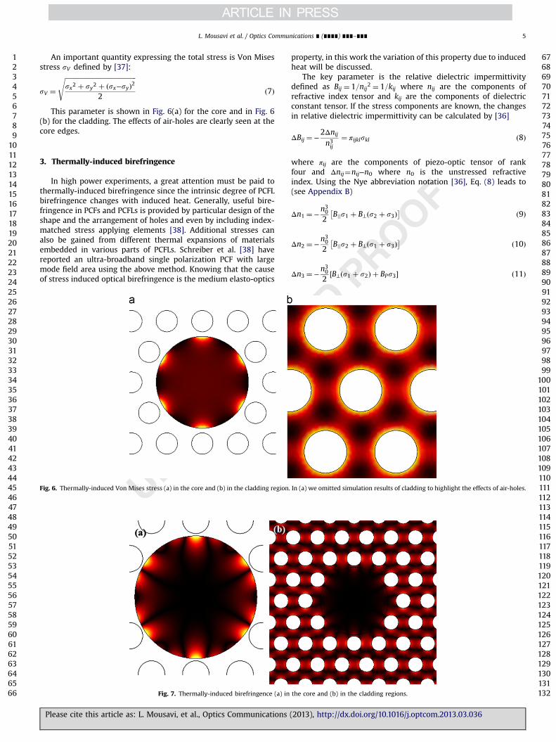
An important quantity expressing the total stress is Von Misesstress sV defined by [37]:
sV ¼ffiffiffiffiffiffiffiffiffiffiffiffiffiffiffiffiffiffiffiffiffiffiffiffiffiffiffiffiffiffiffiffiffiffiffiffiffiffiffiffiffiffiffiffisx2 þ sy2 þ ðsx−syÞ2
2
sð7Þ
This parameter is shown in Fig. 6(a) for the core and in Fig. 6(b) for the cladding. The effects of air-holes are clearly seen at thecore edges.
75767778798081828384858687888990
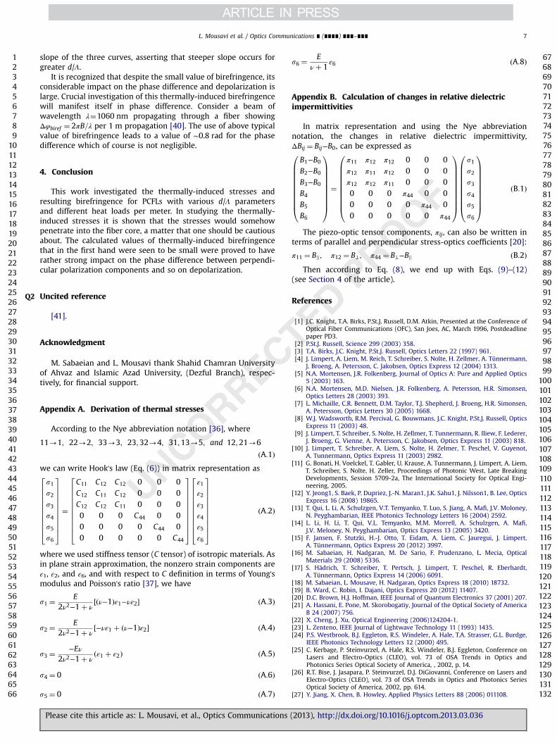
3. Thermally-induced birefringence
In high power experiments, a great attention must be paid tothermally-induced birefringence since the intrinsic degree of PCFLbirefringence changes with induced heat. Generally, useful bire-fringence in PCFs and PCFLs is provided by particular design of theshape and the arrangement of holes and even by including index-matched stress applying elements [38]. Additional stresses canalso be gained from different thermal expansions of materialsembedded in various parts of PCFLs. Schreiber et al. [38] havereported an ultra-broadband single polarization PCF with largemode field area using the above method. Knowing that the causeof stress induced optical birefringence is the medium elasto-optics
Fig. 6. Thermally-induced Von Mises stress (a) in the core and (b) in the cladding region.
Fig. 7. Thermally-induced birefringence (a) in
Please cite this article as: L. Mousavi, et al., Optics Communications
property, in this work the variation of this property due to inducedheat will be discussed.
The key parameter is the relative dielectric impermittivitydefined as Bij ¼ 1=nij
2 ¼ 1=kij where nij are the components ofrefractive index tensor and kij are the components of dielectricconstant tensor. If the stress components are known, the changesin relative dielectric impermittivity can be calculated by [36]
ΔBij ¼ −2Δnij
n3ij
¼ πijklskl ð8Þ
where πij are the components of piezo-optic tensor of rankfour and Δnij¼nij−n0 where n0 is the unstressed refractiveindex. Using the Nye abbreviation notation [36], Eq. (8) leads to(see Appendix B)
Δn1 ¼ −n30
2Bjjs1 þ B⊥ðs2 þ s3Þ� � ð9Þ
Δn2 ¼ −n302
Bjjs2 þ B⊥ðs1 þ s3Þ� � ð10Þ
Δn3 ¼ −n30
2B⊥ðs1 þ s2Þ þ BPs3½ � ð11Þ
919293949596979899
100101102103104105106107108109110111112113114115116117118119120121122123124125126127128129130131132
In (a) we omitted simulation results of cladding to highlight the effects of air-holes.
the core and (b) in the cladding regions.
(2013), http://dx.doi.org/10.1016/j.optcom.2013.03.036i

Q4
123456789
101112131415161718192021222324252627282930313233343536373839404142434445464748495051525354555657585960616263646566
676869707172737475767778798081828384858687888990919293949596979899
100101102103104105106107108109110111112113114115116117118119120121122123124125126127128129130131132
Fig. 8. Thermally-induced birefringence along the x-direction in the core region for (a) d/Λ¼0.18, (b) d/Λ¼0.4 and (c) d/Λ¼0.6.
Fig. 9. Averaged thermally-induced birefringence over the core area as a functionof heat load for three different PCFLs.
L. Mousavi et al. / Optics Communications ∎ (∎∎∎∎) ∎∎∎–∎∎∎6
Δn6 ¼ −n302
B⊥−Bjj� �
s6 ð12Þ
where we used π11 ¼ Bjj, π12 ¼ B⊥ and π44 ¼ B⊥−Bjj where Bjj and B⊥
are the parallel and perpendicular stress-optics coefficients,respectively [20]. If we add the contribution of thermal dispersion,dn/dT effect, we end up with the following formula for eachcomponent:
ΔnTot ¼ΔnTh þ ΔnSt ð13Þwhere ΔnTh ¼ΔTð∂n=∂TÞ and ΔnSt is taken from Eqs. (9)–(12).
The optical birefringence arises from a difference betweenin-plane orthogonal components of refractive index components.Therefore, the thermally-induced birefringence can be calculatedas [37,39]
B¼ n1−n2 ¼ n03
2ðB⊥−BjjÞðs2−s1Þj������
���� ð14Þ
along with its average over the area of interest as
Bav ¼n0
3
2AðB⊥−BjjÞ
Z Zðs2−s1Þdx dy
������� ð15Þ
where A is the core area in the case of average birefringence overthe PCFL core.
Fig. 7(a) and (b) shows the distribution of thermally-inducedbirefringence over the core and the cladding regions, respectively.These figures indicate a rather complicated birefringence in thecore and the holey cladding.
The quantitative plots of thermally-induced birefringence inthe core region are drawn in Fig. 8(a)–(c). For three kinds of PCFLs,four values of heat loads have been used. The results show theeffect of air-holes in the core region. The maximum birefringencefor a heat load of 12 W/m, for example, varies from 1.45�10−8 for
Please cite this article as: L. Mousavi, et al., Optics Communications
d/Λ¼0.18 to 13.5�10−8 for d/Λ¼0.6 that shows an approximatelyone order of magnitude increasing from d/Λ¼0.18 to d/Λ¼0.6.We should note that for conventional fiber laser, even this smallvalue has not been observed [20]. The presence of air-holes causesthis birefringence in PCFL crosssection when the fiber is warmedup. This clearly shows the effects of air-holes in thermal effects offiber lasers.
Fig. 9 compares the average birefringence against the heat loadfor various d/Λ parameters. This figure shows the difference in
(2013), http://dx.doi.org/10.1016/j.optcom.2013.03.036i
Q2
123456789
101112131415161718192021222324252627282930313233343536373839404142434445464748495051525354555657585960616263646566
67686970717273747576
L. Mousavi et al. / Optics Communications ∎ (∎∎∎∎) ∎∎∎–∎∎∎ 7
slope of the three curves, asserting that steeper slope occurs forgreater d/Λ.
It is recognized that despite the small value of birefringence, itsconsiderable impact on the phase difference and depolarization islarge. Crucial investigation of this thermally-induced birefringencewill manifest itself in phase difference. Consider a beam ofwavelength λ¼1060 nm propagating through a fiber showingΔφbiref ¼ 2πB=λ per 1 m propagation [40]. The use of above typicalvalue of birefringence leads to a value of ∼0.8 rad for the phasedifference which of course is not negligible.
77787980818283848586878889
4. Conclusion
This work investigated the thermally-induced stresses andresulting birefringence for PCFLs with various d/Λ parametersand different heat loads per meter. In studying the thermally-induced stresses it is shown that the stresses would somehowpenetrate into the fiber core, a matter that one should be cautiousabout. The calculated values of thermally-induced birefringencethat in the first hand were seen to be small were proved to haverather strong impact on the phase difference between perpendi-cular polarization components and so on depolarization.
90919293
Uncited reference
[41].
949596979899100
Acknowledgment
M. Sabaeian and L. Mousavi thank Shahid Chamran Universityof Ahvaz and Islamic Azad University, (Dezful Branch), respec-tively, for financial support.
101102103104105106107108109110111112113114115116117118119120121122123124125126127128129130131132
Appendix A. Derivation of thermal stresses
According to the Nye abbreviation notation [36], where
11-1; 22-2; 33-3; 23;32-4; 31;13-5; and 12;21-6
ðA:1Þwe can write Hook's law (Eq. (6)) in matrix representation as
s1s2s3s4s5s6
26666666664
37777777775¼
C11 C12 C12 0 0 0C12 C11 C12 0 0 0C12 C12 C11 0 0 00 0 0 C44 0 00 0 0 0 C44 00 0 0 0 0 C44
26666666664
37777777775
ε1
ε2
ε3
ε4ε5
ε6
26666666664
37777777775
ðA:2Þ
where we used stiffness tensor (C tensor) of isotropic materials. Asin plane strain approximation, the nonzero strain components areε1, ε2, and ε6, and with respect to C definition in terms of Young'smodulus and Poisson's ratio [37], we have
s1 ¼E
2ν2−1þ νðν−1Þε1−νε2½ � ðA:3Þ
s2 ¼E
2ν2−1þ ν−νε1 þ ðν−1Þε2½ � ðA:4Þ
s3 ¼−Eν
2ν2−1þ νðε1 þ ε2Þ ðA:5Þ
s4 ¼ 0 ðA:6Þ
s5 ¼ 0 ðA:7Þ
Please cite this article as: L. Mousavi, et al., Optics Communications
s6 ¼E
νþ 1ε6 ðA:8Þ
Appendix B. Calculation of changes in relative dielectricimpermittivities
In matrix representation and using the Nye abbreviationnotation, the changes in relative dielectric impermittivity,ΔBij ¼ Bij−B0, can be expressed as
B1−B0
B2−B0
B3−B0
B4
B5
B6
0BBBBBBBBB@
1CCCCCCCCCA
¼
π11 π12 π12 0 0 0π12 π11 π12 0 0 0π12 π12 π11 0 0 00 0 0 π44 0 00 0 0 0 π44 00 0 0 0 0 π44
0BBBBBBBBB@
1CCCCCCCCCA
s1s2s3s4s5s6
0BBBBBBBBB@
1CCCCCCCCCA
ðB:1Þ
The piezo-optic tensor components, πij, can also be written interms of parallel and perpendicular stress-optics coefficients [20]:
π11 ¼ Bjj; π12 ¼ B⊥; π44 ¼ B⊥−Bjj ðB:2ÞThen according to Eq. (8), we end up with Eqs. (9)–(12)
(see Section 4 of the article).
References
[1] J.C. Knight, T.A. Birks, P.St.J. Russell, D.M. Atkin, Presented at the Conference ofOptical Fiber Communications (OFC), San Joes, AC, March 1996, Postdeadlinepaper PD3.
[2] P.St.J. Russell, Science 299 (2003) 358.[3] T.A. Birks, J.C. Knight, P.St.J. Russell, Optics Letters 22 (1997) 961.[4] J. Limpert, A. Liem, M. Reich, T. Schreiber, S. Nolte, H. Zellmer, A. Tünnermann,
J. Broeng, A. Petersson, C. Jakobsen, Optics Express 12 (2004) 1313.[5] N.A. Mortensen, J.R. Folkenberg, Journal of Optics A: Pure and Applied Optics
5 (2003) 163.[6] N.A. Mortensen, M.D. Nielsen, J.R. Folkenberg, A. Petersson, H.R. Simonsen,
Optics Letters 28 (2003) 393.[7] L. Michaille, C.R. Bennett, D.M. Taylor, T.J. Shepherd, J. Broeng, H.R. Simonsen,
A. Petersson, Optics Letters 30 (2005) 1668.[8] W.J. Wadsworth, R.M. Percival, G. Bouwmans, J.C. Knight, P.St.J. Russell, Optics
Express 11 (2003) 48.[9] J. Limpert, T. Schreiber, S. Nolte, H. Zellmer, T. Tunnermann, R. Iliew, F. Lederer,
J. Broeng, G. Vienne, A. Petersson, C. Jakobsen, Optics Express 11 (2003) 818.[10] J. Limpert, T. Schreiber, A. Liem, S. Nolte, H. Zelmer, T. Peschel, V. Guyenot,
A. Tunnermann, Optics Express 11 (2003) 2982.[11] G. Bonati, H. Voelckel, T. Gabler, U. Krause, A. Tunnermann, J. Limpert, A. Liem,
T. Schreiber, S. Nolte, H. Zeller, Proceedings of Photonic West, Late BreakingDevelopments, Session 5709-2a, The International Society for Optical Engi-neering, 2005.
[12] Y. Jeong1, S. Baek, P. Dupriez, J.-N. Maran1, J.K. Sahu1, J. Nilsson1, B. Lee, OpticsExpress 16 (2008) 19865.
[13] T. Qui, L. Li, A. Schulzgen, V.T. Temyanko, T. Luo, S. Jiang, A. Mafi, J.V. Moloney,N. Peyghambarian, IEEE Photonics Technology Letters 16 (2004) 2592.
[14] L. Li, H. Li, T. Qui, V.L. Temyanko, M.M. Morrell, A. Schulzgen, A. Mafi,J.V. Meloney, N. Peyghambarian, Optics Express 13 (2005) 3420.
[15] F. Jansen, F. Stutzki, H.-J. Otto, T. Eidam, A. Liem, C. Jauregui, J. Limpert,A. Tünnermann, Optics Express 20 (2012) 3997.
[16] M. Sabaeian, H. Nadgaran, M. De Sario, F. Prudenzano, L. Mecia, OpticalMaterials 29 (2008) 5336.
[17] S. Hädrich, T. Schreiber, T. Pertsch, J. Limpert, T. Peschel, R. Eberhardt,A. Tünnermann, Optics Express 14 (2006) 6091.
[18] M. Sabaeian, L. Mousave, H. Nadgaran, Optics Express 18 (2010) 18732.[19] B. Ward, C. Robin, I. Dajani, Optics Express 20 (2012) 11407.[20] D.C. Brown, H.J. Hoffman, IEEE Journal of Quantum Electronics 37 (2001) 207.[21] A. Hassani, E. Pone, M. Skorobogatiy, Journal of the Optical Society of America
B 24 (2007) 756.[22] X. Cheng, J. Xu, Optical Engineering (2006)124204-1.[23] L. Zenteno, IEEE Journal of Lightwave Technology 11 (1993) 1435.[24] P.S. Westbrook, B.J. Eggleton, R.S. Windeler, A. Hale, T.A. Strasser, G.L. Burdge,
IEEE Photonics Technology Letters 12 (2000) 495.[25] C. Kerbage, P. Steinvurzel, A. Hale, R.S. Windeler, B.J. Eggleton, Conference on
Lasers and Electro-Optics (CLEO), vol. 73 of OSA Trends in Optics andPhotonics Series Optical Society of America, , 2002, p. 14.
[26] R.T. Bise, J. Jasapara, P. Steinvurzel, D.J. DiGiovanni, Conference on Lasers andElectro-Optics (CLEO), vol. 73 of OSA Trends in Optics and Photonics SeriesOptical Society of America, 2002, pp. 614.
[27] Y. Jiang, X. Chen, B. Howley, Applied Physics Letters 88 (2006) 011108.
(2013), http://dx.doi.org/10.1016/j.optcom.2013.03.036i
Q5123456789
1011
121314151617181920
L. Mousavi et al. / Optics Communications ∎ (∎∎∎∎) ∎∎∎–∎∎∎8
[28] H.M.H. Chong, R.M. De La Rue, IEEE Photonics Technology Letters 16 (2004)1528.
[29] A. Ortigosa-Blanch, A. Diez, M. Degado-Pinar, J.L. Cruz, M.V. Andres, ElectronicsLetters 40 (2004) 1327.
[30] T. Nasilowski, T. Martynkien, G. Statkiewicz, M. Szpulak, J. Olszewski,G. Golojuch, W. Urbanzyk, J. Wojcik, P. Mergo, M. Makara, F. Berghmans,H. Thiepont, Applied Physics B 81 (2005) 325.
[31] W.J. Bock, W. Urbanczyk, Proceedings of the IEEE Instrumentation andMeasurements Technology Conference, 2005, pp. 1228.
[32] Cf.H.S. Carslaw, The Mathematical Theory of the Conduction of Heat in Solids,2nd edition, London, 1921.
[33] P. Jund, R. Jullien, Physical Review B 59 (1999) 13707.
Please cite this article as: L. Mousavi, et al., Optics Communications
[34] M. Sabaeian, H. Nadgaran, IJOP 2 (2008) 25.[35] Haw-Long Lee, Optical Engineering 42 (2003) 969.[36] L.D. Landau, E.M. Lifshitz, Theory of Elasticity, Pergamon, Oxford, UK, 1986.[37] J.F. Nye, Physical Properties of Crystals, Oxford University, London, 1967.[38] T. Schreiber, H. Schultz, O. Schmidt, F. Roser, J. Limpert, A. Tunnermann, Optics
Express 13 (2005) 3637.[39] T. Schreiber, F. Roser, O. Schmidt, J. Limpert, R. Iliew, F. Lederer, A. Petersson,
C. Jaconsen, K.P. Hansen, J. Broen, A. Tunnermann, Optics Express 13 (2005) 7621.[40] Z. Zhu, T.G. Brown, Optics Letters 28 (2003) 2306.[41] M.K. Davis, M.J.F. Digonnet, R.H. Pantell, Journal of Lightwave Technology
16 (1998) 1013.
21
(2013), http://dx.doi.org/10.1016/j.optcom.2013.03.036i