thermal simulation for a room with solid and one-way ribbed slab...
TRANSCRIPT
Proceedings of the 2nd World Congress on Civil, Structural, and Environmental Engineering (CSEE’17)
Barcelona, Spain – April 2 – 4, 2017
Paper No. ICSENM 137
ISSN: 2371-5294
DOI: 10.11159/icsenm17.137
ICSENM 137-1
Thermal Simulation for a Room with Solid and One-way Ribbed Slab Using FEM
Ahmed Al-Tamimi1, Mohammed Al-Osta1, Omar Baghabra Al-Amoudi1 and Rached Ben-Mansour2 1 Department of Civil Engineering, King Fahd University of Petroleum & Minerals
Dhahran 31261, Saudi Arabia g201406100@ kfupm.edu.sa; [email protected]; [email protected]
2 Department of Mechanical Engineering, King Fahd University of Petroleum & Minerals
Dhahran 31261, Saudi Arabia [email protected]
Abstract - Heat transfer has become of great importance due to the excessive energy consumption, which is greatly affected by the
amount of thermal flow to the inner surfaces of the building envelope (walls and roof). In this investigation, thermal analysis of a room
(slab, walls, columns and plaster) was conducted with two types of slab (solid slab and one-way-ribbed slab) using finite element model
(FEM) with ABAQUS software to investigate the effect of slab type and plastering on the overall inner surface temperature of the room.
Plastering with thickness of 1 cm was used from both sides of the room envelopes. Results of the FEM indicate that the ribbed slab was
more thermally efficient than the solid one by about 19% and 17% for plastered and non-plastered slabs, respectively. For the overall
inner temperature of the room, the room with ribbed slab was more thermally resistant than that with the solid one by approximately
38%. The effect of plaster with ribbed slab had a little increment on the thermal resistance compared to the solid one by about 0.55°C;
while the effect was negligible in the case of walls. The effect of mortar on temperature increment of the wall was 0.56°C. For the room
with solid slab, the inner surface temperature for one wall was almost the same for both plastered and non-plastered walls, while it was
0.73°C for the room with ribbed slab because the beams (30 cm thickness) increased the heat flow to the upper face of the wall. The heat
flow from the ribbed slab to the columns was much higher than the solid one by about 3.11%. However, the room with ribbed slab was
more comfortable from thermal point of view as compared to the room with solid slab.
Keywords: ABAQUS Software; Convection; FEM; One-way ribbed slab; Radiation; Solid slab.
Notations: H= Height of brick hco= Convective heat transfer coefficient for outer surface hci= Convective heat transfer coefficient for inner surface K= Thermal conductivity coefficient L= Length of brick NT11= Nodal temperature q"cond.= Heat flux due to conduction q"conv.= Heat flux due to convection q"rad.= Heat flux due to radiation q"solar= Solar radiation
Tis= Average inner surface temperature
Tai= Air inner temperature= 25°C
Tao= Air outer temperature= 46°C
Tsi= Surrounding inner temperature= 25°C
Tso= Surrounding outer temperature= 46°C
W= Width of brick
σ= Stefan Boltzamann constant, which equals 5.67 x 10⁻⁸ (W/m2 K4)
Ɛ= Emissivity coefficient
ICSENM 137-2
1. Introduction Buildings consume about 73% of the total electricity generated in Saudi Arabia, and air-conditioning system
constitutes 65% of the building electrical consumption due to the hot environment in the region [1], due to the fact that
air-conditioning is essential to supply thermally comfortable indoor environment. The thermal flow from outside the
building envelopes (walls and roofs) has appreciable percentage of the total thermal load (solar radiation, heat source,
etc.). To assess the amount of energy consumed by the various structural components, buildings have been analysed by
many researchers from thermal point of view. As mentioned in reference 2, Wheel has carried out experimental work
and found out that about one-third of the energy loss occurs through walls and one-third through roofs [2]. Therefore,
higher insulation material will certainly reduce the thermal load on building envelope (walls and roofs), which tends to
minimize the energy consumption.
The main objective of this research was to investigate the effect of roof type, wall openings and plastering (0.01 m
thickness) on the internal temperature of the room using finite element method (FEM). The exterior surface of the room
was plastered with mortar while the interior surface was coated with gypsum, since gypsum is a friendly material to the
environment, which works as an efficient thermal insulation [3]. The walls were made of hollow concrete bricks with
connection mortar. Two types of roofs (solid slab and one-way ribbed slab) were simulated using FEM. The solid
concrete slab has a thickness of 20 cm, while one-way ribbed slab has a thickness of 30 cm with hollow concrete bricks
array (the same bricks used in the walls). It is well known that by reducing the heat flow, the inner surface temperature
(Ti) would be minimized and the energy consumption would be decreased significantly. Fuel consumption and CO2
emission will be reduced thereby leading to economic and environmental conservation.
2. Literature Review Many studies were conducted to increase the insulation of the buildings by reducing the thermal conductivity using
different materials and techniques. Del Coz Diaz et al. [4] studied different light-weight concrete bricks with different
mortar properties on thermal conductivity. Finite Element Modelling was conducted to find the accurate solution of heat
transfer equation for five different hollow concrete brick walls. From the analysis, it was reported that the thermal
conductivity coefficients of materials and mortar increases as the mass overall thermal efficiency decreases. The same
authors [5] used FEM to develop a model for simulation and optimization of heat transfer process through light-weight
concrete hollow brick walls. The results showed that by increasing the surface radiation emissivity of the recesses, the
heat transmittance was reduced so the resistivity of the bricks increased.
Al-Hadhrami and Ahmad [6] have assessed nine types of clay bricks and two types of concrete bricks available in
the Saudi market. Their experimental results indicated that red bricks were thermally better than concrete bricks. The
analysis of the results indicated that adding the insulation material either in the mix of the brick or through filling the
holes has significant thermal advantage. Using insulating mortar connecting the bricks tends to reduce the thermal flow
while the ordinary mortar increases the flow. Further, the authors studied eighteen types of clay bricks and two types of
concrete bricks, which were classified into groups based on configuration of holes, material and size of the brick. The
results showed that the type of material, for the same size and configuration, affected the equivalent thermal conductivity
significantly. In addition, increasing the thickness of the brick decreases the equivalent thermal conductivity, especially
for concrete bricks.
Ao Zhou et al [3] conducted FEM simulation using ABAQUS software of three story building to study the effect
of sandwich wall panel from thermal point of view. The results showed that the gypsum layer between the wall bricks
tends to improve the thermal resistance of the wall significantly. The interior surface temperature was reduced by around
1.1°C compared to the concrete wall.
Del Coz Diaz et al. [7] modelled a wall using FEM with different types of concrete and mortar. The results showed
that increasing the thermal conductivity of mortar and materials increases the heat transfer significantly. The same
authors [8] conducted numerical thermal analysis for multi-holes light weight concrete blocks for upward and downward
heat flow (for roof). Form the results, they found out that the main variables affecting the heat flow were the number of
holes and the thermal conductivity. By decreasing the thermal conductivity and increasing the number of holes, the best
efficiency was obtained.
Ahmad et al [9] conducted in situ measurement to determine the thermal performance of precast concrete walls.
The results indicate that the thermal resistance of the walls depends on the orientation of the wall and the weather
conditions of the exterior environment.
ICSENM 137-3
3. Finite Element Simulation 3.1 Geometry
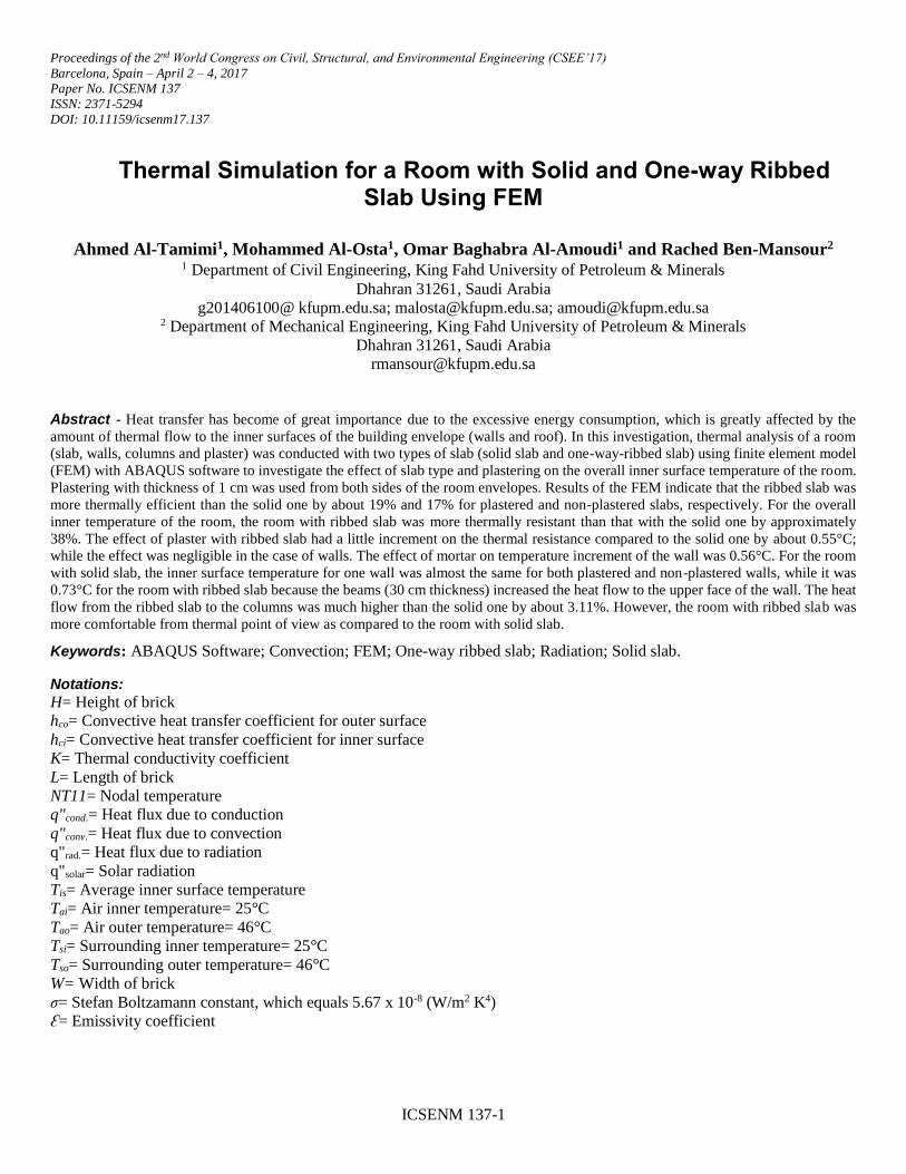
The walls were made of masonry hollow concrete bricks (40x20x20 cm) with four holes with the arrangement shown in
Fig. 1a. Further, the connection mortar between the masonry concrete bricks was used with 1 cm thickness, as shown in Fig.
1b.
Fig. 1: (a) Masonry hollow concrete bricks; (b) Connection mortar between the masonry hollow concrete bricks.
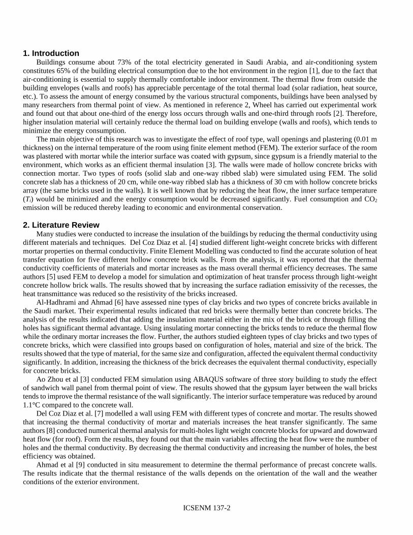
In the simulation, two types of roofs were considered. The solid slab with 20 cm thickness (Fig. 2a) was exposed to solar
radiation and external temperature. Similarly, one-way ribbed slab (known locally as Hordi) with 30 cm thickness (Fig. 2b)
was analysed to show the difference between the two roofs.
Fig. 2: (a) Solid slab with 0.20m thickness; (b) One-way ribbed slab.
The room was plastered from both sides with cement mortar and gypsum. Walls and slabs were covered with mortar on
the outer surface and gypsum on the inner surface. The thickness of the plaster layers was 1cm.
3.2 Heat Transfer Analysis
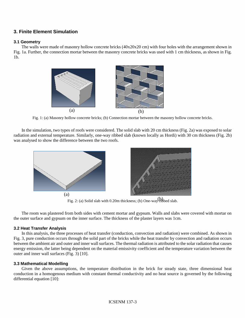
In this analysis, the three processes of heat transfer (conduction, convection and radiation) were combined. As shown in
Fig. 3, pure conduction occurs through the solid part of the bricks while the heat transfer by convection and radiation occurs
between the ambient air and outer and inner wall surfaces. The thermal radiation is attributed to the solar radiation that causes
energy emission, the latter being dependent on the material emissivity coefficient and the temperature variation between the
outer and inner wall surfaces (Fig. 3) [10].
3.3 Mathematical Modelling
Given the above assumptions, the temperature distribution in the brick for steady state, three dimensional heat
conduction in a homogenous medium with constant thermal conductivity and no heat source is governed by the following
differential equation [10]:
(b)
(a) (b)
(a)
ICSENM 137-4
Ə2𝑇
Ə𝑥2+
Ə2𝑇
Ə𝑦2+
Ə2𝑇
Ə𝑧2= 0 (1)
Fig. 3: Boundary conditions for inner and outer surfaces of the brick.
3.4 Boundary Conditions
In order to solve the above equation, the boundary conditions (B.C) at all surfaces have to be defined. For the outer
surface of the brick, which is exposed to solar load (during the day) and natural convection, the B.C can be written as:
𝐴𝑡 𝑧 = 0, −𝑘Ə𝑇
Ə𝑧= 𝑞"𝑠𝑜𝑙𝑎𝑟 + 𝑞"𝑐𝑜𝑛𝑣. + 𝑞"𝑟𝑎𝑑. (2)
−𝑘Ə𝑇
Ə𝑧= 𝑞"𝑠𝑜𝑙𝑎𝑟 + ℎ𝑐𝑜(T𝑎𝑜 – T(x, y, z = 0)) + Ɛσ(𝑇4
𝑠𝑜 – T4(x, y, z = 0)) (3)
Similarly, for the inner surface of the brick we write:
𝐴𝑡 𝑧 = 𝑊, −𝑘Ə𝑇
Ə𝑧= 𝑞"𝑐𝑜𝑛𝑣. + 𝑞"𝑟𝑎𝑑 (4)
−𝑘Ə𝑇
Ə𝑧= ℎ𝑐𝑖(𝑇(𝑥, 𝑦, 𝑧 = 𝑊) − 𝑇𝑎𝑖 ) + Ɛ𝜎( 𝑇4(𝑥, 𝑦, 𝑧 = 0) − 𝑇4
𝑠𝑖) (5)
For the top, bottom and side surfaces of the brick, we assume symmetrical B.Cs and, hence, no heat loss. Therefore, we
write:
𝐴𝑡 𝑥 = 0, 𝑥 = 𝐿
−𝑘Ə𝑇
Ə𝑥= 0, 𝑎𝑡 𝑥 = 0, 𝐿 (6)
𝐴𝑡 𝑦 = 0, 𝑦 = 𝐻
−𝑘Ə𝑇
Ə𝑦= 0, 𝑎𝑡 𝑦 = 0, 𝐻 (7)
z x
y
Height (H)
Inner surface
Outer surface
q"solar
q"conv
q"rad q"cond
Outer surface
q"conv
q"rad
q"cond
Inner surface
ICSENM 137-5
For the all inner surfaces of the brick holes, we also assume no heat transfer, hence
−𝑘Ə𝑇
Ə𝑛= 0, 𝑛: 𝑛𝑜𝑟𝑚𝑎𝑙 𝑐𝑜𝑜𝑟𝑑𝑖𝑛𝑎𝑡𝑒 𝑡𝑜 𝑎𝑛𝑦 𝑠𝑢𝑟𝑓𝑎𝑐𝑒 (8)
It is true that the heat transfer can occur by natural convection and radiation. However, in this study conduction is
assumed to be the main mode of heat transfer. The effect of natural convection and radiation will be studied later. As shown
previously in Equations (3) and (5), the following parameters are essential to solve the Equations to find T at z=W, which is
the inner surface temperature of the brick and indicated in this study by the symbol (Tis). The parameters were taken for the
eastern of Saudi environment.
3.5 Thermal Properties of Masonry Bricks and Plaster
As shown in Table 1, four materials were used in the simulation in ABAQUS software. The thermal properties of the
materials used are presented in Table 1 [11, 12, 14].
Table 1: Thermal properties of used materials.
PROPERTY Units Concrete Bricks Concrete Mortar Gypsum
Thermal conductivity (K) W/m°C 0.72 1.05 0.72 0.50
Film Coefficient (h) W/m2°C 8.70 8.90 8.90 9
Emissivity Coefficient (ℰ) --- 0.93 0.85 0.85 0.85
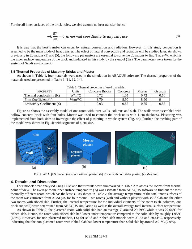
Figure 4a shows the assembly model of one room with three walls, columns and slab. The walls were assembled with
hollow concrete brick with four holes. Mortar was used to connect the brick units with 1 cm thickness. Plastering was
implemented from both sides to investigate the effect of plastering in whole system (Fig. 4b). Further, the meshing part of
the model was shown in Fig. 4c with segments of 4 cm size.
Fig. 4: ABAQUS model: (a) Room without plaster; (b) Room with both sides plaster; (c) Meshing.
4. Results and Discussion Four models were analysed using FEM and their results were summarized in Table 2 to assess the rooms from thermal
point of view. The average room inner surface temperature (Ti) was estimated from ABAQUS software to find out the most
thermally efficient room, which has the least Ti. As shown in Table 2, the average temperature of the total inner surfaces of
the room was estimated from ABAQUS for four rooms. Two rooms (with and without plaster) with solid slab and the other
two rooms with ribbed slab. Further, the internal temperature for the individual elements of the room (slab, columns, one
brick and wall) were determined from ABAQUS simulation as well as the overall average total internal surface temperature.
As shown in Table 2, the plastered room with solid slab had an average Ti around 29.59°C while it was 27.64°C for
ribbed slab. Hence, the room with ribbed slab had lower inner temperature compared to the solid slab by roughly 1.95°C
(6.6%). However, for non-plastered models, (Ti) for solid and ribbed slab models were 31.32 and 30.41°C, respectively,
indicating that the non-plastered room with ribbed slab had lower temperature than solid slab by around 0.91°C (2.9%).
Slab
Wall
Column
Wall
(a) (b)
Mortar
plaster
Gypsum
plaster
(c)
ICSENM 137-6
Table 2: The average temperature (°C) of the total inner surface of the room.
Element Solid Slab Ribbed Slab
WP WOP WP WOP
One brick
----- 27.83 ----- 27.83
One wall
28.29 28.39 28.38 28.50
Slab
37.92 40.30 30.71 33.64
Columns
----- 41.76 ----- 43.10
Ave. total internal Temp.
29.59 31.32 27.64 30.41
WP: With both sides plaster; WOP: Without plaster
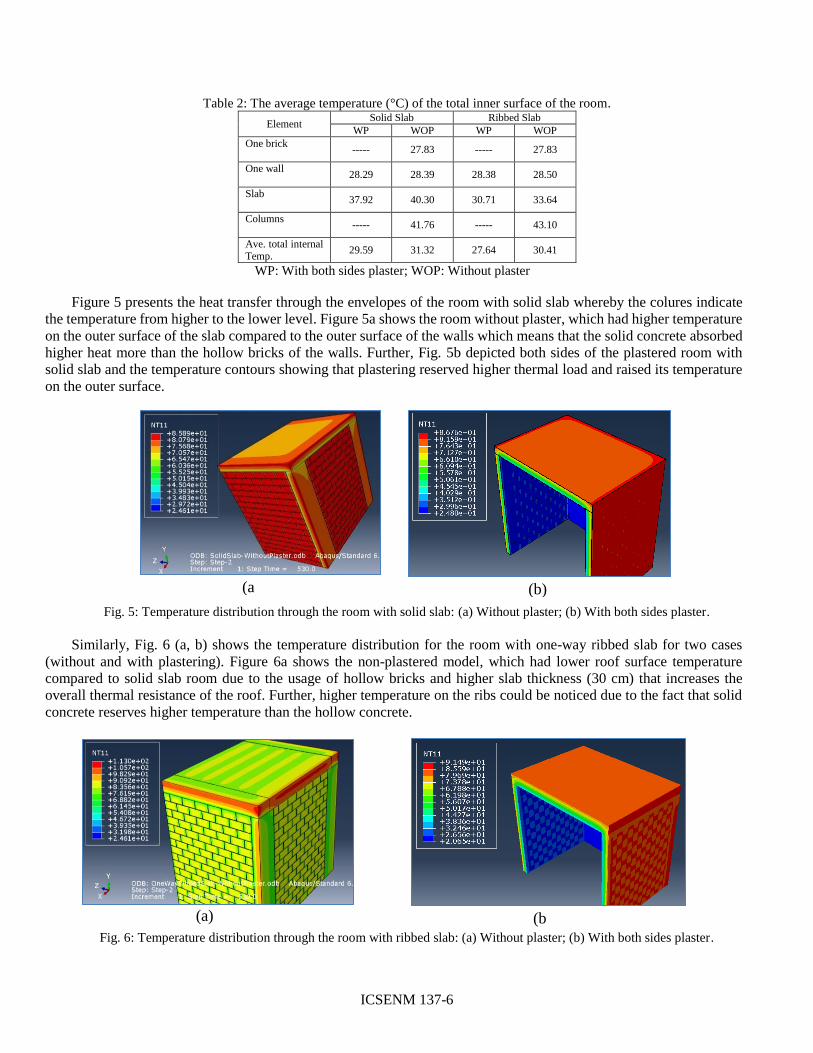
Figure 5 presents the heat transfer through the envelopes of the room with solid slab whereby the colures indicate
the temperature from higher to the lower level. Figure 5a shows the room without plaster, which had higher temperature
on the outer surface of the slab compared to the outer surface of the walls which means that the solid concrete absorbed
higher heat more than the hollow bricks of the walls. Further, Fig. 5b depicted both sides of the plastered room with
solid slab and the temperature contours showing that plastering reserved higher thermal load and raised its temperature
on the outer surface.
Fig. 5: Temperature distribution through the room with solid slab: (a) Without plaster; (b) With both sides plaster.
Similarly, Fig. 6 (a, b) shows the temperature distribution for the room with one-way ribbed slab for two cases
(without and with plastering). Figure 6a shows the non-plastered model, which had lower roof surface temperature
compared to solid slab room due to the usage of hollow bricks and higher slab thickness (30 cm) that increases the
overall thermal resistance of the roof. Further, higher temperature on the ribs could be noticed due to the fact that solid
concrete reserves higher temperature than the hollow concrete.
Fig. 6: Temperature distribution through the room with ribbed slab: (a) Without plaster; (b) With both sides plaster.
(a) (b
)
(a
) (b)
ICSENM 137-7
4.1. Role of wall
The outer surface temperature of the walls was the maximum while the inner surface temperature was the minimum, as
shown in Figs. 5 and 6. The average temperature of the interior surface of plastered and non-plastered walls were roughly
28.29 and 28.39°C, respectively for solid slab room (Table 2) with a difference between the two models of around 0.10°C.
Similarly, the temperature difference was 0.12°C for ribbed slab. Hence, the advantage of plastering walls was almost same
for solid and ribbed slab. Further, the wall in ribbed slab room had higher average temperature compared to the solid slab
with a difference around 0.09 and 0.11°C for plastered and non-plastered walls, respectively, due to the fact that ribbed slab
transfer higher heat to the upper face of the walls compared to the solid slab due to the higher thickness of ribbed slab.
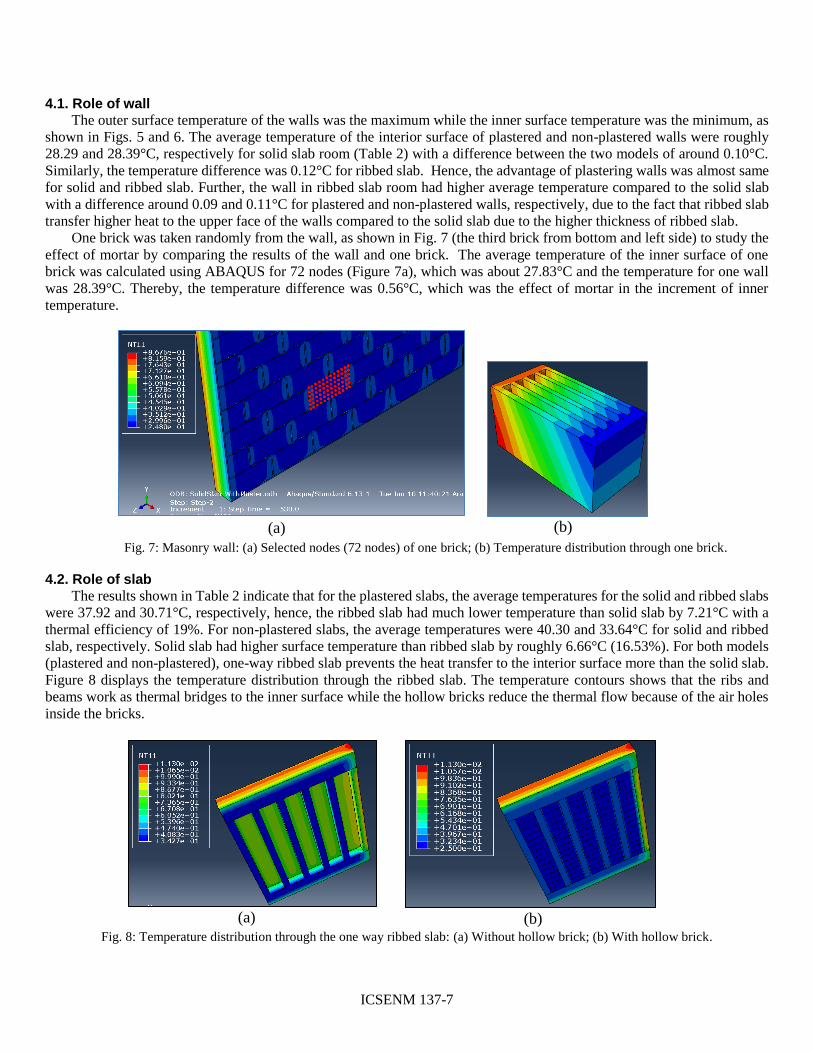
One brick was taken randomly from the wall, as shown in Fig. 7 (the third brick from bottom and left side) to study the
effect of mortar by comparing the results of the wall and one brick. The average temperature of the inner surface of one
brick was calculated using ABAQUS for 72 nodes (Figure 7a), which was about 27.83°C and the temperature for one wall
was 28.39°C. Thereby, the temperature difference was 0.56°C, which was the effect of mortar in the increment of inner
temperature.
Fig. 7: Masonry wall: (a) Selected nodes (72 nodes) of one brick; (b) Temperature distribution through one brick.
4.2. Role of slab
The results shown in Table 2 indicate that for the plastered slabs, the average temperatures for the solid and ribbed slabs
were 37.92 and 30.71°C, respectively, hence, the ribbed slab had much lower temperature than solid slab by 7.21°C with a
thermal efficiency of 19%. For non-plastered slabs, the average temperatures were 40.30 and 33.64°C for solid and ribbed
slab, respectively. Solid slab had higher surface temperature than ribbed slab by roughly 6.66°C (16.53%). For both models
(plastered and non-plastered), one-way ribbed slab prevents the heat transfer to the interior surface more than the solid slab.
Figure 8 displays the temperature distribution through the ribbed slab. The temperature contours shows that the ribs and
beams work as thermal bridges to the inner surface while the hollow bricks reduce the thermal flow because of the air holes
inside the bricks.
Fig. 8: Temperature distribution through the one way ribbed slab: (a) Without hollow brick; (b) With hollow brick.
(a) (b)
(a) (b)
ICSENM 137-8
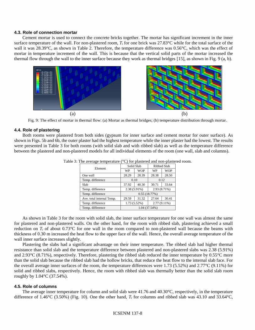
4.3. Role of connection mortar
Cement mortar is used to connect the concrete bricks together. The mortar has significant increment in the inner
surface temperature of the wall. For non-plastered room, Ti for one brick was 27.83°C while for the total surface of the
wall it was 28.39°C, as shown in Table 2. Therefore, the temperature difference was 0.56°C, which was the effect of
mortar in temperature increment of the wall. This is because that the vertical solid parts of the mortar increased the
thermal flow through the wall to the inner surface because they work as thermal bridges [15], as shown in Fig. 9 (a, b).
Fig. 9: The effect of mortar in thermal flow: (a) Mortar as thermal bridges; (b) temperature distribution through mortar.
4.4. Role of plastering
Both rooms were plastered from both sides (gypsum for inner surface and cement mortar for outer surface). As
shown in Figs. 5b and 6b, the outer plaster had the highest temperature while the inner plaster had the lowest. The results
were presented in Table 3 for both rooms (with solid slab and with ribbed slab) as well as the temperature difference
between the plastered and non-plastered models for all individual elements of the room (one wall, slab and columns).
Table 3: The average temperature (°C) for plastered and non-plastered room.
Element Solid Slab Ribbed Slab
WP WOP WP WOP
One wall 28.29 28.39 28.38 28.50
Temp. difference 0.10 0.12
Slab 37.92 40.30 30.71 33.64
Temp. difference 2.38 (5.91%) 2.93 (8.71%)
Temp. difference 0.55 (18.77%)
Ave. total internal Temp. 29.59 31.32 27.64 30.41
Temp. difference 1.73 (5.52%) 2.77 (9.11%)
Temp. difference 1.04 (37.54%)
As shown in Table 3 for the room with solid slab, the inner surface temperature for one wall was almost the same
for plastered and non-plastered walls. On the other hand, for the room with ribbed slab, plastering achieved a small
reduction on Ti of about 0.73°C for one wall in the room compared to non-plastered wall because the beams with
thickness of 0.30 m increased the heat flow to the upper face of the wall. Hence, the overall average temperature of the
wall inner surface increases slightly.
Plastering the slabs had a significant advantage on their inner temperature. The ribbed slab had higher thermal
resistance than solid slab and the temperature difference between plastered and non-plastered slabs was 2.38 (5.91%)
and 2.93°C (8.71%), respectively. Therefore, plastering the ribbed slab reduced the inner temperature by 0.55°C more
than the solid slab because the ribbed slab had the hollow bricks, that reduce the heat flow to the internal slab face. For
the overall average inner surfaces of the room, the temperature differences were 1.73 (5.52%) and 2.77°C (9.11%) for
solid and ribbed slabs, respectively. Hence, the room with ribbed slab was thermally better than the solid slab room
roughly by 1.04°C (37.54%).
4.5. Role of columns
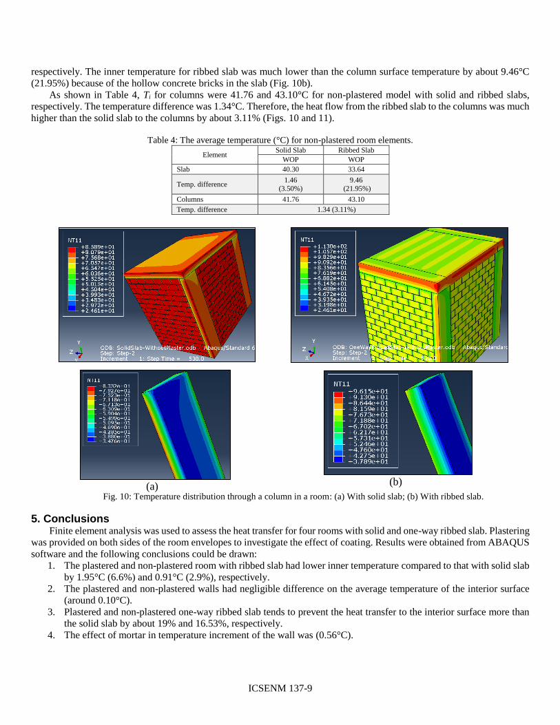
The average inner temperature for column and solid slab were 41.76 and 40.30°C, respectively, in the temperature
difference of 1.46°C (3.50%) (Fig. 10). One the other hand, Ti for columns and ribbed slab was 43.10 and 33.64°C,
(a) (b)
ICSENM 137-9
respectively. The inner temperature for ribbed slab was much lower than the column surface temperature by about 9.46°C
(21.95%) because of the hollow concrete bricks in the slab (Fig. 10b).
As shown in Table 4, Ti for columns were 41.76 and 43.10°C for non-plastered model with solid and ribbed slabs,
respectively. The temperature difference was 1.34°C. Therefore, the heat flow from the ribbed slab to the columns was much
higher than the solid slab to the columns by about 3.11% (Figs. 10 and 11).
Table 4: The average temperature (°C) for non-plastered room elements.
Element Solid Slab Ribbed Slab
WOP WOP
Slab 40.30 33.64
Temp. difference 1.46
(3.50%)
9.46
(21.95%)
Columns 41.76 43.10
Temp. difference 1.34 (3.11%)
Fig. 10: Temperature distribution through a column in a room: (a) With solid slab; (b) With ribbed slab.
5. Conclusions Finite element analysis was used to assess the heat transfer for four rooms with solid and one-way ribbed slab. Plastering
was provided on both sides of the room envelopes to investigate the effect of coating. Results were obtained from ABAQUS
software and the following conclusions could be drawn:
1. The plastered and non-plastered room with ribbed slab had lower inner temperature compared to that with solid slab
by 1.95°C (6.6%) and 0.91°C (2.9%), respectively.
2. The plastered and non-plastered walls had negligible difference on the average temperature of the interior surface
(around 0.10°C).
3. Plastered and non-plastered one-way ribbed slab tends to prevent the heat transfer to the interior surface more than
the solid slab by about 19% and 16.53%, respectively.
4. The effect of mortar in temperature increment of the wall was (0.56°C).
(b) (a)
ICSENM 137-10
5. For the room with solid slab, the inner surface temperature for one wall was almost the same for plastered and non-
plastered walls while it was 0.73°C for the room with ribbed slab. This effect could be ascribed to the beams with a
thickness of 0.30 m that increased the heat flow to the upper face of the wall.
6. The effect of plaster with ribbed slab had a little increment in the thermal resistance compared to solid slab by about
0.55°C due to the fact that ribbed slab had the hollow bricks that reduce the heat flow to the internal slab face.
7. The heat flow from the ribbed slab to the columns was much higher than the solid slab to the columns by about
3.11%.
8. The room with ribbed slab was thermally better than the solid slab room roughly by 1.04°C (37.54%).
6. Acknowledgement The authors acknowledge the support of King Fahd University of Petroleum & Minerals, Dhahran, Saudi Arabia,
to conduct the research work presented in the paper.
7. References [1] S. A. Al-Ghamdi, A. Al-Gargossh, and K. A. Al-Shaibani, “Energy conservation by retrofitting : An
overview of office buildings in Saudi Arabia,” International Conference on IT, Architecture and Mechanical
Engineering- Dubai- UAE, 2015.
[2] A. Almujahid and Z. Kaneesamkandi, “Construction of a test room for evaluating thermal performance of
building wall systems under real,” International Journal of Innovative Research in Science, vol. 2, no. 6, pp.
2000–2007.
[3] A. Zhou, K. W. Wong, and D. Lau, “Thermal insulating concrete wall panel design for sustainable built
environment,” The Scientific world journal, vol. 11, pp. 1–10, 2014.
[4] J. Diaz, P. Nieto, C. Biempica, and M. Gero, “Analysis and optimization of the heat-insulating light concrete
hollow brick walls design by the finite element method,” Applied Thermal Engineering, vol. 27, no. 8–9. pp.
1445–1456, 2007.
[5] J. Diaz, P. Garcia-Nieto, F. Alvarez-Rabanal, M. Alonso-Martinez, J. Dominguez-Hernandez, and J. Perez-
Bella, “The use of response surface methodology to improve the thermal transmittance of lightweight
concrete hollow bricks by FEM,” Construction and Building Materials, vol. 52, pp. 331–344, 2014.
[6] L. M. Al-Hadhrami and A. Ahmad, “Assessment of thermal performance of different types of masonry bricks
used in Saudi Arabia,” Applied Thermal Engineering, vol. 29, no. 5–6, pp. 1123–1130, 2009.
[7] J. Diaz, P. Nieto, J. Sierra, and C. Biempica, “Nonlinear thermal optimization of external light concrete
multi-holed brick walls by the finite element method,” International Journal of Heat and Mass Transfer,
vol. 51, no. 7-8, pp. 1530–1541, 2008.
[8] J. J. Del Coz Díaz, P. J. García Nieto, L. M. Díaz Pérez, and P. Riesgo Fernández, “Nonlinear thermal
analysis of multi-holed lightweight concrete blocks used in external and non-habitable floors by FEM,”
International Journal of Heat and Mass Transfer, vol. 54, no. 1–3, pp. 533–548, 2011.
[9] A. Ahmad, M. Maslehuddin, and L. M. Al-Hadhrami, “In situ measurement of thermal transmittance and
thermal resistance of hollow reinforced precast concrete walls,” Energy Building, vol. 84, pp. 132–141,
2014.
[10] D. R. Tobergte and S. Curtis, Fundamentals of Heat and Mass Transfer, 7th edition, vol. 53, no. 9. 2013.
[11] I. Al-Naimi, “The potential for energy conservation in residential buildings in Dammam region, Saudi
Arabia,” PhD dissertation in Architecture, University of Newcastle-upon-Tyne, 1989.
[12] “Apache-Tables User Guide,” Integrated Environmental Solutions Limited,IES Virtual Environment 6.4.
[13] M. Schweiz, “table of emissivity of various surfaces.”
[14] M. Karmele Urbikain and J. M. Sala, “Heat transfer through a double-glazed unit with an internal louvered
blind: Determination of the thermal transmittance using a biquadratic equation,” International Journal of
Heat and Mass Transfer, vol. 55, no. 4, pp. 1226–1235, 2012.
[15] J. J. Del Coz Diaz, P. J. Garca Nieto, a. M. Rodriguez, a. L. Martinez-Luengas, and C. B. Biempica, “Non-

ICSENM 137-11
linear thermal analysis of light concrete hollow brick walls by the finite element method and experimental
validation,” Applied Thermal Engineering, vol. 26, no. 8–9, pp. 777–786, 2006.