thermal protection materials and systems: past, present ... · thermal protection materials and...
TRANSCRIPT

Thermal Protection Materials and Systems: Past, Present, and Future
Sylvia M. Johnson Entry Systems and Technology Division
NASA Ames Research Center [email protected]
Presented at Missouri University of Science and Technology Rolla, MO
April 4, 2013
https://ntrs.nasa.gov/search.jsp?R=20130014035 2020-03-29T10:19:25+00:00Z
Acknowledgements
• NASA: Thomas Squire, Robin Beck, Don Ellerby, Matt Gasch, Mairead Stackpoole, Helen Hwang, Deepak Bose, Frank Milos, Joe Conley, Dan Leiser, David Stewart, Ethiraj Venkatapathy, Bernie Laub, John Lawson
• ERC: Jay Feldman
2
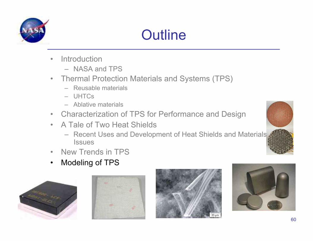
Outline • Introduction
– NASA and TPS • Thermal Protection Materials and Systems (TPS)
– Reusable materials – UHTCs – Ablative materials
• Characterization of TPS for Performance and Design • A Tale of Two Heat Shields
– Recent Uses and Development of Heat Shields and Materials Issues
• New Trends in TPS • Modeling of TPS
3
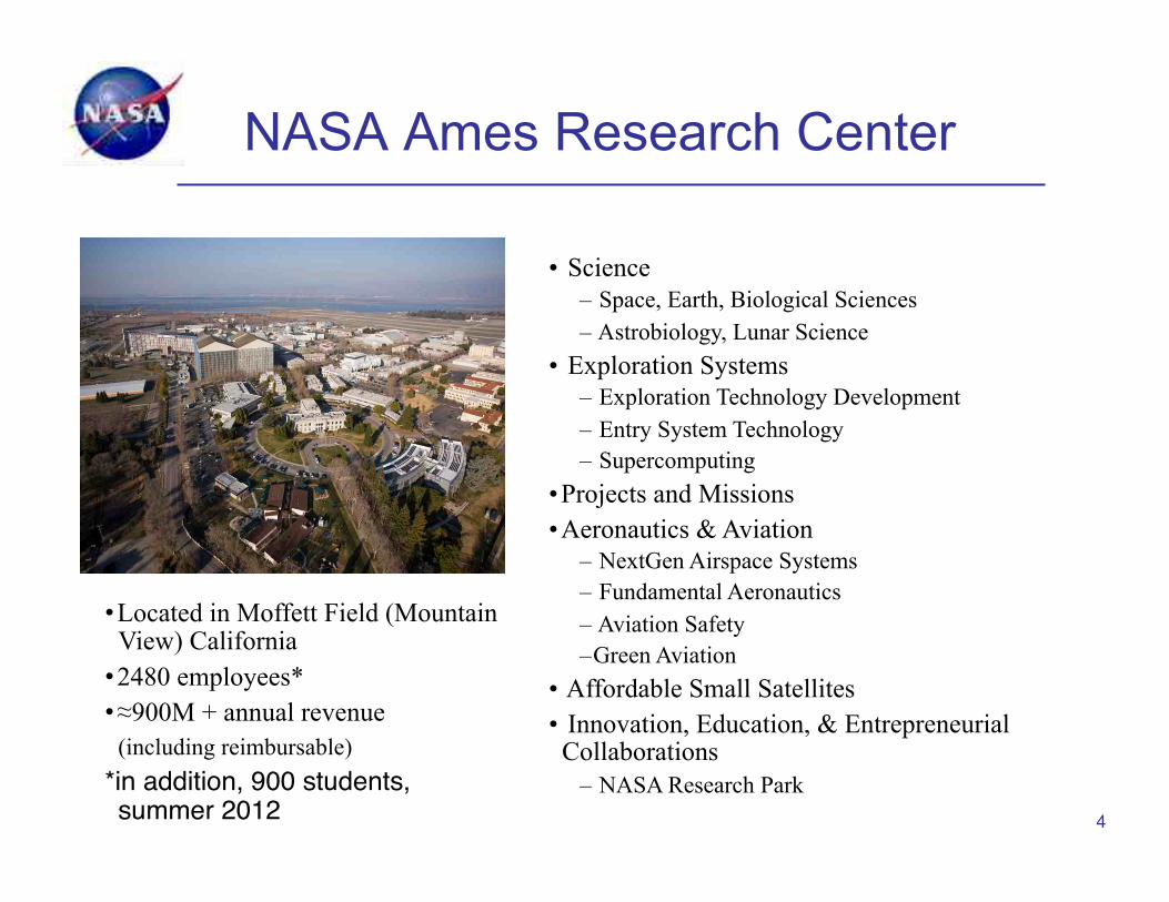
NASA Ames Research Center
4
• Located in Moffett Field (Mountain View) California
• 2480 employees* • !900M + annual revenue (including reimbursable) *in addition, 900 students, summer 2012"
• Science – Space, Earth, Biological Sciences – Astrobiology, Lunar Science
• Exploration Systems – Exploration Technology Development – Entry System Technology – Supercomputing
• Projects and Missions • Aeronautics & Aviation
– NextGen Airspace Systems – Fundamental Aeronautics – Aviation Safety – Green Aviation
• Affordable Small Satellites • Innovation, Education, & Entrepreneurial Collaborations
– NASA Research Park
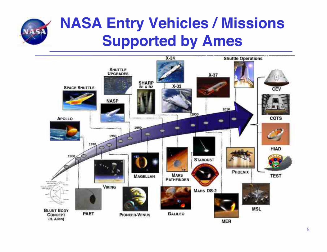
NASA Entry Vehicles / Missions Supported by Ames
5
Introduction to TPS
• NASA Ames focused on: – Qualifying and certifying TPS for current missions – Developing new TPS for upcoming missions
• Approaches to TPS development differ with risk —crewed vs. robotic missions: – Crewed
• Loss of life must be avoided • What must be done to qualify and certify TPS?
– Robotic missions • Can take more risk • But scientific knowledge can be lost too
• Goal for all TPS is efficient and reliable performance • Need to understand materials to enable design and use
6
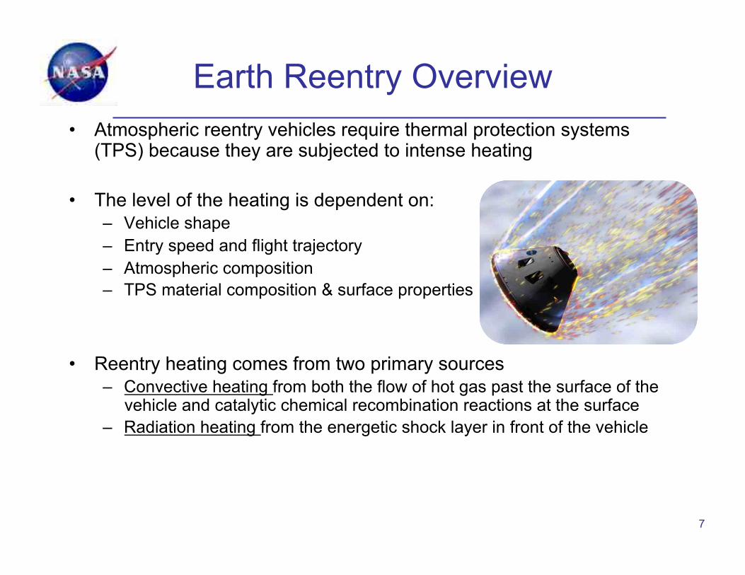
Earth Reentry Overview • Atmospheric reentry vehicles require thermal protection systems
(TPS) because they are subjected to intense heating
• The level of the heating is dependent on: – Vehicle shape – Entry speed and flight trajectory – Atmospheric composition – TPS material composition & surface properties
• Reentry heating comes from two primary sources – Convective heating from both the flow of hot gas past the surface of the
vehicle and catalytic chemical recombination reactions at the surface – Radiation heating from the energetic shock layer in front of the vehicle
7
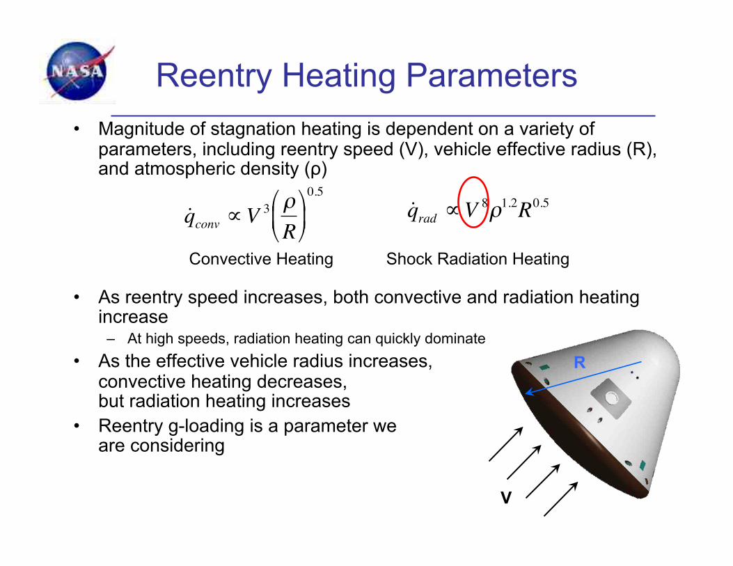
Reentry Heating Parameters • Magnitude of stagnation heating is dependent on a variety of
parameters, including reentry speed (V), vehicle effective radius (R), and atmospheric density (!)
• As reentry speed increases, both convective and radiation heating increase
– At high speeds, radiation heating can quickly dominate • As the effective vehicle radius increases,
convective heating decreases, but radiation heating increases
• Reentry g-loading is a parameter we are considering
2R
V
R
!
˙ q conv "V 3 #R$
% &
'
( )
0.5
!
˙ q rad "V 8#1.2R0.5
Convective Heating Shock Radiation Heating

Thermal Protection Systems
• Protect vehicle structure and contents (people and things) from the heat of entry through an atmosphere
• Rely on materials response to environment • Response depends on
– Material properties – Configuration of the system – Specific conditions (heat flux, pressure, flow)
One size does not fit all! Different TPS for different vehicles, location
on vehicles, and mission conditions
9

Reusable (Insulative) vs. Ablative TPS
10!

Energy management through storage and re-radiation — material unchanged
When exposed to atmospheric entry heating conditions, surface material will heat up and reject heat in the following ways:
• Re-radiation from the surface and internal storage during high heating condition
• Re-radiation and convective cooling under post-flight conditions
Insulative TPS
11!
radiation flux out
convective flux
radiation flux in
boundary layer or shock layer
high emissivity coating
low conductivity insulation TPS
backup or structure material
free stream
conduction flux
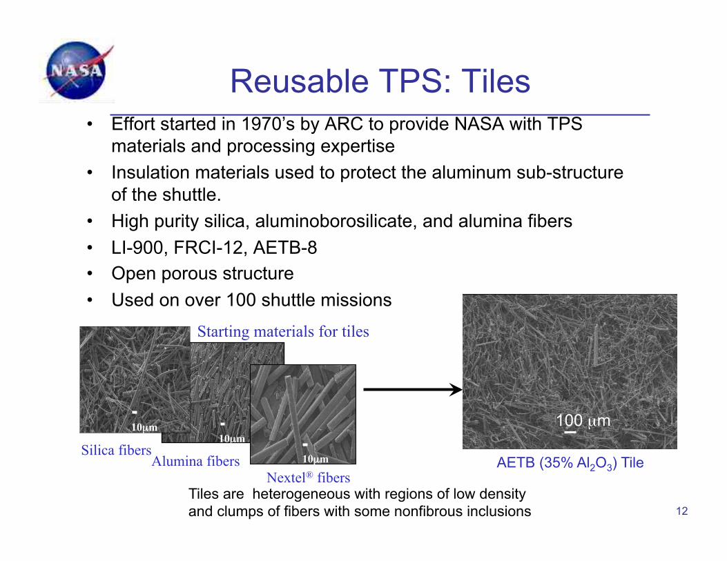
Reusable TPS: Tiles • Effort started in 1970’s by ARC to provide NASA with TPS
materials and processing expertise • Insulation materials used to protect the aluminum sub-structure
of the shuttle. • High purity silica, aluminoborosilicate, and alumina fibers • LI-900, FRCI-12, AETB-8 • Open porous structure • Used on over 100 shuttle missions
12
100 µm
AETB (35% Al2O3) Tile
10µm 10µm
10µm Silica fibers Alumina fibers
Nextel® fibers
Starting materials for tiles
Tiles are heterogeneous with regions of low density and clumps of fibers with some nonfibrous inclusions
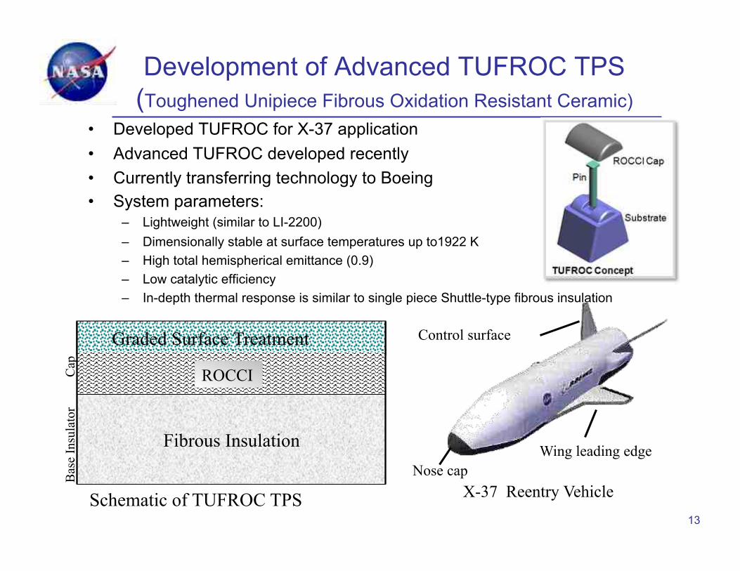
Cap
B
ase
Insu
lato
r
ROCCI
Fibrous Insulation
Graded Surface Treatment
Schematic of TUFROC TPS
Development of Advanced TUFROC TPS (Toughened Unipiece Fibrous Oxidation Resistant Ceramic)
• Developed TUFROC for X-37 application • Advanced TUFROC developed recently • Currently transferring technology to Boeing • System parameters:
– Lightweight (similar to LI-2200) – Dimensionally stable at surface temperatures up to1922 K – High total hemispherical emittance (0.9) – Low catalytic efficiency – In-depth thermal response is similar to single piece Shuttle-type fibrous insulation
13
X-37 Reentry Vehicle
Wing leading edge Nose cap
Control surface
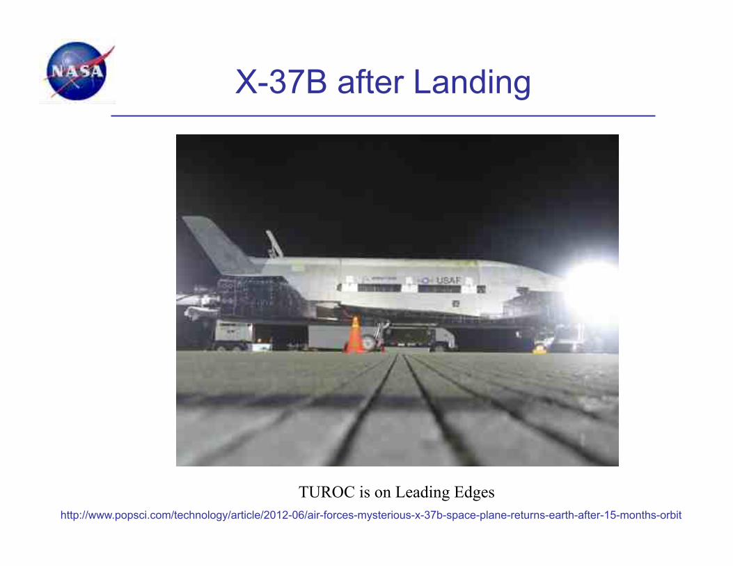
X-37B after Landing
http://www.popsci.com/technology/article/2012-06/air-forces-mysterious-x-37b-space-plane-returns-earth-after-15-months-orbit
TUROC is on Leading Edges
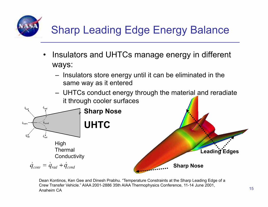
Sharp Leading Edge Energy Balance
• Insulators and UHTCs manage energy in different ways: – Insulators store energy until it can be eliminated in the
same way as it entered – UHTCs conduct energy through the material and reradiate
it through cooler surfaces
15
Dean Kontinos, Ken Gee and Dinesh Prabhu. “Temperature Constraints at the Sharp Leading Edge of a Crew Transfer Vehicle.” AIAA 2001-2886 35th AIAA Thermophysics Conference, 11-14 June 2001, Anaheim CA
UHTC
High Thermal Conductivity
Sharp Nose
Sharp Nose
Leading Edges
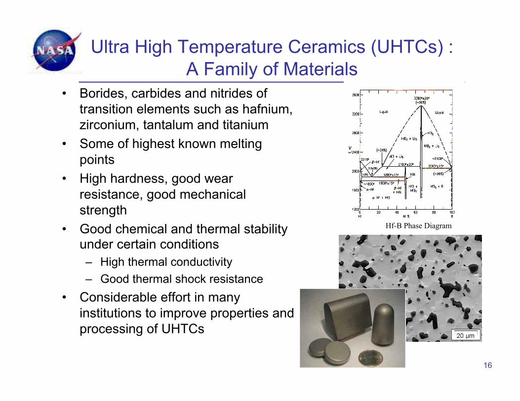
Ultra High Temperature Ceramics (UHTCs) : A Family of Materials
• Borides, carbides and nitrides of transition elements such as hafnium, zirconium, tantalum and titanium
• Some of highest known melting points
• High hardness, good wear resistance, good mechanical strength
• Good chemical and thermal stability under certain conditions – High thermal conductivity – Good thermal shock resistance
• Considerable effort in many institutions to improve properties and processing of UHTCs
16
Hf-B Phase Diagram
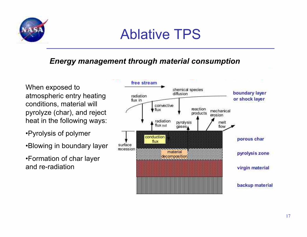
Energy management through material consumption
When exposed to atmospheric entry heating conditions, material will pyrolyze (char), and reject heat in the following ways:
• Pyrolysis of polymer
• Blowing in boundary layer
• Formation of char layer and re-radiation
Ablative TPS
17!

PICA Processing
18
Drying Cycle
Carbon Fiberform™
Resin Impregnation
Fiberform™ before impregnation
PICA: Fiberform™ with phenolic resin
Phenolic Resin!
PICA Arc Jet Model

PICA Background • Phenolic Impregnated Carbon
Ablator (PICA) was an enabling TPS material for the Stardust mission where it was used as a single piece heatshield
• PICA has the advantages of low density (~0.27g/cm3) coupled with efficient ablative capability at high heat fluxes
• PICA is the primary heatshield for Mars Science Lab (MSL) and SpaceX’s Dragon vehicle in a tiled configuration
19
Image of the sample return capsule post flight with PICA as the forebody TPS. (0.8m diameter)
MSL Heat Shield (4.5m diameter)
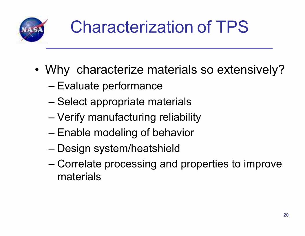
Characterization of TPS
• Why characterize materials so extensively? – Evaluate performance – Select appropriate materials – Verify manufacturing reliability – Enable modeling of behavior – Design system/heatshield – Correlate processing and properties to improve
materials
20
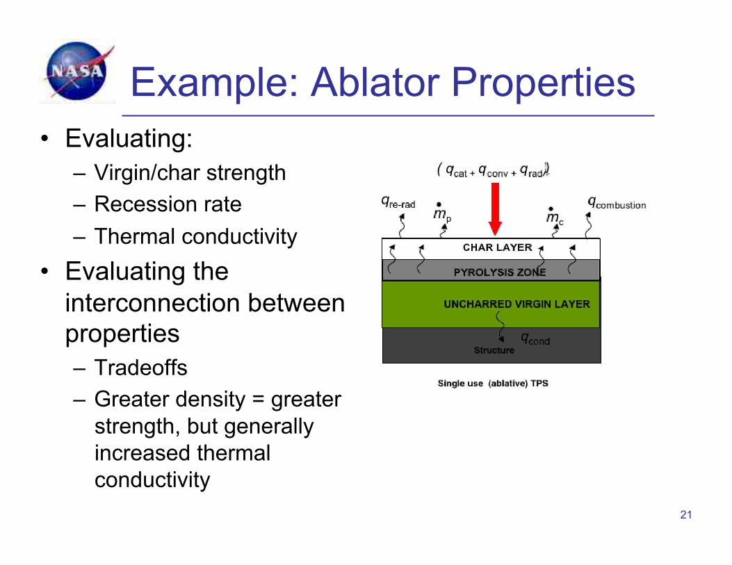
Example: Ablator Properties
21
• Evaluating: – Virgin/char strength – Recession rate – Thermal conductivity
• Evaluating the interconnection between properties – Tradeoffs – Greater density = greater
strength, but generally increased thermal conductivity

Material Properties
• Thermal properties – Thermal conductivity, specific heat, thermal
expansion • Physical properties
– Density, hardness, emissivity
• Mechanical properties – Strength, elastic modulus, toughness
• Properties may vary with temperature and/or pressure (porous materials)
• Microstructure depends on processing and composition
22
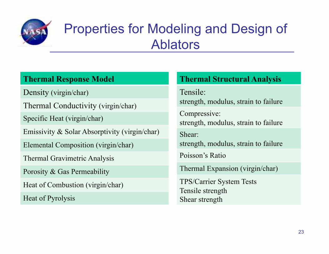
Properties for Modeling and Design of Ablators
23
Thermal Response Model Density (virgin/char)
Thermal Conductivity (virgin/char)
Specific Heat (virgin/char)
Emissivity & Solar Absorptivity (virgin/char)
Elemental Composition (virgin/char)
Thermal Gravimetric Analysis
Porosity & Gas Permeability
Heat of Combustion (virgin/char)
Heat of Pyrolysis
Thermal Structural Analysis Tensile: strength, modulus, strain to failure Compressive: strength, modulus, strain to failure Shear: strength, modulus, strain to failure Poisson’s Ratio
Thermal Expansion (virgin/char)
TPS/Carrier System Tests Tensile strength Shear strength

Need for Arc Jet Testing
• Arc jet testing is the best ground-based method of evaluating a material’s oxidation/ablation response in re-entry environments
• Oxidation/ablation behavior on heating in static or flowing air at ambient pressures is likely to be significantly different than in a re-entry environment. – O2 and N2 may be dissociated
• Catalycity of the material • Recombination of O and N atoms
adds to surface heating – Stagnation pressures may be <1 atm.
• active to passive transitions in oxidation
– SiC : protective SiO2 layer is removed as SiO
24

Arc Jet Schematic
25
Vacuum Test Chamber !
High Energy Flow !Mach 5 - 7 at exit
10-45 MJ/kg Simulates altitudes 30 – 60 km
Gas Temp. > 12000 F
Simulates reentry conditions in a ground-based facility
Method: Heat a test gas (air) to plasma temperatures by an electric arc, then accelerate into a vacuum chamber and onto a stationary test article
Stine, H.A.; Sheppard, C.E.; Watson, V.R. Electric Arc Apparatus. U.S. Patent 3,360,988, January 2, 1968.
Selection of Appropriate Material
• Historical approach: – Use heritage materials: “It’s worked before…” – Risk-reduction strategy – Limited number of flight-qualified ablative materials – Different vehicle configurations and reentry conditions
(need to qualify materials in relevant environments)
• As missions become more demanding, we need higher capability materials — necessary to have a robust research and development program
• Reusable and ablative materials are both needed • Must test materials in relevant environments • Provide path for insertion/use of new materials
26

Technology Readiness Levels
27 https://www.spacecomm.nasa.gov/spacecomm/images//technology_TRLS.gif
A Tale of Two Heatshields
• 2 Vehicles – CEV/Orion/MPCV – Mars Science Lab (MSL)
• 2 destinations – Earth from the moon – Mars from Earth
• 2 materials – PICA – Avcoat
28

MPCV (Orion) TPS Requirements
• Multi-purpose Crew Vehicle (MPCV) Lunar Direct Return (LDR) conditions: – 11 km/s atmospheric entry – peak heat rate > 1000 W/cm2
• MPCV Low Earth Orbit (LEO) return conditions: – 8 km/s atmospheric entry – peak heat rate > 150 W/cm2
• Early TPS development work focused on PICA for this application
29
Heatshield
Back Shell
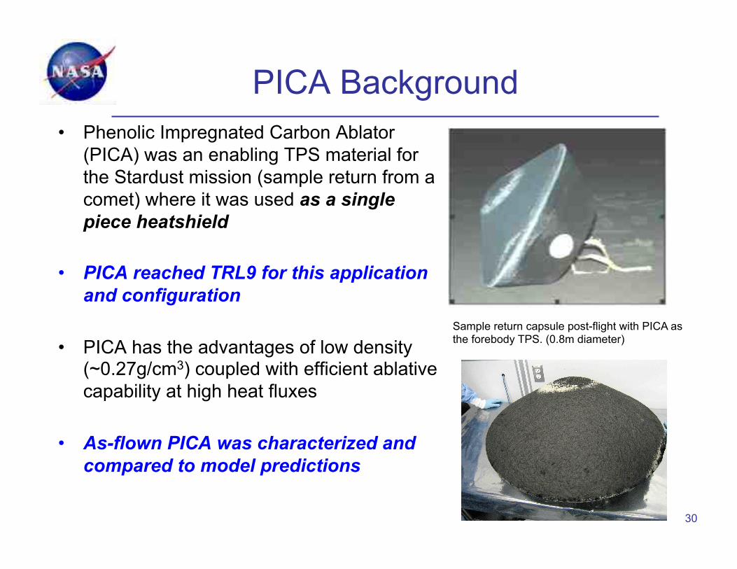
PICA Background • Phenolic Impregnated Carbon Ablator
(PICA) was an enabling TPS material for the Stardust mission (sample return from a comet) where it was used as a single piece heatshield
• PICA reached TRL9 for this application and configuration
• PICA has the advantages of low density (~0.27g/cm3) coupled with efficient ablative capability at high heat fluxes
• As-flown PICA was characterized and compared to model predictions
30
Sample return capsule post-flight with PICA as the forebody TPS. (0.8m diameter)

From PICA …….. • PICA had heritage…for Stardust
– Needed development effort for new applications • PICA was to be used in a tiled configuration
– Tiles require gap fillers or a way to deal with gaps
– PICA is a rigid material with a relatively low strength and strain to failure
– Risk analysis and design indicated that many small tiles would be required, increasing the number of gaps.
• PICA was extensively characterized and considerable effort was put into scale-up and manufacturing 31

…..to Avcoat • Avcoat was used on the
Apollo vehicles: “heritage” material
• Consists of a honeycomb filled with an ablative mixture
• Reduces gaps • Complex material
requiring hand assembly • Not made for many years 32
Before and after Avcoat arc jet models

Heatshield Comparison
33
PICA Acreage TPS Layout:
• 440 tiles • 133 Unique Tile Planforms • 832 Gap Fillers
RTV-SIP-RTV attachment to carrier structure
Avcoat Acreage TPS Layout
• 18 Gore Honeycomb Panels • 18 Shoulder Panels • 1 Center Panel
Bond honeycomb to carrier structure and ablator filled-in and cured.
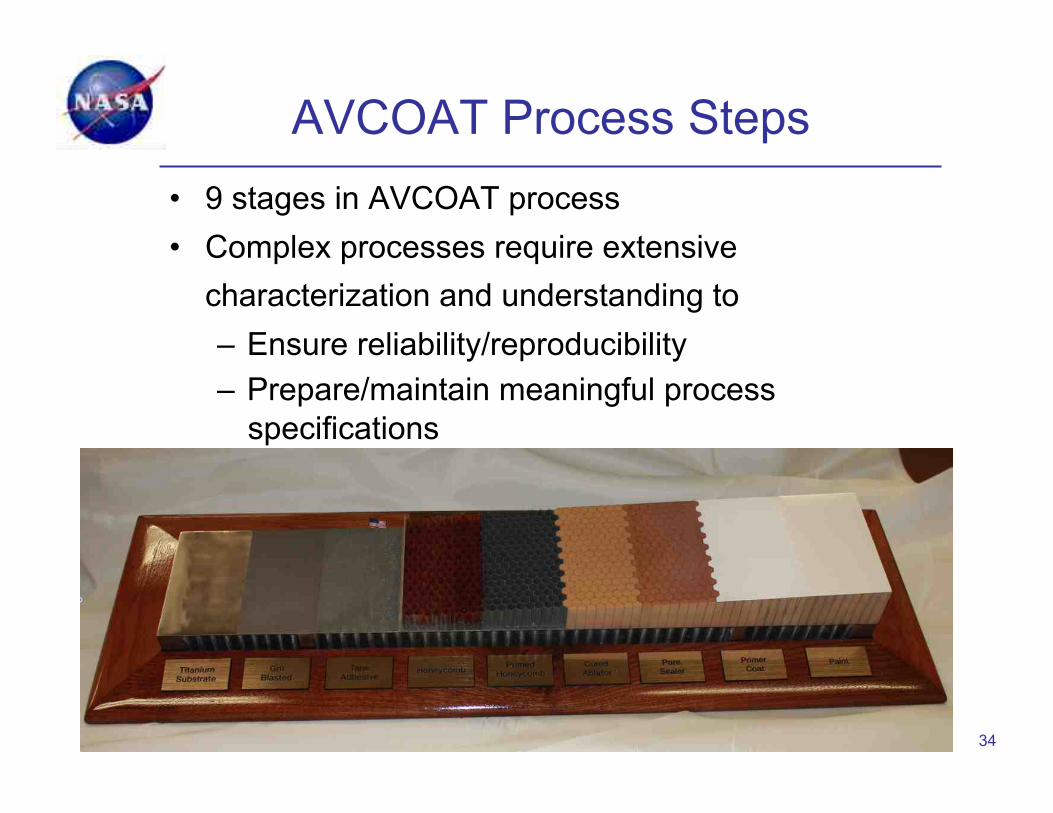
AVCOAT Process Steps • 9 stages in AVCOAT process • Complex processes require extensive
characterization and understanding to – Ensure reliability/reproducibility – Prepare/maintain meaningful process
specifications
34

Avcoat for MPCV Heatshield • Avcoat construction schematic showing the various steps and
processes involved in building the honeycombed ablator • Red arrows indicate areas were process changes were implemented
35

Issues with “Heritage” Materials
• Know-how may be lost over time • Materials/components may no longer be
available • Environmental/safety regulations may not
allow the use of certain processes • Recreation of materials can be time and
money-consuming – $25+million and 5 years has been spent on
recreating Avcoat
• Is it really “Avcoat”? 36
Meanwhile, Mars Science Lab in Development
• MSL was being fabricated simultaneously with CEV/Orion (MPCV)
• Initial choice for a heatshield TPS was SLA-561V, a heritage honeycomb-based material from Lockheed
• SLA-561V was used on all previous NASA Mars entry missions
• However, MSL was much larger ….. 37

Post test photo
SLA Subjected to Shear in Arc-Jet
38 During test
Note many cells completely emptied
Change of TPS Late in the Game
• Original choice of TPS did not pass shear tests
• Needed to use a more capable TPS • PICA was chosen • Previous/ongoing development of PICA for
CEV/Orion
39
Availability of data/processes critical in enabling the heat shield material to be qualified, certified and fabricated in time (18 months)
5/15/13!
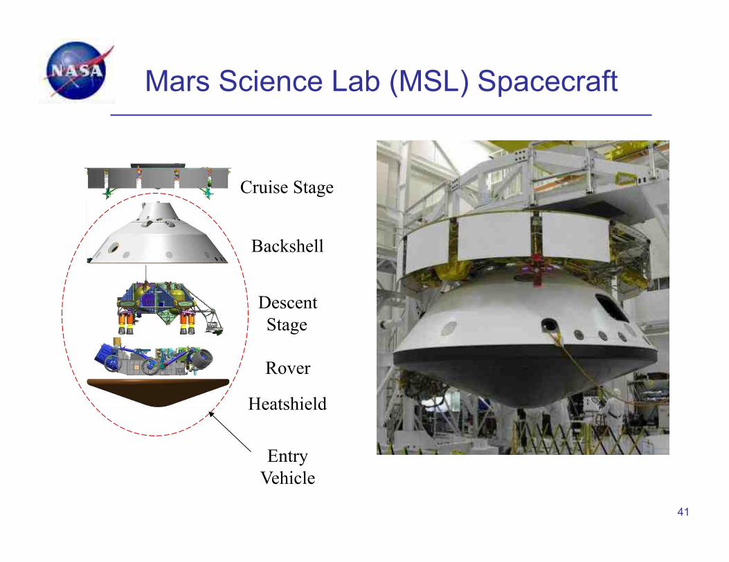
Mars Science Lab (MSL) Spacecraft
41
Cruise Stage
Backshell
Descent Stage
Rover
Heatshield
Entry Vehicle

Heatshield Fabrication in Process
RASB: 42

Heatshield Fabricated (gaps filled)
RASB: 43

Spacecraft Assembled
RASB: 44
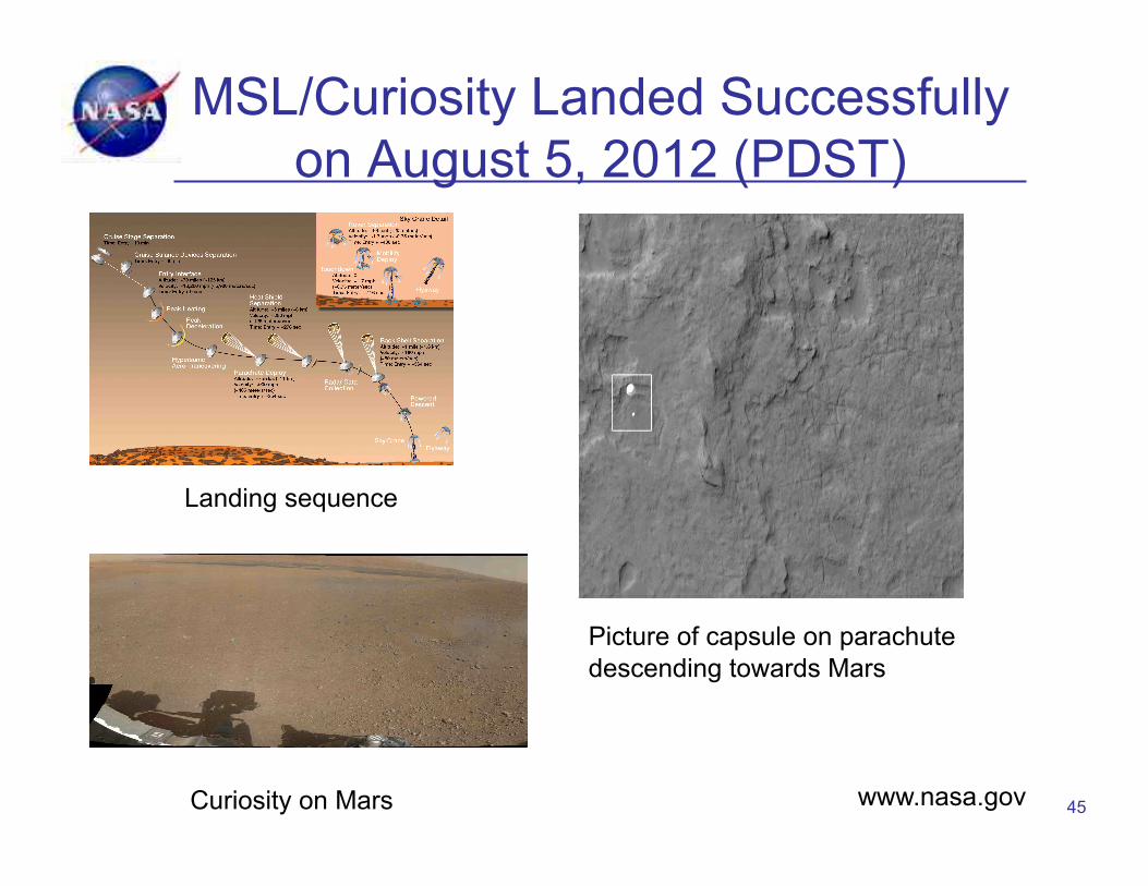
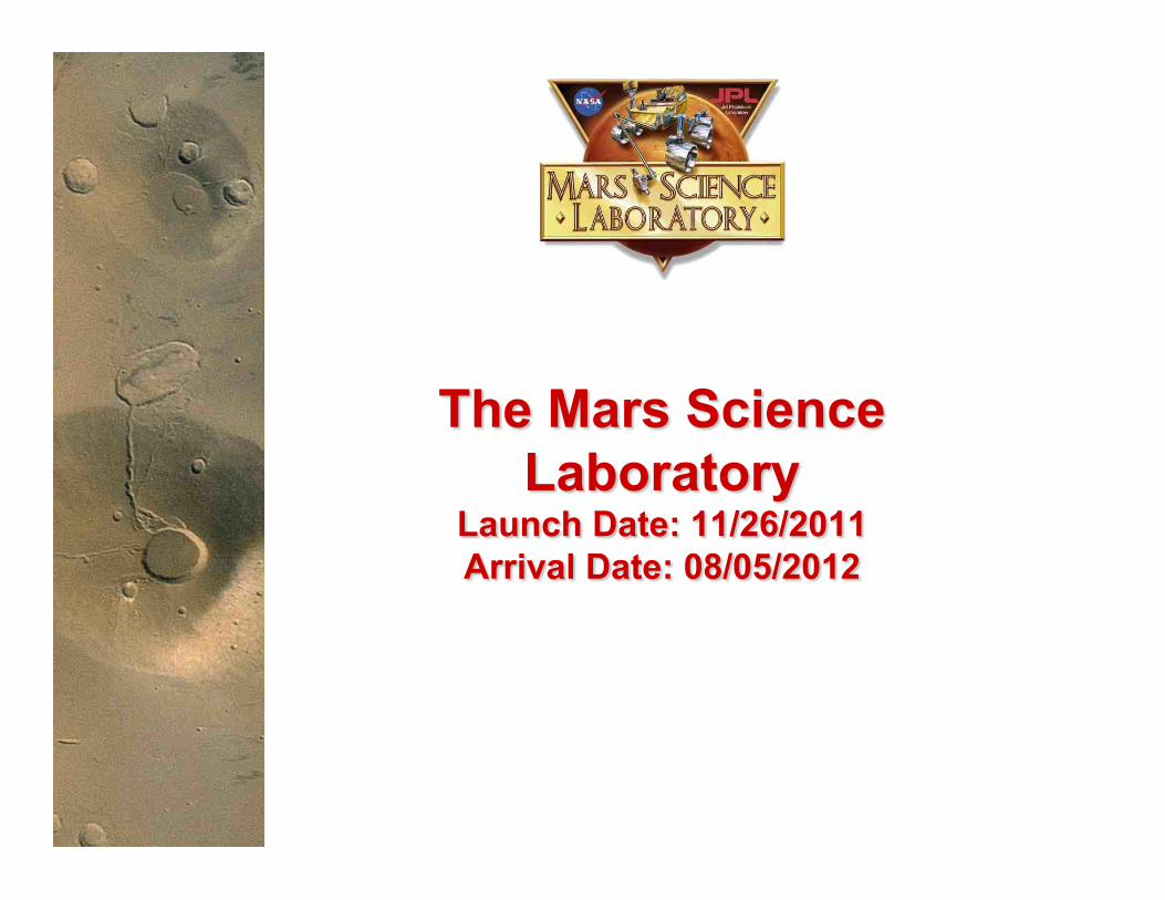
MSL/Curiosity Landed Successfully on August 5, 2012 (PDST)
• http://
45
Landing sequence
Picture of capsule on parachute descending towards Mars
www.nasa.gov Curiosity on Mars

MSL Heatshield on Mars
46
Heat shield about 50 feet (16 meters) from the spacecraft. Image credit: NASA/JPL-Caltech/MSSS
The four main pieces of hardware that arrived on Mars with NASA's Curiosity Image credit: NASA/JPL-Caltech/Univ. of Arizona
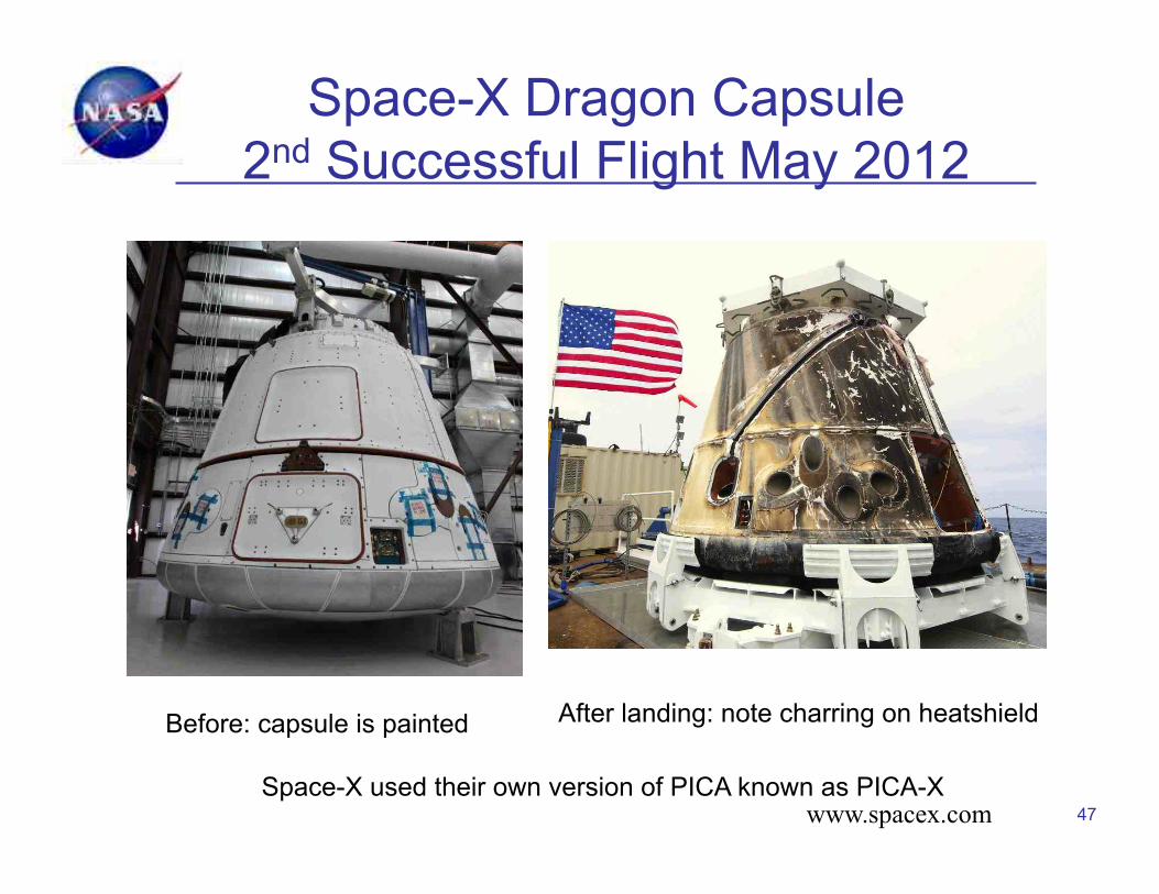
Space-X Dragon Capsule 2nd Successful Flight May 2012
47 www.spacex.com
Before: capsule is painted After landing: note charring on heatshield
Space-X used their own version of PICA known as PICA-X
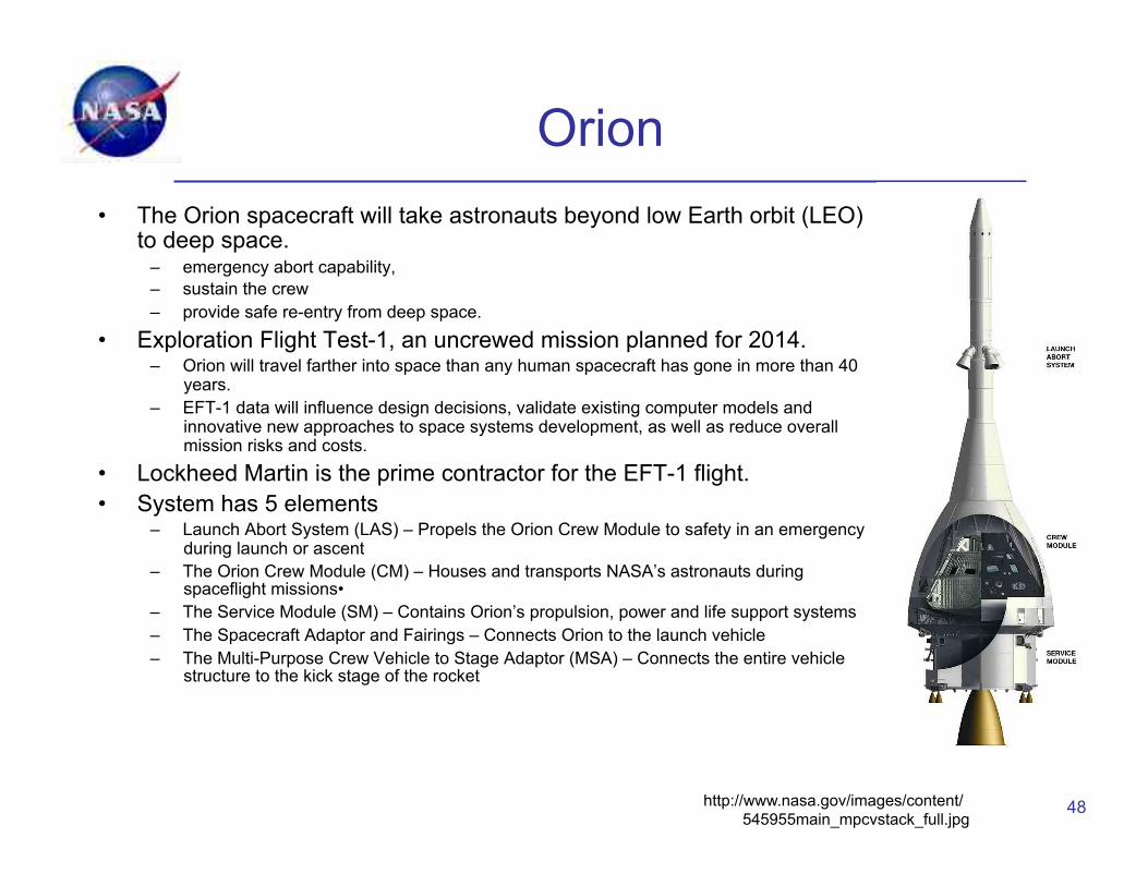
Orion • The Orion spacecraft will take astronauts beyond low Earth orbit (LEO)
to deep space. – emergency abort capability, – sustain the crew – provide safe re-entry from deep space.
• Exploration Flight Test-1, an uncrewed mission planned for 2014. – Orion will travel farther into space than any human spacecraft has gone in more than 40
years. – EFT-1 data will influence design decisions, validate existing computer models and
innovative new approaches to space systems development, as well as reduce overall mission risks and costs.
• Lockheed Martin is the prime contractor for the EFT-1 flight. • System has 5 elements
– Launch Abort System (LAS) – Propels the Orion Crew Module to safety in an emergency during launch or ascent
– The Orion Crew Module (CM) – Houses and transports NASA’s astronauts during spaceflight missions•
– The Service Module (SM) – Contains Orion’s propulsion, power and life support systems – The Spacecraft Adaptor and Fairings – Connects Orion to the launch vehicle – The Multi-Purpose Crew Vehicle to Stage Adaptor (MSA) – Connects the entire vehicle
structure to the kick stage of the rocket
48 http://www.nasa.gov/images/content/545955main_mpcvstack_full.jpg
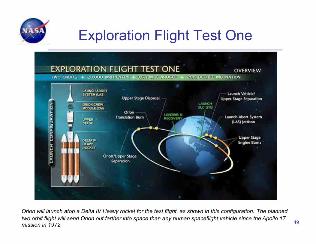
Exploration Flight Test One
49
Orion will launch atop a Delta IV Heavy rocket for the test flight, as shown in this configuration. The planned two orbit flight will send Orion out farther into space than any human spaceflight vehicle since the Apollo 17 mission in 1972.

Crew Module in Construction
50
• Crew module is being constructed by Lockheed Martin • Heatshield for EFT1is Avcoat
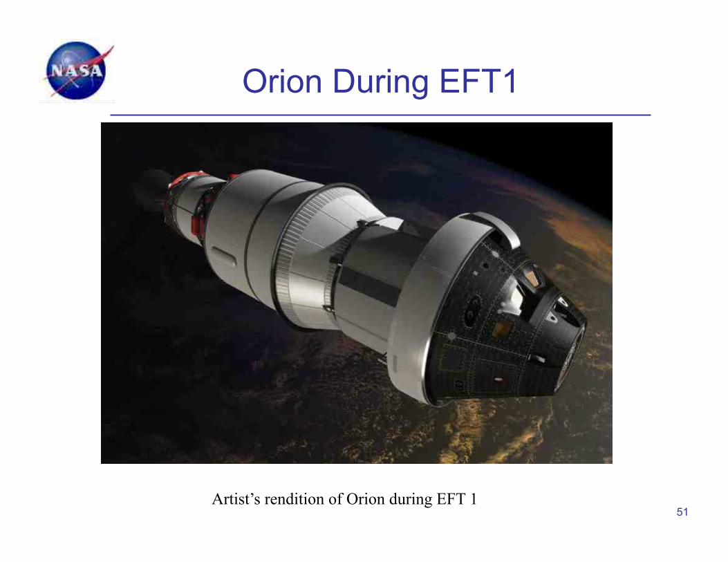
Orion During EFT1
51 Artist’s rendition of Orion during EFT 1

Outline • Introduction
– NASA and TPS • Thermal Protection Materials and Systems (TPS)
– Reusable materials – UHTCs – Ablative materials
• Characterization of TPS for Performance and Design • A Tale of Two Heat Shields
– Recent Uses and Development of Heat Shields and Materials Issues
• New Trends in TPS • Modeling of TPS
52

What are Rigid, Conformable and Flexible Ablative Materials?
• Rigid – fabricated in a rigid form and usually applied in a tiled configuration to a rigid substructure
• Conformable – fabricated in a flexible form and shaped to a rigid substructure; final form may be rigid or compliant
• Flexible – fabricated and used in a flexible form, where flexibility is an essential component of the heatshield, e.g., deployable systems, stowable systems
• Woven – can be any of the above 53

Conformable/Flexible Ablators • Fibrous substrate, such as felt or woven cloth • Matrix of various resins and fillers • Significant design, system integration, and
performance advantages over rigid ablators – Manufacturability – Reduction in piece-parts – Ease of assembly – Enables larger diameter aeroshells – Eliminates gap and seam issues
54 Conformable PICA Flexible PICA
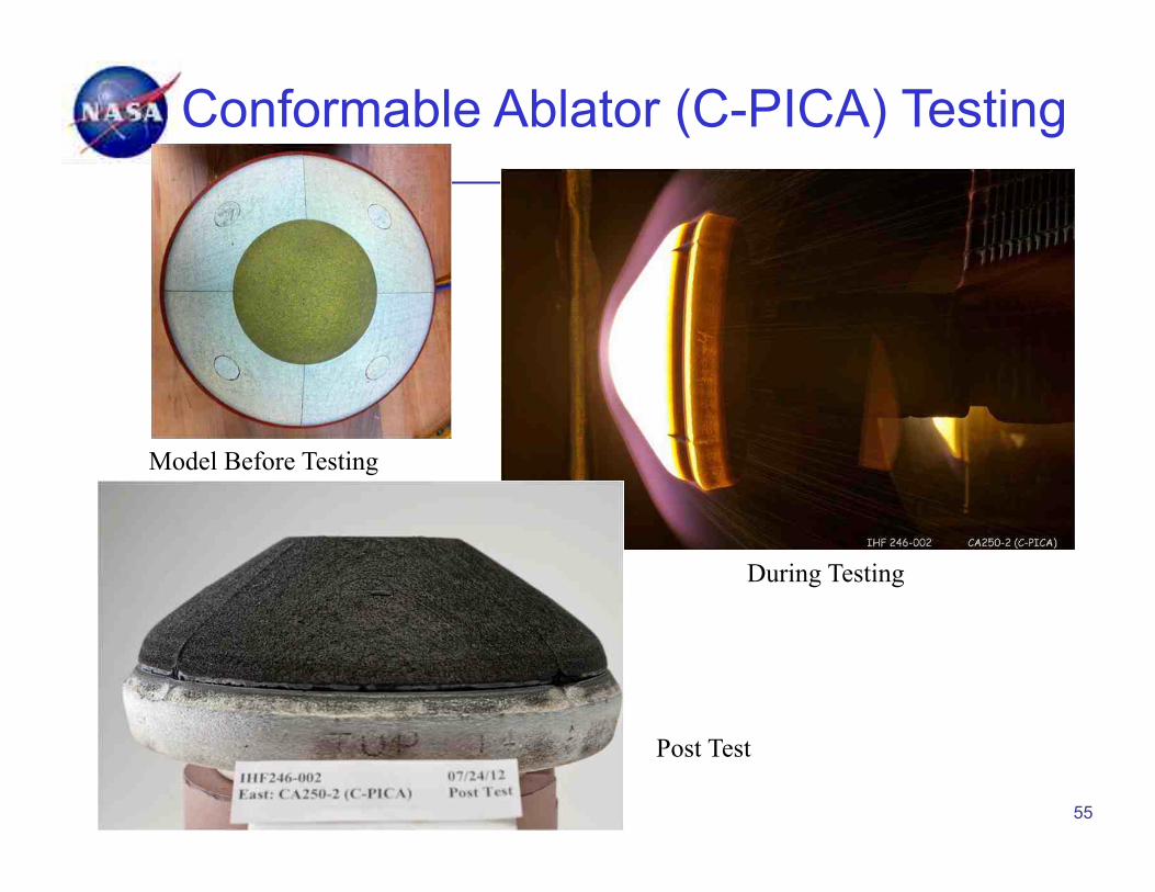
Conformable Ablator (C-PICA) Testing
C-SICA
Model Before Testing
During Testing
Post Test
55

Carbon Phenolic TPS • Carbon Phenolic TPS
– 1960s: fully dense (1.45-1.5 g/cm3) carbon phenolics were optimized
– only materials available for use at very high heat fluxes and high pressure conditions, yet the least favorable in terms of density
• Carbon phenolic material made from carbon fiber weaves fully infiltrated with phenolic resin
• Carbon phenolic TPS was used on Gallileo heat shield for very demanding entry into Jupiter’s atmosphere
• Current effort to investigate approaches to fabricating carbon phenolic materials – Issues with fiber supplies – Entry Grade CP needs Avtex Rayon – not
produced since 1986 56

TPS for Saturn and Uranus Probes
• The only flight proven TPS that can meet the extreme entry environment (heat-flux, pressure, etc) for Saturn and Uranus Probes, is heritage, entry grade carbon phenolic (HEGCP)
57
TPS G
AP
POC: [email protected]
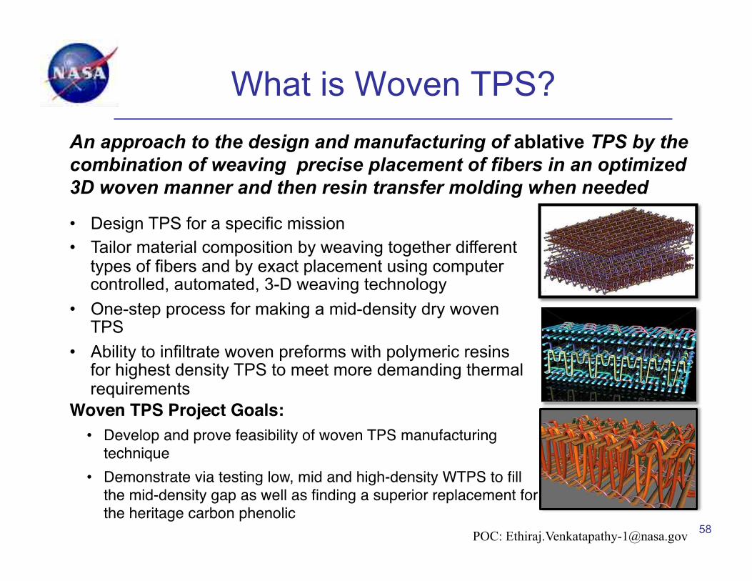
What is Woven TPS?
58
An approach to the design and manufacturing of ablative TPS by the combination of weaving precise placement of fibers in an optimized 3D woven manner and then resin transfer molding when needed
• Design TPS for a specific mission • Tailor material composition by weaving together different
types of fibers and by exact placement using computer controlled, automated, 3-D weaving technology
• One-step process for making a mid-density dry woven TPS
• Ability to infiltrate woven preforms with polymeric resins for highest density TPS to meet more demanding thermal requirements
Woven TPS Project Goals:!• Develop and prove feasibility of woven TPS manufacturing
technique "• Demonstrate via testing low, mid and high-density WTPS to fill
the mid-density gap as well as finding a superior replacement for the heritage carbon phenolic"
POC: [email protected]
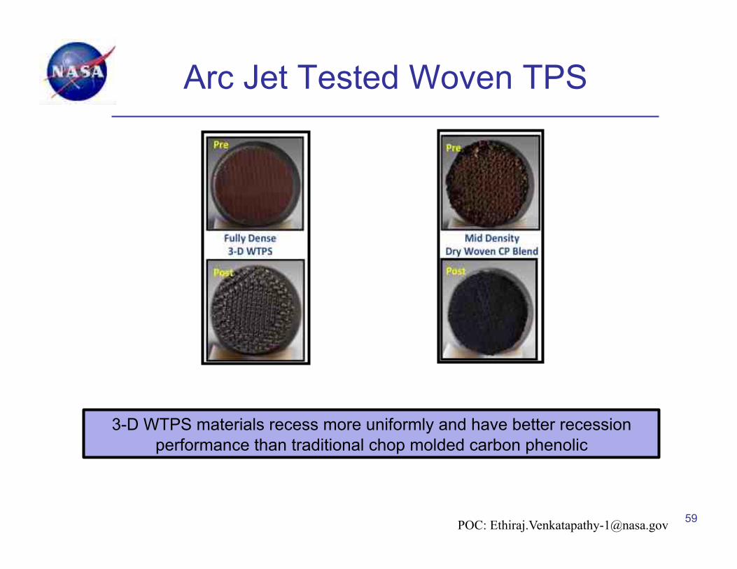
Arc Jet Tested Woven TPS
59
3-D WTPS materials recess more uniformly and have better recession performance than traditional chop molded carbon phenolic
POC: [email protected]
Outline • Introduction
– NASA and TPS • Thermal Protection Materials and Systems (TPS)
– Reusable materials – UHTCs – Ablative materials
• Characterization of TPS for Performance and Design • A Tale of Two Heat Shields
– Recent Uses and Development of Heat Shields and Materials Issues
• New Trends in TPS • Modeling of TPS
60
Instrumentation • All atmospheric entries are essentially
“experiments” from which we should gather data
• Data used to validate models and understand materials behavior better
• MSL was instrumented – MEDLI: Mars Entry Descent Landing
Instrumentation
61
Importance of MSL Instrumentation
• MEDLI is the most extensive ablative heat shield instrumentation suite since Apollo – 7 pressure sensors, 26 near surface and
in-depth thermocouples, 6 isotherm sensors
• Data being used to validate and improve Mars entry aerothermodynamic and TPS response models
• Better models mean TPS safety margin can be reduced and science payload increased
62

Computational Modeling of UHTCs Will Enhance Development
Goals • Reduce materials development time • Optimize material properties/tailor materials • Guide processing of materials • Develop design approaches Approach • Develop models integrated across various length
scales • Correlate models with experiment whenever
possible
63
Modeling UHTCs – What’s Next?
64
• Accomplishments – Ab initio calculations of lattice structure, bonding
characteristics, elastic constants, phonon spectra and thermal properties of ZrB2 and HfB2
– Ab initio calculations of formation and migration energies for simple defects (vacancies)
– Development of interatomic potentials for ZrB2 and HfB2 for atomistic simulations
• Opportunities – Ab initio calculations of simple/ideal grain boundary
structures with and without chemical impurities – No UHTC atomistic simulations exist in the literature. New
potentials mean the field is wide open! – FEM modeling of microstructure to relate processing and
properties

Fundamental Modeling of Ablators
• Pyrolysis chemistry (ab initio) – Pyrolysis simulation is very challenging: no
current solution • Phenolic networks (atomistic)
– Virtual mechanical and thermal testing – Phenolic network design parameters:
Linkage Sites and Cross-linking • Microstructure Modeling (continuum)
– X-ray CT images gives 3D micron scale, realistic microstructure
– FEM models for thermal/mechanical analysis
65
• Ablators for most demanding atmospheric entries • Intrinsically multi-scale materials and phenomena
PICA - carbon fiber/phenolic matrix
Summary • Two main classes plus specialized materials
– Insulating, e.g. space shuttle tiles – Ablators for higher heat fluxes – New materials for new missions – woven, conformable, etc.
• TPS needs to fit the application—location on vehicle, expected environment
• Heritage materials may not always be heritage – Substantial effort required to recreate
• Need to gain full data value from flights/experiments: instrumentation is key
• Critical to characterize materials and archive data – For selecting appropriate material – To ensure material demonstrates desired behavior – To have materials ready for new missions
• Modeling and analysis are critical to better understanding and prediction of material behavior in reentry
66 Goal of all TPS is reliable and efficient performance!

The End
67
Manufacturing Variability • Real-world manufacturing processes have
inherent variability. – These variations can lead to scatter in the
material properties. • Necessary to quantify allowable lot-to-lot
and in-lot variability of properties. – This may also include acceptable flaw and
inclusion size.
68

TPS for Outer Planet Missions: Carbon Phenolic Current Status
• Heritage Entry Grade Carbon Phenolic (HEGCP) – Most capable and robust TPS – Baseline TPS for the Saturn and Uranus Probe Missions – HEGCP is very capable, robust and enabled P-V & Galileo &
is flight proven
69
• Carbon Phenolic (CP) heat-shield is made of two types !– Chop Molded and Tape Wrapped CP"
• Tape wrap manufacturing needed for Rocket nozzles and DoDʼs ! slender entry body missiles – sustainable !• Chop Molded CP is needed only for NASA entry missions!• HEGCP needs Avtex Rayon – no longer produced (since 1986)!• NASA held two CP workshops (2010, 2012) to assess the SOA!
– Heritage rayon based CP no longer viable for Venus (or Saturn) "– The industry is shrinking; especially for CMCP and longer term sustainability of any
CP is a ??!
CMCP
TWCP
NASA is addressing this challenge through Innovative TPS development Funded by Game Changing Development Program of STP and SMD
POC: [email protected]
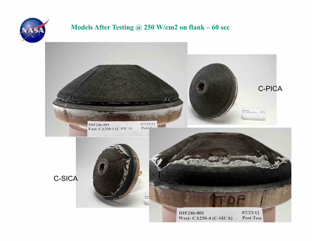
Models After Testing @ 250 W/cm2 on flank – 60 sec
C-PICA
C-SICA
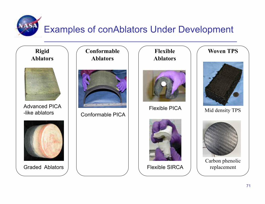
Examples of conAblators Under Development
71
Advanced PICA -like ablators Conformable PICA
Flexible SIRCA Graded Ablators
Flexible PICA
Rigid Ablators
Conformable Ablators
Flexible Ablators
Woven TPS
Mid density TPS
Carbon phenolic replacement

Completed SPRITE 250 Models

Models After Testing @ 500 W/cm2 on flank – 30 sec
C-SICA
C-PICA