thermal power plant -...
TRANSCRIPT

EI2021 Power Plant Instrumentation Department of ICE & EIE 2014-2015
St Joseph’s College Of Engineering 1 ISO 9001:2008
Thermal power plant
The general layout of the thermal Power Plant consists of mainly four circuits as shown in
fig. The four main circuits are
1. Coal and ash circuit
2. Air and Gas circuit
3. Feed water and steam flow circuit
4. Cooling water circuit
A thermal power station using steam as working fluid works basically on the Rankine
cycle. Steam is generated in a boiler, expanded in the prime mover and condensed in
condenser and fed in to the boiler again.
1) Coal and Ash circuit
In this circuit, the coal from the storage is fed to the boiler through coal handling
equipment for the generation of steam. Ash produced due to the combustion of coal is
removed to ash storage through ash handling system.
Two methods are in general use to feed the pulverised fuel to the combustion chamber of
the power plant.
i) Unit System.
ii) Central or Bin System
In unit system, each burner of the plant is fired by one or more pulverisers connected to
the burners, while in the central system, the fuel is pulverised in the central plant and then
distributed to each furnace with the help of high pressure air content.
General layout of coal handling system

EI2021 Power Plant Instrumentation Department of ICE & EIE 2014-2015
St Joseph’s College Of Engineering 2 ISO 9001:2008
Each type of fuel handling system consists of crushers, magnetic separators, driers,
pulverising mills, storage bins, conveyors and feeders. The arrangement of different
equipment required in both systems is shown in figure with the help of block diagram. The
coal received by the plant from the mine may vary widely in sizes. It is necessary to make the
coal of uniform size before passing the pulveriser for efficient grinding. The coal received
from the mine is passed through a preliminary crusher to reduce the size to allowable limit
(30mm). The crushed coal is further passed over magnetic separator which removes pyrites
and tramp iron. In a unit system, each burner or a group of burners and a pulveriser constitute
a unit. Crushed coal is fed to the pulveriser through feeder at a variable rate governed by the
combustion requirements of furnace and steam generating rate required in the boiler. In a
central feed system, the crushed coal is fed to the drier from the raw coal banker by gravity.
The drying of coal is effected either by using hot gases, preheated air or bled steam The dried
coal is fed to the pulveriser with the help of feeder. The pulverised coal is carried from the
pulveriser mill and it is separated in the cyclone separator.
Ash handling system comprises the following operations
a. To remove the ashes from the furnace ash hopper.
b. To convey the ashes from furnace ash-hopper to a storage or fill with the help of
conveyors.
c. To dispose the ashes from the storage.
The ever increasing capacities of boiler units together with their ability use low grade
high ash content coals have been responsible for the development of modern ash handling
systems. The general layout of the components used in modern ash handling and collection
plant is shown in figure. The modern ash handling systems are mainly classified into four
groups namely
• Mechanical handling system
• Hydraulic handling system
• Pneumatic handling system
• Steam jet system
The mechanical system is generally used for low capacity power plants using coal as fuel.
The hot ash coming out of boiler furnace is made to fall over the best conveyor through a
water seal.
The cooled ash falls on the best conveyor and it is carried continuously to the dumping
site or overhead bunker. The ash is carried to the dumping site from the ash bunker with the
help of trucks. The hydraulic ash handling system carries the ash with the flow of water.
With high velocity through a channel and finally dumped to the sump. The pneumatic ash
handling system is more suitable to the boiler plants from which ash and soot must be
transported some considerable distance for final disposal. The ash and dust from all discharge
points are picked up by a high velocity air stream created by an exhauster at the discharge
end.

EI2021 Power Plant Instrumentation Department of ICE & EIE 2014-2015
St Joseph’s College Of Engineering 3 ISO 9001:2008
General layout of ash handling and dust collection system
2) Air and Gas circuit
Air is supplied to the combustion chamber of the boiler either through Forced Draft or
Induced Draft fan or by using both. The dust from the air is removed before supplying to the
combustion chamber. A The exhaust gases carrying sufficient quantity of heat and ash are
passed through the air-heater where the exhaust head of the gases is given to the air and then
it passed through the dust collectors where most of the dust is removed before exhausting the
gases to the atmosphere through chimney.
a) Draft Systems
The purpose of draft is to supply required quantity of air for combustion and remove the
burnt products from the system. To move the air through the fuel bed and to produce a flow
of hot gases through the boiler, economizer, preheater and chimney require a difference of
pressure equal to that necessary to accelerate the burnt gases to their final velocity and to
overcome the pressure losses equivalent to pressure head. This difference of pressure
required to maintain the constant flow of air and to discharge the gases through the chimney
to atmosphere is known as draft. When the draft is produced with the help of chimney only, is
known as Natural Draft and when the draft is produced by any other means except chimney,
is known as artificial draft.
(i) Forced Draft
In a forced draft system, a blower is installed near the base of the boiler and air is forced to
pass through the furnace, flues, and economiser, air-preheater and to the stack. This draft
system is known as positive draft system or forced draft system because the pressure of air
throughout the system is above atmospheric pressure and air is forced to flow through the
system. The arrangement of the system is shown in figure.

EI2021 Power Plant Instrumentation Department of ICE & EIE 2014-2015
St Joseph’s College Of Engineering 4 ISO 9001:2008
Forced Draft
A stack or chimney is also used in this system but its function is to discharge gases high in
the atmosphere to prevent the contamination. It is not much significant for producing draft
therefore height of the chimney may not be very much.
(ii) Induced draft
In this system, the blower is located near the base of the chimney instead of near the gate.
The air is sucked in the system by reducing the pressure through the system below
atmosphere. The induced draft fan sucks the burned gases from the furnace and the pressure
inside the furnace is reduced below atmosphere and induces the atmospheric air to flow
through the furnace. The action of the induced draft is similar to the action of the chimney.
The draft produced is independent of the temperature of the hot gases therefore the gases may
be discharged as cold as possible after recovering as much heat as possible in air-preheater
and economiser. The fan should be located as such a place that the temperature of the gas
handled by the fan is lowest. The chimney is also used in this system and its function is
similar as in forced draft but total draft produced in induced draft system is the sum of the
drafts produced by the fan and chimney as shown is figure.
3) Feed water and Steam circuit
The steam generated in the boiler is fed to the steam prime mover to develop the power.
The steam coming out of prime mover is condensed and then fed to the boiler with the help of
pump. The condensate is heated in the feed-heaters using the steam tapped from different
points of the turbine. The feed heaters may be of mixed type or indirect heating type. Some of

EI2021 Power Plant Instrumentation Department of ICE & EIE 2014-2015
St Joseph’s College Of Engineering 5 ISO 9001:2008
the steam and water is lost passing through different components of the system therefore,
feed water is supplied from external source to compensate this loss. The feed water supplied
from external source is passed through the purifying plant to reduce the dissolved salts to an
acceptable level. The purification is necessary to avoid the scaling of the boiler tubes.
a) Economisers
The economiser is a feed water heater deriving heat from the flue gases discharged from the
boiler. The justifiable cost for-economiser depends on the total gain in efficiency. In turn, this
depends on the gas temperature going out of the boiler and feed water temperature to the
boiler. Regenerative cycle inherently gives high feed Water temperature therefore the
adoption of economiser must be known. A typical return bend type economiser is ask shown
in figure
Return bend economiser
b) Air Pre-heaters
The heat carried with the flue gases coming out of economiser is further utilised for
preheating the air before supplying to the combustion chamber. It has been found that an
increase of 20°c in the air temperature increases the boiler efficiency by 1%. It is also as
necessary equipment for supply of hot air for drying the coal in pulverised fuel systems to
facilitate grinding and satisfactory combustion of fuel in the furnace.
Tubular air preheater
EI2021 Power Plant Instrumentation Department of ICE & EIE 2014-2015
St Joseph’s College Of Engineering 6 ISO 9001:2008
A typical arrangement of tubular air-preheater is shown is figure. The flue gases flow
through the tubes and air is passed over the outer surface of the tubes as shown in figure. The
horizontal baffles are provided to increase, the time of contact while will help for higher heat
transfer. In some design, tube-row staggering is used to improve the air-distribution
b) Cooling water circuit
The quantity of cooling water required to condense the steam is considerably large and it
is taken either from lake, river or sea. The cooling water is taken from the upper side of river,
it is passed through the condenser and heated water is discharged to the lower side of the
river. Such system of cooling water supply is possible if adequate cooling water is available
throughout the year. This system is known as open system. When the adequate water is not
available, then the water coming out from the condenser is cooled either in cooling pond or
cooling tower. The cooling is done by partly evaporating the water. When the cooling water
coming out of the condenser is cooled again and supplied to the condenser, then the system is
known as closed system.
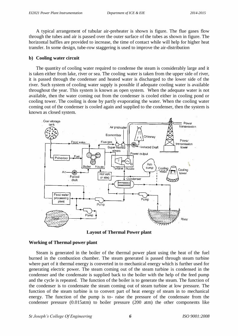
Layout of Thermal Power plant
Working of Thermal power plant
Steam is generated in the boiler of the thermal power plant using the heat of the fuel
burned in the combustion chamber. The steam generated is passed through steam turbine
where part of it thermal energy is converted in to mechanical energy which is further used for
generating electric power. The steam coming out of the steam turbine is condensed in the
condenser and the condensate is supplied back to the boiler with the help of the feed pump
and the cycle is repeated. The function of the boiler is to generate the steam. The function of
the condenser is to condensate the steam coming out of steam turbine at low pressure. The
function of the steam turbine is to convert part of heat energy of steam in to mechanical
energy. The function of the pump is to- raise the pressure of the condensate from the
condenser pressure (0.015atm) to boiler pressure (200 atm) the other components like

EI2021 Power Plant Instrumentation Department of ICE & EIE 2014-2015
St Joseph’s College Of Engineering 7 ISO 9001:2008
economizer, superheater and steam feed heaters (steam from different points of turbine is fed
to the heaters to heat the condensate to a higher temperature) are used in the primary circuit
to increase the overall efficiency of the thermal power plant.
Hydro power plant
In hydro-electric plants, potential energy of water is converted in to kinetic energy first
passing through the tunnel to the power house. The Kinetic energy of the water is converted
in to mechanical energy in the water turbines. The mechanical energy of the water turbine is
further utilized to the electric generator. This is the common principle of hydroelectric
generation. The load on the generator fluctuates according to the demand, therefore, the
mechanical power developed by the turbine must also change and that is controlled by the
governer by changing the quantity of water supplied to the turbine.
Components used in Hydro-Electric Power Plant
1) Reservoir
2) Dam
3) Trash rack
4) Forebay
5) Surge Tank
6) Penstock
7) Spill way
8) Power House
9) Prime movers.
10) Draft tube
The functions of different components used in hydroelectric power plant are described
below:
1. Reservoir
The main Purpose of the reservoir is to store the water during rainy season and supply the
same during dry season
2. Dam
The function of the dam is to increase the height of the water level behind it, which
ultimately increases the reservoir capacity. The dam also helps to increase the working head
of the power plant. Many times high dams are built only to provide the necessary head to the
power plant.
3. Trash Rack
The water intakes from the dam or from the forebay are provided with trash rack to
prevent the entry of debris which might damage the wicket gates and turbine runners or
choke-up the nozzles of the impulse turbine. If the winters are severe, special provision is
made to prevent the trouble from ice. To prevent ice from clinging to the trash racks, they are
often heated electrically. Sometimes an air bubbling system is provided in the vicinity of the
trashrack which brings warmer water to the surface of trashracks.

EI2021 Power Plant Instrumentation Department of ICE & EIE 2014-2015
St Joseph’s College Of Engineering 8 ISO 9001:2008
4. Forebay
The forebay serves as regulating reservoir temporarily storing water when the load on the
plant is reduced and provides water for initial increment of an increasing load while water in
the canal is being accelerated. In many cases, the canal itself may be large enough to absorb
the flow variations. If the canal is long, its end is sometimes enlarged to provide necessary
temporary storage. In short, forebay is a naturally provided storage which is able to absorb
the flow variations. This can be considered as naturally provided surge tank as it does the
work of surge tank. The forebay is always provided with some type of outset structure to
direct water to the penstock depending l upon local conditions.
5. Surge Tank
Surge tank is introduced in the system between the dam and power house nearest to the
power house, and preferably on the high ground to reduce the height of the tower to provide
better regulation of water pressure in the system during variable load conditions. When the
turbine gates are partly closed and water flow in to the turbine is reduced suddenly, water
rises in the surge tank.
Schematic of Hydroelectric power plant
This produces a retarding head and decreases the velocity of water in the penstock. When
the velocity of the water in the penstock is reduced to the value demanded by the turbine, the
level of the water in the surge tank starts falling and fluctuates up and down till its motion is
damped out by friction. When there is sudden rise in the load on the turbine, additional water
is supplied from surge tank. This lowers the water surface in the surge tank thus producing an
accelerating head which increases the flow of water in the penstock. When the discharge of
water corresponds to the turbine demand, the water surface in the tank ceases to fall. The
surge tank thus helps in stabilizing the velocity and pressure in penstock and reduces the
water hammer effect.

EI2021 Power Plant Instrumentation Department of ICE & EIE 2014-2015
St Joseph’s College Of Engineering 9 ISO 9001:2008
6. Penstock
A pipe between the surge tank and prime-mover is known as penstock. A The structural
design of the penstock is some as for any other pipe except it has to bear very high pressure
on inside surface during decreased load conditions on generator and on onside surface during
increased load conditions of generator. In very cold weather conditions, it is sometimes
advised to bury the penstock to present the ice formation is the pipe and to reduce the number
of expansion joints required. Uncovered penstocks are usually more expensive because of the
expansion joints, anchors and other apparatus required but they have the advantage of being
accessible for inspection and repairs.
7. Spillway
A Spillway is considered a safety valve for a dam. It must have the capacity to discharge
major floods without damage to the dam and at the same time keeps the reservoir level below
some predetermined maximum level.
8. Power House
A power house consists of two main parts, a sub-structure to support the hydraulic and
electric equipment and superstructure to house and protect this equipment. The elevation of
the turbine with respect to the tail water level is determined by the necessity of avoiding
cavitation. It is always advantageous to locate the power houses underground under certain
topographic conditions where there is no convenient site for conventional type.
9. Prime Movers
The main purpose of the prime movers is to convert the kinetic energy of water in to
mechanical energy to produce electric energy. The prime movers which are in common use
are Pelton turbine, Francis turbine, Kaplan turbine and Propeller turbines.
10. Draft tube
The draft tube is essential part of reaction turbine installation. It supplements the action of
the runner by utilising most of the remaining kinetic energy of the water at the discharge end
of the runner. The draft tube is a diverging discharge passage connecting the running with
tailrace. It is shaped to decelerate the flow with a minimum loss so that the remaining kinetic
energy of water coming out of runner is efficiently regained by converting in to suction head,
thereby increasing the total pressure difference on the runner. This regain of kinetic energy of
water coming out from reaction turbine is the primary function of the draft tube.
Nuclear power plant
Nuclear fission is the splitting of the nucleus of an atom into parts (lighter nuclei) often
producing free neutrons and other smaller nuclei, which may eventually produce photons (in
the form of gamma rays). Fission of heavy elements is an exothermic reaction which can
release large amounts of energy both as electromagnetic radiation and as kinetic energy of the
fragments (heating the bulk material where fission takes place). Fission is a form of elemental
transmutation because the resulting fragments are not the same element as the original atom.

EI2021 Power Plant Instrumentation Department of ICE & EIE 2014-2015
St Joseph’s College Of Engineering 10 ISO 9001:2008
The arrangement for pressurized water reactor is shown in figure. A pressure water
reactor is light weight water cooled and moderated reactor. It uses enriched Uranium as fuel.
The pressuring tank include4d in the circuit maintains the constant pressure in the circuit
throught the load range. Electric heating coil in the pressurizer boils the water to form the
steam which is collected in the dome and pressurizer the entire coolant circuit before starting
the reactor. To reduce the pressure, water spray is used to condense the steam. The fuel which
is generally used is UO2. The Uranium oxide is highly resistant to irradiation damage and is
very well adapted to the high burn-ups. It is also highly resistant to corrosion to high pressure
water in the event if a brake-up in the fuel cladding.
The water in the primary circuit gets heated by absorbing the fission energy in the
reactor core and same energy is given in the heat exchanger to generate the steam. The water
coming out of the heat exchanger is circulated by the pump to maintain the pressure in the
circuit in the range of 100 to 130 atm. The water becomes radioactive in passing through the
reactor; therefore, the entire primary circuit including steam generator (heat exchanger) must
be shielded to protect the operating persons. The radioactive coolant does not make the steam
radioactive in the boiler.
Components used in Nuclear Reactor
1. Reactor Core
2. Moderator
3. Reflector
4. Coolant system
6. Control rods
7. Biological shield
8. Boiler
9. Turbine
10. Generator
11. Condenser
Figure Pressurized water reactor nuclear power plant
EI2021 Power Plant Instrumentation Department of ICE & EIE 2014-2015
St Joseph’s College Of Engineering 11 ISO 9001:2008
The principle component of a nuclear power plant is its nuclear reactor made up of the
following:
a) Core is main part, in which nuclear reaction takes place and heat energy is released.
b) Moderator is required to slowdown the fast moving neutrons so as to utilise them for
fission.
c) Coolant system 'transfers heat from the-reactor core to the feed water.
d) Control system is provided for controlling the release of energy due to fission.
e) Reflector is provided to reflect back unused neutrons in to the core for improving the
neutron economy of the reactor.
f) Reactor vessel is a strong walled-container housing the core for the reactor.
g) Biological shield is provided to protect the personnel against radiation hazards.
1. Reactor Core
The core consists of large number of fuel tubes in which nuclear fuel is placed in the form
of Uranium or Plutonium rods clad with a hermetically sealed metal jacket. The fuel rods are
referred to as fuel elements. It is in these rods that the nuclear reaction takes place and large
amount of heat is released in the process. There may be as many as a few thousand fuel
elements in the core. The reactor core is shaped either cubical or cylindrical to facilitate the
coolant circulation through the core. The core has a series of parallel fuel elements in the
form of plates or rods with arrangement for axial flow of the coolant.
2. Moderator
The core accommodates a neutron moderator which is used to moderate reduce the
neutron speed to a critical value that increases the chances of fission. Chain reaction produces
fast moving neutrons which do not effectively use fission of U235 and try to escape from the
reactor. To improve the utilisation of neutrons their speed is reduced. It is done by colliding
them with material having light weight nucleus so that on collision it does not absorb the
neutron but scatters them. Such a material is called ‘moderator’. Three commonly used
moderators are graphite, heavy water and beryllium. In fast reactors, moderators are not used.
3. Control System
The control and operation of a nuclear reactor differs from the coal or oil fired furnace
where heat energy in the furnace is controlled by regulating the fuel supply. On the contrary,
a nuclear reactor is loaded with fuel which is sufficient to operate a large power plant for
several months. The consumption of this fuel and the heat generated in the reactor depends
upon the neutron flux in the reactor core. The energy produced due to chain reaction in the
core is enormous which needs a suitable control otherwise the entire core and surrounding
structure may melt destroying everything followed by radio-active pollution. This situation
would be synonymous to atom bomb explosion.
For control of chain reaction ‘control rods’ of Cadmium or Boron one accommodated in
the core which can be raised or lowered for varying the rate of disintegration. Control rods

EI2021 Power Plant Instrumentation Department of ICE & EIE 2014-2015
St Joseph’s College Of Engineering 12 ISO 9001:2008
absorb neutrons which are responsible for starting the chain reaction. Control rods insertion
in the core absorbs more neutrons and damps down the chain reaction while their withdrawal
absorbs fewer neutrons which accelerate the reaction due to increase of neutron flux. Three
control rods are divided in to three categories namely safety rods, coarse and fine regulation
rods. The safety rods are normally kept out and are inserted in the core when chain reaction in
the reactor is to be stopped for emergency reasons. As long as safety rods remain inserted in
the core there is no nuclear fission in core and consequently no power generation.
4. Reactor Vessel
It is a container accommodating the core of a power reactor, strong enough to withstand
high temperature. It also encloses the moderator, reflector, and thermal shielding and control
rods.
5. Reflector
A neutron reflector is placed around the core to minimize the leakage of neutrons. A
major part of neutrons are absorbed by the fuel rods and the unabsorbed neutrons try to
escape the reactor core. Reflector reflects back the escaping neutrons in to the core which are
used in nuclear fission thereby improving the efficiency of the reactor.
6. Biological Shield
The purpose of biological shielding is to prevent passage of radiations, such as high
neutron fluxes; alpha, beta and gamma rays and fission fragments. Radiation produced by the
reactor, either in operation or during a shutdown is required to be restricted by the shielding
to a level not to exceed the permissible one. The primary function of biological shielding is to
provide safe working conditions for operating personnel.
7. Instrumentation
Control and safety auxiliaries for a reactor are provided to measure population of
neutrons. It indicates the power level of the reactor or the rate of charge of power level. This
is measured in an ionization chamber. The chamber is filled with gas. When exposed to
neutron radiations, a current is produced which is proportional to the power level in the
reactor automatically. In case of excessive neutron population, it shuts down the reactor.
Solar power plant
a) Low temperature solar power plant (upto 100 C)
The energy of the sun is collected by water flowing through an array of flat-plate
collectors as shown in figure 1.

EI2021 Power Plant Instrumentation Department of ICE & EIE 2014-2015
St Joseph’s College Of Engineering 13 ISO 9001:2008
Figure 1. Low temperature solar power plant
To get still higher temperatures, booster mirrors which reflect radiation on to the flat-plate
collectors are arte sometimes used. The hot water at about 100 C is stored in a well-insulated
thermal storage tank. From the storage tank, it flows through a vapour generator through
which the working fluid is passed. The working fluid has a low boiling point. Consequently,
vapour at about 90°C and a pressure of a few atmospheres leaves the vapour generator. This
vapour then executes a regular cycle by flowing through a prime mover, a condenser and a
pump.
b) Medium Temperature System (above 100°C to 250°C)
It can be attained by using arrays of cylindrical parabolic focusing collectors. The axes of
these collectors could be oriented north-south or east- west and tracking about these axes
would be required. The fluid flowing through the absorber tubes is a high-boiling-point
liquid. It is stored in tanks and drawn through a heat-exchanger in which it transfers heat to
high pressure water which is converted in to steam.
c) High temperature solar power plant (above 250°C)
The central receiver tower solar power plant consists basically five sub-systems as shown
in figure 2.
The heliostat field
The sodium heat transfer system
The power conversion system
The electrical system
The data acquisition system
Figure 2. High temperature solar power plant
Heliostat array made of plastic sheets with protective coating are used to reflect sun rays
to central receiver tower (500m high). The heliostats continuously track the sun by optical
guides and focus the lower top where heat transport fluid is heated and piped to ground for
turbo generator drive. Liquid sodium is used as a cooling medium for the receiver due to its

EI2021 Power Plant Instrumentation Department of ICE & EIE 2014-2015
St Joseph’s College Of Engineering 14 ISO 9001:2008
excellent thermal transmission characteristics. Solar concentration ratio of about 1000 is
achieved with a temperature range of 480°C - 540°C which suits turbine characteristics. Such
plants are operative up to 500 kW capacities which need four acres of land for heliostats
infrastructure. Two sodium tanks are integrated in to sodium heat transfer system to form a
thermal store. A conventional Water steam circuit in conjunction with steam turbine and
generator convert which has been transferred to a steam generator by the sodium heat transfer
system in to electrical energy. The electrical system provides power to all its auxiliaries.
However an emergency diesel generator and batteries are maintained. The electric power is
fed to the grid through a transformer. A data acquisition system is maintained in the control
room for monitoring and logging normal operations and for evaluation of system studies.
d) Photo Voltaic Power Generation
Photo voltaic power generation is a method of producing electricity out of a semi-
conductor by means of a quantum effect which converts optical energy in to electrical energy
as shown in figure 3.
Figure 3. Photo voltaic power generation
If an n-type semi-conductor is brought in to contact with a p-type semiconductor a
contact potential difference will be established at the interface by the diffusion of the
electrons. With the p-type semiconductor exposed to light, its electrons absorb photons of
light and pass it to n-type region, thus generating an electric current in a closed circuit. Such
cells are Solar Cells. Solar cells can be connected in series and parallel in the form of array
on a panel to get the desired rating of voltage and current. The maximum possible rating is
250 W/m3 of array. So a power plant of 250MW needs an array surface of one square
kilometer. The solar energy is directly received by the photovoltaic cells and it can be
increased by the use of concentration and tracking system. The output of the photovoltaic
cells array is DC so it is converted into AC for local use and feeding the grid. This can be
done by suitable regulation and dispatch unit.
Wind power plant
The winds on earth surface are caused primarily by the unequal heating of the land and
water by the sun. The differences in temperature gradients induce the circulation of air from
one to another. The main components of Wind Energy Conversion System is shown (figure
1) in block diagram form.
1. Aeoroturbine
EI2021 Power Plant Instrumentation Department of ICE & EIE 2014-2015
St Joseph’s College Of Engineering 15 ISO 9001:2008
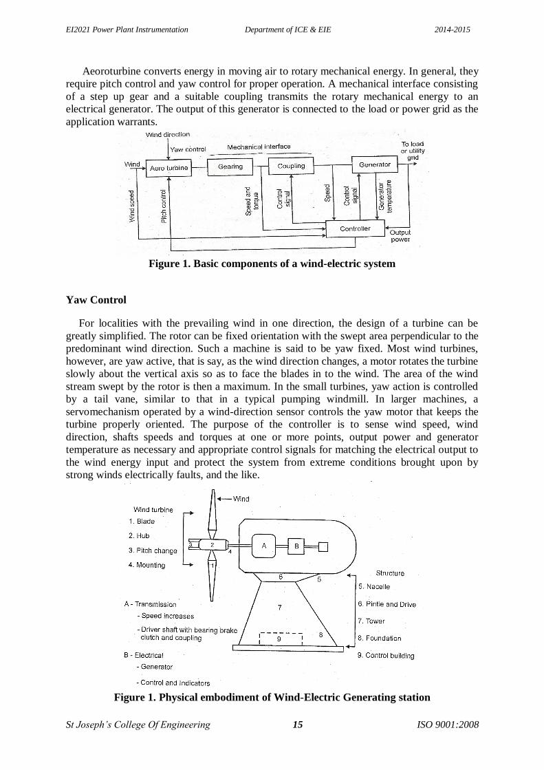
Aeoroturbine converts energy in moving air to rotary mechanical energy. In general, they
require pitch control and yaw control for proper operation. A mechanical interface consisting
of a step up gear and a suitable coupling transmits the rotary mechanical energy to an
electrical generator. The output of this generator is connected to the load or power grid as the
application warrants.
Figure 1. Basic components of a wind-electric system
Yaw Control
For localities with the prevailing wind in one direction, the design of a turbine can be
greatly simplified. The rotor can be fixed orientation with the swept area perpendicular to the
predominant wind direction. Such a machine is said to be yaw fixed. Most wind turbines,
however, are yaw active, that is say, as the wind direction changes, a motor rotates the turbine
slowly about the vertical axis so as to face the blades in to the wind. The area of the wind
stream swept by the rotor is then a maximum. In the small turbines, yaw action is controlled
by a tail vane, similar to that in a typical pumping windmill. In larger machines, a
servomechanism operated by a wind-direction sensor controls the yaw motor that keeps the
turbine properly oriented. The purpose of the controller is to sense wind speed, wind
direction, shafts speeds and torques at one or more points, output power and generator
temperature as necessary and appropriate control signals for matching the electrical output to
the wind energy input and protect the system from extreme conditions brought upon by
strong winds electrically faults, and the like.
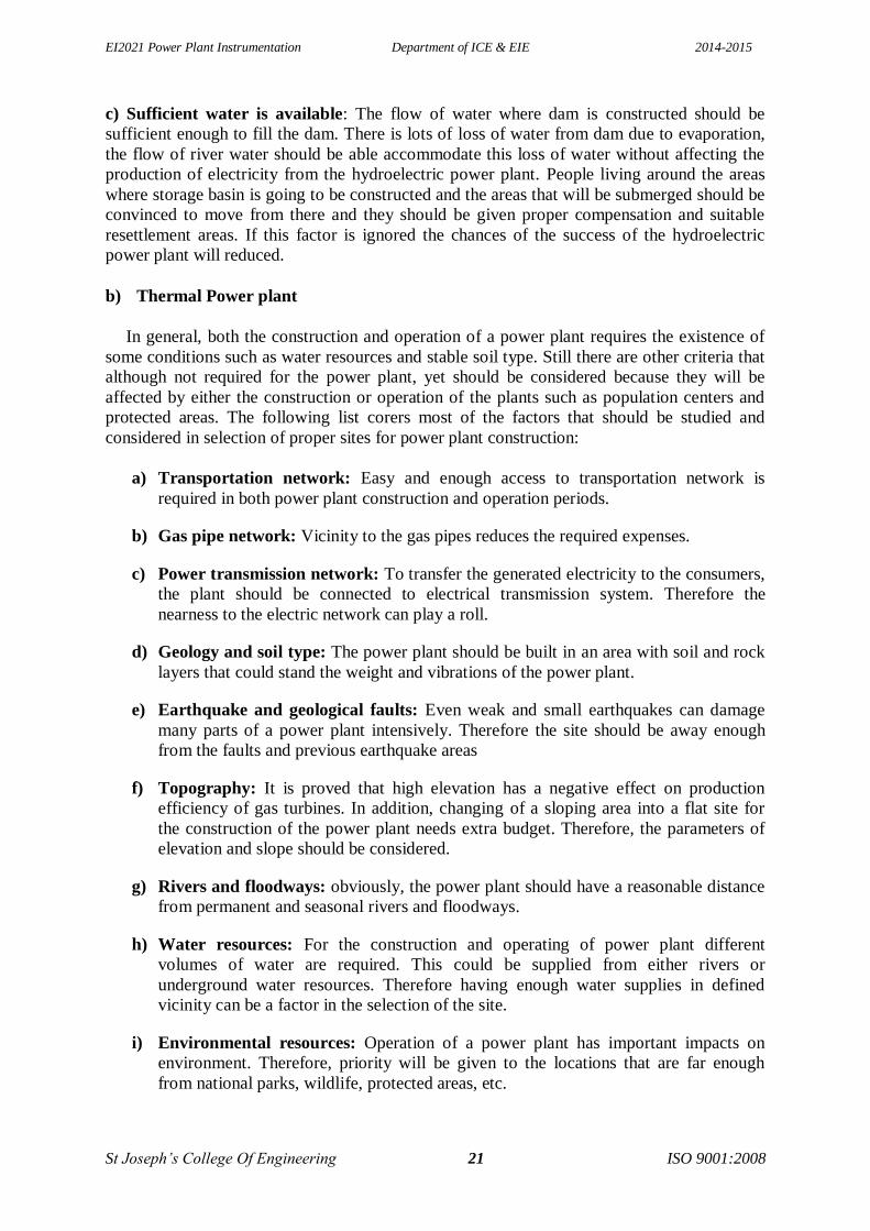
Figure 1. Physical embodiment of Wind-Electric Generating station

EI2021 Power Plant Instrumentation Department of ICE & EIE 2014-2015
St Joseph’s College Of Engineering 16 ISO 9001:2008
The physical embodiment for such an aero-generator is shown in figure 2. The sub
components of the windmill are
1) Wind turbine or rotor
2) Wind mill head
3) Transmission and control
4) Supporting structure
2. Rotors
Rotors are mainly of two types
i. Horizontal axis rotor and
ii. Vertical axis rotor
One advantage of vertical-axis machines is that they operator in all wind directions and
thus need no yaw adjustment. The rotor is only one of the important components. For an
effective utilization all the components need to be properly designed and matched with the
rest of the components.
3. Windmill head
It supports the rotor housing the rotor bearings. It also houses any control mechanism
incorporated like changing the pitch of the blades for safety devices and tail vane to orient the
rotor to face the wind. The latter is facilitated by mounting it on the top of the supporting
structure on suitable bearings.
4. Transmissions
The rate or rotation of large wind turbine generators operating at rated capacity or below
is conveniently controlled by varying the pitch of the rotor blades, but it is low, about 40 to
50 revolutions per minute (rpm). Because optimum generator output requires much greater
rates of rotation, such as 1800 rpm, it is necessary to increase greatly the low rotor rate of
turning. Among the transmission options are mechanical systems involving fixed ratio gears,
belts and chains, singles or in combination or hydraulic systems involving fluid pumps and
motors. Fixed ratio gears are recommended for top mounted equipment because of their high
efficiency, known cost and minimum system risk. For bottom mounted equipment which
requires a right-angle drive, transmission costs might be reduced substantially by using large
diameter bearings with ring gears mounted on the hub to serve as a transmission to increase
rotor speed to generator speed. Such a combination offers a high degree of design flexibility
as well as large potential savings.
5. Generator
Either constant or variable speed generators are a possibility, but variable speed units are
expensive and/or unproved. Among the constant speed generator candidates for use are
synchronous induction and permanent magnet types. The generator of choice is the
synchronous unit for large aero generator systems because it is very versatile and has an
extensive database. Other electrical components and systems are, however, under
development.
6. Controls

EI2021 Power Plant Instrumentation Department of ICE & EIE 2014-2015
St Joseph’s College Of Engineering 17 ISO 9001:2008
The modern large wind turbine generator requires a versatile and reliable control system
to perform the following functions.
i. The orientation of the rotor in to the wind (azimuth of yaw)
ii. Startup and cut-in of the equipment
iii. Power control of the rotor by varying the pitch of the blades
iv. Generator output monitoring-status, data computation and storage
v. Shutdown and cutout owing to malfunction or very high winds
vi. Protection for the generator, the utility accepting the power and the prime mover
vii. Auxiliary and / or emergency power, and
viii. Maintenance mode
Many combinations are possible in terms of the control system and may involve the
following components.
a) Sensor: Mechanical, Electrical, or Pneumatic
b) Decision Elements: Relays, logic modulus, analog circuits, a microprocessor a fluidics,
units, or a mechanical unit; and
c) Actuators: Hydraulic, electric or pneumatic. A recommended combination of electronic
transducers feeding in to a microprocessor which, in turn, signals electrical actuators and
provides protection through electronic circuits, although a pneumatic slip clutch may be
required.
7. Towers
Four types of supporting towers deserve considerations, there are:
a) Reinforced concrete towers b) Pole tower
c) Built-up shell-type tower d) Truss tower
Among these, the truss tower is favoured because it is proved and widely adaptable, cost
is low, parts are readily available, it is readily transported, and it is potentially stiff Shell-tube
towers also have attractive features and may prove to be competitive with truss towers.
Steam power plant
Steam is an important medium of producing mechanical energy. Steam has the advantage
that, it can be raised from water which is available in abundance it does not react much with
the materials of the equipment of power plant and is stable at the temperature required in the
plant. Steam is used to drive steam engines, steam turbines etc. Steam power station is most
suitable where coal is available in abundance. Thermal electrical power generation is one of
the major methods. Out of total power developed in India about 60% is thermal. For a
thermal power plant the range of pressure may vary from 10 kg/cm2 to super critical
pressures and the range of temperature may be from 250°C to 650°C. The average all India
Plant load factor (P.L.F.) of thermal power plants in 1987-88 has been worked out to be
56.4% which is the highest P.L.F. recorded by thermal sector so far. A steam power plant
must have following equipments:
1. A furnace to burn the fuel.
2. Steam generator or boiler containing water. Heat generated in the furnace is
utilized to convert water in steam.

EI2021 Power Plant Instrumentation Department of ICE & EIE 2014-2015
St Joseph’s College Of Engineering 18 ISO 9001:2008
3. Main power unit such as an engine or turbine to use the heat energy of steam
and perform work.
4. Piping system to convey steam and water.
In addition to the above equipment the plant requires various auxiliaries and
accessories depending upon the availability of water, fuel and the service for which the
plant is intended. The flow sheet of a thermal power plant consists of the following four
main circuits:
a) Feed water and steam flow circuit
b) Coal and ash circuit
c) Air and gas circuit
d) Cooling water circuit.
A steam power plant using steam as working substance works basically on Rankine cycle.
Steam is generated in a boiler, expanded in the prime mover and condensed in the
condenser and fed into the boiler again. The different types of systems and components
used in steam power plant are as follows:
High pressure boiler
Prime mover
Condensers and cooling towers
Coal handling system
Ash and dust handling system
Draught system
Feed water purification plant
Pumping system
Air preheater, economizer, super heater, feed heaters.
Schematic arrangement of equipment of a steam power station.

EI2021 Power Plant Instrumentation Department of ICE & EIE 2014-2015
St Joseph’s College Of Engineering 19 ISO 9001:2008
Coal received in coal storage yard of power station is transferred in the furnace by coal
handling unit. Heat produced due to burning of coal is utilized in converting water contained
in boiler drum into steam at suitable pressure and temperature. The steam generated is passed
through the superheater. Superheated steam then flows through the turbine. After doing work
in the turbine die pressure of steam is reduced. Steam leaving the turbine passes through the
condenser which maintains the low pressure of steam at the exhaust of turbine. Steam
pressure in the condenser depends upon flow rate and temperature of cooling water and on
effectiveness of air removal equipment. Water circulating through the condenser may be
taken from the various sources such as river, lake or sea. If sufficient quantity of water is not
available the hot water coming out of the condenser may be cooled in cooling towers and
circulated again through the condenser. Bled steam taken from the turbine at suitable
extraction points is sent to low pressure and high pressure water heaters. Air taken from the
atmosphere is first passed through the air pre-heater, where it is heated by flue gases. The hot
air then passes through the furnace. The flue gases after passing over boiler and superheater
tubes, flow through the dust collector and then through economiser, air preheater and finally
they are exhausted to the atmosphere through the chimney. Steam condensing system consists
of the following:
Condenser
Cooling water
Cooling tower
Hot well
Condenser cooling water pump
Condensate air extraction pump
Air extraction pump
Boiler feed pump
Make up water pump.
CHARACTERISTICS OF STEAM POWER PLANT
The desirable characteristic for a steam power plant are as follows:
Higher efficiency.
Lower cost.
Ability to burn coal especially of high ash content and inferior coals.
Reduced environmental impact in terms of air pollution.
Reduced water requirement.
Higher reliability and availability.
Instrumentation in power generation
Importance of instrumentation in power generation
1) Instruments used in power plants furnish accurate i n for guidance to safe, continuous and
proper plant operation.
2) The information given by the recording units from the control room helps to direct its
operation so as to achieve the best performance and furnish data for calculation so that
results may be compared from time to time. There may be used to check on the internal
condition of equipment and indicate when and where maintenance is needed.
3) The functions of instruments to be performed for

EI2021 Power Plant Instrumentation Department of ICE & EIE 2014-2015
St Joseph’s College Of Engineering 20 ISO 9001:2008
i. Operating Guidance
ii. Performance calculations
iii. Maintenance and repair guidance
iv. Economical Supervision
v. Pressure and temperature measurements of steam and feed water
vi. Flow measurement
vii. Drum level measurement
viii. CO2 Indication
ix. Air flow recording
x. Flue Gas Analysis
xi. Electrical parameters indication ,
xii. With the introduction of modern type power plants, there is tendency towards
remote control of power plant equipment.
Factors to be considered while selecting the power plant
a) Hydroelectric power plant
Issues with Dams
The dam also called as water reservoir is the most important part of the hydroelectric
power plants. All the water that is used for generation of electricity in the hydroelectric power
plants is stored in the dam. Since huge quantities of water are stored in the dam, it is very
important that the bed and walls of the dam should be able to sustain all the hydraulic
pressures of water. Water has mass and large quantities of water have huge weight which is
exerted on the bed and the walls of the dam. If the walls of the dam are not strong enough to
sustain the forces of water, the walls will break and water will spread to the surrounding areas
producing devastating floods that have potential to cause large scale destruction of human,
animal and plant life.
Factors Affecting the Selection of Site for Dams
Apart from the construction of the dam, selecting proper site for the dam is very crucial.
Selecting the proper site will help carrying out construction of the strong dam and it will also
help reduce risks due to natural disasters like earth quake. Here are some of the important
factors to be considered while selecting the site for the dam for hydroelectric power plants:
a) Good topographical location along the path of river: The best location along the path of
the river is river canyon or at the location where there is narrowing of the river. If the aim is
to store maximum amount of water, then the volume of basin above dam should be calculated
so that sufficient quantity of water can be stored in it. The perfect site is one where there is
wide and flat valley.
b) Right geological structure: The rock structure on which the dam will be constructed
should be strong enough to sustain the weight of dam and water stored in the dam. The rock
structure should be able to sustain all the visible and invisible forces. The rock structure
should be stable and there should be least occurrence of the earthquakes in the region. The
rock structure should not allow the seepage of water and it should be waterproof.
EI2021 Power Plant Instrumentation Department of ICE & EIE 2014-2015
St Joseph’s College Of Engineering 21 ISO 9001:2008
c) Sufficient water is available: The flow of water where dam is constructed should be
sufficient enough to fill the dam. There is lots of loss of water from dam due to evaporation,
the flow of river water should be able accommodate this loss of water without affecting the
production of electricity from the hydroelectric power plant. People living around the areas
where storage basin is going to be constructed and the areas that will be submerged should be
convinced to move from there and they should be given proper compensation and suitable
resettlement areas. If this factor is ignored the chances of the success of the hydroelectric
power plant will reduced.
b) Thermal Power plant
In general, both the construction and operation of a power plant requires the existence of
some conditions such as water resources and stable soil type. Still there are other criteria that
although not required for the power plant, yet should be considered because they will be
affected by either the construction or operation of the plants such as population centers and
protected areas. The following list corers most of the factors that should be studied and
considered in selection of proper sites for power plant construction:
a) Transportation network: Easy and enough access to transportation network is
required in both power plant construction and operation periods.
b) Gas pipe network: Vicinity to the gas pipes reduces the required expenses.
c) Power transmission network: To transfer the generated electricity to the consumers,
the plant should be connected to electrical transmission system. Therefore the
nearness to the electric network can play a roll.
d) Geology and soil type: The power plant should be built in an area with soil and rock
layers that could stand the weight and vibrations of the power plant.
e) Earthquake and geological faults: Even weak and small earthquakes can damage
many parts of a power plant intensively. Therefore the site should be away enough
from the faults and previous earthquake areas
f) Topography: It is proved that high elevation has a negative effect on production
efficiency of gas turbines. In addition, changing of a sloping area into a flat site for
the construction of the power plant needs extra budget. Therefore, the parameters of
elevation and slope should be considered.
g) Rivers and floodways: obviously, the power plant should have a reasonable distance
from permanent and seasonal rivers and floodways.
h) Water resources: For the construction and operating of power plant different
volumes of water are required. This could be supplied from either rivers or
underground water resources. Therefore having enough water supplies in defined
vicinity can be a factor in the selection of the site.
i) Environmental resources: Operation of a power plant has important impacts on
environment. Therefore, priority will be given to the locations that are far enough
from national parks, wildlife, protected areas, etc.

EI2021 Power Plant Instrumentation Department of ICE & EIE 2014-2015
St Joseph’s College Of Engineering 22 ISO 9001:2008
j) Population centers: For the same reasons as above, the site should have an enough
distance from population centers.
k) Need for power: In general, the site should be near the areas that there is more need
for generation capacity, to decrease the amount of power loss and transmission
expenses.
l) Climate: Parameters such as temperature, humidity, wind direction and speed affect
the productivity of a power plant and always should be taken into account.
m) Land cover: Some land cover types such as forests, orchard, agricultural land,
pasture are sensitive to the pollutions caused by a power plant. The effect of the
power plant on such land cover types surrounding it should be counted for.
n) Area size: Before any other consideration, the minimum area size required for the
construction of power plant should be defined.>
o) Distance from airports: Usually, a power plant has high towers and chimneys and
large volumes of gas. Consequently for security reasons, they should be away from
airports.
p) Archaeological and historical sites: Usually historical building …are fragile and at
same time very valuable. Therefore the vibration caused by power plant can damage
them, and a defined distance should be considered.
c) Nuclear Power plant
Site selection and evaluation are a crucial part of establishing a nuclear power programme
and can be significantly affected by costs and public acceptance. While site selection of a
nuclear power plant, the aim is to protect the plant against external threats as well as to
minimize any environmental detriments and threats that might arise from it. Some important
factors while site selection:
a) Use of land and water area: Construction is not allowed on shore zones belonging to the
coastal area of a sea or of a water system which would otherwise affect ecology.
b) Availability of nuclear fuel, cooling water: The site should be such that the fuel
required for nuclear power generation such as uranium and others should be available
near the site or transporting such fuel should not be difficult and time consuming. Also
PWR, BWR mostly use light water H2O as their coolant as well as moderator so water
facility should be available near to the site and in plenty.
c) Population and sources of livelihood in the region: A nuclear power plant site extends
to about a kilometers’ distance from the facility. It is defined as an area where only power
plant related activities are allowed as a rule. Permanent settlement is prohibited and only
very limited employee accommodation or recreational settlement is allowed.
d) Human activities and human facilities: In the plant’s vicinity there may not be facilities
or population centres where the necessary protective measures, such as sheltering indoors
or evacuation, would be difficult to implement. In the plant’s vicinity, no activities may
be carried out that could pose an external threat to the plant. The general principle in the
EI2021 Power Plant Instrumentation Department of ICE & EIE 2014-2015
St Joseph’s College Of Engineering 23 ISO 9001:2008
siting of nuclear power plants is to have the facilities in a sparsely populated area and far
away from large population centres. What justifies placement in a sparsely populated area
is that emergency planning will then be directed at a smaller population group and will
thus be easier to implement. The licensee responsible for the operation of the nuclear
power plant shall have authority of decision over all activities in the area and shall be able
to remove unauthorized individuals from the site, if necessary, or prevent such individuals
from entering it. The plant site may contain other non- facility related activities provided
that they do not pose a threat to plant safety.
e) External threats and environmental threats: Examples of exceptional
natural phenomena include
Freezing or other clogging of the cooling water intake
Storms
Flood
f) Seismic area evaluation: Earthquake is a biggest threat to nuclear power plant and
hazardous accidents might take place if the earthquake strikes the site.
g) Transport arrangements and Traffic arrangements: Transport system to the plant
should be smooth and should not affect the working of plant due to delays in transporting
necessary material, men etc to the plant. A traffic lane may traverse the site if the volume
of traffic is small.
Boiler
Boiler is an apparatus to produce steam. Thermal energy released by combustion of
fuel is transferred to water, which vaporizes and gets converted into steam at the desired
temperature and pressure. The steam produced is used for:
Producing mechanical work by expanding it in steam engine or steam turbine.
Heating the residential and industrial buildings
Performing certain processes in the sugar mills, chemical and textile industries.
Boiler is a closed vessel in which water is converted into steam by the application of heat.
Usually boilers are coal or oil fired. A boiler should fulfill the following requirements
1) Safety. The boiler should be safe under operating conditions.
2) Accessibility. The various parts of the boiler should be accessible for repair and
maintenance.
3) Capacity. The boiler should be capable of supplying steam according to the
requirements.
4) Efficiency. To permit efficient operation, the boiler should be able to absorb a
maximum amount of heat produced due to burning of fuel in the furnace.
5) It should be simple in construction and its maintenance cost should be low.
6) Its initial cost should be low.
7) The boiler should have no joints exposed to flames.
8) The boiler should be capable of quick starting and loading. The performance of a
boiler may be measured in terms of its evaporative capacity also called power of a
boiler. It is defined as the amount of water evaporated or steam produced in kg per

EI2021 Power Plant Instrumentation Department of ICE & EIE 2014-2015
St Joseph’s College Of Engineering 24 ISO 9001:2008
hour. It may also be expressed in kg per kg of fuel burnt or kg/hr/m2 of heating
surface.
HIGH PRESSURE BOILERS
In all modern power plants, high pressure boilers (> 100 bar) are universally used as
they offer the following advantages. In order to obtain efficient operation and high capacity,
forced circulation of water through boiler tubes is found helpful. Some special types of
boilers operating at super critical pressures and using forced circulations are described in this
chapter.
a) The efficiency and the capacity of the plant can be increased as reduced quantity of steam
is required for the same power generation if high pressure steam is used.
b) The forced circulation of water through boiler tubes provides freedom in the arrangement
of furnace and water walls, in addition to the reduction in the heat exchange area.
c) The tendency of scale formation is reduced due to high velocity of water.
d) The danger of overheating is reduced as all the parts are uniformly heated.
e) The differential expansion is reduced due to uniform temperature and this reduces the
possibility of gas and air leakages.
f) Some special types of high pressure supercritical boilers are described in this chapter.
LA MONT BOILER
A forced circulation boiler was first introduced in 1925 by La Mont. The arrangement
of water circulation and different components are shown in Fig. The feed water from hot well
is supplied to a storage and separating drum (boiler) through the economizer. Most of the
sensible heat is supplied to the feed water passing through the economizer. A pump circulates
the water at a rate 8 to 10 times the mass of steam evaporated. This water is circulated
through the evaporator tubes and the part of the vapour is separated in the separator drum.
The large quantity of water circulated (10 times that of evaporation) prevents the tubes from
being overheated. The centrifugal pump delivers the water to the headers at a pressure of 2.5
bar above the drum pressure.

EI2021 Power Plant Instrumentation Department of ICE & EIE 2014-2015
St Joseph’s College Of Engineering 25 ISO 9001:2008
The distribution headers distribute the water through the nozzle into the evaporator.
The steam separated in the boiler is further passed through the super-heater. Secure a uniform
flow of feed water through each of the parallel boiler circuits a choke is fitted entrance to
each circuit. These boilers have been built to generate 45 to 50 tons of superheated steam at a
pressure of 120 bars and temperature of 500°C. Recently forced circulation has been
introduced in large capacity power.
BENSON BOILER
The main difficulty experienced in the La Mont boiler is the formation and attachment
of bubbles on the inner surfaces of the heating tubes. The attached bubbles reduce the heat
flow and steam generation as it offers higher thermal resistance compared to water film 1.
Benson in 1922 argued that if the boiler pressure was raised to critical pressure (225 atm.),
the steam and water would have the same density and therefore the danger of bubble
formation can be completely 2. Natural circulation boilers require expansion joints but these
are not required for Benson as the pipes are welded. The erection of Benson boiler is easier
and quicker as all the parts are welded at site and workshop job of tube expansion is
altogether avoided. 3. The transport of Benson boiler parts is easy as no drums are required
and majority of the parts are carried to the site without pre-assembly. 4. The Benson boiler
can be erected in a comparatively smaller floor area. The space problem does not control the
size of Benson boiler used. 5. The furnace walls of the boiler can be more efficiently
protected by using small diameter and close pitched tubes. 6. The superheater in the Benson
boiler is an integral part of forced circulation system, therefore no special starting
arrangement for superheater is required. 7. The Benson boiler can be started very quickly
because of welded joints. 8. The Benson boiler can be operated most economically by
varying the temperature and pressure at partial loads and overloads. The desired temperature
can also be maintained constant at any pressure. 9. Sudden fall of demand creates circulation
problems due to bubble formation in the natural circulation boiler which never occurs in
Benson boiler. This feature of insensitiveness to load fluctuations makes it more suitable for
grid power station as it has better adaptive capacity to meet sudden load fluctuations. 10. The
blow-down losses of Benson boiler are hardly 4% of natural circulation boilers of same
capacity. 11. Explosion hazards are not at all severe as it consists of only tubes of small
diameter and has very little storage capacity compared to drum type boiler. During starting,
the water is passed through the economiser, evaporator, superheater and back to the feed line
via starting valve A. During starting the valve B is closed. As the steam generation starts and
it becomes superheated, the valve A is closed and the valve B is opened. During starting, first
circulating pumps are started and then the burners are started to avoid the overheating of
evaporator and superheater tubes.
LOEFFLER BOILER
The major difficulty experienced in Benson boiler is the deposition of salt and
sediment on the inner surfaces of the water tubes. The deposition reduced the heat transfer
and ultimately the generating capacity. This further increased the danger of overheating the
tubes due to salt deposition as it has high thermal resistance. The difficulty was solved in
Loeffler boiler by preventing the flow of water into the boiler tubes. Most of the steam is
generated outside from the feedwater using part of the superheated steam coming out from
the boiler. The pressure feed pump draws the water through the economiser and delivers it
into the evaporator drum as shown in the figure. About 65% of the steam coming out of

EI2021 Power Plant Instrumentation Department of ICE & EIE 2014-2015
St Joseph’s College Of Engineering 26 ISO 9001:2008
superheater is passed through the evaporator drum in order to evaporate the feed water
coming from economiser. The steam circulating pump draws the saturated steam from the
evaporator drum and is passed through the radiant superheater and then connective
superheater. About 35% of the steam coming out from the superheater is supplied to the H.P.
steam turbine. The steam coming out from H.P. turbine is passed through reheater before
supplying to L.P. turbine as shown in the figure. The amount of steam generated in the
evaporator drum is equal to the steam tapped (65%) from the superheater. The nozzles which
distribute the superheated steam through the water into the evaporator drum are of special
design to avoid priming and noise. This boiler can carry higher salt concentration than any
other type and is more compact than indirectly heated boilers having natural circulation.
These qualities fit it for land or sea transport power generation. Loeffler boilers with
generating capacity of 94.5 tons/hr and operating at 140 bars have already been
commissioned.
P & I Diagram of Boiler
Co-generation
Co-generation is the combined production of two forms of useful energy from the same
fuel. In industry, two forms of required useful energy are thermal and Co-generation
systems are sequential in nature because the exhaust from producing one form of energy is
used as input for producing the next form of energy. In co-generation system, high pressure
steam is used for generating the power and the exhaust steam is used in manufacturing
processes. The efficiency of co-generation system is as high as 85% whereas the efficiency of
steam power plant is hardly 40%. The higher efficiency in the conversion of fuel in to useful
energy translates in to a substantial reduction in pollution and reduction in the energy costs
associated with production operations.
EI2021 Power Plant Instrumentation Department of ICE & EIE 2014-2015
St Joseph’s College Of Engineering 27 ISO 9001:2008
Co-generation is most often used in industrial units requiring significant amounts of
thermal energy and electricity and where the ratios of forms of energy are favourable towards
combined production of thermal and mechanical energy.
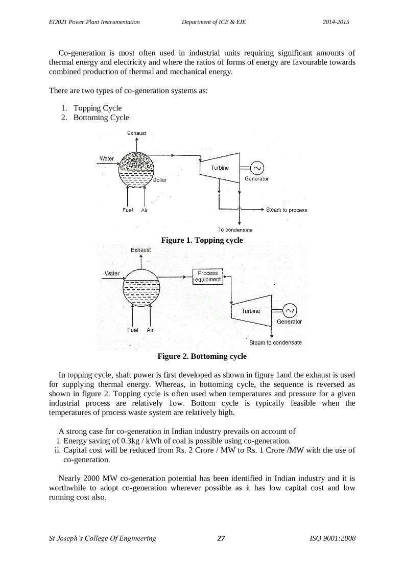
There are two types of co-generation systems as:
1. Topping Cycle
2. Bottoming Cycle
Figure 1. Topping cycle
Figure 2. Bottoming cycle
In topping cycle, shaft power is first developed as shown in figure 1and the exhaust is used
for supplying thermal energy. Whereas, in bottoming cycle, the sequence is reversed as
shown in figure 2. Topping cycle is often used when temperatures and pressure for a given
industrial process are relatively 1ow. Bottom cycle is typically feasible when the
temperatures of process waste system are relatively high.
A strong case for co-generation in Indian industry prevails on account of
i. Energy saving of 0.3kg / kWh of coal is possible using co-generation.
ii. Capital cost will be reduced from Rs. 2 Crore / MW to Rs. 1 Crore /MW with the use of
co-generation.
Nearly 2000 MW co-generation potential has been identified in Indian industry and it is
worthwhile to adopt co-generation wherever possible as it has low capital cost and low
running cost also.