thermal modelling of the wing anti ice system in modern ... · thermal modelling of the wing anti...
TRANSCRIPT

Thermal modelling of the Wing Anti Ice System in modern aircrafts
D. Labuhn1 & M. Logeais2 1Thermal Technology Centre, Airbus, Bremen, Germany 2Ice & Rain Protection Systems, Airbus, Toulouse, France
Abstract
An overview is provided on the way of working and on the problems that are frequently encountered when modelling the parts of the aircraft wing structure, which are exposed to elevated temperatures caused by the activation of the Wing Anti Ice System (WAIS). The aim of this paper is to highlight the exchange of simulation results such as heat transfer coefficients between two different groups with different scopes rather than presenting the values obtained. The WAIS is a means to protect the aerodynamic surfaces from ice-accretion by heating. The heating is applied to those areas that are most sensitive to a change of their aerodynamic properties. This is most important for the slats, which are located in the wing leading edge and represent the stagnation point for the flow field where small changes in the external shape strongly impact aerodynamic properties such as lift and drag. As heating source, hot bleed air from the engines is blown into the slats, the air temperature is first reduced to around 200°C by means of the pre-cooler and then distributed inside the slat by the so called piccolo tube. The thermal analysis of the heated slat requires special attention, as internal parameters like the supply pressure and temperature will vary as well as external conditions like the ambient temperature and the heat transfer coefficients. The allowed range for the slat temperature is limited by the system requirements for anti-icing performance and by the structural capability taking into account the structural strength reduction at elevated temperatures. Keywords: WAIS Wing Anti Ice System, transient thermal analysis, aircraft, CFD mapping, boundary conditions.
Advanced Computational Methods and Experiments in Heat Transfer XII 305
doi:10.2495/HT120261
www.witpress.com, ISSN 1743-3533 (on-line) WIT Transactions on Engineering Sciences, Vol 75, © 201 WIT Press2

1 Introduction
Slats are movable parts at the leading edge of an aircraft wing. This position makes the maintenance of the external shape extremely important due to aerodynamic considerations. As the build-up of an ice-layer would lead to unwanted change in the lift and drag behaviour, this has to be prevented under all circumstances. This text gives an insight into the industrial approach at Airbus to demonstrate thermal integration of the anti-icing system inside the slat, as shown in Figure 1.
Figure 1: Slat location on wing and typical slat design.
Results derived by thermal analyses of slats with activated anti icing system are driven by two main sets of boundary conditions. The slat internal boundary conditions are heat transfer coefficients and reference temperatures derived by the system team by means of Computational Fluid Dynamics (CFD) for the internal flow field, shown in Figure 2. The slat external boundary conditions are the local heat transfer coefficients towards the ambient air and the reference temperature of the ambient air that is computed from the outside air temperature and the Mach number and also the radiation like sunlight, sky radiation and earth albedo are taken into account. In order to correctly predict the structure temperature input from both sides an adequate level of accuracy is required. The exchange of information between the
306 Advanced Computational Methods and Experiments in Heat Transfer XII
www.witpress.com, ISSN 1743-3533 (on-line) WIT Transactions on Engineering Sciences, Vol 75, © 201 WIT Press2

CFD code and the thermal model, the way of working to enable this exchange and the subsequent thermal analyses are outlined in the following sections.
2 Design process of the WAIS
The steps in the design process are described with special focus on the data exchange between the team designing the system on the one hand and the team designing the structure that the system is installed into on the other hand and how the two sides depend on and influence each other. This is done in the following sections following the standard order of events in the Airbus industrial context.
2.1 Definition of WAIS design
The slats are supplied with conditioned engine bleed air via a single valve. The air mass flow is regulated versus the altitude and is delivered via a telescopic duct at one end of the slat . The ice protected slat is subdivided internally into fore and aft cavities (D-bay and Aft-bay) by the front spar, see Figure 2.
Figure 2: Slat cross section with internal flow field.
The hot air is distributed span wise to the point of use via a piccolo tube running along the length of each slat within the D-bay. The anti-ice effect is achieved using heating single skins either by direct hot air jet impingement or by so called jet-strips realized by numerous machined channels (acceleration slots) in the top girder of the front spar. The waste air is ejected from the slat’s Aft-Bay through vents in the back skin below the high speed seal. When the slats are retracted the final overboard scupper occurs between the slat heel and the lower surface of the fixed wing.
Advanced Computational Methods and Experiments in Heat Transfer XII 307
www.witpress.com, ISSN 1743-3533 (on-line) WIT Transactions on Engineering Sciences, Vol 75, © 201 WIT Press2
2.2 Selection of WAIS parameters
Main difficulty for WAIS analysis is the considerable number of parameters driving the system behaviour. They can be split into three categories:
Bleed air conditions: These correspond to WAIS inlet flow conditions (i.e.: pressure, temperature, mass flow). Those parameters depend principally on the altitude and on the bleed system capability to cool air extracted from the engines.
Flight conditions: These correspond to the aircraft flight conditions (i.e.: velocity, altitude and angle of attack) which have significant impact on the intensity of the heat exchange with the outside air
Environmental thermal conditions: These correspond to the outside air temperature to consider, this parameter is defined by the International Standard Atmosphere (ISA) profile chosen. Typical ISA profiles are Tropical Mission, Polar Mission, Standard Day Mission mainly for fatigue assessment purposes, but also the extreme cold and hot day missions for static strength demonstration.
It has to be noted that system failure conditions configurations must also be taken into consideration for the slat WAIS design. Hence according to the considerable amount of conditions to investigate an exhaustive approach is discarded and a conservative approach is preferred.
2.3 Check of the WAIS performance by 1D and 2D CFD
The numerical process for computing system performances in icing conditions is complex and out of scope for the current paper, hence only a brief description is provided here, more details are given by Dezitter et al. [1]. The main attention is focused on the definition of thermal conditions for structure analysis which is the following step in design process. Basically the process is composed of three stages:
aerodynamic computation pneumatic network analysis ice accretion analysis
A CFD computation is performed on the entire aircraft to provide the external aerodynamic flow field. Then, the complete pneumatic network is solved by a 1D approach in order to get distributions of pressure, temperature and mass flow along the span of the piccolo tube. Finally, a 2D analysis is performed on each normal section of the wing by solving ice accretion balance outside of the slat and the enthalpy balance within the slat. Bleed requirements of the WAIS (mass flow, temperature and pressure) are defined via this methodology, with the objective to ensure the required minimum heat exchange capability in all icing conditions.
2.4 Creation of boundary conditions for the thermal model
The WAIS must allow the aircraft to fly safely by protecting critical aerodynamic areas but on the other hand, the structural designer must ensure that
308 Advanced Computational Methods and Experiments in Heat Transfer XII
www.witpress.com, ISSN 1743-3533 (on-line) WIT Transactions on Engineering Sciences, Vol 75, © 201 WIT Press2
the slats are able to endure the heating impact during the entire aircraft life. As a result, this non 3D methodology is not adapted to the structure thermal analysis and a 3D CFD approach which generates a complete mapping of the heat exchange inside the slat is preferred. As mentioned before, the down-selection of the cases to be considered for the structure thermal model also remains a challenge. In general it must be assured that structure maximum temperatures are calculated as the strength decreases with the temperature. Here is the philosophy of the approach developed within Airbus.
Aircraft flight conditions: The philosophy is to investigate low velocity aircraft configurations where the external heat transfer is small thus having maximum slat temperatures
Bleed conditions: The philosophy is to investigate the most penalising bleed configuration in order to maximize internal heat exchange capability. This is generally equivalent to considering a holding phase, the flight phase for which bleed demand is maximum.
Thermal environment conditions need to be harmonized with the structure thermal analysis team to ensure that the same bleed air conditions, flight conditions and environmental conditions are used by both sides.
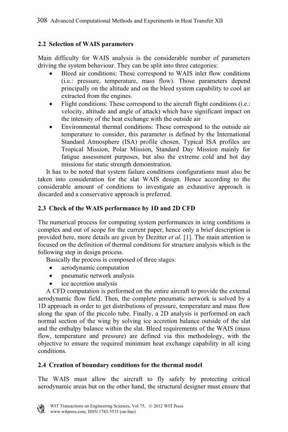
The CFD domain is limited to the internal cavities of the slat. In addition, to maintain the numerical domain to a manageable size, only a section of the slat is modelled, which is usually limited to a box around a rib in order to benefit from symmetry conditions inside each bay, see Figure 3.
Figure 3: CFD cell location in comparison to slat thermal model.
As the geometry of the slat is not totally symmetrical versus span, some corrections must be introduced in order to not generate artificial cross flows. Piccolo jet areas are critical for heat transfer balance but are complex to model due to the high velocity of the jets; hence the mesh is created with particular attention on impinged areas, as shown in Figure 4.
Advanced Computational Methods and Experiments in Heat Transfer XII 309
www.witpress.com, ISSN 1743-3533 (on-line) WIT Transactions on Engineering Sciences, Vol 75, © 201 WIT Press2

Figure 4: Comparison between typical meshes for cfd (left) and thermal model (right).
The CFD model does not compute the flow field within the piccolo tube. The internal heat transfer coefficient within the piccolo is specified and the piccolo surface temperature is then calculated during the simulation. Gas total pressure and temperature are imposed at the piccolo holes areas and static pressure is imposed at the vent holes. The external boundary condition for the top skin is directly extracted from aerodynamic computations. The back skin is treated depending upon slat configuration (deployed or retracted). When the slat is retracted, the wall is considered adiabatic above the high speed seal. The back skin surface below the seal is exposed to the hot waste air from the vents. For both configurations an average back skin heat transfer coefficient is estimated based on a surface average Nusselt correlation. An example of the htc. calculated for the upper skin is shown in Figure 5. The effect of the acceleration slots is clearly visible here, though no detailed values can be given to protect Airbus IP rights.
Figure 5: Internal htc. at Aft-Bay upper skin from CFD.
2.5 Transfer of CFD results to the thermal model
This section deals with the data exchange between the system analysis and the structure thermal analysis and some of the issues are discussed that are
310 Advanced Computational Methods and Experiments in Heat Transfer XII
www.witpress.com, ISSN 1743-3533 (on-line) WIT Transactions on Engineering Sciences, Vol 75, © 201 WIT Press2

encountered during the transfer of heat transfer coefficients and reference temperatures obtained by CFD code to the thermal mesh.
First, the results available from the CFD analysis cell are used as internal boundary condition and for the entire slat in the span wise direction. This is realized by copying the results obtained for the rib in the CFD cell rib shown in Figure 1 to all other ribs and extruding the results to the bay skins and spars to all other slat bay skins and spars.
Second, the element size between the CFD mesh and the thermal mesh is considerably different as the structure thermal mesh is much coarser; see Figure 4. As a consequence, local peaks in the heat transfer well represented in the CFD results might be averaged during mapping onto the structure thermal mesh.
Third, the structure thermal analysis is run transiently along a typical flight mission including WAIS activation but CFD results are run steady state and are therefore available only for a limited number of points in time during the flight mission.
During a standard flight mission, icing conditions are normally encountered during climb, descent and holding phases. The approach for the structure thermal model is to consider WAIS is activated as shown in Figure 6.
Figure 6: Altitude during flight and WAIS activation.
Normally, CFD results are provided for the following four to five points during the flight mission: For WAIS activation and de-activation during climb, for activation and de-activation during decent and in addition for the holding phase, when the aircraft is circling under icing conditions while waiting for the airport to give clearance for landing.
Advanced Computational Methods and Experiments in Heat Transfer XII 311
www.witpress.com, ISSN 1743-3533 (on-line) WIT Transactions on Engineering Sciences, Vol 75, © 201 WIT Press2
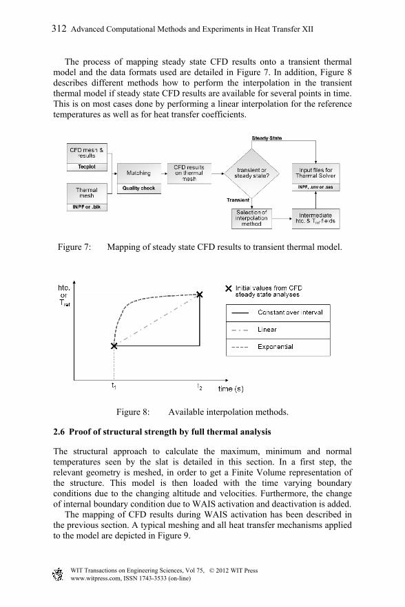
The process of mapping steady state CFD results onto a transient thermal model and the data formats used are detailed in Figure 7. In addition, Figure 8 describes different methods how to perform the interpolation in the transient thermal model if steady state CFD results are available for several points in time. This is on most cases done by performing a linear interpolation for the reference temperatures as well as for heat transfer coefficients.
Figure 7: Mapping of steady state CFD results to transient thermal model.
Figure 8: Available interpolation methods.
2.6 Proof of structural strength by full thermal analysis
The structural approach to calculate the maximum, minimum and normal temperatures seen by the slat is detailed in this section. In a first step, the relevant geometry is meshed, in order to get a Finite Volume representation of the structure. This model is then loaded with the time varying boundary conditions due to the changing altitude and velocities. Furthermore, the change of internal boundary condition due to WAIS activation and deactivation is added. The mapping of CFD results during WAIS activation has been described in the previous section. A typical meshing and all heat transfer mechanisms applied to the model are depicted in Figure 9.
312 Advanced Computational Methods and Experiments in Heat Transfer XII
www.witpress.com, ISSN 1743-3533 (on-line) WIT Transactions on Engineering Sciences, Vol 75, © 201 WIT Press2

Figure 9: Slat thermal model.
The thermal model is run transiently for a complete flight for different environmental conditions, e.g. for a Hot Day, a Cold day and a Standard Day mission. These missions always include the typical flight segments like ground soak, taxi, ground run, take off, climb, cruise, decent, approach, landing, taxi in and then again ground soak. An example of results obtained by transient structure thermal analysis is shown in Figure 10 as temperature evolution over the mission time.
Figure 10: Structure thermal analysis results.
The temperatures resulting from the full thermal model are then used for fatigue and ageing analysis of the structure as well as for static strength demonstration including thermal effects.
Advanced Computational Methods and Experiments in Heat Transfer XII 313
www.witpress.com, ISSN 1743-3533 (on-line) WIT Transactions on Engineering Sciences, Vol 75, © 201 WIT Press2
3 Conclusions and outlook
In order to prove system performance and structural integrity, both sides involved in the slat thermal analyses need to base their work on consistent numerical models all along the thermal analysis process and on consistent assumptions the WAIS usage and flight conditions.
3.1 Consistency of numerical models
The consistency of numerical models must be ensured for both the geometry and meshing. The current CFD approach is to analyse a box around a critical rib of the slat, but the slat external shape changes in span wise direction. As the CFD cell is located in the part of the slat where the maximum temperatures occur, slat temperatures will be slightly overestimated in other slat locations, when these boundary conditions are used along the entire slat length. Furthermore, the geometry in the region where the piccolo tube enters the slat is completely different leading to different jet orientations compared to the situation in the CFD cell used. For the consistency of meshes at present a manual check is performed after the mapping, in order to ensure that no local peaks are lost as this would lead to a local underprediction of structure temperature. If such an effect is observed, the thermal mesh is locally refined in order to avoid losing local heat transfer peaks present in the CFD results.
3.2 Consistency of WAIS aircraft conditions
The selection of the WAIS conditions to be taken into account and the down-selection of the relevant cases remains challenging as the current approach is highly conservative and consists in taking the maximum conditions from the WAIS perspective. A refined approach could be based on using a number of profiles of thermal missions in combination with bleed behaviour variations. This is seen to represent a good opportunity to reduce with limited additional effort the amount of conservatism. Further reduction of conservatism can be achieved by additionally taking into account other aircraft parameters when combining analysis cases. An example here is not to combine stress load cases during WAIS activation with maximum slat temperatures but with realistic temperature distributions for this flight segment corresponding to different WAIS cases. The reduction in conservatism is realized by increasing the number of analysis cases. Not the most conservative combination of all conditions is used cover the entire aircraft life, but several cases are used instead that in combination represent the thermal conditions the slat will see through its service life.
314 Advanced Computational Methods and Experiments in Heat Transfer XII
www.witpress.com, ISSN 1743-3533 (on-line) WIT Transactions on Engineering Sciences, Vol 75, © 201 WIT Press2
Abbreviations
The abbreviations used throughout this text and a brief explanation of their meaning are given in the following Table 1.
Table 1: Abbreviations used.
Abbreviation Meaning CFD Computational Fluid Dynamics FV Finite Volume HTC Heat Transfer Coefficient ISA International Standard Atmosphere WAIS Wing Anti Ice System
References
[1] F.Dezitter, G.Chene, S.Viala, B.Calmels, 3D Ice Accretion and Aerodynamic Penalties Prediction on Aircraft, AIAA 2003-383, 16th AIAA Computational Fluid Dynamics Conference, 23-26 June 2003, Orlando, Florida.
Advanced Computational Methods and Experiments in Heat Transfer XII 315
www.witpress.com, ISSN 1743-3533 (on-line) WIT Transactions on Engineering Sciences, Vol 75, © 201 WIT Press2