thermal-hydraulic analysis of an ahtl in-pile tube in the ... documents... · –the core power...
TRANSCRIPT

ww
w.in
l.g
ov
Thermal-Hydraulic Analysis of an AHTL In-Pile Tube in the Southwest Loop of the ATR
2015 IRUG Meeting
Idaho Falls, ID
August 13-14, 2015
C. B. Davis

2
Outline
• Background
• ATR description
• Code description
• Results
• Conclusions

3
Background
– The standard in-pile tube (IPT) in the Southwest loop of the Advanced Test Reactor (ATR) was replaced by a spare IPT designed for use in the ATR High-Temperature Loop (AHTL)
– The standard and AHTL IPTs are similar but have two differences that are potentially significant
• A thicker envelope tube
• A reduced diameter of the pressure tube near the bottom of the reactor
– These differences could affect the behavior of the loop during normal operation and during accidents
– Since the differences could affect accidents analyzed in the safety basis, they were evaluated using RELAP5

ATR Description Reactor Type
• Pressurized, light-water moderated and cooled; beryllium reflector
• 250 MWt (Full Power)
Reactor Core
• 40 fuel elements, curved-plate, aluminum-clad metallic U-235
• Highly enriched uranium matrix (UAlx) in an aluminum sandwich plate cladding
4
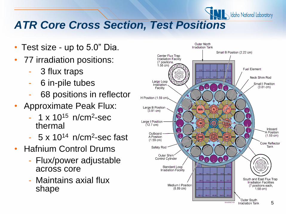
ATR Core Cross Section, Test Positions
• Test size - up to 5.0” Dia.
• 77 irradiation positions:
- 3 flux traps
- 6 in-pile tubes
- 68 positions in reflector
• Approximate Peak Flux:
- 1 x 10¹⁵ n/cm2-sec thermal
- 5 x 10¹⁴ n/cm2-sec fast
• Hafnium Control Drums
- Flux/power adjustable across core
- Maintains axial flux shape
5

6
IPT cross section
• The thicker (~15%) envelope tube in the AHTL IPT causes
additional gamma heating and a thinner helium annulus
• The thinner helium annulus causes more heat loss to the reactor
Loop water, flow
tube, and test
Pressure tube
Helium
Envelope tube
Reactor water
7
The inner diameter of the pressure tube near the bottom of the reactor was reduced by about 3% in the AHTL IPT
• The reduced diameter increased the hydraulic resistance of the IPT slightly, which had the potential to affect a flow coastdown in the loop
• The loss coefficients at one junction were increased by about 5% to account for the reduced inner diameter
• Although the design differences were not expected to have a large impact on calculated results, they were evaluated to verify that the effects were small

8
Code description
• Both RELAP5/MOD2.5 and RELAP5/MOD3 are used in the ATR safety basis
– RELAP5/MOD3 is used to determine the response of the experiment loops
– RELAP5/MOD2.5 is used to determine the response of the reactor
• RELAP5/MOD3 Version 3.2.1.2 was used to generate the results described in this analysis

9
The following cases were analyzed:
• Steady-state operation at full power
• Maximum allowable operating temperatures
• Reactivity insertion accident (RIA) initiated by a Condition 4 loop blowdown
• RIA initiated by a Condition 2 loop blowdown
• RIAs initiated by Condition 4 flow coastdowns in a single loop or all six experiment loops
• A Condition 4 seismic event that causes simultaneous loss-of-coolant accidents (LOCAs) in the experiment loops and the primary coolant system (PCS)
• Two RELAP5 calculations were performed for each case
– One with the standard IPT
– One with the AHTL IPT

10
Results for the maximum allowable operating temperature analysis
• Maximum allowable operating temperatures at the inlet and outlet of the IPT are determined to protect the IPT
– The average temperature of the pressure tube wall at the hottest location must be ≤800°F
– The maximum bulk fluid temperature in the IPT must be ≤ the saturation temperature
• Sixteen cases were evaluated for a range of operating pressures and flows
• The calculated results with the SIPT bounded the results obtained with the AHTL IPT
– At the IPT inlet, the maximum allowable temperature with the AHTL IPT was usually 2 to 4oF higher than with the SIPT
– The maximum pressure tube temperatures were always lower with the AHTL IPT

11
RIAs due to Condition 4 and Condition 2 loop blowdowns
• The Condition 4 blowdown was initiated by a double-ended break of the pump discharge line
• The Condition 2 blowdown was initiated by a double-ended break of the heater drain line manifold
• These cases were previously shown to be the worst loop blowdowns
• Sensitivity calculations described in the ATR safety basis were also performed for both transients
• The differences between the standard and AHTL IPTs caused only slight differences in the maximum core power and maximum energy deposition during the RIAs
– Sometimes the maximum values were slightly higher with the SIPT and sometimes they were slightly higher with the AHTL

12
RIA due to the Condition 4 loop blowdown (cont’d)
• The differences were small
compared to the margin
between the calculations and
the envelope curves established
in the Safety Analysis Report
(SAR)
• The calculated results are
within the SAR if they are
within the envelope curves

13
RIAs due to Condition 4 flow coastdowns in the experiment loop
• The SAR considers RIAs due to the flow coastdown of a single experiment loop and simultaneous flow coastdowns in all six experiment loops
• Both flow coastdown events were simulated with RELAP5
• The differences between the standard and AHTL IPTs caused only slight differences in the maximum core power and maximum energy deposition during the RIAs
– Sometimes the maximum values were slightly higher with the SIPT and sometimes they were slightly higher with the AHTL

14
RIA due to the Condition 4 simultaneous coastdown of all six experiment loops (cont’d)
• The differences were small
compared to the margin
between the calculations and
the SAR envelope curves
• The effect of the change in IPTs
is overstated because only the
SIPT in the SW loop will be
replaced by the AHTL IPT but
the calculations assume that all
of the IPTs are being replaced

15
Seismic event that causes simultaneous LOCAs in the experiment loops and the PCS
• The SAR considers a Condition 4 seismic event that causes simultaneous LOCAs in six experiment loops and the PCS
• The LOCA in each experiment loop was initiated by a double-ended break of the heater drain line manifold
• The LOCA in the PCS involved a 1-inch diameter reactor vessel inlet break, a 2.5-inch rupture of the bypass demineralizer inlet line, and 50 gpm of additional PCS leakage
• Analysis of this event was reported at the 2013 meeting*
_______
*D. Gerstner and C. Davis, Thermal-Hydraulic Analysis Results of a Seismically Induced Loss of Coolant Accident Involving Experiment Out-of-Pile Loop Piping at the Idaho National Engineering Laboratory Advanced Test Reactor, 2013 RELAP5 International Users Seminar, September 12-13, 2013, Idaho Falls, Idaho

16
Seismic event that causes simultaneous LOCAs in the experiment loops and the PCS (cont’d)
• The differences in the core power
due to the changes in the IPT were
small, but the calculated power
was about 3% higher with the
AHTL IPT near 25 s
• The minimum approach to thermal
margins occurs at about 25 s
• The effect of the change in IPTs is
overstated because only the SIPT
in the SW loop will be replaced by
the AHTL IPT
• The margin to the Condition 4
limits allowed in the SAR is
relatively large

17
Conclusions
• The maximum allowable operating temperatures obtained for the standard IPT bound the results obtained with the AHTL IPT
• The differences between the standard and AHTL IPTs cause only slight differences in the maximum core power and maximum energy deposition during the RIAs
– Sometimes the maximum values were slightly higher with the SIPT and sometimes they were slightly higher with the AHTL IPT
– The differences were small and judged to be negligible compared to the margin between the calculations and the SAR envelope curves
– Therefore, the operating limits established for the standard SIPT also apply to the AHTL IPT when operated at standard loop conditions

18
Conclusions (cont’d)
• The differences between the standard and AHTL IPTs also cause only slight differences in the calculated core power during a seismic event that cause simultaneous LOCAs in the experiment loops and the PCS
– The core power during the approach to minimum thermal margins was slightly higher with the AHTL IPT so the minimum thermal margin would be slightly lower
– Since the margin to the Condition 4 limits is relatively large for this accident, SAR conclusions about meeting plant protection criteria are not changed by replacing the standard IPT in the SW loop with the AHTL IPT