thermal fatigue damage of the divertor plate
TRANSCRIPT

Fusion Engineering and Design 49–50 (2000) 343–348
Thermal fatigue damage of the divertor plate
Satoshi Suzuki *, Koichiro Ezato, Kazuyoshi Sato, Kazuyuki Nakamura,Masato Akiba
NBI Heating Laboratory, Naka Fusion Research Establishment, Japan Atomic Energy Research Institute (JAERI),801-1 Mukoyama, Naka-machi, Naka-gun, Ibaraki-ken 311-01, Japan
Abstract
Thermal fatigue of the divertor plate is one of the key issues which governs the lifetime of the divertor plate. Athermal cycling experiment of divertor mock-ups was carried out to investigate the thermal fatigue behavior of thedivertor structure in a high heat flux test facility at Japan Atomic Energy Research Institute (JAERI). A cyclic heatflux of 5 MW/m2 was loaded onto the mock-ups to simulate the steady state thermal condition of ITER divertorplate. A pulse duration of 30 s was selected so that the mock-ups reach thermal steady state. The mock-ups showedwater leakage due to thermal fatigue cracking of the cooling tube after 400 cycles. The fatigue crack was observed atthe top of the cooling tube. According to a numerical analysis, the maximum strain amplitude was over 5% at thetop of the cooling tube. The cracking of the cooling tube was caused by the large strain concentration due tostructural discontinuity of the copper heat sink. It was found that the heat sink block should be separated into smallerblocks to reduce the strain concentration at the cooling tube. © 2000 Elsevier Science B.V. All rights reserved.
Keywords: Thermal fatigue; Divertor plate; Copper
www.elsevier.com/locate/fusengdes
1. Introduction
Plasma facing components of next generationfusion devices, such as international thermonu-clear experimental reactor (ITER), are subjectedto a high thermal/particle load and an electromag-netic load during operation. In particular, a diver-tor plate is requested to handle the highestthermal load among the plasma facing compo-nents in ITER. The thermal load is cyclicallyloaded to the divertor plate due to a repetitious
operation of ITER. Therefore, it is one of themost important issues for the divertor plate toinvestigate the thermal fatigue behavior againstcyclic thermal loads, since thermal fatigue of thestructural material strongly affects the integrity ofthe divertor plate.
So far, thermal cycling experiments have beencarried out in many institutions to investigate thethermal fatigue behavior of the divertor plates[1–3]. However, most of these experiments werefocused on the integrity of the bond interfacebetween the armor and the heat sink materials.The authors have reported the thermal fatigue onthe cooling tube made of oxygen-free-high-con-ductivity copper (OFHC-Cu) [4], which have
* Corresponding author. Tel.: +81-29-2707552; fax: +81-29-2707558.
E-mail address: [email protected] (S. Suzuki).
0920-3796/00/$ - see front matter © 2000 Elsevier Science B.V. All rights reserved.
PII: S0 920 -3796 (00 )00394 -X

S. Suzuki et al. / Fusion Engineering and Design 49–50 (2000) 343–348344
Fig. 1. Schematic drawing of particle beam engineering facility(PBEF).
Atomic Energy Research Institute (JAERI).PBEF can produce hydrogen ion beam at anacceleration voltage up to 50 kV and at a beamcurrent up to 30 A for 1000 s. One of the advan-tages of the usage of hydrogen ion beam as a heatsource is low reflectivity for a metal target. Inparticular, it is suitable to simultaneously heattarget surfaces, which are made of different kindsof materials, such as a combination of carbon andtungsten. The schematic drawing of PBEF isshown in Fig. 1. The dimension of vacuum cham-ber is 3.5 m (width)×4 m (height)×7 m (length).A large ion source has been developed and imple-mented to perform high heat flux experiments oflarge-scale mock-ups. The large ion source is ca-pable of producing sheet-like hydrogen ion beamsat an irradiation area of 10 cm×1 m with amaximum heat flux of 10 MW/m2.
2.2. Di6ertor mock-up
A divertor mock-up simulating an inboard ver-tical target was developed. Fig. 2 shows the sche-matic drawing of the divertor mock-up. Themajor dimension of the divertor mock-up is 35mm (width)×1.3 m (length), which correspondsto a single slice of the ITER inboard verticaltarget. The surface material of the mock-up ismade of powder-sintered tungsten and a unidirec-tional carbon-fiber-reinforced-carbon composite(1D-CFC). This surface material combination isbased on the ITER-FDR design [5]. These surfacematerials were directly brazed onto OFHC-Cuheat sink with a silver braze material (Ti–Cu–Ag). The braze process was conducted in a vac-uum environment at a temperature of 850°C for ahold time of several minutes. The cooling tube has
pointed out the low cycle fatigue fracture of theOFHC-Cu cooling tube under the ITER divertorthermal conditions. In this study, aluminum-ox-ide-dispersion-strengthened copper (DSCu) waschosen as the structural material of the coolingtube to improve the durability against a cyclicthermal stress. In addition, a full-scale ITER di-vertor mock-up (vertical target) was fabricated tosimulate the realistic mechanical condition of theITER divertor plate, such as mechanical con-straint from a rigid back plate and a stress con-centration due to geometrical discontinuity of thedivertor structure.
2. Experiment
2.1. Test facility
The test facility used in this study is particlebeam engineering facility (PBEF) in Japan
Fig. 2. Schematic drawing of ITER divertor (vertical target) mock-up.
S. Suzuki et al. / Fusion Engineering and Design 49–50 (2000) 343–348 345
Fig. 3. Surface temperature evolution of the mock-up (com-parison between the experimental data and the analyticaldata).
the steady state thermal condition of the ITERdivertor was conducted in PBEF. A heat flux of 5MW/m2 was cyclically loaded onto the surface ofthe armor tiles. The heating duration of 30 s andthe suspend duration of 120 s were selected sothat the mock-up reached the thermal steadystate. Since this experiment focuses on the thermalfatigue behavior of the structural material of thedivertor plate, the heating duration of 30 s waschosen to avoid suffering from creep damage. Inthe thermal fatigue experiment, an infrared cam-era monitored surface temperature profile; thetemperature evolution of the heat sink was moni-tored by thermocouples attached on the side. Thecoolant was purified water with an axial flowvelocity of 10 m/s at a temperature of 25°C.
2.4. Experimental results
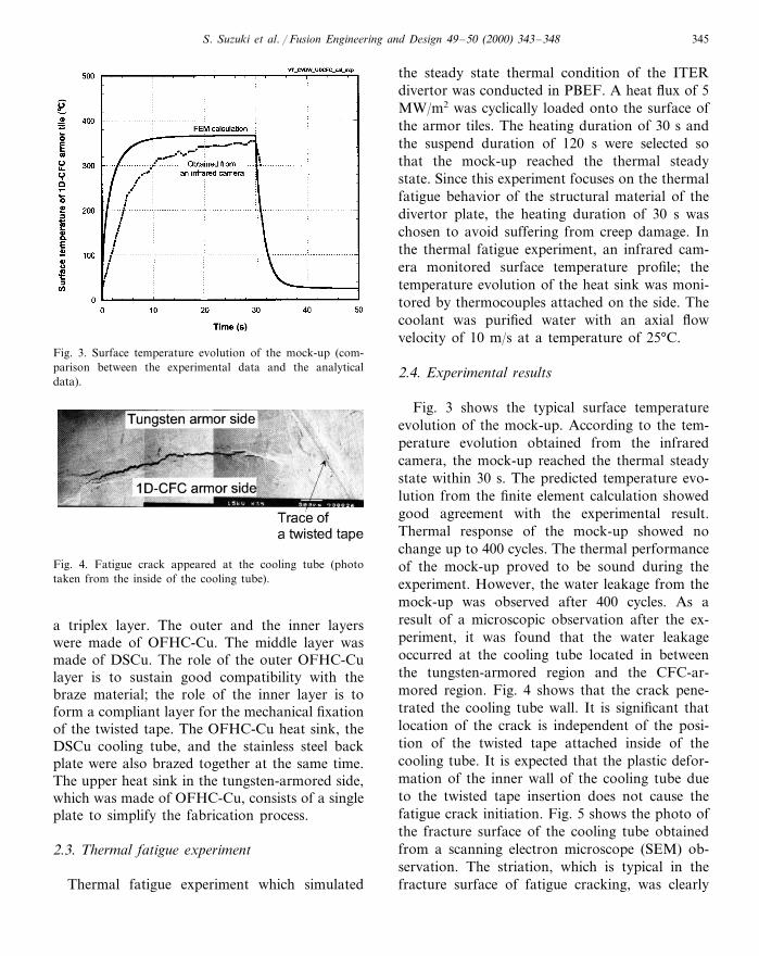
Fig. 3 shows the typical surface temperatureevolution of the mock-up. According to the tem-perature evolution obtained from the infraredcamera, the mock-up reached the thermal steadystate within 30 s. The predicted temperature evo-lution from the finite element calculation showedgood agreement with the experimental result.Thermal response of the mock-up showed nochange up to 400 cycles. The thermal performanceof the mock-up proved to be sound during theexperiment. However, the water leakage from themock-up was observed after 400 cycles. As aresult of a microscopic observation after the ex-periment, it was found that the water leakageoccurred at the cooling tube located in betweenthe tungsten-armored region and the CFC-ar-mored region. Fig. 4 shows that the crack pene-trated the cooling tube wall. It is significant thatlocation of the crack is independent of the posi-tion of the twisted tape attached inside of thecooling tube. It is expected that the plastic defor-mation of the inner wall of the cooling tube dueto the twisted tape insertion does not cause thefatigue crack initiation. Fig. 5 shows the photo ofthe fracture surface of the cooling tube obtainedfrom a scanning electron microscope (SEM) ob-servation. The striation, which is typical in thefracture surface of fatigue cracking, was clearly
Fig. 4. Fatigue crack appeared at the cooling tube (phototaken from the inside of the cooling tube).
a triplex layer. The outer and the inner layerswere made of OFHC-Cu. The middle layer wasmade of DSCu. The role of the outer OFHC-Culayer is to sustain good compatibility with thebraze material; the role of the inner layer is toform a compliant layer for the mechanical fixationof the twisted tape. The OFHC-Cu heat sink, theDSCu cooling tube, and the stainless steel backplate were also brazed together at the same time.The upper heat sink in the tungsten-armored side,which was made of OFHC-Cu, consists of a singleplate to simplify the fabrication process.
2.3. Thermal fatigue experiment
Thermal fatigue experiment which simulated

S. Suzuki et al. / Fusion Engineering and Design 49–50 (2000) 343–348346
observed in the outer and the inner OFHC-Culayer of the cooling tube. On the other hand, noclear evidence of fatigue cracking was found inthe middle layer made of DSCu. As shown in Fig.6, the fracture surface of the middle layer is quitedifferent from that obtained from the OFHC-Culayer. This fracture surface implies brittle fracturethat occurred in the DSCu layer. Therefore, thenumber of thermal cycles required so that thefatigue crack penetrates the DSCu layer is ex-pected to be very small. Therefore, the experimen-tal result in this study suggests that the fatiguelifetime of DSCu is not dominated by the num-ber of crack growth but mainly by the number
of cycles for fatigue crack initiation. It is alsosupposed that DSCu is a crack-sensitive materialand has high crack growth rate after crack initia-tion.
3. Discussion
A thermal fatigue cracking of the copper-basedcooling tube at this heat flux level (5 MW/m2) hasnever been observed in the high heat flux experi-ments formerly performed at JAERI [6]. In addi-tion, the fact that the fatigue crack appeared atthe cooling tube in between the tungsten-armoredregion and the CFC-armored region implies aspecific reason of this fatigue damage. It is ex-pected that the cyclic thermal deformation of theupper heat sink and the constraint due to the rigidback plate caused large strain concentration at thecooling tube.
Three-dimensional finite element analyses wereperformed to clarify the reason of this fatiguefracture. The finite element code used wasABAQUS, version 5.7 [7]. Fig. 7 shows a finiteelement model and the boundary conditions ofthe analyses. The model includes six armor tileswith three tungsten tiles and three 1D-CFC tiles,which corresponds to the central part of themock-up. Eight node-linear elements were used inthe thermal and stress analyses. In the thermalanalysis, uniform heat flux of 5 MW/m2 onto thesurface of all armor tiles was assumed to simulatethe experiment. Based on the temperature evolu-tion obtained in this transient thermal analysis,subsequent elastoplastic stress analyses were per-formed. Prior to the elastoplastic stress analysisassuming the cyclic thermal loading, a residualstress analysis was conducted to obtain the initialstress field of the model. The residual stress be-haved as mean stress during the cyclic thermalloading. The reference temperature of the residualstress analysis was 780°C, which corresponded tothe solidified temperature of the Ti–Cu–Ag brazematerial. In the stress analysis, elastoplastic be-havior of DSCu and OFHC-Cu was taken intoaccount; the material properties of OFHC-Cuwere assumed to be of a fully annealed material.Fig. 8 shows the equivalent mechanical strain
Fig. 5. Fracture surface of the cooling tube (photo taken fromthe inner OFHC-Cu layer).
Fig. 6. Fracture surface of the cooling tube (photo taken fromthe middle DSCu layer).

S. Suzuki et al. / Fusion Engineering and Design 49–50 (2000) 343–348 347
Fig. 7. Finite element mesh and boundary condition (line ‘A’ corresponds to the top of the outer surface of the tube).
profile along the line ‘A’ corresponding to thetop of the outer surface of the cooling tube.Large strain concentration appeared at the topof the tube locating in between the armor tiles.Particularly, the largest equivalent mechanicalstrain of 6.6% was obtained at the tube adjoin-ing the tungsten-armored side and the CFC-ar-mored side. The result of the residual stressanalysis shows that the stress field of theOFHC-Cu layer is in an elastoplastic state afterthe braze process. Subsequently, the elastoplasticstress analysis simulating the experiment wascarried out using this residual stress field as aninitial condition. In the analysis, three thermalcycles were assumed to stabilize the stress–strainbehavior of the model. Fig. 8 also shows theequivalent mechanical strain amplitude of thecooling tube obtained at the third thermal cycle.The maximum equivalent mechanical strain am-plitude of 5.2% appeared at the tube adjoiningthe tungsten-armored side and the CFC-armoredside. As a result of these stress analyses, it wasfound that the low cycle fatigue fracture wascaused by the large strain concentration and bythe large strain amplitude of the cooling tube.Moreover, the geometric discontinuity formedby the upper heat sink, which consists of a sin-gle OFHC-Cu plate, caused the strain concen-tration because the peak of the strain profile atthe CFC-armored side along the line ‘A’ was
not as significant as that of the crack region. Toavoid such fatigue cracking, separation of theupper heat sink is essential for this divertorstructure.
Fig. 8. Strain distribution along line ‘A’ after braze processand mechanical strain amplitude at the end of the third cycle.

S. Suzuki et al. / Fusion Engineering and Design 49–50 (2000) 343–348348
4. Conclusion
Based on this study, we draw the followingconclusions:1. Thermal fatigue experiment of the ITER di-
vertor (vertical target) mock-up was per-formed in PBEF. The DSCu cooling tube withtriplex layer showed low cycle fatigue fractureat 400 thermal cycles under a cyclic heat fluxof 5 MW/m2.
2. The fatigue crack was found at the coolingtube adjoining the tungsten-armored side andthe CFC-armored side. According to the post-test microscopic observation, the DSCu layershowed a brittle fracture surface whereas theOFHC-Cu layer of the tube showed a clearevidence of the fatigue fracture. Since DSCuwas proved to be a crack-sensitive material inthis study, precise evaluation on the fatiguecrack initiation/growth is necessary to useDSCu as a cooling tube material for the diver-tor application.
3. It was found that the geometric discontinuityformed by the single plate heat sink stronglyaffects the fatigue lifetime of the cooling tube.For the design of the divertor plate, separationof the heat sink for each armor tile is essentialto avoid the large strain concentration at thecooling tube.
Acknowledgements
The authors wish to thank Y. Okumura andother members of NBI heating laboratory fortheir valuable discussions and comments. Theywould also like to acknowledge M. Ohta and S.Matsuda for their support and encouragement.
References
[1] G. Vieider, V. Barabash, et al., Overview of the EU smallscale mock-up tests for ITER high heat flux components,Fusion Eng. Des. 39–40 (1998) 211–218.
[2] M. Akiba, S. Suzuki, Overview of the Japanese mock-uptests for ITER high eat flux components, Fusion Eng. Des.39–40 (1998) 219–225.
[3] I. Mazul, R. Giniatulin, et al., Manufacturing and testingof ITER divertor gas box liners, Proceedings of the 20thSymposium on Fusion Technology, vol. A, 1998, pp. 77–80.
[4] S. Suzuki, T. Suzuki, et al., Development of divertor platewith CFCs bonded onto DSCu cooling tube for fusionreactor application, J. Nucl. Mater. 258–263 (1998) 318–322.
[5] ITER-EDA, Technical basis for the ITER Final DesignReport, cost review and safety analysis, ITER EDA docu-mentation series No. 16, 1998.
[6] S. Suzuki, T. Suzuki, Development of divertor high heat fluxcomponents at JAERI, Proceedings of the 17th IEEE/NPSSSymposium on Fusion Engineering, vol. 1, 1977, pp. 385–388.
[7] ABAQUS/Standard user’s manual version 5.7, Hibbitt,Karlsson & Sorensen, 1999.