thermal cracking performance prediction and asset ... 2... · thermal cracking performance...
TRANSCRIPT
USDOT Region V Regional University Transportation Center Final Report
IL IN
WI
MN
MI
OH
NEXTRANS Project No. 041IY02
Thermal Cracking Performance Prediction and Asset Management Integration
By
William G. Buttlar, Professor Associate Dean, Graduate College
Department of Civil and Environmental Engineering University of Illinois at Urbana-Champaign
Glaucio H. Paulino, Professor Donald Biggar Willett Professor of Engineering
Department of Civil and Environmental Engineering University of Illinois at Urbana-Champaign
Eshan Dave, Assistant Professor Department of Civil Engineering University of Minnesota-Duluth
and
Sofie Leon, Graduate Research Assistant Department of Civil and Environmental Engineering
University of Illinois at Urbana-Champaign

DISCLAIMER
Funding for this research was provided by the NEXTRANS Center, Purdue University under Grant No. DTRT07-G-005 of the U.S. Department of Transportation, Research and Innovative Technology Administration (RITA), University Transportation Centers Program. The contents of this report reflect the views of the authors, who are responsible for the facts and the accuracy of the information presented herein. This document is disseminated under the sponsorship of the Department of Transportation, University Transportation Centers Program, in the interest of information exchange. The U.S. Government assumes no liability for the contents or use thereof.

USDOT Region V Regional University Transportation Center Final Report
TECHNICAL SUMMARY
NEXTRANS Project No. 041IY02 Technical Summary - Page 1
IL IN
WI
MN
MI
OH
NEXTRANS Project No. 041IY02 Final Report, March 2011
Thermal Cracking Performance Prediction and Asset Management Integration
Introduction With shrinking maintenance budgets and the need to ‘do more with less,’ accurate, robust asset management tools are greatly needed for the transportation engineering community. In addition, the increased use of recycled materials and low energy production techniques such as warm-mix asphalt are leading to increased needs for preventive and rehabilitative maintenance activities. The timing of such activities will greatly affect the total discounted life-cycle cost of the pavement system. Low-temperature cracking of hot-mix asphalt (HMA) pavements continues to be a leading cause of premature pavement deterioration in regions of cold climate and/or where significant thermal cycling occurs. Recent advances in fracture testing and modeling of hot-mix asphalt (HMA) materials have greatly aided in the understanding of the key mechanisms behind this important pavement distress, which can greatly reduce pavement lifespan and the lifespan of subsequent rehabilitation cycles. However, there is a need for implementation of new models into a standalone program which can be readily utilized by researchers and practitioners. Moreover, the complete integration of material selection, material design, pavement design and pavement performance into a more holistic asset management system has been hampered by the lack of accurate, user-friendly performance prediction models for pavements.
The objective of this project was to complete the development of a user-friendly interface that provides simplified access to sophisticated low-temperature cracking prediction models. This stand-alone program will greatly accelerate the transfer of this technology to practitioners and other interested scientists and engineers (pavement designers, analysts, and researchers). The program is designed to be compatible with the existing thermal cracking model used in the Mechanistic Empirical Pavement Design Guide (MEPDG), and with the new thermal cracking model being developed under the National Pooled Fund Study on Low Temperature Cracking. As part of this report, the key developments associated with the new mechanics-based thermal cracking model are presented. The funding provided by this NexTrans supplement allowed the

NEXTRANS Project No. 041IY02 Technical Summary - Page 2
development of the thermal cracking software to include aspects which will facilitate its seamless integration into an overarching pavement management software program.
Findings A stand-alone low temperature cracking analysis program developed under this project and the National Pooled Fund Study on Low Temperature Cracking is presented in this report. Details on various components of the analysis modules were presented, including: mesh generation, viscoelastic pavement response calculation and finite element implementation of the numerical time-integration scheme, and pavement distress (thermal cracking) simulation via cohesive zone finite element modeling. The theoretical background for the finite element analysis program are also briefly presented in Chapter 2. The major components of this model were found to match reference solutions in the verification studies conducted. In order to make this comprehensive simulation model accessible to practitioners and other researchers, a user-friendly graphical user interface was developed, called ‘Visual LTC.’ Visual LTC, presented in Chapter 3, was written with the object-oriented programming language C# under Microsoft’s .NET framework. The key programming steps required to produce Visual LTC were also documented in this report. Finally, Chapter 4 presents a recently developed framework for the integration of mechanics-based pavement distress prediction into a comprehensive asset management system, which will be continued in the upcoming phase III research activities of this project.
Recommendations The next step in this research will involve the integration of the mechanics-based pavement distress prediction into a comprehensive asset management system. The first step will be to develop an integrated framework that links the new TCMODEL program with actual pavement cracking, distress and roughness, and to develop a framework that links the pavement roughness and distress information with vehicle maintenance and driver comfort. The proposed framework will also undertake the goal of extending fundamental predictions of pavement cracking distress to the prediction of pavement roughness and other forms of deterioration (crack spalling, potholes) as a function of pavement maintenance, traffic, and climate. This will lead to the development of an integrated model linking infrastructure condition to vehicle wear-and-tear and to driver safety.
Contacts For more information:
NEXTRANS Center Purdue University - Discovery Park

NEXTRANS Project No. 041IY02 Technical Summary - Page 3
3000 Kent Avenue West Lafayette, IN 47906 [email protected] (765) 496-9729 (765) 807-3123 Fax www.purdue.edu/dp/nextrans

i
ACKNOWLEDGMENTS
The authors acknowledge the assistance and feedback from the members of the
study advisory committee.
ii
TABLE OF CONTENTS
Page
LIST OF FIGURES ........................................................................................................... iv
CHAPTER 1. INTRODUCTION ....................................................................................... 1
1.1 Background and Motivation ................................................................................1
1.2 Relation to NexTrans Objectives .........................................................................2
1.3 Objectives ............................................................................................................2
1.4 Organization of this Report .................................................................................3
CHAPTER 2. LOW TEMPERATURE CRACKING MODEL FOR ASPHALT
PAVEMENTS ..................................................................................................................... 4
2.1 Introduction ..........................................................................................................4
2.2 Input File Generator .............................................................................................7
2.3 Finite Element Analysis Engine ........................................................................10
2.3.1 Viscoelastic Finite Element Analysis ....................................................... 10
2.3.2 Fracture Modeling of Asphalt Concrete ................................................... 14
2.4 Summary ............................................................................................................17
CHAPTER 3. VISUAL LTC: A GRAPHICAL USER INTERFACE FOR LOW-
TEMPERATURE CRACKING ANALYSIS ................................................................... 18
3.1 Introduction ........................................................................................................18
3.2 Development of Visual LTC .............................................................................18
3.2.1 Data storage .............................................................................................. 20

iii
3.2.2 Analysis modules ...................................................................................... 20
3.2.3 Results ....................................................................................................... 20
3.3 Use of Visual LTC .............................................................................................21
3.4 Future work and improvements to Visual LTC .................................................23
CHAPTER 4. DEVELOPMENT OF FRAMEWORK FOR ASSET MANAGEMENT
INTEGRATION ............................................................................................................... 24
4.1 Introduction ........................................................................................................24
4.2 Background ........................................................................................................24
4.3 Proposed Integration Framework ......................................................................26
CHAPTER 5. SUMMARY ............................................................................................... 31
REFERENCES ................................................................................................................. 33

iv
LIST OF FIGURES
Figure Page
Figure 2.1. Flowchart of stand-alone low temperature cracking model. ............................ 6Figure 2.2. Finite element model from input file generator ................................................ 8Figure 2.3. Material properties required by the analysis model ......................................... 9Figure 2.4. Comparisons for thermo-viscoelastic analysis conducted using recursive-incremental viscoelastic finite element formulations and commercial software ABAQUS (from Dave et al., 2010) .................................................................................................... 14Figure 2.5. Bi-linear cohesive zone model ....................................................................... 16Figure 2.6. Finite element (FE) engine results of the cohesive zone model with recursive incremental viscoelastic finite element formulations. Temperature linearly decreases from 0ºC to -10ºC during 600 sec. ............................................................................................. 16Figure 3.1. Key programming steps of Visual LTC ......................................................... 19Figure 3.2. Project information ......................................................................................... 21Figure 3.3. Step three of three to add an asphalt layer to the pavement structure ............ 22Figure 4.1. Project Outline and Major Research Steps ..................................................... 28Figure 4.2. Development of Probabilistic Model for Distress Prediction ......................... 30

1
CHAPTER 1. INTRODUCTION
1.1
With shrinking maintenance budgets and the need to ‘do more with less,’ the need
for accurate, robust asset management tools are greatly needed for the transportation
engineering community. Furthermore, increases in traffic intensity, vehicular loads, and
truck tire stiffness are placing additional ‘pressure’ on pavements across the United
States. Finally, modern practices in crude petroleum refining, such as ‘coking’, are
squeezing more high energy products out of each barrel of crude, and the increased use of
recycled materials and low energy production techniques such as warm-mix asphalt are
leading to increased needs for preventive and rehabilitative maintenance activities. The
timing of such activities will greatly affect the total discounted life-cycle cost of the
pavement system.
Background and Motivation
Low-temperature cracking of hot-mix asphalt (HMA) pavements continues to be a
leading cause of premature pavement deterioration in regions of cold climate and/or
where significant thermal cycling occurs. Recent advances in fracture testing and
modeling of hot-mix asphalt (HMA) materials have greatly aided in the understanding of
the key mechanisms behind this important pavement distress, which can greatly reduce
pavement lifespan and the lifespan of subsequent rehabilitation cycles. While new tests
and models represent powerful tools for the design of more reliable, more sustainable
flexible pavement systems, there is a need for implementation of the models into a
standalone program which can be readily utilized by researchers and practitioners.
Moreover, the complete integration of material selection, material design, pavement
design and pavement performance into a more holistic asset management system has
been hampered by the lack of accurate, user-friendly performance prediction models for

2
pavements. This research provides two of the critical links needed to move this
integrated approach to the state of practice (development of mechanics-based thermal
cracking model and development of user-friendly graphical-user interface), and presents
a framework for the next phase of research needed in the development of this
comprehensive, mechanics- and performance-based asset management model.
1.2
The scope of this work is within the vehicle-infrastructure research pillar of the
NexTrans center. This research is geared towards development of an integrated solution
scheme that incorporates short-term and long-term pavement performance solutions
through advanced research. The overall objective is to deliver a stand-alone user-friendly
tool to highway designers for design of thermal cracking resistant asphalt pavements.
This tool will greatly facilitate the design of economical pavement systems and the
utilization of modern material formulations and construction techniques that are
environmentally friendly and sustainable, such as the use of very high amounts of
recycled materials and the use of low energy/low emission warm mix technologies. In
addition, mechanics- and performance-based asset management model framework can be
readily extended to include other critical pavement distress types, such as rutting, fatigue
cracking, reflective cracking, and moisture damage.
Relation to NexTrans Objectives
1.3
The objective of this work was to complete the development of a user-friendly interface
that provides simplified access to sophisticated low-temperature cracking prediction
models. This stand-alone program will greatly accelerate the transfer of this technology
to practitioners and other interested scientists and engineers (pavement designers,
analysts, and researchers). The program is designed to be compatible with the existing
thermal cracking model used in the Mechanistic Empirical Pavement Design Guide
(MEPDG), and with the new thermal cracking model being developed under the National
Pooled Fund Study on Low Temperature Cracking. As part of this report, the key
Objectives

3
developments associated with the new mechanics-based thermal cracking model are
presented. The funding provided by this NexTrans supplement allowed the development
of the thermal cracking software to include aspects which will facilitate its seamless
integration into an overarching pavement management software program.
1.4
The remainder of this report is organized as follows:
Organization of this Report
• Chapter 2: Low Temperature Cracking Model for Asphalt Pavements – This
chapter summarizes the key elements of the new, mechanics-based thermal
cracking model, including the automated mesh generator, viscoelastic pavement
response model, and cohesive zone fracture model.
• Chapter 3: Visual LTC: A Graphical User Interface for Low-Temperature
Cracking Analysis – This chapter provides an in-depth summary of the newly
developed GUI for the mechanics-based thermal cracking model, along with
illustrative examples to provide a sense of the GUI’s ‘look and feel’
• Chapter 4: Development of Framework for Asset Management Integration – This
chapter presents the results of a series of collaborative meetings between
pavements and systems faculty at the University of Illinois, leading to the
development of a framework for the integration of the newly developed thermal
cracking software into a comprehensive asset management system. In addition,
details pertaining to the next proposed phase of research are presented, which will
focus on the extension of the thermal cracking amount prediction to include
severity and its effect on pavement roughness, vehicle wear and tear, and safety.
• Chapter 5: Summary – A summary of the completed research in Phase II and
upcoming research tasks in Phase III are presented.

4
CHAPTER 2. LOW TEMPERATURE CRACKING MODEL FOR ASPHALT PAVEMENTS
This chapter introduces a new stand-alone low temperature cracking analysis
program developed around a cohesive zone fracture model. Section 2.1 introduces the
analysis program along with the major components as well as the overall flow of
information and data. Section 2.2 describes the input file generator for the finite element
analysis code. Section 2.3 discusses the details on the formulation of viscoelastic and
cohesive zone finite elements. Section 2.4 summarizes the low temperature cracking
model.
2.1
In order to tackle thermal cracking distress from a design perspective, the most
widely accepted pavement design guide in United States, the AASHTO Mechanistic
Empirical Pavement Design Guide (MEPDG), utilizes a one-dimensional viscoelastic
analysis program with a Paris law cracking criteria based on linear elastic fracture
mechanics (LEFM). The aforementioned thermal cracking analysis program (commonly
referred to as, TCModel) was developed in early 1990’s (Lytton et al, 1993) and relies on
use of material tensile strength as the key input for linking the material behavior with
low-temperature cracking performance (Roque et al, 1995a, 1995b) using Linear-elastic
Fracture Mechanics (LEFM). A number of studies in recent years have demonstrated that
fracture in asphalt concrete is a highly non-linear phenomenon, typically characterized as
quasi-brittle behavior. This has been demonstrated through modeling (Song et al. 2006),
and through laboratory experiments (Wagoner et al. 2005; Li et al. 2006) amongst others.
TCModel does not capture these type of material failure behaviors. Furthermore, the
Introduction

5
crack propagation model in TCModel is based on Paris law (Paris et al., 1961), which is a
phenomenological model for linking structural response to pavement failure.
An accurate model is necessary to design asphalt concrete pavements that are
resistant to thermal cracking. The model must represent the time and temperature
dependent viscoelastic material behavior and capture the nonlinear fracture behavior of
quasi-brittle materials. Cohesive zone fracture models allow for accurate and efficient
representation of the quasi-brittle fracture in asphalt concrete (Song et al. 2006), while a
viscoelastic finite element analysis procedure, such as recursive-incremental scheme (Yi
and Hilton 1994; Zocher et al. 1997; Dave et al. 2010) captures the rate- and temperature-
dependent material behavior. Thus, a cohesive zone fracture model with a viscoelastic
finite element analysis engine is a suitable analysis procedure for thermal cracking
simulation in asphalt pavements. This type of procedure has been successfully utilized to
model thermal cracking in various pavement test sections (Marasteanu et al. 2007; Dave
et al. 2008). Previous studies have utilized commercial finite element software with user-
defined cohesive zone fracture models viscoelastic material models. However, use of
commercial software is a major hindrance in wide-spread deployment of such analysis
procedures to public and private agencies.
The present study dealt with development of a stand-alone analysis and design
software to predict thermal cracking performance of asphalt concrete pavements. The
software program provides an intuitive and user-friendly graphical user interface (GUI)
as a means to perform rigorous viscoelastic finite element analysis with cohesive zone
modeling. The program can be divided into GUI and analysis modules. The GUI collects
and compiles the input conditions provided by the user and executes various analysis
modules to conduct finite element analysis as well as interpret the results. In-depth
description of GUI along with details on its implementation is presented in the next
chapter. The analysis modules are briefly described in this chapter.
The overall flow of program along with various inputs and outputs is graphically
illustrated in Figure 2.1. As seen from the figure, the code consists of three major analysis
modules, namely, the integrated climatic model, the input file generator and the finite

6
element analysis engine. The integrated climatic model (ICM) used in the analysis
program is same as that available in the AASHTO MEPDG. The ICM modulus from
MEPDG is being presently utilized to generate the pavement temperature profiles. In the
next phase of the project, a series of ICM simulations will be conducted to have a library
of pavement temperature profiles available to the user. At last three sets of temperature
profiles will be generated for each State participating in the Pooled Fund Study (sister
project to this NexTrans project) for various pavement configurations. The Input File
Generator module generates all necessary files for the finite element analysis engine.
Finally, the Finite Element module is executed, it simulates the pavement for evaluation
of thermal cracking potential. The results are read by the GUI and interpreted into user-
friendly plots and tables. Subsequent sections provide descriptions of Input File
Generator and Finite Element Analysis modules.
Figure 2.1. Flowchart of stand-alone low temperature cracking model.

7
2.2
The first task of the Input File Generator is to develop a finite element mesh for
the pavement geometry selected by user. The finite element mesh consists of coordinates
of the nodal points, and an element connectivity table that links node numbers to their
respective elements. During the first phase of low temperature pooled fund study
preliminary version of mesh generator was developed (Marasteanu et al., 2007). In the
present work, this mesh generation code was significantly revised and extended to
develop full pavement models, perform checks for inconsistencies in the mesh, and
automatically insert interfacial cohesive elements. Based on the recommendations and
findings from previous studies (Paulino et al. 2006; Dave et al. 2007), the finite element
domain size 6 m is selected. The mesh generation code creates smaller elements near the
potential crack path and gradually transitions them to larger size to reduce the
computational costs. The finite elements near the potential crack path are generated with
4 mm edge lengths, this is also based on the recommendations from previous studies
(Paulino et al. 2006; Dave et al. 2007). The code generates a finite element mesh using
four node quadrilateral elements (Q4) and it automatically increases the element side
lengths in the longitudinal direction of pavement (x-direction) until the relative difference
be the element side lengths reach 30%. At this point the mesh generator combines the
smaller elements into one larger element using a three-to-one transition scheme.
Input File Generator
Figure 2.2 shows a typical pavement mesh with four asphalt concrete layers,
including the three-to-one transition, generated using the software. The code supports
multiple lifts of asphalt concrete, each with distinct material properties and thicknesses.
To insert cohesive interface elements, the code traverses the mesh and generates
duplicate nodes along the potential crack path. Next, cohesive zone elements are inserted
and attached to the duplicate nodes. The location of cohesive elements is also illustrated
in Figure 2.2.

8
(a) Model geometry and boundary conditions (domain size: 0.18 m by 6 m, four asphalt
layers)
(b) Close-up of the mesh in vicinity of potential crack path.
Figure 2.2. Finite element model from input file generator
The second task of the Input File Generator is to create the material data file,
which is primarily based on the information provided by the user. This file consists of
viscoelastic (bulk) properties, the thermal expansion and contraction coefficient, and
fracture properties. The list of properties utilized by the analysis code is shown in Figure
2.3.
x
y Three-to-one transition
Cohesive zone elements Layer-1
Layer-2
Layer-3
Layer-4
Direction of Traffic
Asphalt Concrete Layers
6 meter
Potential crack path (Cohesive zone elements)
Region shown in Figure 2.2(b)

9
Figure 2.3. Material properties required by the analysis model
The user can either directly input the coefficient of thermal expansion and
contraction (CTEC) or provide asphalt mixture volumetric properties. If volumetric
properties are provided, the CTEC is estimated using the approximation equation utilized
by the AASHTO MEPDG software.
In the present version of software, the user is required to provide the thermo-
viscoelastic material properties in form of Prony series parameters (Generalized Maxwell
model) and time temperature shift factors. The viscoelastic model coefficients can be
determined by using creep testing of asphalt concrete following the AASHTO T-322 test
procedure. In the next phase of this project, modifications will be made such that users
can directly enter laboratory measured 1000 second creep test data from three
temperatures. Tensile strength can also be determined using the AASHTO T-322 test
procedure.
The fracture energy of asphalt concrete can be determined using a variety of test
geometries, such as disk-shaped compact tension (DC[T]), semi-circular bend (SC[B])
and single-edge notched beam (SEN[B]) test. Currently, the model is anticipated to be
calibrated and validated for the fracture energy obtained from the ASTM D7313 test
procedure that utilizes DC[T] test geometry. Furthermore, the test is expected to be
performed at crack mouth opening displacement (CMOD) rate of 0.0167 mm/s and at
temperature of 10°C above the 98% reliability Superpave PG low temperature grade, as
dictated by the project location.
Finally, the Input File Generator also provides the analysis engine with
temperature loading conditions. The finite element framework requires that temperature
conditions be applied at each node. Input generator uses the ICM output to generate nodal
Material Properties Required for Analysis Engine 1. Parameters for generalized Maxwell model (spring and dashpot coefficients) and
reference temperature 2. Time-temperature shift factors for two temperatures other than reference temperature 3. Coefficient of thermal expansion and contraction 4. Fracture energy 5. Tensile strength

10
temperatures at the necessary locations and times, which are then passed to the finite
element analysis engine.
2.3
Finite element analysis is becoming increasingly popular in the design and
analysis of pavements, for example, the current AASHTO design guide (MEPDG)
utilizes finite element analysis for determination of critical pavement responses. The
ability to model complex geometries and boundary conditions make finite element
analysis well-suited for simulation of asphalt pavements. Material behavior of asphalt
concrete is time and temperature dependent with hereditary response requiring the use of
thermo-viscoelastic analysis.
Finite Element Analysis Engine
In order to simulate the complex mechanisms underlying the thermal cracking
phenomenon, a standard “strength of materials” type analysis is insufficient, due to: 1)
the highly non-linear behavior in the vicinity of the crack tip, and 2) the importance of
the crack in the overall structural response (i.e., the need to model thermal crack as a
moving boundary value problem). The cohesive zone model provides a computationally
efficient way to predict the damage occurring in a process zone located ahead of a crack
tip in a material. In the present project a finite-element analysis program is being created
that utilizes both, (1) bulk viscoelastic behavior and, (2) cohesive zone model.
Description and formulations for each of these components are described in subsequent
sub-sections.
2.3.1 Viscoelastic Finite Element Analysis General viscoelastic theory can be found in several textbooks and articles, for
example, Christensen (1982). A generalized Maxwell model is utilized in this study due
to its flexibility in representing a wide variety of viscoelastic materials as well as the
availability of established formulations in the literature. The constitutive relationship for
generalized Maxwell model can be given as,

11
( ) ( ) ( ) ( )'' ''
0
t dd
d
ξξ ξ ξ ξ ξ
ξ∞= + −∫ t
εσ E ε E (1)
where σ is stress, ε is strain, ξ is reduced time and ∞E is fully relaxed modulus and tE
is relaxation modulus for the Maxwell chains. The relaxation modulus for Maxwell units
is given by,
( )' /
1
;mM
mt m m
mm
e ξ ξ− −
=
= =∑ τ ηE EτE
(2)
The material parameters ,m mEη are spring coefficients and viscosities for the thm
Maxwell unit. The spring coefficients and viscosities are related through relaxation times
mτ and the total number of Maxwell units in the model is given by M . The effect of
temperature on the material properties is accounted for through use of time-temperature
superposition principle. The superposition is governed time-temperature shift factor Ta
which is a material property. The real time t is related to the reduced time ξ and
temperature T as,
( )
'
'0 ,
t
T
dta T t
ξ = ∫ (3)
For isotropic conditions the above shown constitutive relationships can be re-
written in form of deviatoric and volumetric stress-strain relationships as,
( ) ( ) ( ) ( )
( ) ( ) ( )
'' '
'0
' ''
0
3 3
2 2
kkkk kk t
sijs
ij ij t
dK K d
d
ds G G d
d
ξ
ξ
ε ξσ ξ ε ξ ξ ξ ξ
ξ
εξ ε ξ ξ ξ ξ
ξ
∞
∞
= + −
= + −
∫
∫ (4)
where, , , ,t tK K G G∞ ∞ are shear and bulk relaxation modulus components
following the similar descriptions as shown before. The deviatoric strain components are
shown by sijε and the corresponding stress components by ijs , these are evaluated as,
1 1;3 3
sij ij kk ij ij ij kk ijs σ σ δ ε ε ε δ= − = − (5)
where, ijδ is Kronecker’s delta.

12
The time-integration approach used in this study is based on the recursive-
incremental scheme developed by Yi and Hilton (1994). Similar schemes have been
utilized for solving viscoelastic finite element problems by several researchers (for
example, Muliana and Khan 2008). In field of asphalt concrete an incremental-recursive
scheme has been utilized by Dai and You (2009) for analysis of asphalt mixtures
undergoing damage in lab sized specimens.
The incremental-recursive formulations (Zocher et al. 1997) rely on determination
of incremental stress components ( )dσ in response to the strain increment ( )dε given by,
( ) ( ) ( ) ( ), Rd d dξ ξ ξ ξ= × +σ K x ε σ (6)
where, the stiffness is given by K and the viscoelastic history effect is accounted through
residual stress term Rdσ . Using the constitutive relationships shown in equation (4) and
recursive-incremental formulation in equation (6), the volumetric and deviatoric stress
increments can be evaluated as,
( ) ( ) ( ) ( )
( ) ( ) ( ) ( )
/
1
/
1
2 1
3 1
m
m
Md s Rm m
ij ij ijm
Md Rm m
kk kk kkm
Gds G e d dsd
Kd K e d dd
ξ τ
ξ τ
τξ ε ξ ξ
ξ
τσ ξ ε ξ σ ξ
ξ
−∞
=
−∞
=
= + − +
= + − +
∑
∑ (7)
At any reduced time nξ the increment in reduced time ( )dξ and the
corresponding strain rates ( )R can be approximated as,
1; .n n
ddd
ξ ξ ξ ξξ ξ−
∆≈ ∆ = − = ≈
∆ε εR
(8)
The residual stress can be evaluated for deviatoric and volumetric components
using the approximations shown in equation (8) as,
( ) ( ) ( ) ( )/ /
1 1
(1 ) ; (1 )m m
M MR Rij n m n kk n m n
m m
ds e S d e Vξ τ ξ τξ ξ σ ξ ξ−∆ −∆
= =
= − − = − −∑ ∑ (9)
where, symbols mS and mV represent viscoelastic (history) stress contributions at any
given reduced time. These effects account for hereditary contributions should be tracked
for each stress component throughout the entire range of time-steps used in a given

13
simulation. Also notice that these terms are independent for each Maxwell unit in the
material constitutive properties. The viscoelastic stress contributions are updated for each
time increment. Using the approximate strain rate (equation (8)) and the expansion of
equations (4) and (7) the viscoelastic stress contributions can be evaluated as,
( ) ( ) ( )
( ) ( ) ( )
/ /1
/ /1
2 1
3 1
m m
m m
sm n m m ij m n
m n m m kk m n
S G e R S e
V K e R V e
ξ τ ξ τ
ξ τ ξ τ
ξ τ ξ
ξ τ ξ
−∆ −∆−
−∆ −∆−
= − +
= − + (10)
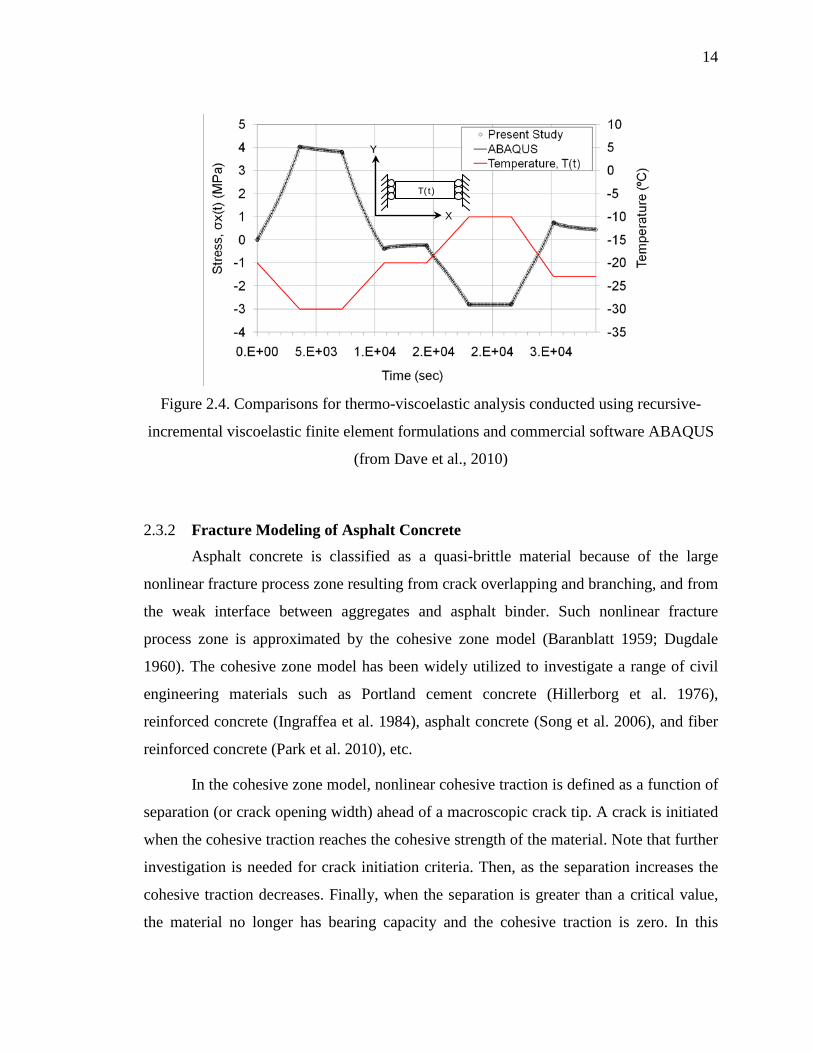
Dave et al. (2010) conducted thermo-viscoelastic verifications to verify the
accuracy of the recursive-incremental viscoelastic finite element formulations in the
context of time dependent temperature conditions and temperature dependent viscoelastic
properties. The boundary value problem simulated in this case is similar to the thermal
stress restrained specimen test (TSRST), which is sometimes used for the evaluation of
thermal cracking performance of asphalt concrete (AASHTO TP-10). In order to ensure
good accuracy for thermal cooling and warming conditions, the temperature boundary
conditions were chosen to impose both warming and cooling events. The results from the
finite element formulations used in this study were compared with the results obtained
from the commercial software ABAQUS. Figure 2.4 shows the variation of temperature
with time as well as the corresponding thermal stresses generated in the restrained
viscoelastic body. The stress response is shown for the formulations and implementation
from the present study as well as those obtained using ABAQUS, showing excellent
agreement.
14
Figure 2.4. Comparisons for thermo-viscoelastic analysis conducted using recursive-
incremental viscoelastic finite element formulations and commercial software ABAQUS
(from Dave et al., 2010)
2.3.2 Fracture Modeling of Asphalt Concrete Asphalt concrete is classified as a quasi-brittle material because of the large
nonlinear fracture process zone resulting from crack overlapping and branching, and from
the weak interface between aggregates and asphalt binder. Such nonlinear fracture
process zone is approximated by the cohesive zone model (Baranblatt 1959; Dugdale
1960). The cohesive zone model has been widely utilized to investigate a range of civil
engineering materials such as Portland cement concrete (Hillerborg et al. 1976),
reinforced concrete (Ingraffea et al. 1984), asphalt concrete (Song et al. 2006), and fiber
reinforced concrete (Park et al. 2010), etc.
In the cohesive zone model, nonlinear cohesive traction is defined as a function of
separation (or crack opening width) ahead of a macroscopic crack tip. A crack is initiated
when the cohesive traction reaches the cohesive strength of the material. Note that further
investigation is needed for crack initiation criteria. Then, as the separation increases the
cohesive traction decreases. Finally, when the separation is greater than a critical value,
the material no longer has bearing capacity and the cohesive traction is zero. In this
T(t)
X
Y

15
study, the bi-linear CZM described by Song et al. (2006) is being employed. This model
has been successfully employed for simulation of thermal and reflective cracking in
asphalt pavements and overlays, for example by Dave et al. (2007, 2008). Additionally,
an intrinsic cohesive zone modeling approach is used; hence a penalty stiffness (i.e.
initial ascending slope) is introduced in the computational implementation. The initial
penalty stiffness is determined on the basis of the numerical stability associated with the
finite element implementation (Roesler et al. 2007).
The material parameters used in the cohesive fracture model are: material strength
( tσ ) and fracture energy ( fG ). Figure 2.5 shows schematically illustration of the bi-
linear cohesive model. The horizontal axis represents the displacement-jump across the
cohesive zone and vertical axis represents the traction. The area under the plot is the
fracture energy ( fG ) and the peak traction is limited to material strength ( tσ ). The
unloading and loading during the course of softening are also shown in the model. The
displacement jump at the complete separation is indicated by critical displacement jump
( Cδ ). The bi-linear cohesive zone model was implemented in the program using a
modified Newton-Raphson solution scheme.
The implementation of the cohesive zone model with recursive incremental
viscoelastic finite element formulations is verified by comparing the results of the finite
element analysis engine with the results of the commercial software ABAQUS. Figure
2.6 illustrates the stress variation with respect to time and shows excellent agreement.
The stress reaches a given cohesive strength (e.g. 2MPa), and decrease to zero while
temperature decreases from 0ºC to -10ºC during 600 sec.

16
Figure 2.5. Bi-linear cohesive zone model
Figure 2.6. Finite element (FE) engine results of the cohesive zone model with recursive
incremental viscoelastic finite element formulations. Temperature linearly decreases from
0ºC to -10ºC during 600 sec.
0.0
0.5
1.0
1.5
2.0
2.5
0 200 400 600
Stre
ss (M
Pa)
Time (sec)
ABAQUSFE Engine
Cohesive elements
Area = Fracture Energy tσ
Tra
ctio
n (M
Pa)
Displacement Jump (mm)
Unloading
Reloading
Cδ

17
2.4
The stand-alone low temperature cracking analysis program developed through
this project was introduced in this chapter. Details on various components of the analysis
modules were presented. The theoretical background for the finite element analysis
program was briefly discussed in this chapter. The graphical user interface (GUI) for the
stand-alone program is described in the following chapter.
Summary

18
CHAPTER 3. VISUAL LTC: A GRAPHICAL USER INTERFACE FOR LOW-TEMPERATURE CRACKING ANALYSIS
3.1
A standalone graphical user interface (GUI), called “Visual LTC”, was
developed for conducting low-temperature cracking analysis and design of asphalt
concrete pavements. A GUI plays an important role in the process of design through use
of sophisticated simulation models which involve complex computations and allows
integration of various design components such as, climatic modeling, determination of
material viscoelastic parameters, non-linear fracture modeling, pavement structure data
handling, etc. Visual LTC unifies several analysis modules in an intuitive, accessible
manner, thereby improving efficiency and productivity of the pavement analysis and
design processes.
Introduction
This chapter provides an overview of the development of and usage of Visual
LTC in sections 3.2 and 3.3, respectively. Future work related to the GUI is discussed in
Section 3.4.
3.2
Visual LTC was written with the object-oriented programming language C#
(pronounced “see-sharp”) under Microsoft’s .NET framework. Upon completion, Visual
LTC will be distributed via the internet, as programs written in C# under the .NET
framework are intended for use as deployable software.
Development of Visual LTC
A simple and intuitive class structure is employed to (1) store material properties
and climatic data, (2) maintain the pavement structure as the user adds and/or modifies

19
layers (i.e. asphalt concrete, base, and subgrade layers), (3) run analysis modules and
display results to the user, and (4) save data and results to a library which can be recalled
during the analysis/design process. The key programming steps of Visual LTC are shown
in Figure 3.1. The following subsections describe the functionality of Visual LTC:
Figure 3.1. Key programming steps of Visual LTC
20
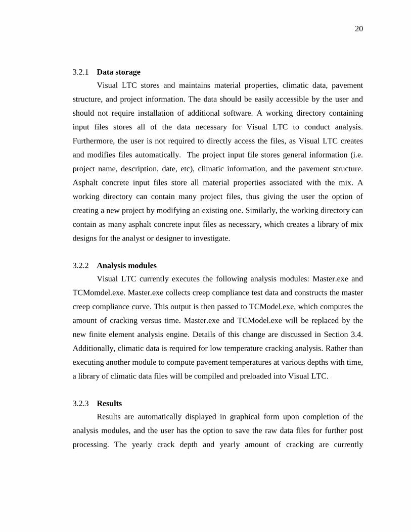
3.2.1 Data storage
Visual LTC stores and maintains material properties, climatic data, pavement
structure, and project information. The data should be easily accessible by the user and
should not require installation of additional software. A working directory containing
input files stores all of the data necessary for Visual LTC to conduct analysis.
Furthermore, the user is not required to directly access the files, as Visual LTC creates
and modifies files automatically. The project input file stores general information (i.e.
project name, description, date, etc), climatic information, and the pavement structure.
Asphalt concrete input files store all material properties associated with the mix. A
working directory can contain many project files, thus giving the user the option of
creating a new project by modifying an existing one. Similarly, the working directory can
contain as many asphalt concrete input files as necessary, which creates a library of mix
designs for the analyst or designer to investigate.
3.2.2 Analysis modules
Visual LTC currently executes the following analysis modules: Master.exe and
TCMomdel.exe. Master.exe collects creep compliance test data and constructs the master
creep compliance curve. This output is then passed to TCModel.exe, which computes the
amount of cracking versus time. Master.exe and TCModel.exe will be replaced by the
new finite element analysis engine. Details of this change are discussed in Section 3.4.
Additionally, climatic data is required for low temperature cracking analysis. Rather than
executing another module to compute pavement temperatures at various depths with time,
a library of climatic data files will be compiled and preloaded into Visual LTC.
3.2.3 Results
Results are automatically displayed in graphical form upon completion of the
analysis modules, and the user has the option to save the raw data files for further post
processing. The yearly crack depth and yearly amount of cracking are currently

21
presented, however this output will be replaced when the finite element analysis engine is
integrated into Visual LTC, see Section 3.4.
3.3
This section briefly demonstrates the use of Visual LTC, which is organized into
five sections:
Use of Visual LTC
Section 1 - Start: The user either opens an existing project or starts a new project.
When an existing project is opened all the inputs are pre-loaded into Visual LTC, but the
user still has capability to alter or change any of the inputs. In case of new project, the
user is required to provide all inputs.
Section 2 – Project Information: The user inputs general information about the
project including project name, location, length of analysis, etc., as shown in Figure 3.2.
The location of analysis corresponds to the locations where climatic data is available.
Figure 3.2. Project information
22
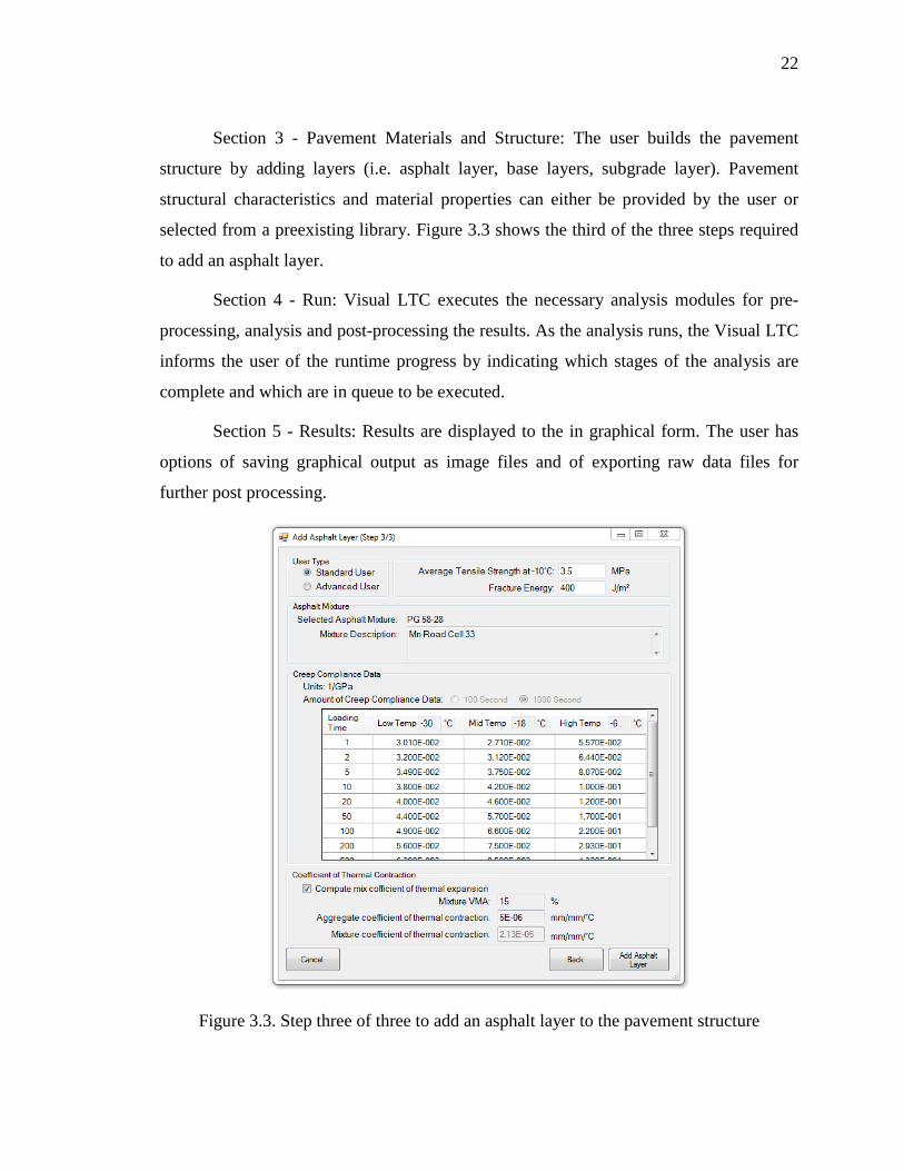
Section 3 - Pavement Materials and Structure: The user builds the pavement
structure by adding layers (i.e. asphalt layer, base layers, subgrade layer). Pavement
structural characteristics and material properties can either be provided by the user or
selected from a preexisting library. Figure 3.3 shows the third of the three steps required
to add an asphalt layer.
Section 4 - Run: Visual LTC executes the necessary analysis modules for pre-
processing, analysis and post-processing the results. As the analysis runs, the Visual LTC
informs the user of the runtime progress by indicating which stages of the analysis are
complete and which are in queue to be executed.
Section 5 - Results: Results are displayed to the in graphical form. The user has
options of saving graphical output as image files and of exporting raw data files for
further post processing.
Figure 3.3. Step three of three to add an asphalt layer to the pavement structure

23
3.4
Visual LTC currently conducts low temperature cracking analysis through
TCModel, however this will be replaced by a more accurate and sophisticated
viscoelastic and cohesive zone finite element analysis engine (described in Chapter-2).
Integration of the new model into Visual LTC will require minor modifications to the
data file structures, for instance fracture parameters will be needed as inputs.
Additionally, communication between Visual LTC and the various analysis modules will
be updated. Note that these changes will not affect the appearance or usage of Visual
LTC from the perspective of the user.
Future work and improvements to Visual LTC
Once the new analysis engine is integrated with Visual LTC, the output displayed
to the user will be different. The new output will be percent of fracture energy dissipated,
extent of pavement thickness damaged and extent of pavement thickness cracked. The
format of the results will still be graphical with the option to save raw data; therefore this
update will be very minor as Visual LTC already has these capabilities.
In addition to the improvements associated with the new analysis engine, the
outputs of the model (i.e. physical damage to the pavement) can be directly used in a
pavement management or asset management system. For instance, cracking amount can
be used to compute maintenance costs, time to the next major rehabilitation, performance
of subsequent overlay cycles, and to future pavement salvage values. To this end, a series
of new graphical user interface pages may be created for asset management inputs and
parameters.

24
CHAPTER 4. DEVELOPMENT OF FRAMEWORK FOR ASSET MANAGEMENT INTEGRATION
4.1
Introduction
The long-term objectives of this research is to truly integrate the ‘hard-side,’ e.g.,
physical pavement modeling and distress prediction software elements, with the ‘soft
side,’ e.g., asset management system software, to create a comprehensive, performance-
based asset management tool for pavement engineers. To this end, a sub-task of this
project was formed, which involved collaboration between the pavements- and
mechanics-oriented research team under the supervision of Professor William Buttlar and
Professor Glaucio Paulino and the systems-oriented research team of Professor Yanfeng
Ouyang of the University of Illinois at Urbana-Champaign. Due to funding constraints,
the major elements of this task were predominantly moved into the third year work plan
for this project. However, initial collaborative brainstorming meetings were conducted,
and a framework for the collaboration was firmly established. A short summary of this
collaborative framework is now presented.
4.2
Background
With shrinking maintenance budgets, the need for accurate, robust asset
management tools are greatly needed for the transportation engineering community.
Furthermore, increases in traffic intensity, vehicular loads, and truck tire stiffness and
changes in the asphalt refining and construction have led led to increased needs for
preventive and rehabilitative maintenance activities. The timing of such activities will
greatly affect the total discounted life-cycle cost of the pavement system.

25
The proposed integrated approach will build upon the work of Ouyang and
colleagues (Ouyang and Madanat, 2004; Ouyang and Madanat, 2006; Ouyang, 2007, and;
Peng and Ouyang, 2010) . In Ouyang and Madanat (2004), a mathematical
programming model providing exact and approximate solutions for optimizing pavement
rehabilitation planning with respect to life-cycle cost was developed. The solution
addressed the ability to model multiple rehabilitation activities across a network of
pavement facilities, based upon a discrete control theory approach. In their work, an
approximate greedy heuristic solution, which has a pseudo-polynomial computational
time, was found to provide efficient, approximate results as compared to the more
rigorous branch-and-bound algorithm approach used. In Ouyang and Madanat (2006), an
analytical solution was provided for the planning problem involving finite-horizon
pavement resurfacing. The optimal resurfacing strategy was proven to have a “threshold
structure,” and it was consistent with the results obtained using the aforementioned
infinite-horizon approach. In this study, pavement roughness1
In Ouyang (2007), a modeling framework was presented for the planning of
pavement resurfacing activities across a highway network based on a continuous
pavement state, discrete time, and infinite horizon approach. In this approach, life-cycle
costs were minimized by solving a multidimensional dynamic programming problem,
which simultaneously considered travelers’ route choices and agency resource allocation
decisions. This and the previously presented models were considered and applied in a
recently completed study with the Illinois Center for Transportation, as part of project
ICT-R27-34 (Peng and Ouyang, 2010). Although these models can directly consider
mechanics-based pavement distress predictions, to date, the models have been developed
with existing, empirically-based distress prediction models.
, and its effect on user
costs was directly considered, which is an important aspect to be considered in the
proposed integrative software program (which is discussed in the following section).
1 Other types of pavement distresses (e.g., those with discrete measurement values) can also be modeled in a similar manner.

26
4.3
Proposed Integration Framework
Considering the available software modeling tools available for: (1) mechanics-
based prediction of thermal cracking based upon asphalt properties (particularly asphalt
grade selection), e.g., as described in chapters 2 and 3, and; (2) comprehensive pavement
management systems modeling, the stage is set for the integration of these two emerging
modeling paradigms in a holistic, performance-based asset management system for
pavement infrastructure.
In the aforementioned studies by Ouyang and collaborators, pavement roughness,
and its effect on user costs were directly considered. This is an important feature, since
the next phase of this study will involve the integration of a mechanics-based thermal
cracking prediction system into a numerical pavement management software program.
Thermal cracking, if fully developed and left untreated, will create an expensive and
recurring maintenance liability. Thermal cracking is a recurring distress in the sense that
it creates an uncontrolled, full-width, full-depth fissure in the pavement structure that will
almost always reflect upwards into subsequently placed asphalt overlays. As the thermal
crack widens, spalls, and permits moisture ingress, pavement roughness and the rate of
pothole development significantly increases. This in turn has a significant effect on user
costs associated with vehicle wear and tear. Thus, the first step in the proposed
integration will be to develop an integrated framework that allows for linking of the new
TCMODEL program with actual pavement cracking, distress and roughness, and to
develop a framework that links the pavement roughness and distress information with
vehicle maintenance and driver comfort.
The proposed work in phase III of this project will also undertake the goal of
extending fundamental predictions of pavement cracking distress to the prediction of
pavement roughness and other forms of deterioration (crack spalling, potholes) as a
function of pavement maintenance, traffic, and climate. This will lead to the
development of an integrated model linking infrastructure condition to vehicle wear-and-
tear and to driver safety. Once complete, this comprehensive model will allow the
designer to base his/her design and maintenance decisions on a life-cycle analysis that

27
will include not only traditional pavement condition considerations, but also the effects of
pavement condition on vehicle operating costs and accident rates. This presents a holistic
approach to pavement design and maintenance, with the ultimate goal of providing the
USDOT with a tool to decrease life cycle costs of a pavement system in a much broader
sense, and moreover, to enhance safety through scientifically informed design and
maintenance decisions.
In order to accomplish these objectives, a series of collaborative meetings were
held between pavement and systems faculty and students at the University of Illinois,
which led to the development of the following future research tasks:
• Development of pavement distress databases for use in model calibration. Most
State DOTs already maintain pavement performance and roughness database; these
databases will be utilized to identify sections for utilization in this study.
• Thermal cracking predictions should be made using the pavement cracking
simulation software (described earlier) for the pavement sections identified in the
previous step.
• Statistical and numerical tools should be utilized to develop a probabilistic
predictive tool that links the cracking information from the simulation software to the
actual pavement cracking and roughness data.
• The probabilistic model should be used to calibrate and validate the pavement
cracking simulation software.
• Calibrated and validated pavement cracking simulation software should be
integrated with the probabilistic model for development of a tool that can be deployed for
prediction of pavement distress (amount of cracking and roughness) caused by thermally
induced cracking.
• Effects of pavement cracking distress on driver comfort and vehicle maintenance
should be studied to create a framework for linking pavement roughness information with
vehicle distress and driver comfort levels.

28
Figure 4.1 outlines the critical steps needed in the next phase of the research as well
as the general research approach. The flow of the project along with various critical steps
and research approaches are discussed next.
Figure 4.1. Project Outline and Major Research Steps
The first step in the proposed phase III study will entail selection of various
pavement sections for which distress data (roughness and cracking) is available along
with other information such as location (for climatic evaluation), traffic, pavement
structural details (layer types, thicknesses etc.), material type etc. Various existing test
sections from the FHWA Pooled Fund Study on Low Temperature Cracking, the LTPP
(Long Term Pavement Performance) Database, IDOT’s Condition Rating System (CRS),
and Mn/ROAD will be utilized along with additional ones from DOTs and local agencies.
Some basic statistics associated with some of the aforementioned pavement performance
Pavement Distress Databases (LTPP, DOTs, Local Agencies)
Selection of Pavement Sections
Simulation of Pavement Sections to Evaluate Cracking Potential
Pavement Cracking Prediction Model
Development of Probabilistic Model for Evaluation of Pavement Distress
(Cracking and Roughness)
Validation and Calibration
Study Effects of Cracking Distress on Vehicle and Driver Behavior

29
databases are: LTPP - Initiated in 1989, over the last 20 year period a total of 2,512
LTPP test sections located throughout the United States and Canada have been included
in the database, and at the end of 2009, a total of 950 test sections were currently active.
The database includes various distresses including transverse cracking and international
roughness index (IRI). MnROAD: Data collection started in 1996; a total of 48 (25
mainline and 23 low-volume) asphalt pavement test cells are present. A total of 75
asphalt pavement test sections have been constructed and tested. Various forms of
distress data are available including surface profile, roughness, crack counts, severity of
cracking, etc. IDOT CRS: Digital video images, IRI, and rut depths are collected on the
entire highway network on a biennial basis, and converted and categorized by type,
extent, and severity of distress. Data is collected using a “Data Collection Vehicle
(DCV)”. This information is utilized to evaluate the condition rating using the CRS.
The next step in the project will include performing the cracking predictions using
the pavement cracking prediction model which is developed jointly through a previous
NEXTRANS project and the FHWA Pooled Fund Study. The cracking prediction model
utilizes a finite element based analysis engine and accounts for asphalt materials bulk
viscoelastic and quasi-brittle cracking behavior. The prediction model integrates the
climatic and structural information to predict the extent of damage and cracking that is
anticipated for a given asphalt pavement system. The output from the prediction model is
in the form of a variety of engineering quantities such as, dissipated fracture energy,
extent of damage and fracture, etc. The next step in the project is a critical one; the
utilization of field performance data (in the form of pavement distress, cracking and
roughness) and correlation with the engineering quantities obtained from the simulation
model. This step is also critical for calibration and validation of the simulation model.
This procedure is illustrated in graphical form in Figure 4.2. The correlation between the
simulation model and the pavement distress and roughness information will be developed
in the form of a probabilistic prediction model that will rely heavily on the use of
statistical tools such as artificial neural networks.

30
Figure 4.2. Development of Probabilistic Model for Distress Prediction
The second critical aspect of this project involves developing a framework for
relating the pavement distress and roughness information with the vehicular distress and
driver comfort and behavior. This type of framework is critical for evaluation of vehicle-
infrastructure and driver-infrastructure interactions. At present, very limited research has
been conducted on this topic, whereby there is gap between researchers working on
topics related to distress of highway infrastructure and interaction between infrastructure
and vehicles and infrastructure and drivers. This framework will allow for future research
to develop a multi-faceted integrated system that links infrastructure renewal,
infrastructure-driver interaction, infrastructure-vehicle interaction, and asset
management. The proposed project will be conducted in a parallel track approach
whereby, the study interaction between pavement distress and drivers and vehicles will
be conducted in parallel with the development of probabilistic model for relating
simulation results with pavement distress predictions.
Pavement Cracking Prediction Model
Probabilistic Model for Distress Prediction
INPUTS: • Pavement Structure • Pavement Material • Project Location • Climatic Conditions
OUTPUTS: • Stresses and Strains • Extent of Damage
and Fracture • Extent of Dissipated
Fracture Energy Calibration and Validation
Pavement Distress Information: • Extent of cracking • Roughness

31
CHAPTER 5. SUMMARY
This chapter summarizes the research, highlights its contributions, and proposes
directions for future research. The stand-alone low temperature cracking analysis
program developed under this project and the National Pooled Fund Study on Low
Temperature Cracking was introduced in Chapter 2. Details on various components of the
analysis modules were presented, including: mesh generation, viscoelastic pavement
response calculation and finite element implementation of the numerical time-integration
scheme, and pavement distress (thermal cracking) simulation via cohesive zone finite
element modeling. The theoretical background for the finite element analysis program
was also briefly presented in Chapter 2. In order to make this comprehensive simulation
model accessible to practitioners and other researchers, a user-friendly graphical user
interface was developed, called ‘Visual LTC.’ Visual LTC, presented in Chapter 3, was
written with the object-oriented programming language C# (pronounced “see-sharp”)
under Microsoft’s .NET framework. A simple and intuitive class structure was employed
to: (1) store material properties and climatic data; (2) maintain the pavement structure as
the user adds and/or modifies layers (i.e. asphalt concrete, base, and subgrade layers); (3)
run analysis modules and display results to the user, and; (4) save data and results to a
library which can be recalled during the analysis/design process. The key programming
steps of Visual LTC were also documented in this report.
Finally, Chapter 4 presented a recently developed framework for the integration of
mechanics-based pavement distress prediction into a comprehensive asset management
system, which will be continued in the upcoming phase III research activities of this
project. The first step in the proposed integration will be to develop an integrated
framework that allows for linking of the new TCMODEL program with actual pavement

32
cracking, distress and roughness, and to develop a framework that links the pavement
roughness and distress information with vehicle maintenance and driver comfort. The
proposed framework will also undertake the goal of extending fundamental predictions of
pavement cracking distress to the prediction of pavement roughness and other forms of
deterioration (crack spalling, potholes) as a function of pavement maintenance, traffic,
and climate. This will lead to the development of an integrated model linking
infrastructure condition to vehicle wear-and-tear and to driver safety. Once complete,
this comprehensive model will allow the designer to base his/her design and maintenance
decisions on a life-cycle analysis that will include not only traditional pavement condition
considerations, but also the effects of pavement condition on vehicle operating costs and
accident rates. This presents a holistic approach to pavement design and maintenance,
with the ultimate goal of providing the USDOT with a tool to decrease life cycle costs of
a pavement system in a much broader sense, and moreover, to enhance safety through
scientifically informed design and maintenance decisions.

33
REFERENCES
G. I. Barenblatt (1959). “The formation of equilibrium cracks during brittle fracture: general ideas and hypotheses, axially symmetric cracks,” Applied Mathematics and Mechanics, Volume 23(3), pp. 622–636. R. M. Christensen (1982). “Theory of Viscoelasticity”. Dover Publications, Inc., Mineola, NY. Q. Dai, and Z. You (2009). “Micromechanical Finite Element Framework for Predicting Viscoelastic Properties of Heterogeneous Asphalt Mixtures,” Materials and Structures, Volume 41(6), pp. 1025-1037. E. V. Dave, S. H. Song, W. G. Buttlar, and G. H. Paulino (2007). "Reflective and Thermal Cracking Modeling of Asphalt Concrete Overlays,” Proceedings of the International Conference on Advanced Characterization of Pavement and Soil Engineering Materials, Taylor and Francis. E. V. Dave, A. F. Braham, W. G. Buttlar, G. H. Paulino, and A. Zofka (2008). “Integration of Laboratory Testing, Field Performance Data, and Numerical Simulations for the Study of Low-Temperature Cracking,” Proceedings of the 6th RILEM International Conference on Cracking in Pavements, Chicago, USA, Eds. Al-Qadi, Scarpas, and Loizos, CRC Press Taylor and Francis Group, New York, ISBN: 978-0-415-4757-54, pp. 369-378. D. S. Dugdale (1960). “Yielding of steel sheets containing slits,” Journal of the Mechanics and Physics of Solids, Volume 8(2), pp. 100–104. A. Hillerborg, M. Modeer, and P. E. Petersson (1976). “Analysis of crack formation and crack growth in concrete by means of fracture mechanics and finite elements,” Cement and Concrete Research, Volume 6(6), pp. 773–781. A. R. Ingraffea, W. H. Gerstle, P. Gergely, V. Saouma (1984). “Fracture mechanics of bond in reinforced concrete,” Journal of Structural Engineering, Volume 110 (4), pp. 871–890.

34
X. Li, M. O. Marasteanu, N. Iverson, and J. F. Labuz (2006). “Observation of Crack Propagation in Asphalt Mixtures with Acoustic Emission,” Transportation Research Record: Journal of Transportation Research Board, Record Number 1970, pp 171-177. R. L. Lytton, J. Uzan, E. G. Femando, R. Roque, D. Hiltunen, and S. M. Stoffels (1993). “Development and Validation of Performance Prediction Models and Specifications for Asphalt Binders and Paving Mixes,” Final Report, Strategic Highway Research Program, Project SHRP-A357, Washington DC. M. Marasteanu, A. Zofka, M. Turos, X. Li, R. Velasquez, X. Li, C. Williams, J. Bausano, W. Buttlar, G. Paulino, A. Braham, E. Dave, J. Ojo, H. Bahia, A. Gallistel, and J. McGraw (2007). “Investigation of Low Temperature Cracking in Asphalt Pavements”, National Pooled Fund Study 776, Minnesota Department of Transportation, Research Services MS 330, St. Paul, MN 55155, 2007. A. Muliana, and K. A. Khan (2008). “A Time-Integration Algorithm for Thermo-Rheologically Complex Polymers,” Computational Materials Science, Volume 41, pp. 576-589. Y. Ouyang, and S. Madanat (2004). “Optimal scheduling of rehabilitation activities for multiple pavement facilities: Exact and approximate solutions,” Transportation Research Part A: Policy and Practice, Volume 38(5), pp. 347-365. Y. Ouyang, and S. Madanat (2006). “An analytical solution for the finite-horizon pavement resurfacing planning problem,” Transportation Research Part B: Methodological, Volume 40(9), pp. 767-778. Y. Ouyang (2007). “Pavement resurfacing planning on highway networks: A parametric policy iteration approach,” Journal of Infrastructure Systems, Volume 13(1), pp. 65-71. P. C. Paris, M. P. Gomez and W. E. Anderson (1961). “A rational analytic theory of fatigue.” The Trend in Engineering. Volume 13, pp. 9-14. K. Park, G. H. Paulino, J. R. Roesler (2010). “Cohesive fracture model for functionally graded fiber reinforced concrete”, Cement and Concrete Research, Volume 40 (6), pp. 956-965. G. H. Paulino, W. G. Buttlar, P. B. Blankenship, M. P. Wagoner, S. H. Song, and E. V. Dave (2006). “Final Report for NSF-GOALI Project - CMS:0219566,” National Science Foundation, Washington, DC, 2006. F. Peng, and Y. Ouyang. “Pavement Program Planning Based On Multi-Year Cost-effectiveness Analysis,” Research Report ICT-10-067, Illinois Center for Transportation, Illinois Department of Transportation, Springfield, IL, 2010.

35
J. R. Roesler, G. H. Paulino, K. Park, and C. Gaedicke (2007). “Concrete fracture prediction using bi-linear softening”, Cement & Concrete Composites, Volume 29, pp. 300-312. R. Roque, D. R. Hiltunen, W. G. Buttlar. (1995a) “Thermal Cracking Performance and Design of Mixtures Using Superpave(TM),” Journal of the Association of Asphalt Paving Technologists, Volume 64, pp. 718-735. R. Roque, D. Hiltunen, W. Buttlar, T. Farwana. (1995b) “Engineering Properties of Asphalt Mixtures and the Relationship to their Performance,” STP1265 Engineering Properties of Asphalt Mixtures and the Relationship to their Performance, ASTM International. S. H. Song, G. H. Paulino, and W. G. Buttlar. (2006) “A Bilinear Cohesive Zone Model Tailored for Fracture of Asphalt Concrete considering Rate Effects in Bulk Materials,” Engineering Fracture Mechanics, Volume 73, Number 18, pp. 2829-2848. M. P. Wagoner, W. G. Buttlar, and G. H. Paulino. (2005) "Disk-Shaped Compact Tension Test for Asphalt Concrete Fracture", Experimental Mechanics, Volume 45, pp. 270-277. S. Yi and H. H. Hilton (1994). “Dynamic Finite Element Analysis of Viscoelastic Composite Plates in the Time Domain.” International Journal of Numerical Methods in Engineering, Volume 37(12), pp. 4081-4096. M. A. Zocher, S. E. Groves, and D. H. Allen (1997). “A Three-Dimensional Finite Element Formulation for Thermoviscoelastic Orthotropic Media.” International Journal of Numerical Methods in Engineering, Volume 40(12), pp. 2267-2288.