thermal-barrier coatings for more efficient gas-turbine ... · technology and high-temperature...
TRANSCRIPT

Vo
l. 37, No
. 10, 873–976M
RS
BU
LLET
INT
herm
al-barrier co
ating
s for m
ore effi
cient g
as-turb
ine en
gin
esO
ctob
er 2012
October 2012 Vol. 37 No. 10 www.mrs.org/bulletin
Thermal-barrier coatings for more efficient gas-turbine engines
ALSO IN THIS ISSUE Scanning transmission electron microscopy: Seeing the atoms more clearly
891MRS BULLETIN • VOLUME 37 • OCTOBER 2012 • www.mrs.org/bulletin© 2012 Materials Research Society
Introduction Thermal-barrier coatings (TBCs) are refractory-oxide ceramic
coatings applied to the surfaces of metallic parts in the hottest
part of gas-turbine engines ( Figures 1 and 2 ), enabling mod-
ern engines to operate at signifi cantly higher gas temperatures
than their predecessors (see recent reviews 1–6 ). Gas-turbine
engines, used to propel aircraft and to generate electricity,
are Carnot engines where their effi ciency and core power are
directly related to the gas temperature entering the turbine
section. 7,8 Further increases in the energy effi ciency of gas-
turbine engines, both to increase the electricity output and,
for jet engines, the thrust-to-weight ratio and durability, will
rely on further improvements in TBCs. At the same time, as
gas temperatures are increased in the pursuit of higher engine
effi ciency, there are new challenges to existing TBCs.
To place this in context, gas-turbine engines are a $42 billion
industry worldwide (2010), with ∼ 65% of the sales accounting
for jet engines and the remainder land-based engines for elec-
tricity generation. 9 The latter, fueled by natural gas or liquid
fuels, produce ∼ 25% of all electricity in the United States and
∼ 20% worldwide (2010). 10 With the anticipated worldwide
growth of electricity demand and the recent discovery of
vast shale gas resources, the number of gas-turbine engines in
service will inevitably grow in the coming decades. 9 Similarly,
airline traffi c is expected to double in the next 20 years, 11 while
at the same time, there is a need to reduce high-altitude NO x
pollution produced by jet engine exhausts. 12 Together, these
developments will require continued innovation in gas turbine
technology and high-temperature engine materials, including
TBCs and associated technologies.
Many engineering design factors infl uence the overall
effi ciency of gas-turbine engines, but a major step in increasing
engine temperature and engine effi ciency was the introduction
of TBCs. Typically made of ∼ 7 wt% Y 2 O 3 -stabilized ZrO 2(7YSZ) ceramics, TBCs provide thermal insulation to the
metallic/superalloy engine parts. These parts include the com-
bustor ( Figures 1 and 2 ); stationary guide vanes, rotating blades
( Figure 1 ), blade outer air-seals, and shrouds in the high-pressure
section behind the combustor; and afterburners in the tail section
of jet engines. As illustrated in Figure 3 , the gas-temperature
increase facilitated by the use of TBCs, in conjunction with
innovative air-cooling approaches, has been much greater than
that enabled by earlier materials development, including the
development of single-crystal Ni-based superalloys.
Originally, TBCs were introduced to extend the useful life
of stationary engine parts such as the combustor, but in the late
1980s, TBCs were fi rst used on rotating blades. 13 However,
TBCs were not “prime reliant”; in other words, the ceramic
coating was not considered in the design of the temperature
capability of the underlying metal parts. Today, TBCs are crit-
ical components in gas-turbine engines, and because the gas
temperatures are typically higher than the melting point of
Thermal-barrier coatings for more effi cient gas-turbine engines David R. Clarke , Matthias Oechsner , and Nitin P. Padture , Guest Editors
Gas-turbine engines used in transportation, energy, and defense sectors rely on high-temperature
thermal-barrier coatings (TBCs) for improved effi ciencies and power. The promise of still
higher effi ciencies and other benefi ts is driving TBCs research and development worldwide.
An introduction to TBCs—complex, multi-layer evolving systems—is presented, where these
fascinating systems touch on several known phenomena in materials science and engineering.
Critical elements identifi ed as being important to the development of future TBCs form the
basis for the fi ve articles in this issue of MRS Bulletin . These articles are introduced, together
with a discussion of the major challenges to improved coating development and the rich
opportunities for materials research they provide.
David R. Clarke, School of Engineering and Applied Sciences , Harvard University ; [email protected] Matthias Oechsner, Center for Structural Materials , Technische Universitaet Darmstadt , Germany ; [email protected] Nitin P. Padture, School of Engineering , Brown University ; [email protected] DOI: 10.1557/mrs.2012.232
THERMAL-BARRIER COATINGS FOR MORE EFFICIENT GAS-TURBINE ENGINES
892 MRS BULLETIN • VOLUME 37 • OCTOBER 2012 • www.mrs.org/bulletin
the underlying metal parts, any TBC failure can endanger the
engine. 14 Furthermore, because of the coupled diffusional and
mechanical interactions between the oxide ceramic coating and
the underlying alloys at these high temperatures, it is essential
to consider TBCs as a complex, interrelated, and evolving mate-
rial system, consisting not only of the oxide ceramic coating
(topcoat) itself but also the underlying superalloy engine part,
and two other layers in between. These include a metallic bond-
coat layer that is more oxidation resistant than the superalloy,
and a thin, thermally grown oxide (TGO) layer that forms
between the topcoat and the bond coat as result of bond-coat
oxidation in-service. The bond-coat composition is designed
to result in a TGO made of α -Al 2 O 3 —a mechanically robust,
effective barrier to oxygen diffusion. Figure 4 illustrates this
multilayer structure in a typical TBC system.
During service, several kinetic processes occur in parallel.
Interdiffusion between the bond coat and the underlying super-
alloy occurs, driven by chemical potential gradients; Al diffuses
from the bond coat to form the TGO; and microstructural,
chemical, and phase changes occur in all the
materials, including in the ceramic topcoat
itself, changing their very properties. Since
all of these are thermally activated processes,
the rates at which they occur are expected to
increase exponentially with temperature, albeit
with different activation energies. Furthermore,
the processes generally lead to degradation and
failure of the coating.
TBCs are also multifunctional: they must
provide thermal insulation to protect the under-
lying superalloy engine parts, have strain compli-
ance to minimize thermal-expansion-mismatch
stresses with the superalloy parts on heating
and cooling, and must also refl ect much of the
radiant heat from the hot gas, preventing it from
reaching the metal alloy. Furthermore, TBCs
must maintain thermal protection for prolonged
service times and thermal cycles without failure.
Typically, these times are 1000s of hours for jet
engines being cycled numerous times between
a maximum temperature of ∼ 1300°C and room
temperature (takeoff/landing and on-ground),
and 10,000s of hours for power-generation
engines with fewer thermal cycles (maintenance
shut-downs). However, the latter are now being
increasingly employed to stabilize the electric
grid connected to renewable sources (wind,
solar), and, thus, these engines experience more
frequent cycles to compensate for the inherent
intermittency of renewables. TBCs need to do
this without separating from the engine parts
while also withstanding extreme thermal gradients
( ∼ 1°C μ m –1 ) and energy fl uxes ( ∼ 1 MW m –2 ). Not
only are these demands extremely exacting but
also are often confl icting: TBCs must have both
low thermal conductivity and low weight; they must remain
intact while withstanding large stress variations, both due to
heating and cooling as well as under thermal shock; they must
be chemically compatible with the underlying metal and the
TGO; and they must operate in an oxidizing environment at
maximum pressures of ∼ 10 atmospheres and maximum gas
velocities exceeding Mach 1.
These demands and the desire to operate at higher tempera-
tures reliably for longer times are driving new TBC innovations
based on exploration of the underlying materials, processing
sciences, and mechanistic understanding of degradation/failure
and its mitigation. Several but not all of these key areas are
highlighted in this issue of MRS Bulletin .
In this issue Ceramic topcoat processing Sampath et al. describe the oxide ceramic topcoat deposition
processes and microstructures. Unlike more traditional thin
fi lms used in microelectronics and in materials-growth studies,
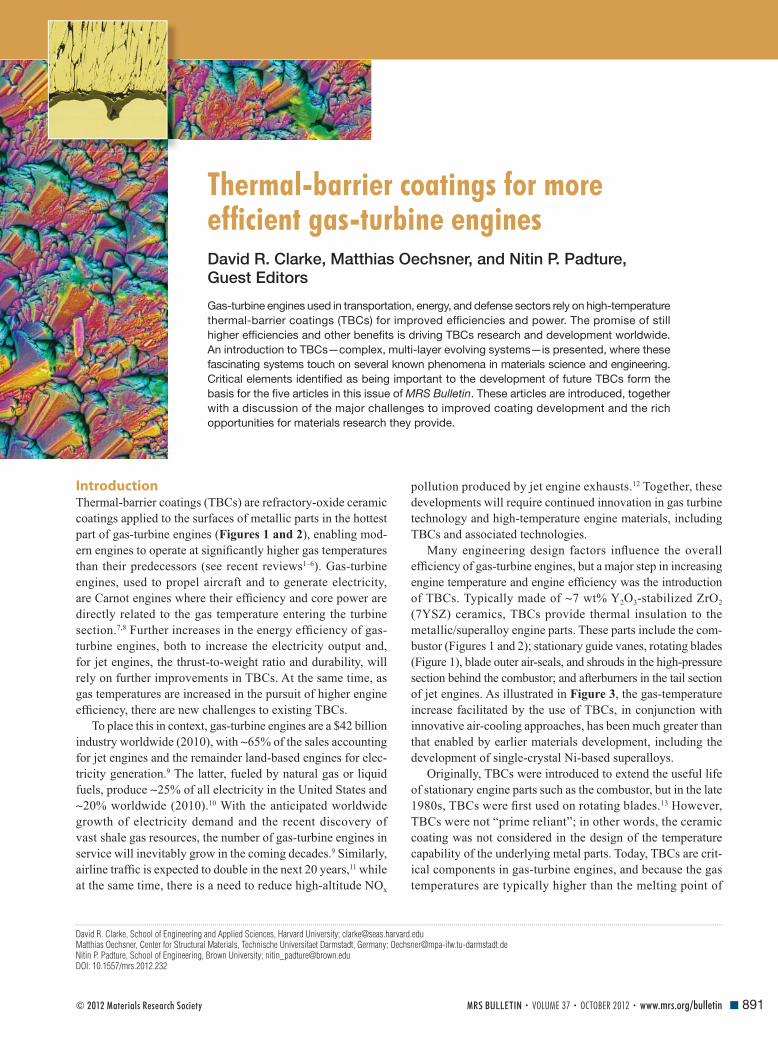
Figure 1. Cutaway view of Engine Alliance GP7200 aircraft engine, photograph of a
turbine blade ( ∼ 10 cm long) with thermal-barrier coating (TBC) from the high-pressure hot
section of an engine, and a scanning electron microscope (SEM) image of a cross-section
of an electron beam physical vapor deposited 7 wt% yttria-stabilized zirconia TBC. (Engine
image courtesy of Engine Alliance, turbine blade photograph courtesy of YXLON, and the
SEM micrograph is from Reference 44.) TGO, thermally grown oxide.

THERMAL-BARRIER COATINGS FOR MORE EFFICIENT GAS-TURBINE ENGINES
893MRS BULLETIN • VOLUME 37 • OCTOBER 2012 • www.mrs.org/bulletin
these coatings are of intermediate thickness (100 μ m to 1 mm),
and they must be deposited at a high rate to incorporate porosity.
Typical TBC porosity is ∼ 15%, which is essential for high strain
compliance and reduced thermal conductivity, yet the TBCs
need to be mechanically robust to resist fracture, erosion, and
foreign object damage (FOD). Furthermore, TBCs need to be
deposited on complex-shaped parts with highly curved surfaces,
and at the same time the TBCs must have reproducible thermal
and mechanical properties. Currently, TBCs are deposited by
air plasma-spraying (APS) 15 or by electron beam physical vapor
deposition (EBPVD). 16 Typically, the low-cost APS method is
used to deposit TBCs on stationary engine parts (combustor,
shroud, vanes), whereas EBPVD TBCs are used on the most
demanding hot-section parts in jet engines such as blades and
vanes. Today, both stationary and rotating hot-section parts
in electricity-generation engines, which tend to be much larger
than those in jet engines, use APS TBCs. The microstructures of
APS and EBPVD TBCs are vastly different (see Figures 1 and 2 ),
and each offer different advantages in terms of properties and
performance. While processing science and technology of
depositing 7YSZ TBCs is well established, the widespread
introduction of improved TBCs of alternative compositions will
ultimately depend on their reproducible and successful deposi-
tion commercially. Alternative TBC deposition methods with
added advantages and versatilities are also being pursued. 17 – 20
TBCs testing and evaluation An equally big hurdle to developing improved TBCs is the
sheer complexity and variety of failure modes and their depen-
dence on engine operating conditions. Superfi cially, the failures
are similar; the coating spalls off the engine part exposing the
underlying metal to rapid oxidation or melting. However, a
variety of mechanisms can be responsible for the observed
failure. 1 In some instances, the TGO grows to exceed a critical
thickness and spalls off, causing TBC failure. 21 , 22 In others,
the initially fl at bond coat and TGO undergo a complex mor-
phological instability—“rumpling” ( Figure 5 )—causing local
separations that grow in size with thermal cycling until linking
up to form a spall. 23 – 25 In still others, cavitation occurs in the
bond coat and grows under thermal cycling. 26 In each of these
cases, the failure location depends on the actual thermal and
mechanical loading conditions in the coating. Typically, at
moderate heat fl uxes but high temperatures at the bond coat,
failure is dominated by processes related to TGO formation
and bond-coat inelastic behavior, where fracture occurs in the
bond-coat/topcoat interface region. With increasing topcoat
surface temperature and thermal-gradient, thermal-expansion
mismatch starts to play a more dominant role, and fracture
location typically shifts to within the ceramic topcoat.
In some cases, spallation occurs as a result of impact from
particles (FOD) carried along with the hot, combusted gas. 27 In
other cases, thermal-shock spallation of the coating can occur
Figure 2. (a) Photograph of an annular combustor with thermal-
barrier coating (TBC) and (b) cross-sectional scanning electron
microscopy image showing an air plasma-sprayed 7 wt%
yttria-stabilized zirconia TBC. 2 TGO, thermally grown oxide.
Combustor image courtesy of Siemens Energy Inc.
Figure 3. Progression of temperature capabilities of Ni-based
superalloys and thermal-barrier coating (TBC) materials over
the past 50 years. The red lines indicate progression of
maximum allowable gas temperatures in engines, with the large
increase gained from employing TBCs. Based on a diagram
from the late Professor Tony Evans.

THERMAL-BARRIER COATINGS FOR MORE EFFICIENT GAS-TURBINE ENGINES
894 MRS BULLETIN • VOLUME 37 • OCTOBER 2012 • www.mrs.org/bulletin
during rapid cooling. In still other cases, fi ne sand and particu-
lates ingested into the engine (including volcanic ash) can melt
into a silicate glass at high temperatures (>1200°C) on the TBC
surface and wick into the TBC, decreasing its strain compliance
and causing spallation upon cooling.
Both the crack driving force and the fracture resistance
offered by the material also depend on the mechanical and
thermophysical properties of the TBC system. These can change
signifi cantly with time at temperature. Also, these properties
can be infl uenced signifi cantly by the coating microstructure,
which in turn is infl uenced by the process parameters used during
the coating deposition. Even small variations of these parameters
can lead to signifi cant changes in coating microstructure, and thus
to a wide variation in mechanical and thermophysical properties,
resulting in a large scatter in system reliability, durability, and
predictability. Thus, deterministic approaches for predicting
TBC life can be often misleading, requiring the use of probabi-
listic approaches for predicting TBC life. From a manufacturing,
as well as materials selection perspective, clarifying mechanisms
of failure and being able to predict life remains an essential and
central task in optimizing the coating system.
This has motivated the development of TBC testing methods
and non-destructive evaluation techniques, especially under
realistic conditions pertinent to engine operation, which can
include high pressures (up to 10 atm.), high temperatures
(up to 1400°C), steep thermal gradients (temperature differences
up to 300°C), high gas velocities, and the presence of detrimental
environmental species (e.g., water vapor, sand, ash, salt). The
article by Va β en et al. describes some of the common TBC
failure modes and innovations in TBC testing and evaluation.
Topcoat ceramics The majority of TBCs in use today are ZrO 2 -based having
a composition containing ∼ 7 wt% Y 2 O 3 (7YSZ). Originally,
this ceramic was selected empirically based on
its low thermal conductivity, high melting
point, resistance to sintering, a demonstrated
manufacturing capability for depositing it with
constant composition, and long life in the result-
ing TBCs. 13 , 28 – 30 Unlike the cubic ZrO 2 used in
oxide fuel cells, oxygen sensors, and fake dia-
monds, which have higher Y 2 O 3 content, 7YSZ
is a metastable tetragonal phase (t’). 4 7YSZ has
been shown to have unusually high fracture
toughness due to ferroelastic toughening. 31 , 32
Unlike other transformation-toughened ZrO 2 -
based ceramics, so-called “ceramic steels,” 33
used in bearings, cutting tools, and knives, the
toughness in 7YSZ does not arise from the
martensitic transformation (an irreversible and
diffusionless collective movement of atoms)
from the tetragonal to monoclinic phase but
rather from reversible ferroelastic domain
switching from one tetragonal variant to another
when stressed. 31 , 32 Also, unlike transformation
toughening, ferroelastic toughening can operate at high tem-
peratures, typical of those at engine temperatures. High fracture
toughness in TBCs is important not only for resisting impact
and erosion but also spallation.
Despite these intrinsic advantages, there is a worldwide
search under way for oxides with superior, high-temperature
properties that could replace 7YSZ. Much of this activity is
presently directed to identifying oxides with lower thermal
conductivity, 34 as discussed in the article by Pan et al. Although
the underlying physics of thermal conductivity in solids was
fi rmly established more than 30 years ago, the challenge is to
translate the concepts to identify prospective low conductivity
compounds in terms of crystal structure and bonding, especially
when little or nothing is known about the phonon (lattice wave)
properties of almost all poly-ionic oxides. The bulk of heat
transport in these oxides occurs via phonons, and their scatter-
ing governs the oxide thermal resistance. Fortunately, at high
temperatures, the majority of lattice phonons can be expected to
be fully thermally activated, so classical descriptions of thermal
conductivity can guide the search for low conductivity oxides.
This search has, for instance, revealed that natural superlattice
structures have exceptionally low thermal conductivity 35 – 37 as do
oxides with a large number of ions per unit cell that also can exhibit
extensive solid solution. 38 Another insight, gained from molecular
dynamics simulations, is that in YSZ, phonons are highly delocal-
ized and transport diffusively, akin to a phonon glass, despite
the crystal perfection measured by x-ray diffraction. 39
Bond-coat alloys and oxidation In many respects, the most stringent constraints are imposed
on the bond coat. Its primary function is to provide a reservoir
from which Al can diffuse to form a protective α -Al 2 O 3 TGO
while maintaining cohesion with the TBC without reacting
with it. Mechanics modeling 40 indicates that, ideally, the TGO
Figure 4. Schematic illustration of the multilayer, multifunctional nature of the thermal-
barrier coating system (not to scale). The ceramic topcoat is deposited by electron beam
physical vapor deposition (EBPVD) or air plasma-spraying (APS). Sandwiched between
the topcoat and the metallic bond coat is the thermally grown oxide (TGO). Properties/
functions and approximate thicknesses of the different layers are indicated.

THERMAL-BARRIER COATINGS FOR MORE EFFICIENT GAS-TURBINE ENGINES
895MRS BULLETIN • VOLUME 37 • OCTOBER 2012 • www.mrs.org/bulletin
should remain elastic to the highest temperatures and not creep
to prevent “rumpling” 23 , 24 or cavitation on thermal cycling 26 that
can, in turn, lead to the development of local separations at the
TBC interface ( Figure 5 ). 25 At the same time, it has to operate
at the highest temperature possible to minimize the amount of
air used to cool the vanes and blades, without reacting with
the underlying superalloy and melting. This presently implies
that the maximum bond-coat temperature cannot be allowed to
exceed ∼ 1150°C. Currently, there are two main bond-coat alloys
in use, a Ni-rich nickel aluminide and a compositionally more
complex MCrAlY (M=Ni, Co+Ni, or Fe) alloy. While these are
very different alloys metallurgically, the challenges are similar,
as described in the article by Pollock et al.: how to minimize
deformation at intermediate and operating temperatures, how
to minimize interdiffusion with the underlying
superalloy to prevent the formation of brittle
intermetallics, and how to deliver critical ele-
ments in addition to Al, such as Hf and Y, to the
growing TGO to minimize its inelastic plastic
deformation under thermal cycling.
Critical to understanding the performance of
the TBC system is the formation, growth, and
properties of the TGO that forms underneath
the 7YSZ topcoat by oxidation of the bond-
coat alloy (TBC microstructures are highly
defective with porosity and cracks, and 7YSZ
is an oxygen conductor, hence oxidation of the
bond coat cannot be prevented). The bond-coat
compositions are selected to form an α -Al 2 O 3
TGO because it is the slowest growing oxide
at high temperatures and forms an impervious,
adherent layer with excellent mechanical integ-
rity. This is important because TBC failure can
occur when the TGO growth exceeds a critical
thickness. The essential mechanics of this form
of failure are similar to the origin of a critical
thickness for the loss of coherence of epitaxial
thin fi lms, namely when the release of stored
elastic strain energy in the growing fi lm exceeds
the fracture resistance. 41 There are two contribu-
tions to the stress in the TGO, one is associated
with the growth strain as new oxide is created at
the grain boundaries of the TGO, and the other is
the mismatch stress with the superalloy generated
by differences in thermal expansion on cooling.
The growth strain consists of two components:
one that leads to a simple thickening and the
other that motivates lateral expansion of the
TGO that, in turn, drives out-of-plane instabil-
ities as well as other mechanical responses. 40
The origin of the lateral growth strain is poorly
understood but is generally attributed to the
counter-diffusion of inward diffusing O 2– and
outward diffusing Al 3+ , resulting in the plating
out of new Al 2 O 3 in the TGO grain bounda-
ries. 42 There have been a limited number of measurements of
the growth strain in the TGO absent the TBC itself using x-ray
synchrotron sources 43 but not nearly enough to follow the evo-
lution during oxidation or thermal cycling. More revealing have
been non-contact measurements by photoluminescence piezo-
spectroscopy of the strains measured through the topcoat. 44 In
this technique, a laser beam is used to penetrate through the
topcoat and excite the R -line luminescence from trace Cr 3+ ions
invariably present in the TGO. The local mean stress in the
TGO is proportional to the frequency shift of the R -lines. This
has enabled correlations to be mapped between luminescence
shifts and the development of local damage as the bond coat
and TGO rumple, as shown in Figures 5 and 6 . 23 , 25 , 45 There
remain several important unresolved questions about the lateral
Figure 5. (a) Cross-sectional scanning electron microscopy images showing the
progression of thermally grown oxide (TGO) thickening and the evolution of local interface
separations in an electron beam physical vapor deposited 7 wt% yttria-stabilized zirconia
thermal-barrier coating (TBC) on a Pt-modifi ed nickel aluminide bond coat with number of 1-h
thermal cycles (1150°C peak temperature). (b) The plot shows the mean stress in the TGO
stress measured through the topcoat using the photoluminescence piezo-spectroscopy
technique. The different symbols refer to measurements on different coatings from the
same deposition run. (Based on information from Reference 25.)
THERMAL-BARRIER COATINGS FOR MORE EFFICIENT GAS-TURBINE ENGINES
896 MRS BULLETIN • VOLUME 37 • OCTOBER 2012 • www.mrs.org/bulletin
growth strain whose resolution could impact oxidation of other
metallic alloys. These include how minor elements, at the ppm
level and above, affect the growth and mechanical behavior of
the TGO. Of particular interest are the elements Y, Zr, and Hf
that segregate, on account of their large ionic radii, to the grain
boundaries of the TGO. Among the key questions being raised
are whether these elements alter the counter-diffusion along the
TGO grain boundaries that creates the lateral growth strain and
how they affect the high-temperature creep and plasticity of the
TGO. It is known that rare-earth ions dramatically increase the
creep resistance of alumina ceramics. 46
Attack by molten deposits and its mitigation Higher engine temperatures are also creating new
materials issues in ceramic topcoats, namely
degradation of 7YSZ TBCs due to molten
silicate deposits, 47 – 52 formed by the ingestion of
fi ne particulates from the environment (sand, 49
volcanic ash 53 , 54 ) (see the Levi et al. article in
this issue). Because of the major components
in the silicate glass formed, this phenomenon
is commonly referred to as CMAS (calcium-
magnesium-alumino-silicate) attack. This pri-
marily affects high-performance jet engines on
account of their higher maximum temperatures
and electricity-generation engines in some loca-
tions, but it will likely affect more engines as
operation temperatures are increased in pursuit
of greater engine effi ciencies. In the case of
land-based electricity-generation engines, it is
not always practical to fi lter out the fi nest parti-
cles that can be carried along with the input air
and from alternative fuels such as syngas. 55 , 56
It appears that wetting of TBCs by the molten
CMAS glass, and dissolution/reprecipitation
of YSZ grains in that glass, contribute to the
CMAS attack of 7YSZ TBCs. 50 , 51 This manifests
itself as continued penetration of the CMAS glass
into the TBC and affects both APS and EBPVD
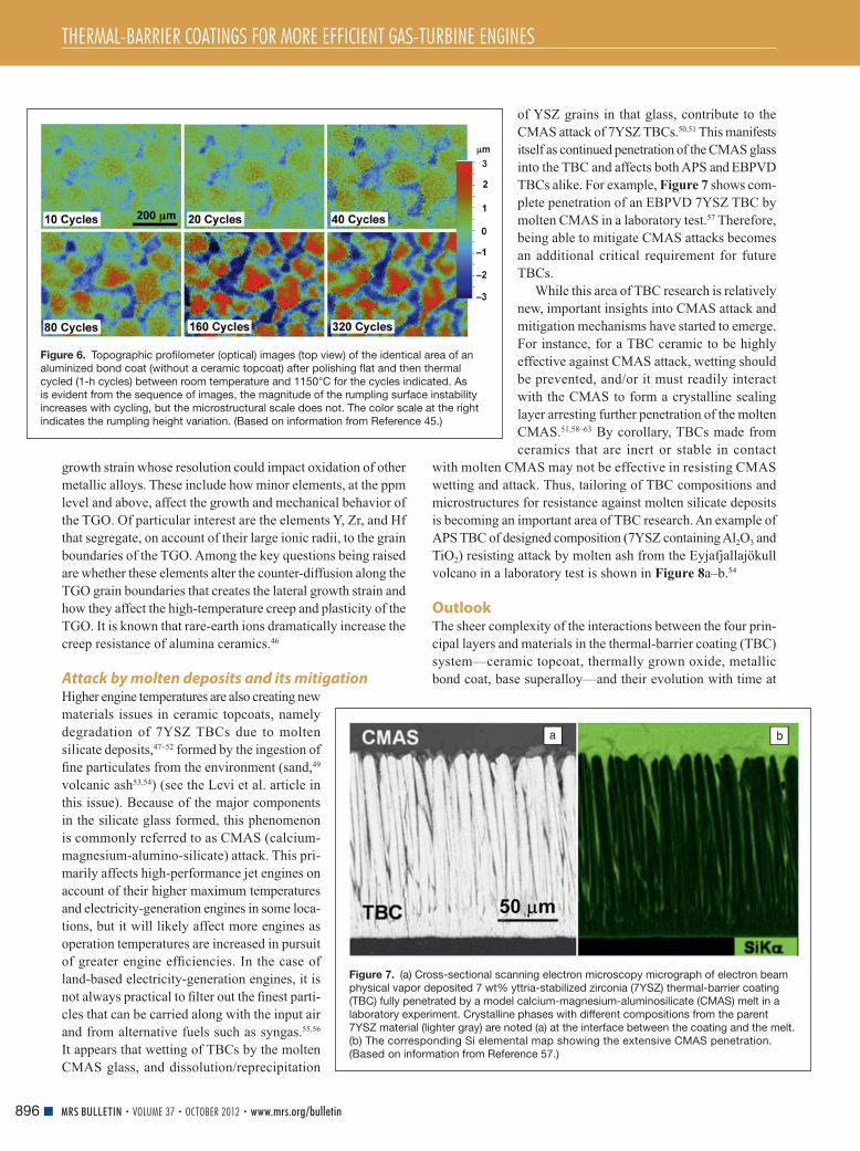
TBCs alike. For example, Figure 7 shows com-
plete penetration of an EBPVD 7YSZ TBC by
molten CMAS in a laboratory test. 57 Therefore,
being able to mitigate CMAS attacks becomes
an additional critical requirement for future
TBCs.
While this area of TBC research is relatively
new, important insights into CMAS attack and
mitigation mechanisms have started to emerge.
For instance, for a TBC ceramic to be highly
effective against CMAS attack, wetting should
be prevented, and/or it must readily interact
with the CMAS to form a crystalline sealing
layer arresting further penetration of the molten
CMAS. 51 , 58 – 63 By corollary, TBCs made from
ceramics that are inert or stable in contact
with molten CMAS may not be effective in resisting CMAS
wetting and attack. Thus, tailoring of TBC compositions and
microstructures for resistance against molten silicate deposits
is becoming an important area of TBC research. An example of
APS TBC of designed composition (7YSZ containing Al 2 O 3 and
TiO 2 ) resisting attack by molten ash from the Eyjafjallajökull
volcano in a laboratory test is shown in Figure 8 a–b. 54
Outlook The sheer complexity of the interactions between the four prin-
cipal layers and materials in the thermal-barrier coating (TBC)
system—ceramic topcoat, thermally grown oxide, metallic
bond coat, base superalloy—and their evolution with time at
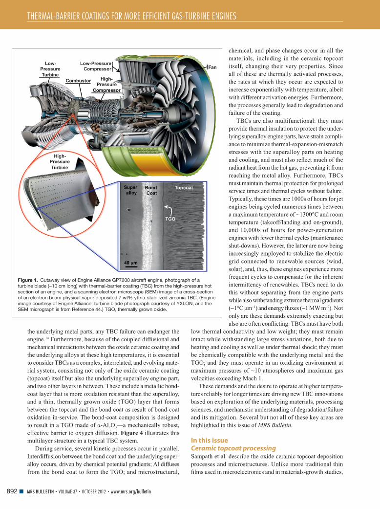
Figure 6. Topographic profi lometer (optical) images (top view) of the identical area of an
aluminized bond coat (without a ceramic topcoat) after polishing fl at and then thermal
cycled (1-h cycles) between room temperature and 1150°C for the cycles indicated. As
is evident from the sequence of images, the magnitude of the rumpling surface instability
increases with cycling, but the microstructural scale does not. The color scale at the right
indicates the rumpling height variation. (Based on information from Reference 45.)
Figure 7. (a) Cross-sectional scanning electron microscopy micrograph of electron beam
physical vapor deposited 7 wt% yttria-stabilized zirconia (7YSZ) thermal-barrier coating
(TBC) fully penetrated by a model calcium-magnesium-aluminosilicate (CMAS) melt in a
laboratory experiment. Crystalline phases with different compositions from the parent
7YSZ material (lighter gray) are noted (a) at the interface between the coating and the melt.
(b) The corresponding Si elemental map showing the extensive CMAS penetration.
(Based on information from Reference 57.)

THERMAL-BARRIER COATINGS FOR MORE EFFICIENT GAS-TURBINE ENGINES
897MRS BULLETIN • VOLUME 37 • OCTOBER 2012 • www.mrs.org/bulletin
temperature make it essential that synergistic progress be made
in all areas to enable TBCs to operate reliably at still higher
temperatures in the future. Three major challenges stand out.
The fi rst is to increase the reproducibility of the coating deposi-
tion so that full temperature capabilities of existing TBCs can
be utilized with greater confi dence. Indeed, at present, engine
designers only take into account about half of the possible tem-
perature increase afforded by the thermal properties of current
TBCs because of the lack of processing reproducibility. The
second challenge is to have more comprehensive modeling
of the evolution of the coating system and its failure, as well
as a better description of the material properties, especially
at high temperatures. This will require a concerted modeling
effort spanning multiple length and temporal scales, sup-
ported by experimental validation that will greatly benefi t
the development and implementation of future TBCs. The
third major challenge is tackling new issues that arise with
higher temperatures. One such issue is radiative heat transport
through the TBC. New approaches will be needed to refl ect
and/or scatter radiation and prevent it from reaching the
metallic parts. Another important issue is calcium-magnesium-
alumino-silicate (CMAS) attack and its mitigation. This will
require new TBC compositions and microstructures that not
only resist CMAS penetration but also meet a suite of other
requirements at those higher temperatures.
While the use of TBCs has already resulted in dramatic
improvements in the effi ciency and the power output of gas-turbine
engines, the challenges described in this and the companion
articles present new materials research opportunities essential
for turbine engine designers to take full advantage of recent
advances in materials, processing, and reliability. This will
become even more crucial in bridging the growing energy and
transportation demands of society until large scale energy
generation from renewable sources (solar, wind) becomes
economically more viable. Indeed, because gas turbines already
play a major role in electricity generation and aircraft pro-
pulsion, even minor improvements in engine effi ciency will
have an immediate and signifi cant positive
impact on the overall energy portfolio of the
world.
Acknowledgments D.R.C. is grateful for the long-term support of
his research in TBCs from the Offi ce of Naval
Research. M.O. acknowledges the German
Research Society (DFG) and the Forschungs-
vereinigung Verbrennungskraftmaschinen e.V.
(FVV-6011081). N.P.P. is grateful for continued
support from the Offi ce of Naval Research and
the Department of Energy for his research in
the area of TBCs. We acknowledge the contri-
butions of all the authors in this theme issue and
discussions with several others too numerous
to list.
References 1. A.G. Evans , D.R. Mumm , J.W. Hutchinson , G.H. Meier , F.S. Pettit , Prog. Mater. Sci. 46 , 505 ( 2001 ). 2. N.P. Padture , M. Gell , E.H. Jordan , Science 296 , 280 ( 2002 ). 3. C.G. Levi , Curr. Opin. Solid State Mater. Sci. 8 , 77 ( 2002 ). 4. D.R. Clarke , C.G. Levi , Annu. Rev. Mater. Sci. 33 , 383 ( 2003 ). 5. A.G. Evans , D.R. Clarke , C.G. Levi , J. Eur. Ceram. Soc. 28 , 1405 ( 2008 ). 6. R. Vaßen , M. Ophelia-Jarligo , T. Steinke , D. Emil-Mack , D. Stöver , Surf. Coat. Technol. 205 , 938 ( 2010 ). 7. W.W. Bathie , Fundamentals of Gas Turbines—Second Edition ( Wiley , New York , 1996 ). 8. J.H. Perepezko , Science 326 , 1068 ( 2009 ). 9. L.S. Langston , Mech. Eng. 133 , 30 ( 2011 ). 10. US Energy Information Administration , Annual Energy Review ; www . eia . gov / totalenergy / data / annual / index . cfm ( accessed June 2012 ). 11. Federal Aviation Administration , FAA Forecast Predicts Air Travel to Double in Two Decades ; www . faa . gov / news / press_releases / news_story . cfm ? newsId = 12439 ( accessed June 2012 ). 12. International Civl Aviation Organization , ICAO Environment Report , www . icao . int / environmental - protection / Pages / EnvReport10 . aspx ( accessed June 2010 ). 13. U. Schulz , K. Fritscher , C. Leyens , M. Peters , W.A. Kaysser , JOM 49 ( 1997 ). 14. Anon ., The Economist 290 , 60 ( 2009 ). 15. H. Herman , S. Sampath , R. McCune , MRS Bull. 25 , 17 ( 2000 ). 16. U. Schulz , C. Leyens , K. Fritscher , M. Peters , B. Saruhan-Brings , O. Lavigne , J.M. Dorvaux , M. Poulain , R. Mevrel , M.L. Caliez , Aerosp. Sci. Technol. 7 , 73 ( 2003 ). 17. N.P. Padture , K.W. Schlichting , T. Bhatia , A. Ozturk , B. Cetegen , E.H. Jordan , M. Gell , S. Jiang , T.D. Xiao , P.R. Strutt , E. Garcia , P. Miranzo , M.I. Osendi , Acta Mater. 49 , 2251 ( 2001 ). 18. P. Fauchais , G. Montavon , J. Therm. Spray Technol. 19 , 226 ( 2010 ). 19. A. Hospach , G. Mauer , R. Vaßen , D. Stöver , J. Therm. Spray Technol. 20 , 116 ( 2011 ). 20. K. von Niessen , M. Gindrat , J. Therm. Spray Technol. 20 , 736 ( 2011 ). 21. K. Chan , S. Cheruvu , R. Vishwanathan , ASME Turbo Expo 2003, Atlanta ( 2003 ), p. 591 . 22. K.W. Schlichting , N.P. Padture , E.H. Jordan , M. Gell , Mater. Sci. Eng., A 342 , 120 ( 2003 ). 23. V.K. Tolpygo , D.R. Clarke , Acta Mater. 52 , 5115 ( 2004 ). 24. M. Wen , E.H. Jordan , M. Gell , Surf. Coat. Technol. 201 , 3289 ( 2006 ). 25. B. Heeg , V.K. Tolpygo , D.R. Clarke , J. Am. Ceram. Soc. 94 , S112 ( 2011 ). 26. V.K. Tolpygo , Surf. Coat. Technol. 2002 , 617 ( 2007 ). 27. X. Chen , R. Wang , N. Yao , A.G. Evans , K.J.J.W. Hutchinson , R.W. Bruce , Mater. Sci. Eng. A 352 , 221 ( 2003 ). 28. S. Stecura , Am. Ceram. Soc. Bull. 56 , 1082 ( 1977 ). 29. S. Stecura , H. Curt , US Patent No. 4,005,705 ( 1977 ). 30. R.L. Jones , in Metallurgical and Ceramic Coatings , K.H. Stern , Ed. ( Chapman & Hall , London, UK , 1996 ). 31. A.V. Virkar , Key Eng. Mater. 153 – 154 , 183 ( 1998 ). 32. C. Mercer , J.R. Williams , D.R. Clarke , A.G. Evans , Proc. R. Soc. London, Ser. A 463 , 1393 ( 2007 ). 33. D.J. Green , R.H.J. Hannink , M.V. Swain , Transformation Toughening of Ceramics ( CRC Press , Boca Raton, FL , 1989 ).
Figure 8. (a) Cross-sectional scanning electron microscopy micrograph of an air plasma-
sprayed thermal-barrier coating of a new composition (7 wt% yttria-stabilized zirconia
containing Al 2 O 3 and TiO 2 ) showing resistance to penetration of molten ash from the
Eyjafjallajökull volcano eruption in Iceland in laboratory experiments. (b) The corresponding
Si elemental map illustrates the arrest of the molten ash penetration front. (Based on
information from Reference 54.)
THERMAL-BARRIER COATINGS FOR MORE EFFICIENT GAS-TURBINE ENGINES
898 MRS BULLETIN • VOLUME 37 • OCTOBER 2012 • www.mrs.org/bulletin
34. M.R. Winter , D.R. Clarke , J. Am. Ceram. Soc. 90 , 533 ( 2007 ). 35. Y. Shen , D.R. Clarke , P.A. Fuierer , Appl. Phys. Lett. 93 , 102907 ( 2008 ). 36. A. Chernatynskiy , R.W. Grimes , M.A. Zurbuchen , D.R. Clarke , Appl. Phys. Lett. 95 , 161906 ( 2009 ). 37. T.D. Sparks , P.A. Fuierer , D.R. Clarke , J. Am. Ceram. Soc. 93 , 1136 ( 2010 ). 38. Z. Qu , T.D. Sparks , W. Pan , D.R. Clarke , Acta Mater. 59 , 3841 ( 2011 ). 39. P.K. Schelling , S.R. Phillpot , J. Am. Ceram. Soc. 84 , 2997 ( 2001 ). 40. D.S. Balint , J.W. Hutchinson , J. Mech. Phys. Solids 53 , 949 ( 2005 ). 41. L.B. Freund , S. Suresh , Thin Film Materials: Stess, Defect Formation and Surface Evolution ( Cambridge University Press , Cambridge, UK , 2003 ). 42. F.N. Rhines , J.S. Wolf , Metall. Mater. Trans. A 1 , 1701 ( 1970 ). 43. P.Y. Hou , A.P. Paulikas , B.W. Beal , JOM 61 , 51 ( 2009 ). 44. R.J. Christensen , D.M. Lipkin , D.R. Clarke , K. Murphy , Appl. Phys. Lett. 69 , 3754 ( 1996 ). 45. S. Dryepondt , J. Porter , D.R. Clarke , Acta Mater. 57 , 1717 ( 2009 ). 46. J. Cho , C.M. Wang , H.M. Chan , J.M. Rickman , M.P. Harmer , Acta Mater. 47 , 4197 ( 1999 ). 47. J.L. Smialek , F.A. Archer , R.G. Garlick , JOM 46 , 39 ( 1994 ). 48. F.H. Stott , D.J. DeWet , R. Taylor , MRS Bull. 19 , 46 ( 1994 ). 49. M.P. Borom , C.A. Johnson , L.A. Peluso , Surf. Coat. Technol. 86 – 87 , 116 ( 1996 ). 50. S. Kramer , J. Yang , C.G. Levi , C.A. Johnson , J. Am. Ceram. Soc. 89 , 3167 ( 2006 ). 51. A. Aygun , A.L. Vasiliev , N.P. Padture , X. Ma , Acta Mater. 55 , 6734 ( 2007 ).
52. A.G. Evans , J.W. Hutchinson , Surf. Coat. Technol. 201 , 7905 ( 2007 ). 53. J. Kim , M.G. Dunn , A.J. Baran , D.P. Wade , E.L. Tremba , ASME J. Eng. Gas Turbines Power 115 , 641 ( 1993 ). 54. J.M. Drexler , A.D. Gledhill , K. Shinoda , A.L. Vasiliev , K.M. Reddy , S. Sampath , N.P. Padture , Adv. Mater. 23 , 2419 ( 2011 ). 55. J.P. Bons , J. Crosby , J.E. Wammack , B.I. Bentley , T.H. Fletcher , ASME J. Eng. Gas Turbines Power 129 , 135 ( 2007 ). 56. A.D. Gledhill , K.M. Reddy , J.M. Drexler , K. Shinoda , S. Sampath , N.P. Padture , Mater. Sci. Eng. A 58 , 7214 ( 2011 ). 57. M.-P. Bacos , J.-M. Dorvaux , S. Landais , O. Lavigne , R. Mevrel , M. Poulain , C. Rio , M.-H. Vidal-Setif , in Aerospace Lab: The ONERA Journal . ONERA , Chatillon, France , 3 ( 2011 ). 58. M. Freling , M.J. Maloney , D.A. Litton , K.W. Schlichting , J.G. Smeggil , D.B. Snow , US Patent No. 7,455,913 ( 2008 ). 59. S. Kramer , S. Faulhaber , M. Chambers , D.R. Clarke , C.G. Levi , J.W. Hutchinson , A.G. Evans , Mater. Sci. Eng. A 490 , 26 ( 2008 ). 60. D.A. Litton , K.W. Schlichting , M. Freling , J.G. Smeggil , D.B. Snow , M.J. Maloney , US Patent No. 7,662,489 ( 2010 ). 61. J.M. Drexler , K. Shinoda , A.L. Ortiz , D. Li , A.L. Vasiliev , A.D. Gledhill , S. Sampath , N.P. Padture , Acta Mater. 58 , 6835 ( 2010 ). 62. J.M. Drexler , C.-H. Chen , A.D. Gledhill , K. Shinoda , S. Sampath , N.P. Padture , Surf. Coat. Technol. 206 , 3911 ( 2012 ). 63. J.M. Drexler , A.L. Ortiz , N.P. Padture , Acta Mater. 60 , 5437 ( 2012 ).
Frontiers in Thin-Film Epitaxy and Nanostructured Materials JMR Special Focus Issue, July 2013
www.mrs.org/jmr-focus
CALL FOR PAPERSSubmission Deadline November 15, 2012

MEET OUR AUTHORS
899MRS BULLETIN • VOLUME 37 • OCTOBER 2012 • www.mrs.org/bulletin© 2012 Materials Research Society
David R. Clarke Guest Editor for this issue of MRS Bulletin
School of Engineering and Applied Sciences,
Harvard University, 29 Oxford St., Cambridge,
MA 02138, USA; tel. 617-495-4140;
and email [email protected] .
Clarke is a Gordon McKay Professor of Materials
and Applied Physics in the Harvard School of
Engineering and Applied Sciences. He holds a
PhD degree in physics from the University of
Cambridge, a BSc degree in applied sciences
from Sussex University, and was awarded a
ScD degree from the University of Cambridge.
A member of the National Academy of Engineering, he shared the 2008 Japanese
NIMS Award for Recent Breakthroughs in Materials Science for Energy and Envi-
ronment and is a Distinguished Life Member of the American Ceramic Society.
Clarke has published more than 450 papers in areas of materials ranging from
thermal-barrier coatings to dielectric elastomers to fundamentals of oxidation
to microelectronics reliability and the electrical and optical properties of ZnO
and GaN.
Matthias Oechsner Guest Editor for this issue of MRS Bulletin
Center for Structural Materials (MPA/IfW),
Technische Universitaet Darmstadt,
Grafenstrasse 2, 64289 Darmstadt,
Germany; tel. 49-6151-160-2251; and email
Oechsner is a professor of materials technology in
mechanical engineering and director of the State
Materials Testing Laboratory at the Technical
Universitaet in Darmstadt, Germany. He holds
a doctoral degree in mechanical engineering
from Universitaet Karlsruhe, Germany. Prior to
joining the university as a professor in 2010, he held positions with Siemens
Energy in gas-turbine engineering and manufacturing in Germany, the United
States, and China. His research focus includes the structure—property relation,
the mechanical behavior, and in particular the reliability analysis—of structural
materials, including high-temperature applications and coatings.
Nitin P. Padture Guest Editor for this issue of MRS Bulletin
School of Engineering, Brown University,
184 Hope St., Box D, Providence,
RI 02912, USA; tel. 401-863-2859; and
email [email protected] .
Padture is a professor of Engineering and
director of the Center for Advanced Materials
Research at Brown University. He holds a PhD
degree (1991) from Lehigh University, a MS
degree (1987) from Alfred University, and a
BTech degree (1985) from IIT-Bombay. Before
joining Brown, he was professor and founding
director of the NSF Materials Research Science and Engineering Center at The
Ohio State University. His research interests include structural ceramics/coatings/
composites and functional nanomaterials. Padture has published more than
125 journal papers, which have been cited over 5,000 times. He has co-invented
four patents and delivered about 150 invited talks. A fellow of the American
Ceramic Society, he also has received the society’s Snow, Coble, and Fulrath
awards. Padture is recipient of the Offi ce of Naval Research Young Investigator
Award, is an AAAS fellow, and is principal editor of the MRS Journal of Materials
Research .
DOI: 10.1557/mrs.2012.240
Aleksandr Chernatynskiy Department of Materials Science and
Engineering, University of Florida, Gainesville,
FL 32611, USA; tel. 352-392-6609;
and email [email protected] .
Chernatynskiy is a postdoctoral research asso-
ciate at the University of Florida. He received
his BS degree in theoretical physics from Perm
State University, Russia, in 1999, and his PhD
degree in physical chemistry from the University
of Louisville in 2005. His research focuses on
the simulation of material properties based on
atomistic techniques, including fi rst-principles
methods. Particular applications of interest are phonons thermal transport in
technologically important systems such as nuclear fuels and thermal-barrier
coatings.
Kevin J. Hemker Department of Mechanical Engineering,
Whiting School of Engineering, The Johns
Hopkins University; tel. 410-516-4489;
and email [email protected] .
Hemker is the Alonzo G. Decker Chair of
Mechanical Engineering at Johns Hopkins
University. He and his students seek to identify
the underlying atomic-scale processes that
govern the mechanical response of advanced
materials. Their research involves the mechanical
stability of nanocrystalline thin fi lms, develop-
ment and characterization of MEMS materials,
optimization and synthesis of materials with controlled microscale architectures,
ceramics in extreme environments, high-temperature alloys, and thermal protection
systems.
John W. Hutchinson School of Engineering and Applied Sciences,
Harvard University; tel. 617-495-2848; and
email [email protected] .
Hutchinson is the Abbott and James Lawrence
Professor in the School of Engineering and
Applied Sciences at Harvard University. His
research focuses on problems in solid mechanics
concerned with engineering materials and struc-
tures, including the mechanics of fi lms and
multilayers and the development of a mechan-
ics framework for assessing the durability of
thermal-barrier coatings for gas turbines. He is
a member of the National Academies of Engineering and Sciences and of the
American Academy of Arts and Sciences.
Maria Ophelia Jarligo Institute of Energy and Climate Research
(IEK-1), Forschungszentrum Jülich GmbH,
Jülich, 52428, Germany; tel. 49-2461-612877;
and email [email protected] .
Jarligo is a postdoctoral researcher in the Mate-
rials Synthesis and Processing Department of
the Institute of Energy and Climate Research
at the research center in Jülich (Germany). She
received her DEng degree in materials processing
at Tohoku University (Japan). While her spe-
cialties range from design, synthesis, processing,
and characterization of advanced materials for
thermal-barrier coating applications, Jarligo’s current work also involves design
and fabrication of gas separation membranes.

MEET OUR AUTHORS
900 MRS BULLETIN • VOLUME 37 • OCTOBER 2012 • www.mrs.org/bulletin
Curtis A. Johnson GE Global Research and Center for Thermal
Spray Research, Stony Brook University, New
York; email [email protected] .
Johnson retired in 2008 from his position of
principal scientist in Ceramics and Metallurgy
Technologies at General Electric (GE) Research,
but continues to consult actively for GE and
elsewhere. He earned BS and PhD degrees in
metallurgy from The Pennsylvania State Univer-
sity. In 1973, he joined GE’s Corporate Research
and Development Center (now GE Research) in
Niskayuna, NY. In 2010, Johnson was appointed
adjunct professor in the Department of Materials Science and Engineering at
Stony Brook University. He is a Fellow of the American Ceramic Society.
Yutaka Kagawa Research Center for Advanced Science
and Technology, The University of Tokyo,
4–6-1 Komaba, Meguro-ku, Tokyo
153–8904, Japan; tel. 81-3-5452-5-86;
and email [email protected] .
Kagawa is currently a professor at the University
of Tokyo and a National Institute for Materials
Science research fellow. He received his DEng
degree from Waseda University, Tokyo, Japan.
His current research interests include design
and performance of thermal-barrier coatings,
environmental barrier coatings, advanced fi ber-
reinforced ceramic composites, and fracture of solid materials. Emphasis is placed
on understanding of mechanical behavior through experimental and theoretical
approaches. Kagawa also is a Fellow of the American Ceramic Society.
Seiji Kuroda National Institute for Materials Science,
1–2-1 Sengen, Tsukuba-city Ibaraki 305–0047,
Japan; tel. 81-29-859-2444;
and email [email protected] .
Kuroda is currently the director of the High
Temperature Materials Unit at the National
Institute for Materials Science (NIMS) and a
visiting professor at Chiba Institute of Technol-
ogy and Warsaw University of Technology. After
receiving his doctoral degree in instrumenta-
tion engineering at Keio University, Yokohama,
Japan, he has spent most of his career at NIMS.
Kuroda’s major research interests lie in surface modifi cation of materials, espe-
cially by using thermal-spray processes. He is a Fellow of ASM International and
an associate editor of the Journal of Thermal Spray Technology .
Carlos G. Levi Materials Department, University of
California, Santa Barbara; tel. 805-893-2381;
and email [email protected] .
Levi is a professor of materials and mechanical
engineering at the University of California, Santa
Barbara. He holds a PhD degree from the Uni-
versity of Illinois at Urbana-Champaign (1981).
His research focuses on the fundamental under-
standing of microstructure evolution in ceram-
ics and metals and its application to the
conceptual design of improved structural and
functional materials. The current emphasis of
his research is on high temperature coatings for advanced energy systems,
including the effects of CMAS on TBCs and EBCs. Levi is a Fellow of the
American Ceramic Society.
Don M. Lipkin GE Global Research, Niskayuna, NY;
email [email protected] .
Lipkin is a senior materials scientist at GE Global
Research, where he has worked since 1996. He
received his PhD degree in materials science
from the University of California, Santa Barbara,
and a BS degree in materials science from
Northwestern University. His current research is
focused on developing advanced alloys, coatings,
and coating processes for high-temperature and
structural applications. These include oxidation-
resistant, thermal-barrier, and environmental-
barrier coatings for industrial and aero turbine applications, as well as refractory
alloys and coatings for medical imaging and power generation applications.
Wei Pan State Key Lab of New Ceramics and Fine
Processing, Tsinghua University, Beijing
100084, China; tel. 86-10-62772858; and
email [email protected] .
Pan is a professor and director of the State Key
Lab of New Ceramics and Fine Processing at
Tsinghua University, China. He received his BS
degree (1982) from the University of Science
and Technology Beijing, China, and his MS (1987)
and PhD degrees (1990) from Nagoya University
in Japan. His research interests include low
thermal conductivity ceramics for gas-turbines,
solid-electrolytes, and nanomaterials. Pan is a member of the standing-committee
of the Chinese Ceramic Society and member of the editorial board of several
international journals. He is also a Fellow of the School of Engineering at the
University of Tokyo.
Simon R. Phillpot Department of Materials Science and
Engineering, University of Florida, Gainesville,
FL 32611, USA; tel. 35-846-3782;
and email [email protected] .edu .
Phillpot is a professor of materials science and
engineering at the University of Florida. He
received his BA degree from Oxford University
in 1980 and PhD degree from the University
of Florida in 1985, both in physics. He spent
16 years at Argonne National Laboratory in
Chicago prior to joining the University of Florida
in 2003. His research focuses on using atom-
istic and electronic-structure simulation methods to address issues in phonon-
mediated heat transfer, ferroelectric and dielectric behavior, defect properties in
oxides, mechanical behavior of metals, and tribology. He also works on developing
advanced potentials for multifunctional systems. Phillpot is a Fellow of the
American Physical Society, the American Association for the Advancement of
Science, the Institute of Physics (UK), and the Institute of Materials, Minerals
and Mining (UK).
Tresa Pollock Materials Department, University of California,
Santa Barbara; tel. 805-893-3810; and
email [email protected] .
Pollock is the Alcoa Professor of Materials at
the University of California, Santa Barbara. She
graduated with a BS degree from Purdue Univer-
sity and a PhD degree from the Massachusetts
Institute of Technology in 1989. Her current
research focuses on the processing and prop-
erties of structural materials and coatings and
on the use of ultrafast lasers for microfabrication
and materials diagnostics. Pollock is a member
of the United States National Academy of Engineering, a Fellow of TMS and ASM
International, and was the 2005–2006 president of TMS.
MEET OUR AUTHORS
901MRS BULLETIN • VOLUME 37 • OCTOBER 2012 • www.mrs.org/bulletin
Zhixue Qu College of Materials Science and Engineering,
Beijing University of Technology, Beijing
100124, China; tel. 86-10-67392755;
and email [email protected] .
Qu is an assistant professor in the College of
Materials Science and Engineering at Beijing
University of Technology in China. He received
his PhD degree in materials science and engi-
neering from Tsinghua University (2009). His
research interests include the defect chemistry
and thermophysical properties of materials, as
well as the synthesis and characterization of
magnetic materials for high-frequency applications. Qu has authored or
co-authored more than 20 publications in these fi elds.
Sanjay Sampath Center for Thermal Spray Research,
Department of Materials Science &
Engineering, Stony Brook University,
NY 11794, USA; tel. 631-632-9512; and
email [email protected] .
Sampath is the director of the Center for Thermal
Spray Research at Stony Brook University and a
professor of materials science and engineering.
He received his PhD degree from Stony Brook in
1989, after which he spent four years in industry
before returning to Stony Brook to start his
academic career. His research interests lie in
thermal-spray processing, multifunctional coatings, and direct write technologies.
Sampath is a Fellow of ASM International and the American Ceramic Society. He
has received numerous best paper awards from the Thermal Spray Society,
was a recipient of the R&D 100 Award, and recently elevated to the rank of
distinguished professor of the State University of New York system. He has
approximately 150 articles and 15 patents to his credit.
Uwe Schulz German Aerospace Center (DLR),
Institute of Materials Research, 51170
Cologne, Germany; tel. 49-2203-601-2543;
and email [email protected] .
Schulz is head of the High Temperature and
Functional Coatings department at the German
Aerospace Center’s (DLR) Institute of Materials
Research in Cologne, Germany. He studied
materials science at the Technical University
Mining Academy Freiberg, where he received
his PhD degree in 1995. In 1991, he joined DLR
to perform research on the development, manu-
facture, characterization, and testing of EBPVD thermal-barrier coating systems
for turbine applications. Schulz is in charge of various in-house, national, and
European projects, funded by industry and government. His major research
focus is on thermal-barrier coatings and protective coatings for aerospace
applications deposited by PVD methods. He holds 6 patents and is the author
of 50 papers and co-author of more than 70 additional papers.
Ramesh Subramanian Siemens Energy Inc., 4400 Alafaya
Trail MC303, Orlando, FL 32826, USA;
tel. 407-736-3310; and email Ramesh.
Subramanian is a principal technical expert and
Core Competency Owner for Coatings Technology
and Development, within Gas Turbine Engineer-
ing, at Siemens Energy. He received his PhD
degree from Cornell University in materials
science and engineering. He is responsible for
the strategic direction and guiding coatings
selection for gas-turbine components across
different product lines. He has 49 patents and has authored 33 papers.
Subramanian was also awarded as the Siemens Inventor of the Year (2001) and
Siemens Top Innovator (2007).
Robert Vaßen Institute of Energy and Climate Research
(IEK-1), Forschungszentrum Jülich GmbH,
52425 Jülich, Germany; tel. 49 2461 616108;
and email [email protected] .
Vaßen is a section head at the IEK-1 within the
Forschungszentrum Jülich GmbH, where he is
responsible for the development of materials
for advanced power plants. He studied physics
and received his PhD degree from the RWTH
in Aachen. Vaßen has been with the Forschun-
gszentrum Jülich GmbH since 1990. His main
research topics are materials developments
for gas turbines, fusion reactors, membranes, and solid oxide fuel cells. He
has authored and co-authored more than 250 papers, has given an H-index of
26, and has received 15 patents. In 2007, he received a professorship at the
Ruhr University in Bochum. He has also held a guest professorship with Univer-
sity West, Sweden, since 2009.
Marie-Hélène Vidal-Sétif Department of Metallic Materials and
Structures, Onera, the French Aerospace
Lab, 29 Ave. de la Division Leclerc, 92322
Châtillon, France; tel. 33-1-46-73-44-79; and
email [email protected] .
Vidal-Sétif has been working as a senior scien-
tist on thermal-barrier systems for gas-turbine
engines at Onera, the French Aerospace Lab,
for the past seven years. She graduated as a
chemist engineer from the Ecole Supérieure de
Physique et Chimie Industrielles in Paris and
obtained a PhD degree in physical chemistry
from the University of Paris-Sud XI. She joined Onera in 1987, where she was
successively involved in the development of metal-matrix composites (MMC),
corrosion behavior of MMC, and aluminum alloys.
Chunlei Wan Graduate School of Engineering,
Nagoya University, Nagoya 464–8603,
Japan; tel. 81-52-789-3330; and
email [email protected] .
Wan is an assistant professor in the Graduate
School of Engineering at Nagoya University in
Japan. He received his PhD degree from Tsinghua
University, China, in 2008. His research interests
cover both phonon and electron-transport phe-
nomena in solid-state materials. He has exten-
sively worked on novel thermal-barrier coating
materials and thermoelectric materials with low
thermal conductivity. Wan has co-authored more than 20 peer-reviewed publica-
tions and two book chapters.
Dongming Zhu Durability and Protective Coatings Branch,
Structures and Materials Division,
NASA Glenn Research Center, Cleveland,
OH 44135, USA; tel. 216-433-5422;
and email [email protected] .
Zhu is a senior materials engineer at the NASA
Glenn Research Center. He received his PhD
degree from the University of Minnesota in 1996.
Since joining NASA in 1996, he has developed
simulated high-heat-fl ux and environment high
pressure testing capabilities for the laboratory.
His research interests include the development
of thermal- and environmental-barrier coatings for turbine engine applications.
Zhu has received many awards, including the NASA Exceptional Technology
Achievement Medal (2009) and the R&D 100 Award (2007). He is a Fellow of
the American Ceramic Society, has authored 100 archival publications, and been
awarded seven patents.

MEET OUR AUTHORS
902 MRS BULLETIN • VOLUME 37 • OCTOBER 2012 • www.mrs.org/bulletin
Need Nano particles or coatings? Call 800-99ULVAC or
email [email protected].
The ULVAC Arc Plasma Deposition System (APD) produces extremely smooth thin fi lms and uniformly sized nano particles. The APD System deposits magnetic, DLC and metal fi lms in R&D, material science, fuel cell and automotive applications.
Extremely smooth ultra-thin fi lms – 0.01 to 0.3 nm/sec
Size-controlled nano particles – 1 nm to 30 nm dia.
Dense fi lm formation without process gas
Small target size: 10 mm dia. x 17 mm
Uniformity +/- 10% over 50 mm diameter coated area
Nano Particlesand Coatings
Iron and carbon multi-layer fi lm.
The 2012 MRS Fall Meeting will be our biggest
ever. If you can’t make it to Boston, or if you
miss or want to revisit a certain presentation,
MRS OnDemand is for you!
The following content from the 2012 MRS Fall
Meeting will be available “OnDemand” shortly
following the Meeting:
Selected technical sessions
Selected tutorial sessions
Award talks
The Plenary address
Symposium X talks
Interviews with a broad range of meeting attendees
And more
Complete details on MRS OnDemand will be
announced shortly.
To view video from the 2012 MRS Spring Meeting, visit www.mrs.org/s12-video.
Paul Zombo Engine and Component Diagnostics,
Siemens Energy Inc., Orlando, FL 32826,
USA; tel. 407-736-5138; and
email [email protected] .
Zombo has been working in the fi elds of metal-
lurgy, failure analysis, and NDE for 26 years since
earning a degree in metallurgical engineering.
His fi elds of involvement include welding, casting,
forging, coating, machining, failure analysis, and
composites used in power generation, aerospace,
and heavy industry. Zombo has 36 patents
and 29 publications in the fi elds of NDE, in situ
inspection, welding, and metallurgy. He was recently awarded “Siemens Inventor of
the Year 2009” for outstanding innovation.

903MRS BULLETIN • VOLUME 37 • OCTOBER 2012 • www.mrs.org/bulletin© 2012 Materials Research Society
Introduction The widespread utilization of ceramic thermal-barrier coatings
(TBCs) in both energy and propulsion systems has, to a large
extent, been enabled by the development of advanced depo-
sition technologies. The refractory nature of TBC materials
such as yttria partially stabilized zirconia (YSZ) with melting
points approaching or in excess of 3000 K requires ultrahigh
temperature materials processing capabilities. Hence, thermal
plasmas and electron beam sources have become primary and
preferred methods of manufacturing. The former involves melt
fabrication of powdered ceramics, while the latter is based on
evaporation and vapor deposition from ceramic ingots.
A remarkable attribute of this process development is the
scale of implementation of such advanced materials. According
to various industrial sources, some 1–1.5 million kilograms
of YSZ was atmospheric plasma sprayed (APS) onto engine
components in 2011 alone. Aero-engine components benefi t-
ing from APS TBCs include combustors, vanes, and turbine
shrouds, while TBCs are plasma sprayed onto both rotating
and stationary parts of large land-based power-generation
engines. On the other hand, virtually all hot section rotating
turbine blades of aircraft-engines contain TBCs deposited
via electron-beam physical vapor deposition (EBPVD) pro-
cesses. These applications are expected to grow in the next
two decades, especially as the importance of TBCs continues
to grow due to ever increasing demands for fuel effi ciency.
A critical aspect of ceramic TBCs, in addition to the mate-
rial, is the coating defect architecture facilitated by processing.
Both APS and EBPVD TBCs are comprised of some 10–30%
porosity, which reduces the already low thermal conductivity
of YSZ by an additional 100–150%. 1,2 EBPVD coatings dis-
play conductivities from 45 to 65% of bulk values, depending
on process conditions, while as-deposited APS coatings can
show properties as low as 20% of bulk values. This substantial
reduction in thermal conductivity is attributed to the assort-
ment of deposition-induced defects in these coatings, including
pores of various sizes and morphologies, as well as a myriad
array of interfaces of different character and length scales.
Figure 1 shows exemplary scanning electron micrographs
of these coatings identifying the nature and dimensions of
these defects.
Given the scale of reduction of thermal properties due to
these defects, their manipulation and control via processing
have been an important research endeavor. In recent years,
Processing science of advanced thermal-barrier systems Sanjay Sampath , Uwe Schulz , Maria Ophelia Jarligo , and Seiji Kuroda
Thermal-barrier coatings (TBCs) are complex, defected, thick fi lms made of zirconia-based
refractory ceramic oxides. Their widespread applicability has necessitated development of
high throughput, low cost materials manufacturing technologies. Thermal plasmas and electron
beams have been the primary energy sources for processing of such systems. Electron-
beam physical vapor deposition (EBPVD) is a sophisticated TBC fabrication technology for
rotating parts of aero engine components, while atmospheric plasma sprays (APS) span the
range from rotating blades of large power generation turbines to afterburners in supersonic
propulsion engines. This article presents a scientifi c description of both contemporary
manufacturing processes (EBPVD, APS) and emerging TBC deposition technologies based
on novel extensions to plasma technology (suspension spray, plasma spray-PVD) to facilitate
novel compliant and low thermal conductivity coating architectures. TBCs are of vital
importance to both performance and energy effi ciency of modern turbines with concomitant
needs in process control for both advanced design and reliable manufacturing.
Sanjay Sampath, Center for Thermal Spray Research , Department of Materials Science and Engineering , Stony Brook University ; [email protected] Uwe Schulz, German Aerospace Center , Institute of Materials Research , Germany ; [email protected] Maria Ophelia Jarligo, Institute of Energy and Climate Research (IEK-1) , Forschungszentrum Jülich GmbH , Germany ; [email protected] Seiji Kuroda, National Institute for Materials Science , Japan ; [email protected] DOI: 10.1557/mrs.2012.233
PROCESSING SCIENCE OF ADVANCED THERMAL-BARRIER SYSTEMS
904 MRS BULLETIN • VOLUME 37 • OCTOBER 2012 • www.mrs.org/bulletin
manufacturing reliability and reproducibility of these controlled
defected structures has become paramount given the scale of
the industrial applications and the importance of the coatings
in energy and propulsion systems.
Defects also impart compliance to the TBC system, an essen-
tial property as the ceramic coating is fabricated on metallic
substrates and subjected to thermal cycling and thermome-
chanical loading. In some ways, the emergence of YSZ as
the preferred material of choice has been fortuitous, as YSZ
displays higher than usual thermal expansion coeffi cients for
ceramics and is more closely matched with that of the metal.
However, during sustained exposure, the evolution of thermally
grown alumina at the interface between the metal and the TBC
complicates the mismatch effects warranting careful control of
coating compliance. 3
The EBPVD coating possesses a feathery microstructure
with vertical separations that offers excellent compliance to
thermal cycling. EBPVD coatings exhibit enhanced durability
under aero-engine thermal loading situations. A typical APS
coating, on the other hand, displays a layered architecture built
up via discrete “splats” (impacted and solidifi ed droplets). This
brick wall structure with interpenetrating porosity and inter-
faces also offers compliance, although to a lesser extent than
the vertical separations. Recent research has pointed to the fact
that pores, cracks, and interfaces in APS coatings contribute
to nonlinear elastic stress–strain response with hysteresis,
together described as anelastic. Recent work further suggests
that these novel mechanisms contribute to signifi cant coating
compliance and thus durability during thermal cycling. 4 – 6 Of
further importance is our ability to measure and control these
advanced properties via processing, which
enables improved coating design and predicted
performance in service.
There has been signifi cant progress both in
industry and academia to build ideal microstruc-
tures that combine the unique capabilities of
EBPVD and APS. Of particular interest is the
development of dense vertically cracked (DVC)
or segmented crack microstructures synthesized
via advanced APS processing. These structures
display vertical separations similar to those of
EBPVD, but the conditions required to generate
vertical macrocracks result in increased coating
density between the cracks and hence much
higher thermal conductivity compared to typical
layered APS coatings. To compensate for this
higher conductivity, DVC coatings are typically
sprayed to much greater thickness. These coat-
ings have been employed in advanced engines
for more than 15 years. 7 , 8
The introduction of suspension and solution
precursor plasma spraying further hybridizes
the benefi ts of feathery EBPVD coatings and
vertical cracking of the DVC structures. Such
structures, produced through introduction of
slurries/solutions into the thermal plasma rather than powder,
introduce new complexities to the process with concomitant
opportunities for research. 9 Similar attempts have emerged
to produce advanced vapor deposited structures, for instance
through the electron-beam directed vapor deposition (EBDVD)
process, which combines a fl owing carrier gas, as in thermal
spray processes, with thermal vaporization of the material and
PVD-based growth of the coating from the vapor phase. 10 In
yet another nuance, the plasma spray process has been used
to produce vapor phase deposition through the development
of advanced high vacuum plasma spray technology (termed
plasma spray PVD or PSPVD), resulting in high rate deposition
of vapor phase materials.
This article will cover the underlying principles of both
contemporary manufacturing methods (EBPVD and APS),
modifi cations to traditional APS processes (segmented TBCs
and suspension/solution sprays), and lastly, emerging hybrid
technologies that combine attributes of particle based tech-
niques and vapor processes (PSPVD). 11
Current approaches to TBC processing Electron-beam physical vapor deposition of TBC ceramics EBPVD processing relies on evaporation of a material from a
melt, utilizing a high vapor pressure over an overheated molten
pool. 11 A highly energetic electron beam is scanned over the
ceramic material to melt and evaporate it within a vacuum
chamber. Preheated substrates are positioned in the vapor cloud,
and the vapor is deposited onto the substrates at deposition
rates of μ m/minute. To achieve a defi ned stoichiometry of the
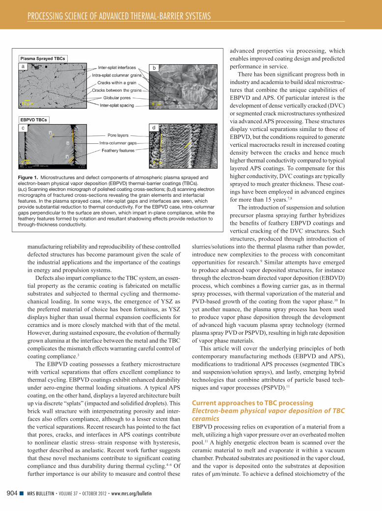
Figure 1. Microstructures and defect components of atmospheric plasma sprayed and
electron-beam physical vapor deposition (EBPVD) thermal-barrier coatings (TBCs).
(a,c) Scanning electron micrograph of polished coating cross-sections; (b,d) scanning electron
micrographs of fractured cross-sections revealing the grain elements and interfacial
features. In the plasma sprayed case, inter-splat gaps and interfaces are seen, which
provide substantial reduction to thermal conductivity. For the EBPVD case, intra-columnar
gaps perpendicular to the surface are shown, which impart in-plane compliance, while the
feathery features formed by rotation and resultant shadowing effects provide reduction to
through-thickness conductivity.
PROCESSING SCIENCE OF ADVANCED THERMAL-BARRIER SYSTEMS
905MRS BULLETIN • VOLUME 37 • OCTOBER 2012 • www.mrs.org/bulletin
zirconia, oxygen is bled into the deposition chamber to com-
pensate for the defi cit caused by dissociation. Rotation of the
parts is mandatory if the substrates or blades need to be coated
on all sides. Due to the formation of the coating from the vapor
phase and combined actions of surface diffusion, shadowing,
and crystallographic growth selection, a columnar microstruc-
ture of the TBC can be achieved, providing a high level of strain
tolerance ( Figure 1c–d ). To ensure continuous growth of the
ceramic coating, cylindrical ingots of the ceramic are bottom-fed
into the crucibles.
Formation of the microstructure of EBPVD TBCs is closely
connected to processing conditions used. 12 Columns and inter-
columnar gaps originate from vapor phase condensation and
macroscopic shadowing caused by the curved column tips,
triggered by rotation of the parts during deposition. Since shad-
owing occurs primarily along the plane of vapor incidence,
columns are signifi cantly wider in the direction parallel to the
rotation axis than perpendicular to it, leading to an anisotropy
of the in-plane compliance with notable consequences to the
strain tolerance of the TBC system.
Globular and elongated spheroid pores are a consequence
of rotation. They are arranged in layers inward from the edge
to the center of the columns nearly parallel to the substrate
surface, more precisely parallel to the individual column tip
at that very location during growth. Each layer represents
one revolution. These features are believed to consist mostly
of closed porosity. Due to the sunset-sunrise situation as the
object rotates perpendicular to the direction of deposition, bent
sub-columns within each layer may be visible, depending on
rotational speed, cutting direction of the cross-section for SEM
with regard to the rotational axis, and thickness of the TBC.
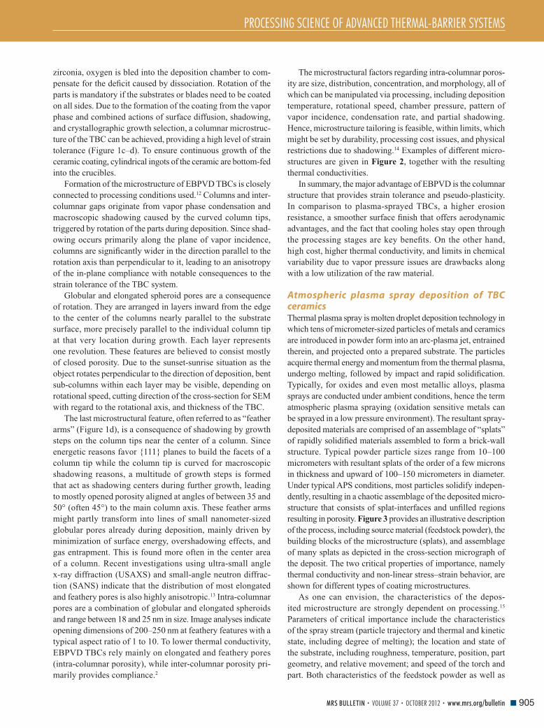
The last microstructural feature, often referred to as “feather
arms” ( Figure 1d ), is a consequence of shadowing by growth
steps on the column tips near the center of a column. Since
energetic reasons favor {111} planes to build the facets of a
column tip while the column tip is curved for macroscopic
shadowing reasons, a multitude of growth steps is formed
that act as shadowing centers during further growth, leading
to mostly opened porosity aligned at angles of between 35 and
50° (often 45°) to the main column axis. These feather arms
might partly transform into lines of small nanometer-sized
globular pores already during deposition, mainly driven by
minimization of surface energy, overshadowing effects, and
gas entrapment. This is found more often in the center area
of a column. Recent investigations using ultra-small angle
x-ray diffraction (USAXS) and small-angle neutron diffrac-
tion (SANS) indicate that the distribution of most elongated
and feathery pores is also highly anisotropic. 13 Intra-columnar
pores are a combination of globular and elongated spheroids
and range between 18 and 25 nm in size. Image analyses indicate
opening dimensions of 200–250 nm at feathery features with a
typical aspect ratio of 1 to 10. To lower thermal conductivity,
EBPVD TBCs rely mainly on elongated and feathery pores
(intra-columnar porosity), while inter-columnar porosity pri-
marily provides compliance. 2
The microstructural factors regarding intra-columnar poros-
ity are size, distribution, concentration, and morphology, all of
which can be manipulated via processing, including deposition
temperature, rotational speed, chamber pressure, pattern of
vapor incidence, condensation rate, and partial shadowing.
Hence, microstructure tailoring is feasible, within limits, which
might be set by durability, processing cost issues, and physical
restrictions due to shadowing. 14 Examples of different micro-
structures are given in Figure 2 , together with the resulting
thermal conductivities.
In summary, the major advantage of EBPVD is the columnar
structure that provides strain tolerance and pseudo-plasticity.
In comparison to plasma-sprayed TBCs, a higher erosion
resistance, a smoother surface fi nish that offers aerodynamic
advantages, and the fact that cooling holes stay open through
the processing stages are key benefi ts. On the other hand,
high cost, higher thermal conductivity, and limits in chemical
variability due to vapor pressure issues are drawbacks along
with a low utilization of the raw material.
Atmospheric plasma spray deposition of TBC ceramics Thermal plasma spray is molten droplet deposition technology in
which tens of micrometer-sized particles of metals and ceramics
are introduced in powder form into an arc-plasma jet, entrained
therein, and projected onto a prepared substrate. The particles
acquire thermal energy and momentum from the thermal plasma,
undergo melting, followed by impact and rapid solidifi cation.
Typically, for oxides and even most metallic alloys, plasma
sprays are conducted under ambient conditions, hence the term
atmospheric plasma spraying (oxidation sensitive metals can
be sprayed in a low pressure environment). The resultant spray-
deposited materials are comprised of an assemblage of “splats”
of rapidly solidifi ed materials assembled to form a brick-wall
structure. Typical powder particle sizes range from 10–100
micrometers with resultant splats of the order of a few microns
in thickness and upward of 100–150 micrometers in diameter.
Under typical APS conditions, most particles solidify indepen-
dently, resulting in a chaotic assemblage of the deposited micro-
structure that consists of splat-interfaces and unfi lled regions
resulting in porosity. Figure 3 provides an illustrative description
of the process, including source material (feedstock powder), the
building blocks of the microstructure (splats), and assemblage
of many splats as depicted in the cross-section micrograph of
the deposit. The two critical properties of importance, namely
thermal conductivity and non-linear stress–strain behavior, are
shown for different types of coating microstructures.
As one can envision, the characteristics of the depos-
ited microstructure are strongly dependent on processing. 15
Parameters of critical importance include the characteristics
of the spray stream (particle trajectory and thermal and kinetic
state, including degree of melting); the location and state of
the substrate, including roughness, temperature, position, part
geometry, and relative movement; and speed of the torch and
part. Both characteristics of the feedstock powder as well as

PROCESSING SCIENCE OF ADVANCED THERMAL-BARRIER SYSTEMS
906 MRS BULLETIN • VOLUME 37 • OCTOBER 2012 • www.mrs.org/bulletin
the attributes of the spray device are of signifi cance. All of
the mentioned processing attributes govern the nature of the
deposit buildup and, as such, both the extrinsic microstructural
character (porosity, interfaces) as well as intrinsic or mate-
rial dependent attributes (grain size, texture, cracking, phase
evolution, and stability). With respect to TBC systems based
on the YSZ polymorph, the critical microstructural elements
include splat and interpass interfaces (the latter is a temporal
effect associated with torch movement), intra-splat cracking
due to relief of very large quenching stresses upon impact and
solidifi cation, and fi nally incompletely fi lled layers resulting
in highly varied porosity. 16
Much progress has been achieved in our ability to char-
acterize the interplay between processing and microstructure
and hence the performances of this complex defect containing
system. Although the processing conditions can affect the
defect quantity and type in a very signifi cant way for YSZ,
there has been specifi c and steady progress not only in mac-
roscopic quantifi cation of the structure-property relationship
(e.g., porosity-thermal conductivity relations) but also in the
underlying fundamentals in terms of the generation of the defect
type and their characteristics. 17 This is particularly signifi cant
for monitoring and controlling coating compliance, which in
recent years has been attributed to the unique nonlinear/anelastic
response of the porous ceramic coating on metallic substrates. 3 , 18
An illustrative example of the link between processing and
porosity properties is provided in the plots in Figure 3d–e , where
thermal conductivity and compliance are described for different
microstructures. These developments have not only enhanced
the applicability of YSZ TBC systems, but have also paved the
way for expanded opportunities for other oxide systems.
In recent years, much of the scientifi c and technological
efforts have focused on process control to achieve reliable
manufacturing of TBC coatings. TBCs are fabricated by small
to large factories all over the world to specifi cations defi ned by
the engine manufacturer. As these spray factories are entitled
to use any available (approved) spray device and powder, the
specifi cations tend to be rather wide to accommodate micro-
structural variation. This has, to some extent, resulted in design
engineers reducing their reliance on the coating for reliable
performance and focusing more on life extension of the under-
lying superalloy components. However, as the engine inlet tem-
peratures increase, the need for reliable and controlled coatings
is becoming increasingly critical. As such, advancements in
process science have been sought to develop methodologies
not only for process control, but also effective materials science
descriptions for microstructural control.
Segmented cracked TBCs via advanced APS strategies Both APS and EBPVD coatings, which are now used in main-
stream TBC manufacturing, offer benefi ts in terms of both
Figure 2. A schematic of electron-beam physical vapor deposition (EBPVD) processing is shown, where the orange and green represent
two vapor clouds of different chemistry that can be mixed on the airfoil. (a–d) Electron micrographs showing cross-sections of the column
tips found in EBPVD coatings, demonstrate the variability of microstructure achievable by varying important EBPVD process parameters
such as substrate temperature and rotational speed, including variation in column diameter, porosity, and width of inter-columnar gaps.
The plot shows their corresponding thermal conductivity values. 2

PROCESSING SCIENCE OF ADVANCED THERMAL-BARRIER SYSTEMS
907MRS BULLETIN • VOLUME 37 • OCTOBER 2012 • www.mrs.org/bulletin
compliance and conductivity due to their defected structure.
Typical APS coatings offer lower conductivity, but EBPVD
coatings provide for better compliance and erosion resistance.
As outlined earlier, there is signifi cant interest to incorporate
the benefi ts of EBPVD into APS coatings, particularly for large
component TBC applications in power systems. This has led
to both industrial and academic research on segmented or
vertically cracked ceramic coatings and their successful imple-
mentation in gas turbines. 7 , 8 , 20 , 21
Plasma sprayed zirconia splats undergo extremely rapid
quenching (10 8 K s –1 ) as they impact a substrate or the surface
of already deposited layers, spread into sheets of a few μ m thick-
ness, and are cooled down predominantly by thermal conduction
to the underlying solid body. As a result, if one observes a single
ceramic splat formed on a fl at metal substrate, an intricate net-
work of microcracks can be seen ( Figure 3b ). The patterns and
the principle behind the formation of these cracks are similar to
mud cracking or crazing on some porcelain pieces, where the
shrinkage of the surface layer is restricted by the underlying
massive body, resulting in large lateral tensile stresses and con-
sequent cracking during cooling. Since the coeffi cient of thermal
expansion of YSZ is approximately 10 –5 K –1 , and the temperature
drop Δ T that plasma sprayed splats undergo is more than 2000 K,
the amount of strain that must be incorporated is approximately
2 × 10 –2 , which is an order of magnitude larger than the failure
strain of most ceramics, including zirconia.
As a result, APS ceramic coatings usually contain a large
number of microcracks. When the deposition temperature is
raised signifi cantly, an interesting tendency has been observed
to transition from splat level microcracking to large macro-
scale cracking (i.e., so-called segmentation cracks or dense
vertical cracks). Figure 4 provides an illustrative description
of the phenomenon indicating the role of substrate temperature
on the segmentation crack density. 20 It has been shown that
the density of segmentation cracks increases at the expense of
micropores as the substrate/deposition temperature increases. 21
This transition is related to both the improvement of wet-
ting between overlaid splats at high deposition temperatures
and the reduction of the temperature drop Δ T . As the wetting
among several splats improves and multiple splats are con-
nected at high temperature, they start to behave more or less
as a larger single body. There is also evidence of columnar
grains grown across multiple splats when observations are
made on fractured cross-sections. As a result, cracks between
thicker masses of zirconia are formed associated with more
macroscopic temperature variations experienced during APS.
Recent experiments to detect acoustic emission during APS
to some extent support this hypothesis, but further investiga-
tion is needed. 22 Signifi cant improvement in terms of thermal
cycle life has been reported for such vertically cracked TBCs,
and this technology has been used in industry for more than
a decade.
Despite the industrial acceptance of these techniques, sev-
eral fundamental issues remain, such as what optimal crack
density is needed to achieve optimum performance as a TBC.
Furthermore, thermal conductivity is somewhat sacrifi ced, as
there is greater vertical connection of splats as compared to
TBCs sprayed in a conventional manner, where signifi cant
Figure 3. Illustrative description of atmospheric plasma spray deposition process for thermal-barrier coatings in which a ceramic feedstock
(gray dots) is carried to the substrate by a plasma spray. Electron micrographs show (a) the feedstock powder, (b) an individual component
of the coating assembly (splat), and (c) a polished cross-section of an aggregated coating. On the right are (d) thermal conductivities of
three different coatings with different pore/interface content, along with (e) non-linear stress–strain relations as obtained from curvature
measurements. Detailed description of the parametric effects can be found in References 4 , 18 , and 19 .

PROCESSING SCIENCE OF ADVANCED THERMAL-BARRIER SYSTEMS
908 MRS BULLETIN • VOLUME 37 • OCTOBER 2012 • www.mrs.org/bulletin
portions of the lamellar interfaces are not bonded. 23 This results
in a signifi cantly thicker TBC being needed to impart similar
heat resistance.
Suspension and solution plasma spraying of ceramics Thermal spray processes usually involve the injection of a powder
feedstock into a fl ame or a plasma jet. In the case of the conven-
tional APS process, the powder particles must have a diameter
in the range of 10–100 μ m in order to be fl owable (favored by
smaller particles) and also capable of impact deposition (requires
inertial mass). This limitation in the feedstock particle size leads
to limitations in terms of expanding process capabilities. With
APS, it is diffi cult to obtain nanostructured coatings with a very
fi ne microstructure and/or to manufacture very thin coatings
(below approx. 10 μ m in thickness), as at least several lamellae
piled up on each other are necessary to form a coating.
Suspensions and solutions have long been considered as
alternative feedstock for plasma spray. 9 , 24 , 25 This area received
much more attention in recent years through the desire to both
use nanostructured materials as well as to fabricate nano-
structured coatings. In this approach, submicron particles are
agglomerated within a liquid suspension to allow their intro-
duction into high pressure thermal plasma jets. Referred to as
suspension plasma spraying (SPS), this relatively novel process
is very promising for the manufacture of nanostructured coat-
ings for a large range of applications.
The use of such suspensions or solutions in the case of TBC
deposition leads to the generation of hybrid microstructures
that combine the low conductivity of APS TBCs resulting
from through-thickness layering with the ability to produce
vertical separations (segmented cracks) imparting in-plane
compliance. 26 , 27 In some respects, this technique combines the
advantages of traditional APS, segmented crack structures, and
EBPVD attributes, and overcomes some of the limitations of
segmented crack TBCs.
To produce SPS coatings, fi ne particles of the oxide materials
are dispersed in a solvent such as ethanol with a solid fraction
commonly in the range of 5–30 wt%, and the formulated suspen-
sion is directly injected into a typical APS thermal plasma jet
( Figure 5 ). Liquid injection can be realized as a coherent stream
or as atomized droplets. 26 When entering the plasma jet, the liquid
is subjected to fragmentation due to the plasma jet shear effects,
yielding even smaller suspension droplets. 27 The solvent is
rapidly vaporized, and the particles located in a single droplet
form an agglomerate. The obtained solid agglomerates are
accelerated and melted in the plasma jet, transforming into
ceramic molten droplets, and eventually impacted onto the
substrate surface. The deposited splats have very small
dimensions (diameters from 0.2–6 μ m and thicknesses of
20–300 nm 28 ) compared to typical APS splats having thicknesses
of about 2–5 μ m. As a result, SPS coatings have an increased
number of lamellae and interfaces and present signifi cantly
fi ner microstructures, resulting in coatings with signifi cantly
lower thermal conductivities than conventional APS coatings. 29
The processing conditions for SPS are drastically different
than those of APS in two ways: First, the powder carrier is no
longer a gas but a liquid whose interaction with hot gases is
Figure 4. Metallographically prepared cross-sections of (a) traditional (non-segmented) and (b) highly segmented thermal-barrier coatings
(TBCs) produced at low and high substrate temperatures, respectively, with enlarged scanning electron microscopy images obtained
from fractured sections of the coatings. On the right are plots of thermal cycle life of TBCs tested at 1100 and 1200°C as a function of
segmentation crack density. C1 to C4 correspond to different plasma spray conditions with increasingly higher substrate temperatures
during spraying. 20
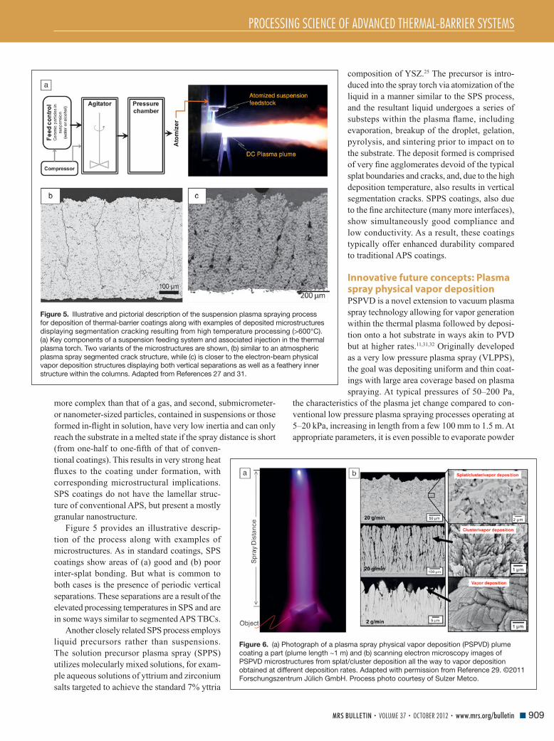
PROCESSING SCIENCE OF ADVANCED THERMAL-BARRIER SYSTEMS
909MRS BULLETIN • VOLUME 37 • OCTOBER 2012 • www.mrs.org/bulletin
more complex than that of a gas, and second, submicrometer-
or nanometer-sized particles, contained in suspensions or those
formed in-fl ight in solution, have very low inertia and can only
reach the substrate in a melted state if the spray distance is short
(from one-half to one-fi fth of that of conven-
tional coatings). This results in very strong heat
fl uxes to the coating under formation, with
corresponding microstructural implications.
SPS coatings do not have the lamellar struc-
ture of conventional APS, but present a mostly
granular nanostructure.
Figure 5 provides an illustrative descrip-
tion of the process along with examples of
microstructures. As in standard coatings, SPS
coatings show areas of (a) good and (b) poor
inter-splat bonding. But what is common to
both cases is the presence of periodic vertical
separations. These separations are a result of the
elevated processing temperatures in SPS and are
in some ways similar to segmented APS TBCs.
Another closely related SPS process employs
liquid precursors rather than suspensions.
The solution precursor plasma spray (SPPS)
utilizes molecularly mixed solutions, for exam-
ple aqueous solutions of yttrium and zirconium
salts targeted to achieve the standard 7% yttria
composition of YSZ. 25 The precursor is intro-
duced into the spray torch via atomization of the
liquid in a manner similar to the SPS process,
and the resultant liquid undergoes a series of
substeps within the plasma fl ame, including
evaporation, breakup of the droplet, gelation,
pyrolysis, and sintering prior to impact on to
the substrate. The deposit formed is comprised
of very fi ne agglomerates devoid of the typical
splat boundaries and cracks, and, due to the high
deposition temperature, also results in vertical
segmentation cracks. SPPS coatings, also due
to the fi ne architecture (many more interfaces),
show simultaneously good compliance and
low conductivity. As a result, these coatings
typically offer enhanced durability compared
to traditional APS coatings.
Innovative future concepts: Plasma spray physical vapor deposition PSPVD is a novel extension to vacuum plasma
spray technology allowing for vapor generation
within the thermal plasma followed by deposi-
tion onto a hot substrate in ways akin to PVD
but at higher rates. 11 , 31 , 32 Originally developed
as a very low pressure plasma spray (VLPPS),
the goal was depositing uniform and thin coat-
ings with large area coverage based on plasma
spraying. At typical pressures of 50–200 Pa,
the characteristics of the plasma jet change compared to con-
ventional low pressure plasma spraying processes operating at
5–20 kPa, increasing in length from a few 100 mm to 1.5 m. At
appropriate parameters, it is even possible to evaporate powder
Figure 5. Illustrative and pictorial description of the suspension plasma spraying process
for deposition of thermal-barrier coatings along with examples of deposited microstructures
displaying segmentation cracking resulting from high temperature processing (>600°C).
(a) Key components of a suspension feeding system and associated injection in the thermal
plasma torch. Two variants of the microstructures are shown, (b) similar to an atmospheric
plasma spray segmented crack structure, while (c) is closer to the electron-beam physical
vapor deposition structures displaying both vertical separations as well as a feathery inner
structure within the columns. Adapted from References 27 and 31 .
Figure 6. (a) Photograph of a plasma spray physical vapor deposition (PSPVD) plume
coating a part (plume length ∼ 1 m) and (b) scanning electron microscopy images of
PSPVD microstructures from splat/cluster deposition all the way to vapor deposition
obtained at different deposition rates. Adapted with permission from Reference 29 . ©2011
Forschungszentrum Jülich GmbH. Process photo courtesy of Sulzer Metco.

PROCESSING SCIENCE OF ADVANCED THERMAL-BARRIER SYSTEMS
910 MRS BULLETIN • VOLUME 37 • OCTOBER 2012 • www.mrs.org/bulletin
feedstock material, achieving advanced microstructures and
non-line of sight deposition (e.g., for TBCs). Thin and dense
ceramic coatings as well as columnar-structured strain-tolerant
coatings with low thermal conductivity can be achieved. 5
Under certain process conditions, it is possible to use VLPPS
to obtain structures very similar to that of EBPVD, hence these
conditions are termed PSPVD. Figure 6 shows examples of
microstructures obtained from the VLPPS process at different
deposition rates ranging from splat/cluster deposition all the
way to vapor deposition. PSPVD has the advantage of coating
non-line of sight objects, such as complex shaped vane doublets
at a relatively higher rate. The process is currently being inves-
tigated by turbine companies for potential commercialization.
Summary and concluding remarks The integration of thermal-barrier coatings (TBCs) into modern
propulsion and energy-generating turbine systems has allowed
both performance enhancement and life extension of advanced
superalloy components. Their widespread use has created a
large industrial manufacturing base for advanced ceramic
deposition technologies, such as plasma spray and EBPVD.
Advanced TBCs are now moving from life extension to prime
reliance (i.e., they are essential to component life and engine
operation), requiring insertion of process science and control in
manufacturing. Given the complexity in terms of structure,
defects, and layering, the interplay between scientifi c research
and technology will continue to evolve. To some extent, the
ease of TBC processing is enabled due to the utilization of
YSZ. Both yttria and zirconia have similar vapor pressures,
melting points, and thermophysical characteristics, and as such
chemical complications from rapid heating, melting, and evap-
oration are not signifi cant. However, industry is moving toward
more complex compositions (e.g., multicomponent stabilization
based Y, Yb, and Gd), as well as pyrochlore structures based
on zirconates (La 2 Zr 2 O 7 , Gd 2 Zr 2 O 7 ) to meet new performance
requirements such as erosion resistance, molten glass attack
(CMAS), as well as increased heat fl ux. 33 – 35
An additional issue for consideration is the stability of the
as-deposited defected microstructure and their crystal phases
during sustained thermal exposure. In the case of YSZ, at
temperatures above 1000°C, the porosity and splat interfaces
tend to sinter, causing a loss of compliance and an increase in
conductivity. The extent of sintering is microstructure depen-
dent and controlled via processing parameters. 36 Similarly, both
APS and EBPVD YSZ coatings are comprised of a metastable
tetragonal prime (t’) structure, which is generally stable up to
1200°C. Under sustained exposure above 1200°C, the t’ phase is
susceptible to decomposition into cubic and tetragonal forms,
with the latter ultimately transforming into monoclinic upon cool-
ing. 37 The t’ phase is also known to be of signifi cantly higher tough-
ness than other phases due to ferroelastic switching events, which
not only depend on composition but also on metastability. 38
Thus, emergence of new compositions is closely tied to process-
related microstructural and phase attributes. It is clear that
future development of TBCs will involve integration among
processing science, phase/microstructure control, and linkage
to performance. Research is under way in all of these areas,
driven by the need for reliable multifunctional coating systems.
Acknowledgments We are grateful to Dr. Gopal Dwivedi of Stony Brook University
for his assistance in integrating the fi gures for this article.
References 1. A. Kulkarni , Z. Wang , T. Nakamura , S. Sampath , A. Goland , H. Herman , J. Allen , J. Ilavsky , G. Long , J. Frahm , R.W. Steinbrech , Acta Mater. 51 , 2457 ( 2003 ). 2. A. Flores Renteria , B. Saruhan , U. Schulz , H.-J. Raetzer-Scheibe , J. Haug , A. Wiedenmann , Surf. Coat. Technol. 201 , 2611 ( 2006 ). 3. A.G. Evans , D.R. Mumm , J.W. Hutchinson , G.H. Meier , F.S. Pettit , Prog. Mater. Sci. 46 ( 5 ) 505 ( 2001 ). 4. Y. Liu , T. Nakamura , G. Dwivedi , A. Valarezo , S. Sampath , J. Am. Ceram. Soc. 91 ( 12 ), 4036 ( 2008 ). 5. Y. Liu , T. Nakamura , V. Srinivasan , A. Vaidya , A. Gouldstone , S. Sampath , Acta Mater. 55 , 4667 ( 2007 ). 6. C.A. Johnson , J.A. Ruud , R. Bruce , D. Wortman , Surf. Coat. Technol. 108 , 80 ( 1998 ). 7. T.A. Taylor , US Patent 5, 073, 433 ( 1989 ). 8. D.M. Gray , Y.C. Lau , C.A. Johnson , M.P. Boron , W.A. Nelson , US Patent 5,830,586 ( 1996 ). 9. P. Fauchais , G. Montavon , J. Therm. Spray Technol. 19 ( 1–2 ), 226 ( 2010 ). 10. D.D. Hass , H.N.G. Wadley , US Patent Appl. 2008/0131611 A1 ( 2008 ). 11. K. Von Niessen , M. Gindrat , J. Therm. Spray Technol. 20 ( 4 ), 736 ( 2011 ). 12. U. Schulz , B. Saruhan , K. Fritscher , C. Leyens , Int. J. Appl. Ceram. Technol. 1 , 302 ( 2004 ). 13. A. Flores Renteria , B. Saruhan , J. Ilavsky , A.J. Allen , Surf. Coat. Tech. 201 ( 8 ) 4781 ( 2007 ). 14. U. Schulz , S.G. Terry , C.G. Levi , Mater. Sci. Eng. A 360 , 319 ( 2003 ). 15. A. Vaidya , V. Srinivasan , T. Streibl , M. Friis , W. Chi , S. Sampath , Mater. Sci. Eng., A 497 , 239 ( 2008 ). 16. S. Kuroda , T.W. Clyne , Thin Solid Films 200 ( 1 ), 49 ( 1991 ). 17. T. Nakamura , Y. Liu , Int. J. Solids Struct. 44 ( 6 ), 1990 ( 2007 ). 18. W. Chi , S. Sampath , H. Wang , J. Am. Ceram. Soc. 91 ( 8 ), 2636 ( 2008 ). 19. G. Dwivedi , T. Nakamura , S. Sampath , J. Am. Ceram. Soc. 94 , 104 ( 2011 ). 20. H.B. Guo , H. Murakami , S. Kuroda , Mater. Trans. 47 ( 42 ), 308 ( 2006 ). 21. H.B. Guo , R. Vaßen , D. Stöver , Surf. Coat. Technol. 186 ( 3 ), 353 ( 2004 ). 22. K. Ito , H. Kuriki , M. Watanabe , S. Kuroda , M. Enoki , Mater. Trans. 53 , 671 ( 2012 ). 23. A. Kulkarni , A. Goland , H. Herman , A. Allen , J. Ilavsky , G. Long , C. Johnson , J. Ruud , J. Am. Ceram. Soc. 87 ( 7 ), 1294 ( 2004 ). 24. J. Karthikeyan , C.C. Berndt , J. Tikkanen , S. Reddy , H. Herman , Mater. Sci. Eng., A 238 ( 2 ), 275 ( 1997 ). 25. T. Bhatia , A. Ozturk , L. Xie , E. Jordan , B. Cetegen , M. Gell , X. Ma , N. Padture , J. Mater. Res. 17 , 2363 ( 2002 ). 26. R. Rampon , C. Filiatre , G. Bertrand , J. Therm. Spray Technol. 17 ( 1 ), 105 ( 2008 ). 27. C. Delbos , J. Fazilleau , V. Rat , J.F. Coudert , P. Fauchais , B. Pateyron , Plasma Chem. Plasma Process. 26 ( 4 ), 393 ( 2006 ). 28. H. Kassner , R. Siegert , D. Hathiramani , R. Vassen , D. Stoever , J. Therm. Spray Technol. 17 ( 1 ), 115 ( 2008 ). 29. H. Kaßner , A. Stuke , M. Rödig , R. Vaßen , D. Stöver , Ceramic Engineering and Science Proceedings 29 ( 4 ) 147 ( 2009 ). 30. A. Guignard , G. Mauer , R. Vaßen , D. Stöver , J. Therm. Spray Technol. 21 , 416 ( 2012 ). 31. A. Guignard , doctoral thesis , Ruhr University , Bochum, Germany ( 2012 ). 32. A. Hospach , G. Mauer , R. Vassen , D. Stover , J. Therm. Spray Technol. 20 ( 1–2 ), 116 ( 2011 ). 33. D. Zhu , R. Miller , Int. J. Appl. Ceram. Technol. 1 , 86 ( 2004 ). 34. R. Vassen , X. Cao , F. Tietz , D. Basu , D. Stöver , J. Am. Ceram. Soc. 83 ( 8 ), 2023 ( 2000 ). 35. M. Jarligo , D.E. Mack , R. Vassen , D. Stöver , J. Therm. Spray Technol. 18 ( 2 ), 187 ( 2009 ). 36. Y. Tan , J. Longtin , S. Sampath , H. Wang , J. Am. Ceram. Soc. 92 ( 3 ), 710 ( 2009 ). 37. R.A. Miller , J.L. Smialek , R.G. Garilick , in Science and Technology of Zirconia I , A.H. Heuer , L.W. Hobbs , Eds. ( American Ceramic Society , Columbus, OH , 1981 ), p. 241 . 38. C. Mercer , J.R. Williams , D.R. Clarke , A.G. Evans , Proc. R. Soc. 463 ( 2081 ), 1393 ( 2007 ).
911MRS BULLETIN • VOLUME 37 • OCTOBER 2012 • www.mrs.org/bulletin© 2012 Materials Research Society
Introduction Testing thermal-barrier coating (TBC) systems and evaluating
their performance in service presents major challenges. First
and foremost, the conditions under which they operate are often
extremely harsh, combining high temperatures, steep tempera-
ture gradients, fast temperature transients, high pressures,
and additional mechanical loading, as well as oxidative and
corrosive environments. These are diffi cult to reproduce in the
laboratory. The coating system also changes with time and tem-
perature as interdiffusion occurs, microstructures evolve, and
the properties of the constituent multilayer materials change.
For instance, the oxide topcoat sinters, 1,12 increasing both its ther-
mal conductivity and elastic modulus, but the rate of sintering
depends on its purity. Furthermore, the properties that need to
be evaluated are rarely those of the constituent bulk materials
themselves. For instance, while the intrinsic fracture tough-
ness of the ceramic topcoat—typically made of 7 wt% yttria-
stabilized zirconia (7YSZ)—is important, it is the toughness
that a delamination crack experiences as it extends in or near the
interface with the thermally grown oxide (TGO) that directly
infl uences the lifetime under thermal cycling conditions. As
coatings become prime-reliant, meaning that they can be imple-
mented into the design of the engine with reliable performance
criteria, it is also essential to develop sensors and nondestructive
evaluation methods to monitor TBC temperatures, the extent
of sub-critical delamination in service, as well as identifying
manufacturing fl aws, while also creating an artifi cial intelli-
gence supervisory system that can be implemented in the fi eld
to provide feedback to the manufacturing and design sectors
for product improvement. Several sensor approaches are being
explored, including infrared imaging, Raman spectroscopy,
thermography, impedance spectroscopy, acoustic emission,
and luminescence sensing. 2–7
Mechanical properties One of the fundamental problems in discussing and evaluating
the mechanical properties of coatings is establishing what the
appropriate value of a particular property should be and at what
microstructural scale it should be determined. This is espe-
cially true of the oxide topcoat since considerable variability
and uncertainty arise from the porous nature of the coating as
well as its anisotropy and microstructural evolution at elevated
temperatures. For simple properties, such as the overall ther-
mal expansion mismatch stresses on thermal cycling and the
available elastic strain energy release rate, the macroscopic
biaxial Young’s modulus, such as determined by a macroscopic
mechanical test, is generally adequate, recognizing that it can
be expected to be different under tension than compression.
In contrast, the local modulus obtained by nanoindentation,
for instance, pertains to the modulus of the intrinsic material
Testing and evaluation of thermal-barrier coatings Robert Vaßen , Yutaka Kagawa , Ramesh Subramanian , Paul Zombo , and Dongming Zhu
Thermal-barrier coatings are complex systems with properties that largely depend on
their specifi c microstructure. Their properties change during operation, typically leading
to degradation. A further diffi culty arises from the fact that this degradation also depends
on specifi c loading conditions that can be rather complex. Different laboratory setups are
described that simulate, at least partially, the actual loading conditions. In addition, sensing
and nondestructive methods are described that are targeted toward reliable operation of a
gas-turbine engine with thermal-barrier coated components.
Robert Vaßen, Institute of Energy and Climate Research , Forschungszentrum Jülich GmbH , Germany ; [email protected] Yutaka Kagawa, Research Center for Advanced Science and Technology , The University of Tokyo , Japan ; [email protected] Ramesh Subramanian, Siemens Energy Inc. , Orlando , FL ; [email protected] Paul Zombo, Engine and Component Diagnostics , Siemens Energy Inc. , Orlando , FL ; [email protected] Dongming Zhu, Durability and Protective Coatings Branch , Structures and Materials Division , NASA Glenn Research Center , Cleveland , OH ; [email protected] DOI: 10.1557/mrs.2012.235
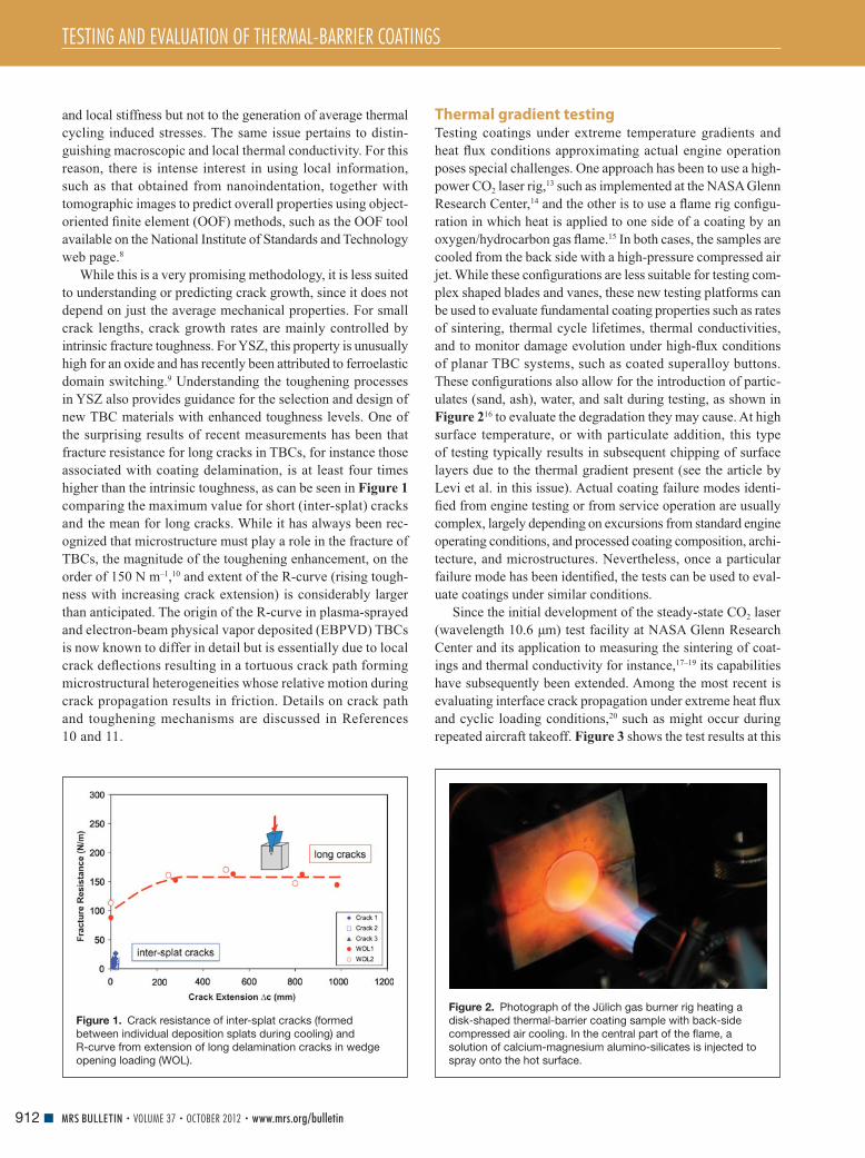
TESTING AND EVALUATION OF THERMAL-BARRIER COATINGS
912 MRS BULLETIN • VOLUME 37 • OCTOBER 2012 • www.mrs.org/bulletin
and local stiffness but not to the generation of average thermal
cycling induced stresses. The same issue pertains to distin-
guishing macroscopic and local thermal conductivity. For this
reason, there is intense interest in using local information,
such as that obtained from nanoindentation, together with
tomographic images to predict overall properties using object-
oriented fi nite element (OOF) methods, such as the OOF tool
available on the National Institute of Standards and Technology
web page. 8
While this is a very promising methodology, it is less suited
to understanding or predicting crack growth, since it does not
depend on just the average mechanical properties. For small
crack lengths, crack growth rates are mainly controlled by
intrinsic fracture toughness. For YSZ, this property is unusually
high for an oxide and has recently been attributed to ferroelastic
domain switching. 9 Understanding the toughening processes
in YSZ also provides guidance for the selection and design of
new TBC materials with enhanced toughness levels. One of
the surprising results of recent measurements has been that
fracture resistance for long cracks in TBCs, for instance those
associated with coating delamination, is at least four times
higher than the intrinsic toughness, as can be seen in Figure 1
comparing the maximum value for short (inter-splat) cracks
and the mean for long cracks. While it has always been rec-
ognized that microstructure must play a role in the fracture of
TBCs, the magnitude of the toughening enhancement, on the
order of 150 N m –1 , 10 and extent of the R-curve (rising tough-
ness with increasing crack extension) is considerably larger
than anticipated. The origin of the R-curve in plasma-sprayed
and electron-beam physical vapor deposited (EBPVD) TBCs
is now known to differ in detail but is essentially due to local
crack defl ections resulting in a tortuous crack path forming
microstructural heterogeneities whose relative motion during
crack propagation results in friction. Details on crack path
and toughening mechanisms are discussed in References
10 and 11.
Thermal gradient testing Testing coatings under extreme temperature gradients and
heat fl ux conditions approximating actual engine operation
poses special challenges. One approach has been to use a high-
power CO 2 laser rig, 13 such as implemented at the NASA Glenn
Research Center, 14 and the other is to use a fl ame rig confi gu-
ration in which heat is applied to one side of a coating by an
oxygen/hydrocarbon gas fl ame. 15 In both cases, the samples are
cooled from the back side with a high-pressure compressed air
jet. While these confi gurations are less suitable for testing com-
plex shaped blades and vanes, these new testing platforms can
be used to evaluate fundamental coating properties such as rates
of sintering, thermal cycle lifetimes, thermal conductivities,
and to monitor damage evolution under high-fl ux conditions
of planar TBC systems, such as coated superalloy buttons.
These confi gurations also allow for the introduction of partic-
ulates (sand, ash), water, and salt during testing, as shown in
Figure 2 16 to evaluate the degradation they may cause. At high
surface temperature, or with particulate addition, this type
of testing typically results in subsequent chipping of surface
layers due to the thermal gradient present (see the article by
Levi et al. in this issue). Actual coating failure modes identi-
fi ed from engine testing or from service operation are usually
complex, largely depending on excursions from standard engine
operating conditions, and processed coating composition, archi-
tecture, and microstructures. Nevertheless, once a particular
failure mode has been identifi ed, the tests can be used to eval-
uate coatings under similar conditions.
Since the initial development of the steady-state CO 2 laser
(wavelength 10.6 μ m) test facility at NASA Glenn Research
Center and its application to measuring the sintering of coat-
ings and thermal conductivity for instance, 17 – 19 its capabilities
have subsequently been extended. Among the most recent is
evaluating interface crack propagation under extreme heat fl ux
and cyclic loading conditions, 20 such as might occur during
repeated aircraft takeoff. Figure 3 shows the test results at this
Figure 1. Crack resistance of inter-splat cracks (formed
between individual deposition splats during cooling) and
R-curve from extension of long delamination cracks in wedge
opening loading (WOL).
Figure 2. Photograph of the Jülich gas burner rig heating a
disk-shaped thermal-barrier coating sample with back-side
compressed air cooling. In the central part of the fl ame, a
solution of calcium-magnesium alumino-silicates is injected to
spray onto the hot surface.

TESTING AND EVALUATION OF THERMAL-BARRIER COATINGS
913MRS BULLETIN • VOLUME 37 • OCTOBER 2012 • www.mrs.org/bulletin
facility of a 127- μ m-thick, precracked TBC specimen, with the
crack introduced at the TBC/bond-coat interface. The initial
ceramic surface temperature was set at approximately 1287°C
and 20-min heating/cooling cycles with 60–100 W cm –2 heat
fl ux were applied. The coating surface temperature increased
continuously as the crack propagated, whereas the metal back-
side temperature remained relatively constant. The apparent
coating thermal conductivity, calculated from the known laser
heat fl ux, decreased as the delamination crack grew until the
test was interrupted by spallation of the coating after about
200 cycles. The crack propagation process was also monitored
independently by a high sensitivity video camera for calibrating
the crack propagation with cycles. From these data, the crack
propagation rate ( da/dN) and the laser thermal transient stress
associated stress intensity factor amplitude ( Δ K ) (the crack
propagation driving force on the coating) for the plasma sprayed
7–8YSZ were also determined. 20 The results show slower
thermal fatigue crack propagation rates compared to monolithic
ceramics, indicative of additional R-curve toughening effects
due to the roughness and plasticity at or near the ceramic/metal
interface.
Thermomechanical fatigue As with other high-temperature materials, including superal-
loys, thermomechanical fatigue (TMF) can adversely infl uence
coating durability. 21 – 24 The origin of TMF is creep and plastic
deformation in each of the component layers in the TBC system
driven by the coeffi cient of thermal expansion (CTE) mismatch,
especially the CTE mismatch between the bond coat, the super-
alloy, and the topcoat under thermal gradient conditions, as well
as mechanical loads, such as centrifugal force. Testing under
TMF conditions is essential, but the wide variety of possible
in-phase mechanical and temperature loadings and out-of-phase
loading conditions as well as realistic thermal gradient conditions
makes this a demanding materials engineering task that is only
now being addressed. Even so, there have been surprises. One
is that contrary to initial expectation, compressive deformation
is the major form of damage in strain-controlled in-phase and
stress-controlled out-of-phase modes. 25 Another is that cracks
can nucleate in the bond coat at high-temperatures and propa-
gate into the superalloy.
Figure 4 illustrates characteristic damage accumulation
behavior in EBPVD TBC systems in an in-phase stress-
controlled TMF test mode. 26 , 27 The temperature of the substrate
is kept at a constant 1000°C, while the TBC surface is heated
to 1150°C and cooled again over 960s cycles. An uniaxial tensile
load of 1.8 kN (60 MPa) is applied to the specimen while the TBC
surface is heated. Evolution of strain with time and numbers
of loading cycles under in-phase TMF test conditions are
consistent with the creep behavior of superalloys ( Figure 4a ).
Ratcheting behavior, 27 where the materials are left permanently
deformed after each cycle, is superimposed on the creep behav-
ior, as illustrated in Figure 4b . This behavior is consistent with
most of the applied load being supported by the superalloy
substrate. However, the creep behavior of the EBPVD TBC
layer is interesting: at 1150°C, the layer can deform up to about
8% tensile strain without evidence of visible cracking. 28 With
increasing tensile creep strain, cracking of the TBC layer initiates,
and, ultimately, multiple fragmentation occurs, as seen in
Figure 4c–d . It is found that the cracks in the TBC layer do not
propagate through the entire thickness, and the crack spacing
of the TBC layer ( Figure 4d ) is much smaller than that pre-
dicted using continuum mechanics. 27 In addition, TMF tests on
samples with a center-hole clearly demonstrate that cracking
is related to tensile stress/strain concentrations. 27 Following
cracking of the TBC layer, void formation in the bond coat
below the cracks can occur, and new oxide forms in the exposed
alloy. The width of the cracks in the TBC layer typically has a
wide distribution, and the cracks below wider TBC layer cracks
propagate deeper into the bond-coat layer ( Figure 4c and 4f ).
The evidence suggests that there is a sequence of cracking in the
TBC oxide. After cracking of the TBC, the life of the system is
similar to that of the bare superalloy. Another form of damage is
large area delamination where the bond coat and superalloy are
locally exposed to higher temperatures ( Figure 4g ). Anisotropic
growth and stress distribution in the TGO layer ( Figure 4h–i )
are also observed and analyzed. 25 , 29
Sensing and non-destructive evaluation Luminescence sensing Concurrent with developments in testing the mechanical prop-
erties of TBC systems, there have been explorations of new
sensing approaches. For instance, as the temperatures at the
TBC surface and at the TGO are critical parameters, there has
been an emphasis on non-contact methods of measuring tem-
perature at these locations. One method that has shown partic-
ular promise is luminescence sensing based on the dependence
of photoluminescence lifetime on temperature. Luminescence
is also used to monitor delamination by detecting the interface
Figure 3. Laser heat fl ux thermal gradient cyclic test results
of a 127- μ m-thick, precracked thermal-barrier coating
specimen subject to 20 min heating and 4 min cooling thermal
cycling. The initial circular crack was 2 mm in diameter. The
effective thermal conductivity clearly correlates with the crack
propagation until the coating spalled after 200 cycles.

TESTING AND EVALUATION OF THERMAL-BARRIER COATINGS
914 MRS BULLETIN • VOLUME 37 • OCTOBER 2012 • www.mrs.org/bulletin
temperature changes and interface luminescence refl ectivity. 30 – 33
In this method, luminescent rare-earth ions are incorporated into
the crystal structure of the YSZ coating during deposition of the
EBPVD coating so that they are localized, for instance, at the
ceramic topcoat/TGO interface and then again at the topcoat
surface. During high temperature testing, they are stimulated
by a pulsed laser, and the decay of the excited luminescence
is monitored. In addition to being a non-contact method, the
rare-earth dopant can also be localized to a smaller depth than the
optical penetration depth in optical pyrometry, giving superior
depth resolution.
This temperature sensing methodology has recently been
demonstrated using EBPVD 7YSZ TBCs 30 , 33 , 34 with an inte-
grated luminescence sensing layer composed of europium
doped YSZ at the TBC/bond-coat interface. The experimental
setup is illustrated in Figure 5 a. 30 A solid-state frequency dou-
bled YAG:Nd laser emitting at 532 nm illuminates the center of
the coating surface, while the high heat fl ux CO 2 laser is used
for heating the specimens under large thermal gradients. A sap-
phire light pipe is positioned to collect the excited luminescence
signal during the testing. Figure 5b shows the luminescence
sensor measured real-time interface temperature under various
heat fl ux conditions, demonstrating the ability to collect lumi-
nescence from a thin embedded sensor layer in TBC systems
under high temperature thermal gradients.
Infrared imaging The key to extending the use of TBCs is assessing damage, espe-
cially sub-critical coating delamination, prior to coating failure.
In particular, early detection of TBC damage also enables a part
to be replaced and, possibly, repaired. The majority of non-
destructive methods for this type of monitoring utilize spectral
variations in the optical properties of YSZ. For instance, at
10.6 μ m, the wavelength of CO 2 lasers, YSZ is heavily absorb-
ing, but it is translucent in the visible and near infrared (IR).
One approach is to image local separations between the coating
and alloy based on variations in refl ectivity of thermal waves
launched by pulse heating of the coating surface. The larger
effusivity at the delamination than at the interface between the
TBC and the underlying alloy locally causes a greater thermal
refl ectivity and hence higher image contrast, enabling an image
to be formed of large delaminations. In the visible, YSZ is
Figure 4. Examples of typical behavior and damage in an electron-beam physical vapor deposited thermal-barrier coating (TBC) system
during in-phase thermomechanical fatigue (IP-TMF) testing mode: (a) Creep curve of normalized average strain ε / ε 0 , where ε 0 is strain
at fi rst loading. SUB, substrate; BC, bond-coat layer. (b) Ratcheting behavior of the TBC system shown by the increasing strain at low
temperature after each loading cycle. Scanning electron microscopy (SEM) images (c–f) show (c) TBC layer cracking (image of a polished
section, parallel to loading axis), (d) macroscopic appearance of multiple fragmentation of TBC layer, (e) void formation in the BC layer,
and (f) fatigue crack growth and new thermally grown oxide (TGO) formation in the BC layer. (g) Delamination of TBC layer, (h) illustration of
anisotropic TGO morphology (arrow, loading direction), and (i) an example of stress distribution in the TGO layer.

TESTING AND EVALUATION OF THERMAL-BARRIER COATINGS
915MRS BULLETIN • VOLUME 37 • OCTOBER 2012 • www.mrs.org/bulletin
transparent but highly scattering. However, in the mid-IR, the
scattering is reduced, enabling optical imaging of delaminations
in both EBPVD and plasma-sprayed TBCs. 35
Recently, it has also been demonstrated that with advances
in IR focal plane array cameras, it is now possible to perform
real-time, online near-IR monitoring of rotating blades during
engine operation. This offers the prospect of increasing gas
turbine operational reliability, especially by minimizing engine
shutdown or outage time. In addition, with a link to component
computer aided design (CAD) models, thermal design models
can be validated by in situ temperature measurements. This is
expected to enable better diagnosis and prognostics of compo-
nent integrity for more advanced engine operation.
As the technology of focal plane imaging has become more
sophisticated, the number, types, and pixels of array detectors
have greatly increased. Together with more selective fi ltering
capabilities, these detectors can more effi ciently be matched
to specifi c applications, improving measurement performance.
When used with complex algorithms to provide real-time line-
arization and compensation of the detector output, higher preci-
sion temperature measurements become feasible. For instance,
measuring the temperatures of high speed rotating components
using focal plane technology requires very short integration
(<3 ms) or the ability to have photons fi ll the focal plane to
form a snapshot in microseconds and even nanoseconds, thus
creating qualitative spatial detail of the rotating blade. In effect,
every imaging pixel is a pyrometer. In a recent Siemens imple-
mentation, a telescopic lens system is used to image a portion
of the blades onto a focal plane array over the spectral range
of 0.9 μ m to 1.6 μ m, avoiding characteristic emissions from
combustion from gas species, such as CO 2 and H 2 O, while also
maximizing the sensitivity of the array to the peak of the black
body radiation from the blades.
Radiation reaching the detector includes contributions from
three sources: (1) radiation emitted from the surface of the tur-
bine component being imaged, (2) refl ected radiation included
from particulates in the gas stream, as well as (3) radiation
emitted from hot gases and particles in the fi eld of view.
A methodology was developed to overcome these hurdles
and perform the surface temperature measurements. Figure 6
illustrates features that can be seen during engine operation
using state-of-the-art focal plane arrays with advanced soft-
ware imaging (see Figure 1 in the introductory article for an
image of turbine blades). These include (a) TBC spallation
on the leading edge of the blade as seen by the dark edge
of the TBC, (b) local heating due to rubbing between two
components—bright feature near rub, (c) local cooling at a blade
platform—dark due to cooling air leakage, (d) platform TBC
delamination, observed as bright/dark line corresponding to a
buckled TBC, (e) overlapping cooling holes on the blade, where
the dark cooling streams are not giving good coverage, and
(f) a platform TBC crack observed as a faint bright line, verifi ed
by the visual picture shown in the inset in Figure 6f .
One exciting development in inspection methods is combin-
ing thermal imaging with ultrasonics. The concept is to induce
vibrations in a component or an array of blades, for instance,
with an ultrasonic source and use a highly sensitive focal plane
array to image the locations of frictional heating. 36 This has
recently been implemented, for instance, in the Siemens acous-
tic thermography system, SIEMAT, for the detection of cracks
and kissing (detached) bonds in parts. Its attributes include high
sensitivity to tight interfaces, the ability to see defects through
coatings, and the ability to inspect components with minimal
preparation. 37 , 38 Post-processing algorithms are then used to
assist in the identifi cation of defects.
Summary and outlook It is abundantly clear that testing and evaluation of thermal-
barrier coatings (TBCs) is extremely challenging, yet TBC
progress depends critically on our ability to test, evaluate,
and monitor TBCs under conditions relevant to engine oper-
ation. New methods for measuring mechanical properties of
TBCs will need to be developed with a deep understanding
of TBC failure mechanisms. Thermomechanical fatigue and
thermal gradient testing under realistic engine conditions are
also needed to more accurately simulate TBC failure that is
Figure 5. (a) Experimental setup for measuring the thermal-
barrier coating (TBC)/metal interface temperature through the
TBC by Eu luminescence under laser high heat fl ux thermal
gradient tests. 30 (b) TBC interface temperature measured as a
function of TBC surface and metal back surface temperatures
with various heat fl uxes, for two electron beam physical vapor
deposited coating thicknesses. A good correlation of the
sensor measurements with the heat fl ux measurements has
been observed with an embedded Eu-YSZ sensor at high
temperature. 30 , 34
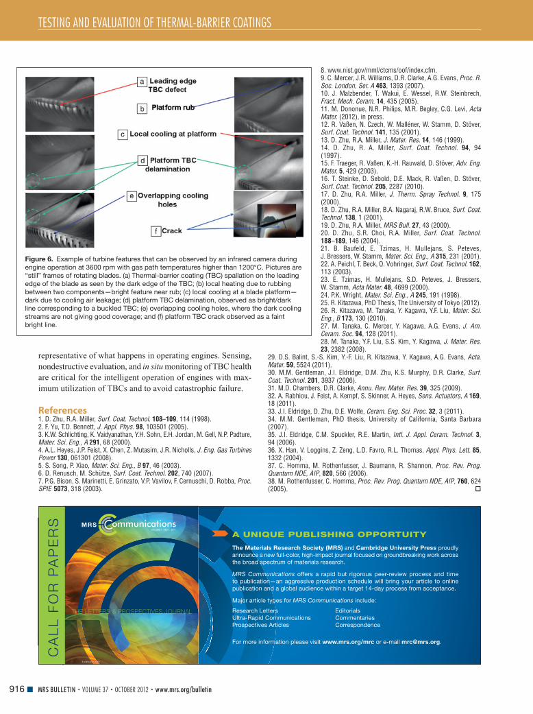
TESTING AND EVALUATION OF THERMAL-BARRIER COATINGS
916 MRS BULLETIN • VOLUME 37 • OCTOBER 2012 • www.mrs.org/bulletin
representative of what happens in operating engines. Sensing,
nondestructive evaluation, and in situ monitoring of TBC health
are critical for the intelligent operation of engines with max-
imum utilization of TBCs and to avoid catastrophic failure.
References 1. D. Zhu , R.A. Miller , Surf. Coat. Technol. 108 – 109 , 114 ( 1998 ). 2. F. Yu , T.D. Bennett , J. Appl. Phys. 98 , 103501 ( 2005 ). 3. K.W. Schlichting , K. Vaidyanathan , Y.H. Sohn , E.H. Jordan , M. Gell , N.P. Padture , Mater. Sci. Eng., A 291 , 68 ( 2000 ). 4. A.L. Heyes , J.P. Feist , X. Chen , Z. Mutasim , J.R. Nicholls , J. Eng. Gas Turbines Power 130 , 061301 ( 2008 ). 5. S. Song , P. Xiao , Mater. Sci. Eng., B 97 , 46 ( 2003 ). 6. D. Renusch , M. Schütze , Surf. Coat. Technol. 202 , 740 ( 2007 ). 7. P.G. Bison , S. Marinetti , E. Grinzato , V.P. Vavilov , F. Cernuschi , D. Robba , Proc. SPIE 5073 , 318 ( 2003 ).
Figure 6. Example of turbine features that can be observed by an infrared camera during
engine operation at 3600 rpm with gas path temperatures higher than 1200°C. Pictures are
“still” frames of rotating blades. (a) Thermal-barrier coating (TBC) spallation on the leading
edge of the blade as seen by the dark edge of the TBC; (b) local heating due to rubbing
between two components—bright feature near rub; (c) local cooling at a blade platform—
dark due to cooling air leakage; (d) platform TBC delamination, observed as bright/dark
line corresponding to a buckled TBC; (e) overlapping cooling holes, where the dark cooling
streams are not giving good coverage; and (f) platform TBC crack observed as a faint
bright line.
8. www . nist . gov / mml / ctcms / oof / index . cfm . 9. C. Mercer , J.R. Williams , D.R. Clarke , A.G. Evans , Proc. R. Soc. London, Ser. A 463 , 1393 ( 2007 ). 10. J. Malzbender , T. Wakui , E. Wessel , R.W. Steinbrech , Fract. Mech. Ceram. 14 , 435 ( 2005 ). 11. M. Dononue , N.R. Philips , M.R. Begley , C.G. Levi , Acta Mater. ( 2012 ), in press . 12. R. Vaßen , N. Czech , W. Malléner , W. Stamm , D. Stöver , Surf. Coat. Technol. 141 , 135 ( 2001 ). 13. D. Zhu , R.A. Miller , J. Mater. Res. 14 , 146 ( 1999 ). 14. D. Zhu , R. A. Miller , Surf. Coat. Technol. 94 , 94 ( 1997 ). 15. F. Traeger , R. Vaßen , K.-H. Rauwald , D. Stöver , Adv. Eng. Mater. 5 , 429 ( 2003 ). 16. T. Steinke , D. Sebold , D.E. Mack , R. Vaßen , D. Stöver , Surf. Coat. Technol. 205 , 2287 ( 2010 ). 17. D. Zhu , R.A. Miller , J. Therm. Spray Technol. 9 , 175 ( 2000 ). 18. D. Zhu , R.A. Miller , B.A. Nagaraj , R.W. Bruce , Surf. Coat. Technol. 138 , 1 ( 2001 ). 19. D. Zhu , R.A. Miller , MRS Bull. 27 , 43 ( 2000 ). 20. D. Zhu , S.R. Choi , R.A. Miller , Surf. Coat. Technol. 188 – 189 , 146 ( 2004 ). 21. B. Baufeld , E. Tzimas , H. Mullejans , S. Peteves , J. Bressers , W. Stamm , Mater. Sci. Eng., A 315 , 231 ( 2001 ). 22. A. Peichl , T. Beck , O. Vohringer , Surf. Coat. Technol. 162 , 113 ( 2003 ). 23. E. Tzimas , H. Mullejans , S.D. Peteves , J. Bressers , W. Stamm , Acta Mater. 48 , 4699 ( 2000 ). 24. P.K. Wright , Mater. Sci. Eng., A 245 , 191 ( 1998 ). 25. R. Kitazawa , PhD Thesis, The University of Tokyo (2012) . 26. R. Kitazawa , M. Tanaka , Y. Kagawa , Y.F. Liu , Mater. Sci. Eng., B 173 , 130 ( 2010 ). 27. M. Tanaka , C. Mercer , Y. Kagawa , A.G. Evans , J. Am. Ceram. Soc. 94 , 128 ( 2011 ). 28. M. Tanaka , Y.F. Liu , S.S. Kim , Y. Kagawa , J. Mater. Res. 23 , 2382 ( 2008 ).
29. D.S. Balint , S.-S. Kim , Y.-F. Liu , R. Kitazawa , Y. Kagawa , A.G. Evans , Acta. Mater. 59 , 5524 ( 2011 ). 30. M.M. Gentleman , J.I. Eldridge , D.M. Zhu , K.S. Murphy , D.R. Clarke , Surf. Coat. Technol. 201 , 3937 ( 2006 ). 31. M.D. Chambers , D.R. Clarke , Annu. Rev. Mater. Res. 39 , 325 ( 2009 ). 32. A. Rabhiou , J. Feist , A. Kempf , S. Skinner , A. Heyes , Sens. Actuators, A 169 , 18 ( 2011 ). 33. J.I. Eldridge , D. Zhu , D.E. Wolfe , Ceram. Eng. Sci. Proc. 32 , 3 ( 2011 ). 34. M.M. Gentleman , PhD thesis, University of California, Santa Barbara (2007) . 35. J.I. Eldridge , C.M. Spuckler , R.E. Martin , Intl. J. Appl. Ceram. Technol. 3 , 94 ( 2006 ). 36. X. Han , V. Loggins , Z. Zeng , L.D. Favro , R.L. Thomas , Appl. Phys. Lett. 85 , 1332 ( 2004 ). 37. C. Homma , M. Rothenfusser , J. Baumann , R. Shannon , Proc. Rev. Prog. Quantum NDE, AIP , 820 , 566 ( 2006 ). 38. M. Rothenfusser , C. Homma , Proc. Rev. Prog. Quantum NDE, AIP , 760 , 624 ( 2005 ).
THE LETTERS & PROSPECTIVES JOURNAL
VOLUME 1 NO 1, 2011
A publication of the
CA
LL
FO
R P
AP
ER
S
The Materials Research Society (MRS) and Cambridge University Press proudly
announce a new full-color, high-impact journal focused on groundbreaking work across
the broad spectrum of materials research.
MRS Communications offers a rapid but rigorous peer-review process and time
to publication—an aggressive production schedule will bring your article to online
publication and a global audience within a target 14-day process from acceptance.
Major article types for MRS Communications include:
A UNIQUE PUBLISHING OPPORTUITY
Research Letters
Ultra-Rapid Communications
Prospectives Articles
For more information please visit www.mrs.org/mrc or e-mail [email protected].
Editorials
Commentaries
Correspondence

917MRS BULLETIN • VOLUME 37 • OCTOBER 2012 • www.mrs.org/bulletin© 2012 Materials Research Society
Introduction The need for thermal-barrier coating (TBC) materials with
lower thermal conductivity than the currently used 7% yttria-
stabilized zirconia (7YSZ) composition that can also operate
in the strongly oxidative environment of combustion gases
has stimulated a worldwide effort to identify new oxide com-
positions (see the introductory article in this issue). It has also
stimulated a better understanding of the factors that determine
low thermal conductivity in crystalline solids at high temper-
atures. Although TBC materials must satisfy a wide range
of requirements, the primary performance metric is their
thermal conductivity at operating temperatures of 1250°C
and above. Depending on the processing technology and
conditions, the thermal conductivity of 7YSZ lies in the range
of 1.2–1.8 W m –1 K –1 ; we are therefore most interested in mate-
rials with thermal conductivities below ∼ 1 W m –1 K –1 . For the
foreseeable future, the operating temperatures are still not high
enough for appreciable radiative heat transfer unless the coating
material contains ions that absorb in the infrared. 1 As this article
will describe, an impressive number of new oxide materials
have been identifi ed in the last decade that have conductivities
lower than 7YSZ; the thermal conductivities of the emerging
ceramics for TBC are summarized in Figure 1 a–b. There are
good reasons to believe that the continued search, combining
crystal chemistry principles and simulation, will identify others.
Unless otherwise noted, all the conductivity values presented
are for fully dense materials without porosity, since porosity
can signifi cantly reduce the measured conductivity. Indeed,
porosity is deliberately introduced into TBCs to decrease the
thermal conductivity as well as increase strain compliance.
We provide an overview of recently identifi ed low thermal
conductivity oxides and discuss the mechanisms involved in
the minimization of the thermal conductivity.
Yttria-stabilized zirconia The most widely used TBC material is YSZ, zirconia containing
6–8 wt% Y 2 O 3 (equivalent to about 3.4–4.5 mol%), which is
produced in a metastable tetragonal phase (t’). 2 Alloying zirconia
with yttria is necessary to avoid the disruptive monoclinic to
tetragonal phase transformation that would otherwise cause
mechanical breakdown of the zirconia; however, it also reduces
the thermal conductivity by creating point defects that scatter
phonons. The introduction of Y 3+ as an aliovalent dopant on the
Zr 4+ site is compensated by vacant oxygen sites. Interestingly,
because of the similarity in atomic mass between the Y 3+ and
Zr 4+ ions, the oxygen vacancies are primarily responsible for
reducing thermal conductivity.
A physical picture of thermal transport in solids is given by
propagating lattice waves, known as phonons. Scattering of
these waves off of each other, as well as off of the defects in
Low thermal conductivity oxides Wei Pan , Simon R. Phillpot , Chunlei Wan , Aleksandr Chernatynskiy , and Zhixue Qu
Oxides hold great promise as new and improved materials for thermal-barrier coating
applications. The rich variety of structures and compositions of the materials in this class,
and the ease with which they can be doped, allow the exploration of various mechanisms for
lowering thermal conductivity. In this article, we review recent progress in identifying specifi c
oxides with low thermal conductivity from both theoretical and experimental perspectives.
We explore the mechanisms of lowering thermal conductivity, such as introducing structural/
chemical disorder, increasing material density, increasing the number of atoms in the primitive
cell, and exploiting the structural anisotropy. We conclude that further systematic exploration
of oxide crystal structures and chemistries are likely to result in even further improved
thermal-barrier coatings.
Wei Pan, State Key Lab of New Ceramics and Fine Processing , Tsinghua University , Beijing , China ; [email protected] Simon R. Phillpot, Department of Materials Science and Engineering , University of Florida , Gainesville , FL ; [email protected] .edu Chunlei Wan, Graduate School of Engineering , Nagoya University , Nagoya , Japan ; [email protected] Aleksandr Chernatynskiy, Department of Materials Science and Engineering , University of Florida , Gainesville , FL ; [email protected] Zhixue Qu, College of Materials Science and Engineering , Beijing University of Technology , Beijing , China ; [email protected] DOI: 10.1557/mrs.2012.234
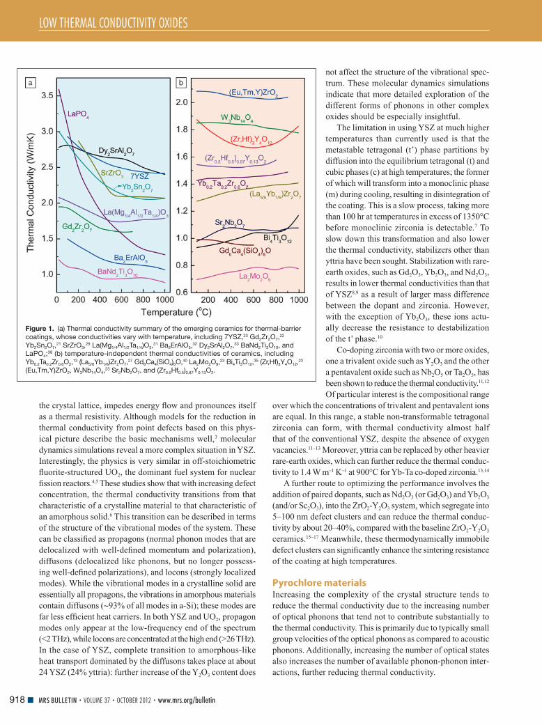
LOW THERMAL CONDUCTIVITY OXIDES
918 MRS BULLETIN • VOLUME 37 • OCTOBER 2012 • www.mrs.org/bulletin
the crystal lattice, impedes energy fl ow and pronounces itself
as a thermal resistivity. Although models for the reduction in
thermal conductivity from point defects based on this phys-
ical picture describe the basic mechanisms well, 3 molecular
dynamics simulations reveal a more complex situation in YSZ.
Interestingly, the physics is very similar in off-stoichiometric
fl uorite-structured UO 2 , the dominant fuel system for nuclear
fi ssion reactors. 4 , 5 These studies show that with increasing defect
concentration, the thermal conductivity transitions from that
characteristic of a crystalline material to that characteristic of
an amorphous solid. 6 This transition can be described in terms
of the structure of the vibrational modes of the system. These
can be classifi ed as propagons (normal phonon modes that are
delocalized with well-defi ned momentum and polarization),
diffusons (delocalized like phonons, but no longer possess-
ing well-defi ned polarizations), and locons (strongly localized
modes). While the vibrational modes in a crystalline solid are
essentially all propagons, the vibrations in amorphous materials
contain diffusons ( ∼ 93% of all modes in a-Si); these modes are
far less effi cient heat carriers. In both YSZ and UO 2 , propagon
modes only appear at the low-frequency end of the spectrum
(<2 THz), while locons are concentrated at the high end (>26 THz).
In the case of YSZ, complete transition to amorphous-like
heat transport dominated by the diffusons takes place at about
24 YSZ (24% yttria): further increase of the Y 2 O 3 content does
not affect the structure of the vibrational spec-
trum. These molecular dynamics simulations
indicate that more detailed exploration of the
different forms of phonons in other complex
oxides should be especially insightful.
The limitation in using YSZ at much higher
temperatures than currently used is that the
metastable tetragonal (t’) phase partitions by
diffusion into the equilibrium tetragonal (t) and
cubic phases (c) at high temperatures; the former
of which will transform into a monoclinic phase
(m) during cooling, resulting in disintegration of
the coating. This is a slow process, taking more
than 100 hr at temperatures in excess of 1350°C
before monoclinic zirconia is detectable. 7 To
slow down this transformation and also lower
the thermal conductivity, stabilizers other than
yttria have been sought. Stabilization with rare-
earth oxides, such as Gd 2 O 3 , Yb 2 O 3 , and Nd 2 O 3 ,
results in lower thermal conductivities than that
of YSZ 8 , 9 as a result of larger mass difference
between the dopant and zirconia. However,
with the exception of Yb 2 O 3 , these ions actu-
ally decrease the resistance to destabilization
of the t’ phase. 10
Co-doping zirconia with two or more oxides,
one a trivalent oxide such as Y 2 O 3 and the other
a pentavalent oxide such as Nb 2 O 5 or Ta 2 O 5 , has
been shown to reduce the thermal conductivity. 11 , 12
Of particular interest is the compositional range
over which the concentrations of trivalent and pentavalent ions
are equal. In this range, a stable non-transformable tetragonal
zirconia can form, with thermal conductivity almost half
that of the conventional YSZ, despite the absence of oxygen
vacancies. 11 – 13 Moreover, yttria can be replaced by other heavier
rare-earth oxides, which can further reduce the thermal conduc-
tivity to 1.4 W m –1 K –1 at 900°C for Yb-Ta co-doped zirconia. 13 , 14
A further route to optimizing the performance involves the
addition of paired dopants, such as Nd 2 O 3 (or Gd 2 O 3 ) and Yb 2 O 3
(and/or Sc 2 O 3 ), into the ZrO 2 -Y 2 O 3 system, which segregate into
5–100 nm defect clusters and can reduce the thermal conduc-
tivity by about 20–40%, compared with the baseline ZrO 2 -Y 2 O 3
ceramics. 15 – 17 Meanwhile, these thermodynamically immobile
defect clusters can signifi cantly enhance the sintering resistance
of the coating at high temperatures.
Pyrochlore materials Increasing the complexity of the crystal structure tends to
reduce the thermal conductivity due to the increasing number
of optical phonons that tend not to contribute substantially to
the thermal conductivity. This is primarily due to typically small
group velocities of the optical phonons as compared to acoustic
phonons. Additionally, increasing the number of optical states
also increases the number of available phonon-phonon inter-
actions, further reducing thermal conductivity.
Figure 1. (a) Thermal conductivity summary of the emerging ceramics for thermal-barrier
coatings, whose conductivities vary with temperature, including 7YSZ, 23 Gd 2 Zr 2 O 7 , 22
Yb 2 Sn 2 O 7 , 21 SrZrO 3 ,
29 La(Mg 1/4 Al 1/2 Ta 1/4 )O 3 , 31 Ba 2 ErAlO 5 ,
32 Dy 2 SrAl 2 O 7 , 33 BaNd 2 Ti 3 O 10 , and
LaPO 4 ; 38 (b) temperature-independent thermal conductivities of ceramics, including
Yb 0.2 Ta 0.2 Zr 0.6 O 2 , 13 (La 5/6 Yb 1/6 )Zr 2 O 7 ,
27 Gd 6 Ca 4 (SiO 4 ) 6 O, 40 La 2 Mo 2 O 9 , 23 Bi 4 Ti 3 O 12 ,
35 (Zr,Hf) 3 Y 4 O 12 , 23
(Eu,Tm,Y)ZrO 2 , W 3 Nb 14 O 4 , 23 Sr 2 Nb 2 O 7 , and (Zr 0.5 Hf 0.5 ) 0.87 Y 0.13 O 2 .

LOW THERMAL CONDUCTIVITY OXIDES
919MRS BULLETIN • VOLUME 37 • OCTOBER 2012 • www.mrs.org/bulletin
The A 2 B 2 O 7 -pyrochlore structure is one of a number of
more complex crystal structures based on the fl uorite structure
of zirconia. It has a unit cell consisting of eight fl uorite-like
subcells, each of which contains one vacant oxygen site defect
(the subcell of the pyrochlore structure is shown in Figure 2a ).
Both the presence of vacant sites and the larger unit cell should
lower the thermal conductivity. Indeed, pyrochlore compounds
of rare earth zirconates (where A= rare-earth element and
B = Zr) exhibit extremely low thermal conductivity, ranging
from ∼ 1.1–1.7 W m –1 K –1 at temperatures between 700°C and
1200°C for A = La, Eu, Sm, Nd, and Gd. 18 The stability of the
pyrochlore structure is sensitive to the ratio of the A and B
cation radii. 19 Thermal conductivity simulations have been
performed on the large family of pyrochlores with A = La, Pr,
Nd, Sm, Eu, Gd, Y, Er, or Lu and B = Ti, Mo, Sn, Zr, or Pb. 20
Figure 3 presents the resultant map of the thermal conductivity
as a function of the A and B ionic radii. Of particular note is
that increasing the B-cation radii consistently reduces thermal
conductivity, whereas the A cation size has less of an effect. As
yet, there is insuffi cient experimental data to confi rm the details
of this property map. 21 Large rare-earth ions in Ln 2 Zr 2 O 7
(Ln = La, Nd, Sm, Gd) can lead to a stable pyrochlore structure
up to at least 1500°C. 22 Gd 2 Zr 2 O 7 can also take
on a defected fl uorite structure ( Figure 2b ) if
suitably heat-treated, but the thermal conductivity
was found to be the same as its pyrochlore coun-
terpart. 22 It is interesting to note that a different
defective fl uorite structure, the delta-phase, is
formed with smaller rare-earth ions, such as Dy,
Er, Yb, and Y, and that these too have thermal
conductivity similar to those of pyrochlores. 23 , 24
The expectation that doping and alloying
will reduce thermal conductivity is borne out
experimentally. Some success has been achieved,
at least up to ∼ 800°C, as exemplified by
La 2 Zr 2 O 7 , which when doped with 30 at.% Gd
displays a decrease in thermal conductivity from
∼ 1.55 W m –1 K –1 to ∼ 0.9 W m –1 K –1 . 25 In addition
to lowering the thermal conductivity due to alloy
scattering, doping can change the pyrochlore
structure itself in ways that affect the thermal con-
ductivity. 26 For example, in the (Sm 1– x Yb x ) 2 Zr 2 O 7
series, there is a transition from pyrochlore to a
more disordered fl uorite state when the x value
lies between 1/6 and 1/3, at which there is
also a dip in the thermal conductivity. 26 By con-
trast, in (La 1– x Yb x ) 2 Zr 2 O 7 , the Yb 3+ was found to
“rattle” (undergo very large localized thermal
vibration) at the 16 c -site, which could lead
to a glass-like thermal conductivity. 27 Among
the mentioned pyrochlores, some oxides such
as Sm 2 Zr 2 O 7 , Gd 2 Zr 2 O 7 , and their composites
may become the potential materials for TBCs,
owing to the better comprehensive mechanical
and thermal performances.
Perovskite-structured oxides The ABO 3 -type perovskites are another class of material
that show both a large number of options for the A and B
Figure 2. (a) A 1/8 unit cell of the A 2 B 2 O 7 -type pyrochlore structure that can be adopted
by low thermal conductivity rare-earth zirconates (A = rare earth element, B = Zr),
indicating lattice sites and the unoccupied oxygen position. (b) The defect fl uorite
structure that can be induced in heavier rare-earth zirconates or by heat treatment of
pyrochlore-type Gd 2 Zr 2 O 7 and shows similar thermal conductivities to the pyrochlores.
In this structure, the cations are completely disordered, and the occupancy for each anion
site is 0.875. 33 (c) An example of a perovskite-structured oxide: The layered Ruddlesden–
Popper phase of Sr-Ti-O. 34 The oxygen octahedra of the two perovskite unit cells are
outlined in blue, and the single rock salt layer is shown at the top.
Figure 3. Contour map of thermal conductivity ( κ ) determined
at T = 1473 K by simulation, as a function of ionic radii of the
A and B ions for pyrochlore A 2 B 2 O 7 . 20

LOW THERMAL CONDUCTIVITY OXIDES
920 MRS BULLETIN • VOLUME 37 • OCTOBER 2012 • www.mrs.org/bulletin
cations, and display a large number of structural variants. 28
They therefore seem to be good candidates for engineering
the thermal conductivity. Pure ABO 3 perovskites containing
high atomic mass ions exhibit low thermal conductivities, for
example, 2.1 W m –1 K –1 for SrZrO 3 29 and 3.4 W m –1 K –1 for
BaZrO 3 18 at 1000°C on account of the structural rigidity of
corner-shared octahedra. 29 However, following the strategy
that was so successful for fl uorite, Yb 2 O 3 has been doped onto
the B site of SrZrO 3 , leading to a 20% reduction in the thermal
conductivity over the temperature range of 200–1200°C. 30
Moreover, increasing the doping level can lead to new complex
perovskite structures. For example, Ba(Mg 1/3 Ta 2/3 )O 3 has a
melting temperature of ∼ 3000°C and is considered among the
most refractory of all oxides; 15 its thermal conductivity reaches
2.5 W m –1 K –1 at 1100°C. Likewise, the La(Al 1/4 Mg 1/2 Ta 1/4 )O 3
complex perovskite system shows a low value of thermal conduc-
tivity ( ∼ 2 W m –1 K –1 ) and high coeffi cient of thermal expansion
( ∼ 11.9 × 10 –6 K –1 ), which is a promising combination for TBC
applications. However, TBCs made of these complex perovskites
show short thermal cycling life, possibly due to their low tough-
ness and consequent weak thermal shock resistance. 31
Bearing a similar relationship to the perovskite struc-
ture as the pyrochlore structure does to fl uorite, Ba 2 LnAlO 5
(Ln = lanthanide element), in which one-sixth of the oxygen sites
in the perovskite structure are vacant, has a thermal conductivity
of only 1.1 W m –1 K –1 at 1000°C. 32 Again following the strategy of
increasing the size of the unit cell and increasing the number
of atoms per unit cell, thereby increasing the number of optical
phonons and reducing the thermal conductivity, the perovskite
structure can also be a building block for complex superlattice
structures. The thermal conductivities of Ruddlesden–Popper
(RP) structures of Ln 2 SrAl 2 O 7 33 and Sr n +1 Ti n O 3 n +1
34 ( Figure 2 c),
the Aurivillius phases 35 of Bi 4 Ti 3 O 12 , and the Dion–Jacobson
phases of BaLa 2 Ti 3 O 10 36 have been studied, all producing
thermal conductivities of 1–2 W m –1 K –1 , which are substantially
lower than the typical value of 2.5 W m –1 K –1
for 7YSZ. As shown in Figure 2c , the RP
structure consists of n (n = 1, 2,...) layers of
perovskite structured material separated by a
rock salt structured layer; the Aurivillius and
Dion–Jacobson phases show analogous layered
perovskite structures.
Lanthanide orthophosphates and silicates The lanthanide orthophosphates (LnPO 4 )
are another set of compounds with low ther-
mal conductivities. 37 The orthophosphates can
take on either a monazite or xenotime crystal
structure, depending on the ionic size of the
lanthanide ions. Monazite LnPO 4 (Ln = La-Gd)
is expected to show a distinctly lower thermal
conductivity than the xenotime structure com-
pounds due to its lower crystal symmetry and
weaker bonds. 23 , 38 The anisotropy of thermal
conductivity of the most studied monazite compound LaPO 4 is
also noticeable, due to the non-cubic crystal structure. 39 How-
ever, the characteristics of the line compound (small deviations
from the stoichiometry can signifi cantly change the solidus tem-
perature, thereby making it hard to apply the plasma spraying
process to make coatings) and poor adherence to the bond-coat
layer (between the TBC and the superalloy) limits the applica-
tions of LaPO 4 as a TBC. 37
Based on their large unit cell and complex structures, the
rare-earth silicates ( Figure 4 ) can be expected to yield low
thermal conductivity values. Among these, apatite structured
Gd 8 Ca 2 (SiO 4 ) 6 O 2 has attracted particular attention; 40 it exhibits
an extremely low and temperature-independent thermal
conductivity of about 1.4 W m –1 K –1 for almost fully dense
samples. Another interesting feature of this compound is that
the composition can be systematically altered by adjusting
the relative proportions of alkaline earth cations and rare-
earth ions to introduce different populations of oxygen
vacancies, cation vacancies, and oxygen interstitials, resulting
in even lower thermal conductivities for defect-containing
compositions ( Figure 5 ). 40
Thermal expansion coeffi cient While thermal conductivity is the key performance metric for
potential TBC materials, it is also essential that they be ther-
momechanically compatible with both the superalloy that they
coat and the intermediate bonding layers (see the introduc-
tory article in this issue). The thermal expansion coeffi cient
of YSZ is 10.7 × 10 –6 K –1 from room temperature to 1273 K, 41
while those of the typical superalloy substrate and bond coat
(NiCrAlY) are 16 × 10 –6 K –1 and 17.5 × 10 –6 K –1 , respectively,
for the same temperature range. 41 This mismatch can lead to
high thermal stresses that have the potential to promote coating
failure. Although YSZ coatings can last tens of thousands of
hours and multiple cycling without failing, it is still believed
Figure 4. View of the crystal structure of the stoichiometric rare-earth apatites
A 10 (SiO 4 ) 6 O 2+ δ , along the [001] axis, and the location of the two types of cation sites, A1 and
A2, as well as the oxygen sites, O4. 40 The complexity and large unit cell of this structure is
believed to give rise to low thermal conductivity in materials such as Gd 8 Ca 2 (SiO 4 ) 6 O 2.
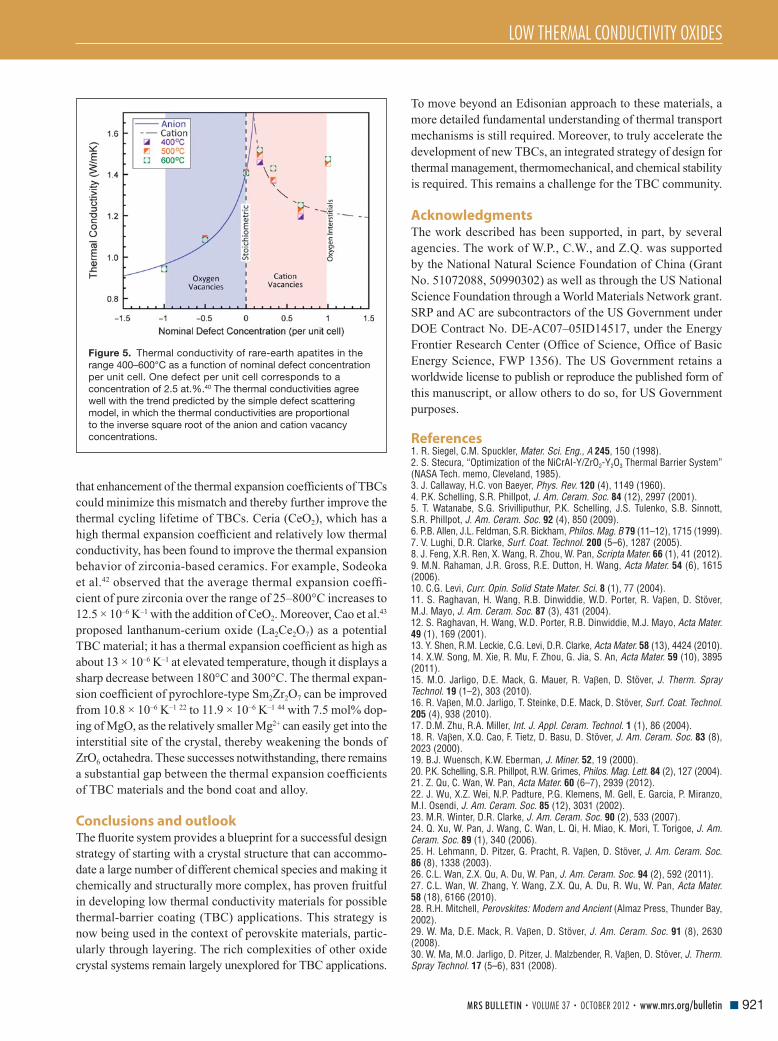
LOW THERMAL CONDUCTIVITY OXIDES
921MRS BULLETIN • VOLUME 37 • OCTOBER 2012 • www.mrs.org/bulletin
that enhancement of the thermal expansion coeffi cients of TBCs
could minimize this mismatch and thereby further improve the
thermal cycling lifetime of TBCs. Ceria (CeO 2 ), which has a
high thermal expansion coeffi cient and relatively low thermal
conductivity, has been found to improve the thermal expansion
behavior of zirconia-based ceramics. For example, Sodeoka
et al. 42 observed that the average thermal expansion coeffi -
cient of pure zirconia over the range of 25–800°C increases to
12.5 × 10 –6 K –1 with the addition of CeO 2 . Moreover, Cao et al. 43
proposed lanthanum-cerium oxide (La 2 Ce 2 O 7 ) as a potential
TBC material; it has a thermal expansion coeffi cient as high as
about 13 × 10 –6 K –1 at elevated temperature, though it displays a
sharp decrease between 180°C and 300°C. The thermal expan-
sion coeffi cient of pyrochlore-type Sm 2 Zr 2 O 7 can be improved
from 10.8 × 10 –6 K –1 22 to 11.9 × 10 –6 K –1 44 with 7.5 mol% dop-
ing of MgO, as the relatively smaller Mg 2+ can easily get into the
interstitial site of the crystal, thereby weakening the bonds of
ZrO 6 octahedra. These successes notwithstanding, there remains
a substantial gap between the thermal expansion coeffi cients
of TBC materials and the bond coat and alloy.
Conclusions and outlook The fl uorite system provides a blueprint for a successful design
strategy of starting with a crystal structure that can accommo-
date a large number of different chemical species and making it
chemically and structurally more complex, has proven fruitful
in developing low thermal conductivity materials for possible
thermal-barrier coating (TBC) applications. This strategy is
now being used in the context of perovskite materials, partic-
ularly through layering. The rich complexities of other oxide
crystal systems remain largely unexplored for TBC applications.
Figure 5. Thermal conductivity of rare-earth apatites in the
range 400–600°C as a function of nominal defect concentration
per unit cell. One defect per unit cell corresponds to a
concentration of 2.5 at.%. 40 The thermal conductivities agree
well with the trend predicted by the simple defect scattering
model, in which the thermal conductivities are proportional
to the inverse square root of the anion and cation vacancy
concentrations.
To move beyond an Edisonian approach to these materials, a
more detailed fundamental understanding of thermal transport
mechanisms is still required. Moreover, to truly accelerate the
development of new TBCs, an integrated strategy of design for
thermal management, thermomechanical, and chemical stability
is required. This remains a challenge for the TBC community.
Acknowledgments The work described has been supported, in part, by several
agencies. The work of W.P., C.W., and Z.Q. was supported
by the National Natural Science Foundation of China (Grant
No. 51072088, 50990302) as well as through the US National
Science Foundation through a World Materials Network grant.
SRP and AC are subcontractors of the US Government under
DOE Contract No. DE-AC07–05ID14517, under the Energy
Frontier Research Center (Offi ce of Science, Offi ce of Basic
Energy Science, FWP 1356). The US Government retains a
worldwide license to publish or reproduce the published form of
this manuscript, or allow others to do so, for US Government
purposes.
References 1. R. Siegel , C.M. Spuckler , Mater. Sci. Eng., A 245 , 150 ( 1998 ). 2. S. Stecura , “Optimization of the NiCrAI-Y/ZrO 2 -Y 2 O 3 Thermal Barrier System” (NASA Tech. memo, Cleveland , 1985 ). 3. J. Callaway , H.C. von Baeyer , Phys. Rev. 120 ( 4 ), 1149 ( 1960 ). 4. P.K. Schelling , S.R. Phillpot , J. Am. Ceram. Soc. 84 ( 12 ), 2997 ( 2001 ). 5. T. Watanabe , S.G. Srivilliputhur , P.K. Schelling , J.S. Tulenko , S.B. Sinnott , S.R. Phillpot , J. Am. Ceram. Soc. 92 ( 4 ), 850 ( 2009 ). 6. P.B. Allen , J.L. Feldman , S.R. Bickham , Philos. Mag. B 79 ( 11–12 ), 1715 ( 1999 ). 7. V. Lughi , D.R. Clarke , Surf. Coat. Technol. 200 ( 5–6 ), 1287 ( 2005 ). 8. J. Feng , X.R. Ren , X. Wang , R. Zhou , W. Pan , Scripta Mater. 66 ( 1 ), 41 ( 2012 ). 9. M.N. Rahaman , J.R. Gross , R.E. Dutton , H. Wang , Acta Mater. 54 ( 6 ), 1615 ( 2006 ). 10. C.G. Levi , Curr. Opin. Solid State Mater. Sci. 8 ( 1 ), 77 ( 2004 ). 11. S. Raghavan , H. Wang , R.B. Dinwiddie , W.D. Porter , R. Va β en , D. Stöver , M.J. Mayo , J. Am. Ceram. Soc. 87 ( 3 ), 431 ( 2004 ). 12. S. Raghavan , H. Wang , W.D. Porter , R.B. Dinwiddie , M.J. Mayo , Acta Mater. 49 ( 1 ), 169 ( 2001 ). 13. Y. Shen , R.M. Leckie , C.G. Levi , D.R. Clarke , Acta Mater. 58 ( 13 ), 4424 ( 2010 ). 14. X.W. Song , M. Xie , R. Mu , F. Zhou , G. Jia , S. An , Acta Mater. 59 ( 10 ), 3895 ( 2011 ). 15. M.O. Jarligo , D.E. Mack , G. Mauer , R. Va β en , D. Stöver , J. Therm. Spray Technol. 19 ( 1–2 ), 303 ( 2010 ). 16. R. Va β en , M.O. Jarligo , T. Steinke , D.E. Mack , D. Stöver , Surf. Coat. Technol. 205 ( 4 ), 938 ( 2010 ). 17. D.M. Zhu , R.A. Miller , Int. J. Appl. Ceram. Technol. 1 ( 1 ), 86 ( 2004 ). 18. R. Va β en , X.Q. Cao , F. Tietz , D. Basu , D. Stöver , J. Am. Ceram. Soc. 83 ( 8 ), 2023 ( 2000 ). 19. B.J. Wuensch , K.W. Eberman , J. Miner. 52 , 19 ( 2000 ). 20. P.K. Schelling , S.R. Phillpot , R.W. Grimes , Philos. Mag. Lett. 84 ( 2 ), 127 ( 2004 ). 21. Z. Qu , C. Wan , W. Pan , Acta Mater. 60 ( 6–7 ), 2939 ( 2012 ). 22. J. Wu , X.Z. Wei , N.P. Padture , P.G. Klemens , M. Gell , E. Garcia , P. Miranzo , M.I. Osendi , J. Am. Ceram. Soc. 85 ( 12 ), 3031 ( 2002 ). 23. M.R. Winter , D.R. Clarke , J. Am. Ceram. Soc. 90 ( 2 ), 533 ( 2007 ). 24. Q. Xu , W. Pan , J. Wang , C. Wan , L. Qi , H. Miao , K. Mori , T. Torigoe , J. Am. Ceram. Soc. 89 ( 1 ), 340 ( 2006 ). 25. H. Lehmann , D. Pitzer , G. Pracht , R. Va β en , D. Stöver , J. Am. Ceram. Soc. 86 ( 8 ), 1338 ( 2003 ). 26. C.L. Wan , Z.X. Qu , A. Du , W. Pan , J. Am. Ceram. Soc. 94 ( 2 ), 592 ( 2011 ). 27. C.L. Wan , W. Zhang , Y. Wang , Z.X. Qu , A. Du , R. Wu , W. Pan , Acta Mater. 58 ( 18 ), 6166 ( 2010 ). 28. R.H. Mitchell , Perovskites: Modern and Ancient ( Almaz Press , Thunder Bay , 2002 ). 29. W. Ma , D.E. Mack , R. Va β en , D. Stöver , J. Am. Ceram. Soc. 91 ( 8 ), 2630 ( 2008 ). 30. W. Ma , M.O. Jarligo , D. Pitzer , J. Malzbender , R. Va β en , D. Stöver , J. Therm. Spray Technol. 17 ( 5–6 ), 831 ( 2008 ).
LOW THERMAL CONDUCTIVITY OXIDES
922 MRS BULLETIN • VOLUME 37 • OCTOBER 2012 • www.mrs.org/bulletin
31. M.O. Jarligo , D.E. Mack , R. Va β en , D. Stöver , J. Therm. Spray Technol. 18 ( 2 ), 187 ( 2009 ). 32. C. Wan , Z. Qu , Y. He , D. Luan , W. Pan , Phys. Rev. Lett. 101 ( 8 ), 085901 ( 2008 ). 33. C.L. Wan , T.D. Sparks , W. Pan , D.R. Clarke , R. David , J. Am. Ceram. Soc. 93 ( 5 ), 1457 ( 2010 ). 34. A. Chernatynskiy , R.W. Grimes , M.A. Zurbuchen , D.R. Clarke , S.R. Phillpot , Appl. Phys. Lett. 95 ( 16 ) ( 2009 ). 35. Y. Shen , D.R. Clarke , P.A. Fuierer , Appl. Phys. Lett. 93 ( 10 ) ( 2008 ). 36. H. Guo , H. Zhang , G. Ma , S. Gong , Surf. Coat. Technol. 204 ( 5 ), 691 ( 2009 ). 37. X.Q. Cao , R. Va β en , D. Stöver , J. Eur. Ceram. Soc. 24 ( 1 ), 1 ( 2004 ).
38. A.B. Du , C.L. Wan , Z. Qu , W. Pan , J. Am. Ceram. Soc. 92 ( 11 ), 2687 ( 2009 ). 39. A.B. Du , C.L. Wan , Z. Qu , R. Wu , W. Pan , J. Am. Ceram. Soc. 93 ( 9 ), 2822 ( 2010 ). 40. Z.X. Qu , T.D. Sparks , W. Pan , D.R. Clarke , Acta Mater. 59 ( 10 ), 3841 ( 2011 ). 41. R. Va β en , G. Kerkhof , D. Stöver , Mater. Sci. Eng., A 303 ( 1–2 ), 100 ( 2001 ). 42. S. Sodeoka , M. Suzuki , K. Ueno . H. Sakuramoto , T. Shibata , M. Ando , J. Therm. Spray Technol. 6 ( 3 ), 361 ( 1997 ). 43. X.Q. Cao , R. Va β en , W. Fischer , F. Tietz , W. Jungen , D. Stöve , Adv. Mater. 15 ( 17 ), 1438 ( 2003 ). 44. Z.X. Qu , C.L. Wan , W. Pan , Chem. Mater. 19 ( 20 ), 4913 ( 2007 ).
Meet Your Next Employer …
Show off your talents to the world’s most prestigious
universities, laboratories and high-tech firms. FREE of
charge to all MRS Members, the Career Center provides
targeted employment opportunities to candidates seeking
positions in the scientific community.
Review open positions tailored to the materials research industry
Interview with prospective employers
Visit on-site recruitment booths and network with technical staff
For additional information, visit www.mrs.org/fall2012
Hynes Convention Center Level 2, Hall C
Registration: Monday, November 26
1:00 pm – 4:00 pm
Hours: Tuesday, November 27
11:00 am – 5:00 pm
Wednesday, November 28
11:00 am – 5:00 pm
Thursday, November 29
10:00 am – 1:30 pm
Do the research to advance your career…visit the MRS Career Center in Boston!
Established 1964
Catalog of Chemicals for R&D
Nano Products
CVD/ALD Precursors
Chemicals for R&D CVD/ALD Precursors Nanomaterials Bubblers & Cylinders High Purity Inorganics
93-1360 97-3425
PURE NP’s via laser ablation
Chemicals, Inc. Visit www.strem.com/mrs An Employee-Owned Company for more information. Serving Customers Globally
Corporate Headquarters Europe Newburyport, MA 01950 USA · email: [email protected] 67800 Bischheim, France · email: [email protected]
website: www.strem.com
Quantum Dots
InAl
CH3
H3C CH3
Bubblers/Cylinders

923MRS BULLETIN • VOLUME 37 • OCTOBER 2012 • www.mrs.org/bulletin© 2012 Materials Research Society
Introduction Thermal-barrier systems are an excellent example of multilay-
ered, multifunctional material assemblies that have enabled
substantial improvements in the performance and effi ciency of
gas turbine engines. The combination of a metallic substrate, an
intermetallic (or mixed metallic and intermetallic) interlayer,
and a low conductivity ceramic topcoat permits the system to
operate near, or even above, the melting point of the substrate
in a highly oxidizing combustion environment. 1–7
Intermetallic coatings have long been a central requirement
for high temperature operation of propulsion and power gen-
eration systems. In early applications in aero- and land-based
turbines (before ceramic thermal barriers were developed),
environmental coatings typically served a single function.
Aluminide-type coatings based on NiAl and NiCoCrAl-family
coatings became the standard systems for oxidation protection,
while diffusion chromides and overlay CoNiCrAl materials
were used to protect against hot corrosion. 1,6 As turbine oper-
ating temperatures have increased, fuels have become cleaner,
substrate alloys have evolved to refractory-rich nickel-based
single crystals, and environmental coatings have become (by
necessity) multifunctional. In current turbine components (see
Figure 1 in the introductory article for a depiction of a gas
turbine), a single coating deposited on a turbine blade may
be expected to: 1–9
• Resist Type II hot corrosion in cooler sections (e.g., in blade
shanks).
• Resist Type I hot corrosion in intermediate-temperature
regions (e.g., below the blade platform and in cooler sec-
tions of airfoils).
• Resist high-temperature oxidation in the hottest sections
(e.g., blade tips, platforms, and airfoils).
• Maintain adhesion to the thermal-barrier coating (TBC).
• Provide environmental protection in the event of TBC
spallation.
• Minimize interdiffusion and limit transformations at the
interface with the nickel-based substrate.
The challenges of developing intermetallic bond coatings
that will reliably perform in present and future engineering
systems are addressed in this article. A perspective on pres-
ently available bond coating systems and their functionality
is given fi rst. The suite of processing approaches for inter-
layer synthesis and challenges in controlling structure and
composition are then addressed. Aspects of the bond coating
that limit system performance are reviewed. New experi-
mental and characterization tools and computational design
approaches are highlighted, along with future prospects for
discovery of new materials combinations and for prediction
of their performance in complex thermo-chemical-mechanical
environments.
Multifunctional coating interlayers for thermal-barrier systems T.M. Pollock , D.M. Lipkin , and K.J. Hemker
The complex thermochemical and thermomechanical environments in high temperature
propulsion and energy generation systems often demand the use of suites of materials
with disparate properties. Unique combinations of materials that simultaneously function
to optimize mechanical, thermal, and environmental properties can enable breakthroughs in
design and system capability. This article focuses on interlayers that function as environmental
barriers and promote adhesion of the ceramic thermal barriers to metallic substrates. The
structure, composition, processing, and performance of major classes of bond coatings are
briefl y reviewed. Challenges for the development of new coating systems and for prediction
of their performance in service are addressed.
T.M. Pollock, Materials Department , University of California , Santa Barbara ; [email protected] D.M. Lipkin, GE Global Research , Fairfi eld , CT ; [email protected] K.J. Hemker, Department of Mechanical Engineering , Whiting School of Engineering , The Johns Hopkins University ; [email protected] DOI: 10.1557/mrs.2012.238

MULTIFUNCTIONAL COATING INTERLAYERS FOR THERMAL-BARRIER SYSTEMS
924 MRS BULLETIN • VOLUME 37 • OCTOBER 2012 • www.mrs.org/bulletin
Structure, functionality, and classes of bond coatings The intermetallic bond coat exists as an intermediate layer
between the metallic substrate (typically a nickel-based super-
alloy) and the ceramic top coating (typically yttria-stabilized
zirconia). The thickness of the bond-coat layer is typically
between 30–100 μ m, varying in thickness as a function of
processing approach and service time. The bond coating is
chemically complex due to the need to optimize a broad set of
thermomechanical and thermochemical properties.
Given that bond coatings are deposited on Ni-based sub-
strates and upon high temperature exposure from surface
fi lms of either chromia or alumina, the Ni-Al-Cr ternary
diagram at 1100°C, Figure 1 , is relevant. In the ternary com-
positional space, phases that exist include the B2 β phase
with approximately equal levels of Ni and Al, the fcc γ -Ni
and γ -Al phases, the L1 2 γ ′ –Ni 3 Al phase, and the A2 α -Cr
phase. These phases are often present in as-deposited coat-
ings. Bond coatings can be broadly classifi ed by these major
phase constituents. 1 , 2 , 7 Coatings comprised primarily of the
B2 β phase are typically referred to as “nickel aluminide”
coatings, and if they additionally contain platinum are clas-
sifi ed as “platinum aluminides.” A combination of the β and
γ ′ phases forms the basis of “MCrAlY” coatings, where the
“M” often refers to Ni, Co, or a combination of both. Several
emerging coating systems contain a γ ′ phase with some level
of γ –Ni present.
The high temperature processing paths for application of
the coatings, discussed in more detail in the next section,
inevitably include interdiffusion with the substrate, resulting
in an interdiffusion zone that may contain several additional
refractory-rich phases. Moreover, the bond-coat structure
evolves by interdiffusion during high temperature exposure,
potentially resulting in further phase transformations and/or
migration of elements that are detrimental to system perfor-
mance ( Figure 2 ). Calculated phase diagrams for higher order
multicomponent systems can be useful for avoiding the forma-
tion of brittle intermetallic phases in this zone and for designing
thermal treatments that follow coating application. Given the
operating environments for these coatings, control of both the
thermodynamic and kinetic properties is essential.
The bond coating must serve as an environmental barrier
for the substrate due to the fact that the outer, low conductivity
ceramic is permeable to oxygen. Consequently, the ability to
form a dense, protective oxide in the operating environment is
one of the primary requirements of the bond coating. Most of
the intermetallics presently employed as bond coatings contain
a suffi ciently high level of aluminum to promote the formation
of a dense α -Al 2 O 3 layer at the surface of the bond coat adjacent
to the TBC, which has a relatively slow growth rate and is
resistant to degradation by any corrosive species that reach the
surface through the thermal barrier, or subsequent to spallation
of the ceramic thermal barrier. 2 – 9 The thin oxide layer is typi-
cally referred to as the thermally grown oxide (TGO). Given the
high temperature operating requirements, it is essential that the
TGO be thermodynamically compatible with the ceramic ther-
mal barrier. To achieve the protective requirements, the bond
coating must serve as a chemical reservoir for TGO formation,
as well as a diffusion barrier or diffusion sink for any deleterious
refractory elements from the superalloy substrate that may degrade
the bond-coat properties or the bond coat—TGO interface
adhesion. 10 – 14 While the TGO provides the coating system with
an oxidation benefi t, this thin interlayer may also endure large
thermal and growth stresses that challenge the durability of the
layered TBC system when exposed to severe
thermal transients characteristic of turbine
airfoils, as discussed in more detail later.
To be effective over the life span of the tur-
bine component for which the bond coating is
intended to protect the substrate, it must also
be thermochemically and thermomechanically
compatible with the substrate so as to prevent—or
at least limit—debits to the mechanical prop-
erties of the load-bearing components. At pres-
ent, coatings are still not relied upon to provide
load-bearing capability, though this may be on
the horizon for the next generation of coatings.
In addition to their functional requirements,
the coatings must be applied using processes
that are cost effective, capable of providing the
required thickness and chemical homogeneity,
and compatible with other processes or thermal
operations required for component fabrication.
These requirements drive the development of
new coating compositions, architectures, and
the processes to fabricate them, discussed in
the following section.
Figure 1. Ternary Ni-Al-Cr phase diagram predicted by the Calphad method, and
approximate compositions of three different bond coating classes shown in scanning
electron micrographs on the right. Shifts in the amounts of Al, Cr, and Ni in these coatings
permit changes in the predominant phase.

MULTIFUNCTIONAL COATING INTERLAYERS FOR THERMAL-BARRIER SYSTEMS
925MRS BULLETIN • VOLUME 37 • OCTOBER 2012 • www.mrs.org/bulletin
Coating application: A multiplicity of processing paths As coating compositions have evolved to keep up with the
functional demands of engineering components, so too have
the processes for depositing them. While coating compositions
can be optimized solely on their chemical and microstructural
characteristics, it is essential to have a coating process capable
of uniformly covering the complex geometries of the turbine
components and compatible with all subsequent manufacturing
processes, such as TBC deposition, heat treatments used to
establish braze joints, and any heat treatments used to establish
the desired substrate properties. The challenge of delivering
ever-increasing coating functionality while maintaining robust
and cost-effective manufacturing processes has led to a multi-
plicity of coating processes, which may be broadly classifi ed
into two categories: diffusion coatings and overlays.
Diff usion coatings Diffusion coatings, particularly aluminide coatings, are the
product of interdiffusion between the superalloy component
and an aluminum source (donor). The simplest of these pro-
cesses, and the earliest to be industrially implemented, is pack
cementation, 15 schematically illustrated in Figure 3 a. Com-
ponents to be aluminized are embedded into a mixture of the
aluminum source, an inert matrix (typically
alumina sand), and a halide salt activator (e.g.,
AlF 3 or NH 4 F). The aluminum sources can be
elemental aluminum or aluminum-containing
alloys, such as CrAl, CoAl, or NiAl. Alloy
donors are used to increase the donor melting
temperature and defi ne the chemical activity of
aluminum, allowing the coating microstructures
to be tuned for improved performance. The pack
is located in a retort and heated to temperatures
in the range 650–1200°C in a non-oxidizing
atmosphere, such as argon or hydrogen. On
heating, the halide activator transports alumi-
num from the donor to the surface of the target
component, where it decomposes, releasing
aluminum to diffuse into the alloy and cycling the halide back
to the donor to pick up more aluminum. At temperatures above
∼ 1050°C and with packs having low-aluminum activity donors,
NiAl coatings form via predominantly outward diffusion of the
nickel from the substrate. These coatings are typically single-
phase and have Al:Ni ratios less than unity. For pack alumi-
nizing at temperatures below ∼ 1000°C, and especially when
the packs have high-activity donors (e.g., metallic aluminum),
coatings grow by predominantly inward diffusion of aluminum.
Aluminizing processes employing long-range vapor-phase
transport of the aluminum source have also been developed,
eliminating the need to place components directly in the pack.
These processes are generally categorized as vapor-phase
aluminizing (VPA) and chemical vapor deposition (CVD). In
both cases, the components to be coated are placed in a high-
temperature retort, and the aluminum-bearing vapors are trans-
ported to them by an inert gas. 16 This allows both external and
internal surfaces to be coated. In VPA, the aluminum source, or
donor alloy, is usually a refractory alloy of aluminum; examples
include CrAl, CoAl, NiAl, and Ti 2 AlC-TiAl (also known as
Codep donor). 17 , 18 A halide salt (e.g., AlF 3 , NH 4 F, NaF, and
mixtures thereof) is used as an activator to destabilize the native
oxide and initiate vapor-phase transport transfer of aluminum.
In CVD aluminizing, 6 the aluminum source is injected into
the heated retort as a precursor gas in a non-oxidizing carrier
gas. The precursor can be delivered directly from a tank source
(e.g., as AlCl 3 ) or by passing anhydrous halide, such as HCl
or HF, over an aluminum donor at a controlled temperature,
pressure, and fl ow rate, so as to form the corresponding volatile
halide salts (e.g., AlCl 3 or AlF 3 ). Because each process has some
advantages (and limitations) over the other, both VPA and CVD
continue to be employed in industrial applications.
Additional environmental performance benefi ts can be
gained by incorporating other elements into the aluminide
coating. Elements including Cr, Si, Hf, Zr, and Y have been
incorporated into diffusion aluminide coatings to impart
enhanced resistance against corrosion, cyclic oxidation resis-
tance, or improvement in TBC retention. 15 , 19 , 20 One of the most
widely adopted durability enhancements to the simple alumi-
nide (on external surfaces only) is platinum-modifi ed nickel
Figure 2. Interdiffusion-induced cellular transformation that
results in detrimental intermetallic phases in a secondary
reaction zone as a result of deposition of a NiAl coating on a
Ni-5.9Al-5.6Ru-7.9Ta-7.4Re-2.9W-2.3Co-6.6Cr (wt%) substrate.
This zone continues to grow into the substrate.
Figure 3. (a) Schematic of a pack cementation system, consisting of a high-temperature
retort surrounded by a furnace. The parts are embedded in a pack consisting of an inert
fi ller (typically alumina), donor (e.g., CrAl alloy), and halide activator (e.g., AlF 3 ).
(b) Schematic of an ion plasma deposition process in which molten droplets and ionized
vapor are ejected from a metal cathode to coat the part (shown in green).
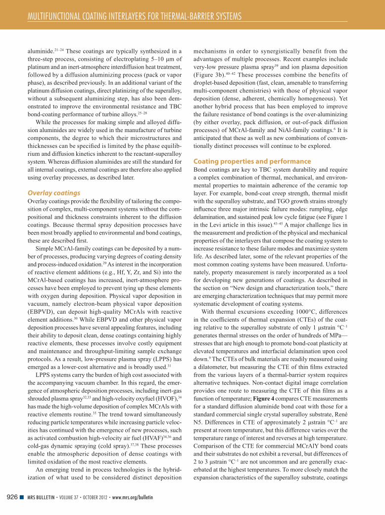
MULTIFUNCTIONAL COATING INTERLAYERS FOR THERMAL-BARRIER SYSTEMS
926 MRS BULLETIN • VOLUME 37 • OCTOBER 2012 • www.mrs.org/bulletin
aluminide. 21 – 24 These coatings are typically synthesized in a
three-step process, consisting of electroplating 5–10 μ m of
platinum and an inert-atmosphere interdiffusion heat treatment,
followed by a diffusion aluminizing process (pack or vapor
phase), as described previously. In an additional variant of the
platinum diffusion coatings, direct platinizing of the superalloy,
without a subsequent aluminizing step, has also been dem-
onstrated to improve the environmental resistance and TBC
bond-coating performance of turbine alloys. 25 – 28
While the processes for making simple and alloyed diffu-
sion aluminides are widely used in the manufacture of turbine
components, the degree to which their microstructures and
thicknesses can be specifi ed is limited by the phase equilib-
rium and diffusion kinetics inherent to the reactant-superalloy
system. Whereas diffusion aluminides are still the standard for
all internal coatings, external coatings are therefore also applied
using overlay processes, as described later.
Overlay coatings Overlay coatings provide the fl exibility of tailoring the compo-
sition of complex, multi-component systems without the com-
positional and thickness constraints inherent to the diffusion
coatings. Because thermal spray deposition processes have
been most broadly applied to environmental and bond coatings,
these are described fi rst.
Simple MCrAl-family coatings can be deposited by a num-
ber of processes, producing varying degrees of coating density
and process-induced oxidation. 29 As interest in the incorporation
of reactive element additions (e.g., Hf, Y, Zr, and Si) into the
MCrAl-based coatings has increased, inert-atmosphere pro-
cesses have been employed to prevent tying up these elements
with oxygen during deposition. Physical vapor deposition in
vacuum, namely electron-beam physical vapor deposition
(EBPVD), can deposit high-quality MCrAls with reactive
element additions. 30 While EBPVD and other physical vapor
deposition processes have several appealing features, including
their ability to deposit clean, dense coatings containing highly
reactive elements, these processes involve costly equipment
and maintenance and throughput-limiting sample exchange
protocols. As a result, low-pressure plasma spray (LPPS) has
emerged as a lower-cost alternative and is broadly used. 31
LPPS systems carry the burden of high cost associated with
the accompanying vacuum chamber. In this regard, the emer-
gence of atmospheric deposition processes, including inert-gas
shrouded plasma spray 32 , 33 and high-velocity oxyfuel (HVOF), 34
has made the high-volume deposition of complex MCrAls with
reactive elements routine. 35 The trend toward simultaneously
reducing particle temperatures while increasing particle veloc-
ities has continued with the emergence of new processes, such
as activated combustion high-velocity air fuel (HVAF) 34 , 36 and
cold-gas dynamic spraying (cold spray). 37 , 38 These processes
enable the atmospheric deposition of dense coatings with
limited oxidation of the most reactive elements.
An emerging trend in process technologies is the hybrid-
ization of what used to be considered distinct deposition
mechanisms in order to synergistically benefit from the
advantages of multiple processes. Recent examples include
very-low pressure plasma spray 39 and ion plasma deposition
( Figure 3b ). 40 – 42 These processes combine the benefits of
droplet-based deposition (fast, clean, amenable to transferring
multi-component chemistries) with those of physical vapor
deposition (dense, adherent, chemically homogeneous). Yet
another hybrid process that has been employed to improve
the failure resistance of bond coatings is the over-aluminizing
(by either overlay, pack diffusion, or out-of-pack diffusion
processes) of MCrAl-family and NiAl-family coatings. 6 It is
anticipated that these as well as new combinations of conven-
tionally distinct processes will continue to be explored.
Coating properties and performance Bond coatings are key to TBC system durability and require
a complex combination of thermal, mechanical, and environ-
mental properties to maintain adherence of the ceramic top
layer. For example, bond-coat creep strength, thermal misfi t
with the superalloy substrate, and TGO growth strains strongly
infl uence three major intrinsic failure modes: rumpling, edge
delamination, and sustained peak low cycle fatigue (see Figure 1
in the Levi article in this issue). 43 – 45 A major challenge lies in
the measurement and prediction of the physical and mechanical
properties of the interlayers that compose the coating system to
increase resistance to these failure modes and maximize system
life. As described later, some of the relevant properties of the
most common coating systems have been measured. Unfortu-
nately, property measurement is rarely incorporated as a tool
for developing new generations of coatings. As described in
the section on “New design and characterization tools,” there
are emerging characterization techniques that may permit more
systematic development of coating systems.
With thermal excursions exceeding 1000°C, differences
in the coeffi cients of thermal expansion (CTEs) of the coat-
ing relative to the superalloy substrate of only 1 μ strain °C –1
generates thermal stresses on the order of hundreds of MPa—
stresses that are high enough to promote bond-coat plasticity at
elevated temperatures and interfacial delamination upon cool
down. 9 The CTEs of bulk materials are readily measured using
a dilatometer, but measuring the CTE of thin fi lms extracted
from the various layers of a thermal-barrier system requires
alternative techniques. Non-contact digital image correlation
provides one route to measuring the CTE of thin fi lms as a
function of temperature; Figure 4 compares CTE measurements
for a standard diffusion aluminide bond coat with those for a
standard commercial single crystal superalloy substrate, René
N5. Differences in CTE of approximately 2 μ strain °C –1 are
present at room temperature, but this difference varies over the
temperature range of interest and reverses at high temperature.
Comparison of the CTE for commercial MCrAlY bond coats
and their substrates do not exhibit a reversal, but differences of
2 to 3 μ strain °C –1 are not uncommon and are generally exac-
erbated at the highest temperatures. To more closely match the
expansion characteristics of the superalloy substrate, coatings

MULTIFUNCTIONAL COATING INTERLAYERS FOR THERMAL-BARRIER SYSTEMS
927MRS BULLETIN • VOLUME 37 • OCTOBER 2012 • www.mrs.org/bulletin
with the same phase constituents ( γ ′ and γ phases) with more
optimal compositions for oxidation have been investigated. 46 – 48
Beyond CTE matching, these systems are desirable due to the
lowered driving forces for interdiffusion. However, a drawback
is the lower amount of Al available in the coating “reservoir”
for TGO formation.
The mechanical properties of bond coatings have a signifi -
cant infl uence on their durability in service. Diffusion aluminide
coatings have been shown to have a ductile-brittle transition
temperature (DBTT) of approximately 600°C. Below the DBTT,
the bond coat is linearly elastic with a Young’s modulus that
depends on composition and is comparable with what has been
reported for the β -NiAl phase. Above the DBTT, the ultimate
tensile strength and creep response of the diffusion aluminide
bond coat is extremely temperature dependent ( Figure 5 a).
Strengths of 400 MPa have been measured at
intermediate temperatures, but above 1000°C,
the strength of commercial diffusion aluminide
bond coats does not exceed 50 MPa. Attempts
to improve the elevated temperature strength
have been only minimally successful, with the
greatest high temperature strength being asso-
ciated with the development of ruthenium
aluminide bond coats 49 – 51 ( Figure 5a ).
Overlay properties can vary much more
widely than those of the diffusion coatings
since the composition and microstructure can
be more widely varied. Their properties have
been somewhat better characterized, since it
is possible to deposit very thick layers of the
coating (albeit with some loss of similitude of
microstructure) and machine conventionally
sized test specimens. In general, the physical
properties of overlay coatings are similar to
those of conventional superalloys. The thermal
expansion, particularly of coatings containing
Co, tends to be greater than that of superalloys,
which tends to increase thermal stresses in these coatings.
MCrAlY coatings have been reported to be very strong at room
temperature, but their elevated temperature strength is dramati-
cally reduced. Micro-tensile tests of a commercial NiCoCrAlY
coating demonstrate impressive room temperature properties
with an ultimate tensile strength of 1.4 GPa and signifi cant
(>2%) ductility. 52 The strength of these coatings is, however,
very temperature dependent and signifi cantly lower than has
been measured for diffusion aluminide coatings ( Figure 5b ).
During service, incorporation of Al into the TGO and contin-
ued interdiffusion between the coating and underlying substrate
signifi cantly reduces the Al content of the bond coating, which
can result in the formation of metastable L1 0 martensite phase
γ ′ -Ni 3 Al, and eventually γ -Ni. The formation of the L1 0 mar-
tensite can have a dramatic effect on rumpling if the martensitic
(diffusionless) transformation, and attendant volume change,
occurs at intermediate temperatures, where the bond coat is
easily plastically deformed. The martensite start temperature
( M s ) is extremely sensitive to composition and the presence of
Pt, which is a common addition to many commercial diffusion
aluminide coatings. 53 Without Pt, the martensitic transformation
occurs at temperatures well below the β –NiAl DBTT and is
stored and recovered elastically. The addition of Pt raises the
transformation temperature, which promotes plastic deforma-
tion of the bond coat. 54 , 55
The TGO is also a key mechanical element of the multilay-
ered system. The TGO undergoes thickening and elongation
during the lifetime of the system. The thickening increases the
strain energy density, while the elongation provides a driving
force for coating failure via the rumpling mechanism. 54 , 55
TGO elongation results from new TGO forming on internal
grain boundaries, 55 – 57 while thickening is caused by new TGO
forming at the TGO/bond-coat interface. The elongation strain
Figure 4. Coeffi cients of thermal expansion (CTEs) for a
commercial diffusion aluminide (Ni,Pt)Al bond coat and its
generation 3 René N5 Ni-based superalloy.
Figure 5. (a) The tensile strength of a NiCoCrAlY overlay bond coat, a platinum modifi ed
diffusion aluminide bond coat, and a developmental ruthenium aluminide alloy measured and
plotted as a function of temperature. (b) Measured stress relaxations for a diffusion aluminide
bond coat. The rate of relaxation above 600°C is impressive, but the relaxation data have
been shown to follow conventional models for thermally activated power law creep.
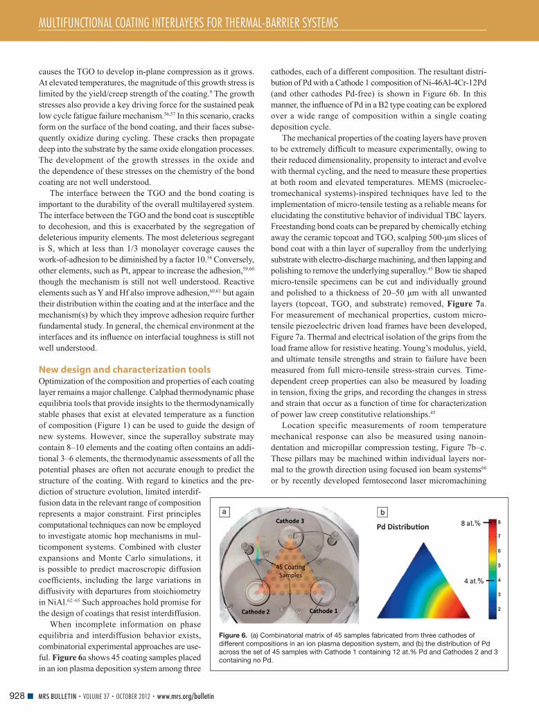
MULTIFUNCTIONAL COATING INTERLAYERS FOR THERMAL-BARRIER SYSTEMS
928 MRS BULLETIN • VOLUME 37 • OCTOBER 2012 • www.mrs.org/bulletin
causes the TGO to develop in-plane compression as it grows.
At elevated temperatures, the magnitude of this growth stress is
limited by the yield/creep strength of the coating. 9 The growth
stresses also provide a key driving force for the sustained peak
low cycle fatigue failure mechanism. 56 , 57 In this scenario, cracks
form on the surface of the bond coating, and their faces subse-
quently oxidize during cycling. These cracks then propagate
deep into the substrate by the same oxide elongation processes.
The development of the growth stresses in the oxide and
the dependence of these stresses on the chemistry of the bond
coating are not well understood.
The interface between the TGO and the bond coating is
important to the durability of the overall multilayered system.
The interface between the TGO and the bond coat is susceptible
to decohesion, and this is exacerbated by the segregation of
deleterious impurity elements. The most deleterious segregant
is S, which at less than 1/3 monolayer coverage causes the
work-of-adhesion to be diminished by a factor 10. 58 Conversely,
other elements, such as Pt, appear to increase the adhesion, 59 , 60
though the mechanism is still not well understood. Reactive
elements such as Y and Hf also improve adhesion, 60 , 61 but again
their distribution within the coating and at the interface and the
mechanism(s) by which they improve adhesion require further
fundamental study. In general, the chemical environment at the
interfaces and its infl uence on interfacial toughness is still not
well understood.
New design and characterization tools Optimization of the composition and properties of each coating
layer remains a major challenge. Calphad thermodynamic phase
equilibria tools that provide insights to the thermodynamically
stable phases that exist at elevated temperature as a function
of composition ( Figure 1 ) can be used to guide the design of
new systems. However, since the superalloy substrate may
contain 8–10 elements and the coating often contains an addi-
tional 3–6 elements, the thermodynamic assessments of all the
potential phases are often not accurate enough to predict the
structure of the coating. With regard to kinetics and the pre-
diction of structure evolution, limited interdif-
fusion data in the relevant range of composition
represents a major constraint. First principles
computational techniques can now be employed
to investigate atomic hop mechanisms in mul-
ticomponent systems. Combined with cluster
expansions and Monte Carlo simulations, it
is possible to predict macroscropic diffusion
coeffi cients, including the large variations in
diffusivity with departures from stoichiometry
in NiAl. 62 – 65 Such approaches hold promise for
the design of coatings that resist interdiffusion.
When incomplete information on phase
equilibria and interdiffusion behavior exists,
combinatorial experimental approaches are use-
ful. Figure 6 a shows 45 coating samples placed
in an ion plasma deposition system among three
cathodes, each of a different composition. The resultant distri-
bution of Pd with a Cathode 1 composition of Ni-46Al-4Cr-12Pd
(and other cathodes Pd-free) is shown in Figure 6b . In this
manner, the infl uence of Pd in a B2 type coating can be explored
over a wide range of composition within a single coating
deposition cycle.
The mechanical properties of the coating layers have proven
to be extremely diffi cult to measure experimentally, owing to
their reduced dimensionality, propensity to interact and evolve
with thermal cycling, and the need to measure these properties
at both room and elevated temperatures. MEMS (microelec-
tromechanical systems)-inspired techniques have led to the
implementation of micro-tensile testing as a reliable means for
elucidating the constitutive behavior of individual TBC layers.
Freestanding bond coats can be prepared by chemically etching
away the ceramic topcoat and TGO, scalping 500- μ m slices of
bond coat with a thin layer of superalloy from the underlying
substrate with electro-discharge machining, and then lapping and
polishing to remove the underlying superalloy. 45 Bow tie shaped
micro-tensile specimens can be cut and individually ground
and polished to a thickness of 20–50 μ m with all unwanted
layers (topcoat, TGO, and substrate) removed, Figure 7 a.
For measurement of mechanical properties, custom micro-
tensile piezoelectric driven load frames have been developed,
Figure 7a . Thermal and electrical isolation of the grips from the
load frame allow for resistive heating. Young’s modulus, yield,
and ultimate tensile strengths and strain to failure have been
measured from full micro-tensile stress-strain curves. Time-
dependent creep properties can also be measured by loading
in tension, fi xing the grips, and recording the changes in stress
and strain that occur as a function of time for characterization
of power law creep constitutive relationships. 45
Location specific measurements of room temperature
mechanical response can also be measured using nanoin-
dentation and micropillar compression testing, Figure 7b–c .
These pillars may be machined within individual layers nor-
mal to the growth direction using focused ion beam systems 66
or by recently developed femtosecond laser micromachining
Figure 6. (a) Combinatorial matrix of 45 samples fabricated from three cathodes of
different compositions in an ion plasma deposition system, and (b) the distribution of Pd
across the set of 45 samples with Cathode 1 containing 12 at.% Pd and Cathodes 2 and 3
containing no Pd.

MULTIFUNCTIONAL COATING INTERLAYERS FOR THERMAL-BARRIER SYSTEMS
929MRS BULLETIN • VOLUME 37 • OCTOBER 2012 • www.mrs.org/bulletin
methods. 67 , 68 A well-developed methodology of compressing
these pillars with fl at diamond microindentors 66 permits acqui-
sition of room temperature properties of the coatings. With size-
scale effects properly accounted for, these techniques provide
location specifi c measures of modulus, hardness, and strength,
but they are currently limited to room temperature measurement.
Other location-specifi c measurements for properties such as
thermal conductivity have also recently been developed. 69 , 70 Pros-
pects for intermediate temperature testing are promising, but these
techniques are far from being used at temperatures of 1000°C.
As mentioned previously, the TGO, typically alumina, is
a key element of the multilayered system that must adhere to
the bond coating to provide an environmental barrier and to
maintain adherence of the ceramic topcoat. Optical spectros-
copy tools offer non-contact, non-destructive evaluation of the
state of the TGO during cycling. 71 – 75 Luminescence lines gener-
ated by laser illumination undergo a stress-induced frequency
shift due to the presence of very small quantities of naturally
occurring Cr 3+ as an impurity. Analysis of the luminescence
spectrum permits assessment of the stresses in the TGO, which
are compressive and of the order of 100–400 MPa at elevated
temperature and rise beyond 4 GPa at room temperature due
to the CTE mismatch with the superalloy substrate. 57 , 77 , 78 With
recently incorporated scanning capabilities, new piezospec-
troscopy tools can analyze the spatial variations in stress as
well as assess subsurface damage that alters the stress state in
the oxide. 73 – 76 An example of the spatial variation in stresses is
shown for a platinum aluminide coating oxidized at 1093°C,
Figure 8 , where the compressive stresses in the oxide range
from 3–7 GPa following cooling to room temperature. Syn-
chrotron x-ray experiments have additionally been employed
to observe the development and evolution of growth stresses
in situ at elevated temperatures. 77 , 78
Future challenges and opportunities Building the infrastructure to design multicomponent bond
coatings that perform in a predictable manner within the multi-
layered thermal-barrier coating (TBC) system remains a major
challenge. The bond-coat element of the TBC system has tradi-
tionally been developed in isolation from the substrate and the
ceramic topcoat with limited measurement of properties as a
function of composition. This can lead to substantial debits in
performance when combined with system elements. Emerging
Figure 7. (a) Freestanding diffusion aluminide bond coat micro-tensile specimen mounted in a custom build load frame, resistively heated
and ready for tensile testing, (b) micropillar machined with femtosecond laser, and (c) a series of micropillars machined across a coating
interface.
Figure 8. Stresses in a PtAl coating after oxidation at 1093°C
/160 h and subsequent cooling to room temperature measured
by confocal piezospectroscopy.

MULTIFUNCTIONAL COATING INTERLAYERS FOR THERMAL-BARRIER SYSTEMS
930 MRS BULLETIN • VOLUME 37 • OCTOBER 2012 • www.mrs.org/bulletin
tools with improved capabilities for predicting and measuring
properties, some described in the previous sections and some
yet to be developed, will contribute positively to this challenge.
The properties of interfaces within the system remain as a
barrier to predicting system performance.
The drive toward higher-effi ciency (i.e., hotter-running,
more highly stressed) engines, unconventional propulsion fuels,
and reduced reliance on exotic materials will motivate these
new tools for optimizing system performance as well as new
coatings with the following characteristics:
• Multi-component coatings for turbine parts with internal
passages that are not amenable to line-of-sight overlay
coating processes
• Multi-functional coatings capable of location-specific
response
• Coatings that possess load-bearing capability, which are
increasingly important as aero components move to thinner
walls
• Coating processes that are amenable to fi eld application
(e.g., high-agility thermal spray processes that can be
employed for localized repair)
• Reduced cost coatings that contain limited amounts of Pt
and other costly/scarce materials that can be applied with
low-capital processing equipment, fl exible chemistry, and
simplifi cation of manufacturing processes (fewer process
steps, scalable equipment, low maintenance).
Finally, with regard to system performance, experience with
existing bond-coat/TBC systems has illustrated a competition
between failure mechanisms that depend strongly on the plastic
properties of the bond coat, the interface fracture toughness
governing bond coat/TGO or TGO/TBC failure, and the fracture
toughness of the ceramic topcoat. 2 , 8 , 9 In order to speed system
development and deployment, simulations are needed to help
anticipate such competitions and identify material combina-
tions that balance multiple failure mechanisms. Conventional
approaches to simulate interface and coating failure processes
are not well suited to this task because they require explicit
a priori defi nition of the failure mode, including multiple crack
geometries, computation of the associated energy release rates,
and the post- priori assessment of stability (by comparing driving
forces to toughness). Coupled with the need to conduct simula-
tions for a broad material parameter space, there is a critical need
for an effi cient alternative approach that reduces the number of
simulations required to identify active failure mechanisms in
terms of system properties. Parallel computing approaches are
likely to advance these systems-based challenges.
Acknowledgments T.P. is grateful for the support of an NSF-GOALI program
DMR-11–05672.
References 1. R.C. Reed , The Superalloys: Fundamentals and Applications ( Cambridge University Press , UK , 2006 ). 2. A.G. Evans , D.R. Clarke , C.G. Levi , J. Eur. Ceram. Soc. 28 ( 7 ), 1405 ( 2008 ). 3. S.M. Meier , D.K. Gupta , Trans. ASME 116 , 250 ( 1994 ).
4. U. Schulz , C. Leyens , K. Fritscher , M. Peters , B. Saruhan-Brings , O. Lavigne , M. Dorvaux , M. Poulain , R. Mévrel , M.L. Caliez , Aerosp. Sci. Technol. 7 ( 1 ), 73 ( 2003 ). 5. T. DeMasi-Marcin , D.K. Gupta , Surf. Coat. Technol. 68/69 , 1 ( 1994 ). 6. J.R. Nicholls , MRS Bulletin 28 , 659 , ( 2003 ). 7. M.J. Stiger , N.M. Yanar , M. Topping , F.S. Pettit , G.H. Meier , Z. Metallkd. 90 , 1069 ( 1999 ). 8. P.K. Wright , A.G. Evans , Curr. Opin. Solid State Mater. Sci. 4 , 255 ( 1999 ). 9. A.G. Evans , D.R. Mumm , J.W. Hutchinson , G.H. Meier , F.S. Pettit , Prog. Mater Sci. 46 , 505 ( 2001 ). 10. R.T. Wu , K. Kawagishi , H. Harada , R.C. Reed , Acta Mater. 14 , 3622 ( 2008 ). 11. J.G. Smeggil , A.W. Funkenbush , N.S. Bornstein , Metall. Trans. A 17 , 923 ( 1986 ). 12. J.L. Smialek , in Microscopy of Oxidation 3 , S.B. Newcomb , J.A. Little , Eds. ( The Institute of Materials , London, UK , 1996 ), p. 127 . 13. P.Y. Hou , Oxid. Met. 52 , 337 ( 1999 ). 14. I.G. Wright , B.A. Pint , W.Y. Lee , K.B. Alexander , K. Prüssner , in High Temperature Surface Engineering ( The Institute of Materials , London, UK , 2000 ), p. 95 . 15. G.W. Goward , L.W. Cannon , ASME Paper 87-GT-50 ( ASME , New York , 1988 ). 16. G.M.C.A. Gauje , US Patent 3,486,927 ( 1969 ). 17. D.J. Levine , M.A. Levinstein , US Patent 3,540,878 ( 1970 ). 18. D.J. Levine , US Patent No. 3,598,638 ( 1971 ). 19. R.L. Wachtell , C.A. De Guisto , US Patent No. 3,073,015 ( 1963 ). 20. R. Bianco , R.A. Rapp , J. Electrochem. Soc. 140 ( 4 ), 1181 ( 1993 ). 21. R.G. Wing , I.R. McGill , Platinum Met. Rev. 25 ( 3 ), 94 ( 1981 ). 22. J.S. Smith , D.H. Boone , ASME Paper 90-GT-319 ( ASME , 1990 ). 23. P.C. Patnaik , R. Thamburaj , T.S. Sudarshan , in Surface Modifi cation Technologies III , T.S. Sudarshan , D.G. Bhat , Eds. ( TMS , Warrendale, PA , 1990 ), p. 759 . 24. T.E. Strangman , US Patent 5,514,482 ( 1996 ). 25. I.R. McGill , G.L. Selman , US Patent 4,399,199 ( 1983 ). 26. G.J. Tatlock , T.J. Hurd , Oxid. Met. 22 , 201 ( 1984 ). 27. B.A. Nagaraj , W.B. Connor , R.W. Jendrix , D.J. Wortman , L.W. Plemmons , US Patent 5,427,866 ( 1995 ). 28. D.S. Rickerby , S.R. Bell , R.G. Wing , US Patent 5,667,663 ( 1997 ). 29. S. Sampath , X.Y. Jiang , J. Matejicek , L. Prchlik , A. Kulkarni , A. Vaidya , Mater. Sci. Eng., A 364 , 216 ( 2004 ). 30. D.H. Boone , S. Shen , R. McKoon , Thin Solid Films 64 ( 2 ), 299 ( 1979 ). 31. S. Shankar , D.E. Koenig , L.E. Dardi , J. Met. 33 ( 10 ), 13 ( 1981 ). 32. J.E. Jackson , US Patent No. 3,470,347 ( 1969 ). 33. T.A. Taylor , M.P. Overs , B.J. Gill , R.C. Tucker , J. Vac. Sci. Technol., A 3 ( 6 ), 2526 ( 1985 ). 34. J.A. Browning , US Patent 5,120,582 ( 1992 ). 35. L. Russo , M. Dorfman , in Proceedings of the International Thermal Spray Conference , A. Ohmori , Ed. ( High-Temperature Society of Japan , 2002 ), p. 1179 . 36. V. Baranovski , A. Verstak , US Patent 6,245,390 ( 2001 ). 37. T. Stoltenhoff , H. Kreye , H.J. Richter , J. Therm. Spray Technol. 11 ( 4 ), 542 ( 2002 ). 38. Y. Ichikawa , K. Sakaguchi , K. Ogawa , T. Shoji , S. Barradas , M. Jeandin , M. Boustie , in Thermal Spray 2007: Global Coating Solutions , B.R. Marple , M.M. Hyland , Y.-C. Lau , C.-J. Li , R.S. Lima , G. Montavon , Eds. ( ASM International , Materials Park, OH , 2007 ), p. 54 . 39. M.F. Smith , A.C. Hall , J.D. Fleetwood , P. Meyer , Coatings 1 , 117 ( 2011 ). 40. E.N. Kablov , S.A. Muboyadzhyan , S.A. Budinovskii , A.N. Lutsenko , Russ. Metall. 5 , 364 ( 2007 ). 41. J. Vetter , O. Knotek , J. Brand , W. Beele , Surf. Coat. Technol. 68 – 69 , 27 ( 1994 ); O. Knotek, E. Lugscheider, F. Löffl er, W. Beele, C. Barimani, Surf. Coat. Technol. 74–75 , 118(1995) . 42. J.-C. Zhao , D.M. Lipkin , US Patent 6,964,791 ( 2005 ). 43. D.S. Balint , J.W. Hutchinson , Acta Mater. 51 , 3965 ( 2003 ). 44. D.S. Balint , J.W. Hutchinson , J. Mech. Phys. Solids 53 , 949 ( 2005 ). 45. D. Pan , M.W. Chen , P.K. Wright , K.J. Hemker , Acta Mater. 51 , 2205 ( 2003 ). 46. I. Takeshi , B. Gleeson , J. Jpn. Inst. Met. 71 , 34 ( 2007 ). 47. A. Sato , H. Harada , K. Kawagishi , Metall. Mater. Trans. A 37 , 790 ( 2006 ). 48. K. Kawagishi , H. Harada , A. Sato , K. Matsumoto , Superalloys 76 ( 2008 ). 49. B. Tryon , F. Cao , K.S. Murphy , C.G. Levi , T.M. Pollock , JOM 58 , 53 ( 2006 ). 50. B. Tryon , Q. Feng , R. Wellman , K. Murphy , J. Yang , C. Levi , J. Nicholls , T.M. Pollock , Metall. Mater. Trans. A 37 , 3347 ( 2006 ). 51. F. Cao , T.M. Pollock , Metall. Mater. Trans. A 39 , 39 ( 2008 ). 52. K.J. Hemker , B.G. Mendis , C. Eberl , Mater. Sci. Eng., A 483 – 484 , 727 ( 2008 ). 53. M.W. Chen , M.L. Glynn , R.T. Ott , T.C. Hufnagel , K.J. Hemker , Acta Mater. 51 , 4279 ( 2003 ). 54. A.M. Karlsson , J.W. Hutchinson , A.G. Evans , Mater. Sci. Eng., A 351 , 24 ( 2003 ). 55. D.R. Mumm , A.G. Evans , I.T. Spitsberg , Acta Mater. 49 , 2329 ( 2001 ).

MULTIFUNCTIONAL COATING INTERLAYERS FOR THERMAL-BARRIER SYSTEMS
931MRS BULLETIN • VOLUME 37 • OCTOBER 2012 • www.mrs.org/bulletin
56. A. Suzuki , M.F.X. Gigliotti , B.T. Hazel , D.G. Konitzer , T.M. Pollock , Metall. Mater. Trans. A 41 , 948 ( 2010 ). 57. A.G. Evans , M.Y. He , A. Suzuki , M. Gigliotti , B. Hazel , T.M. Pollock , Acta Mater. 57 , 2969 ( 2009 ). 58. W. Zhang , J.R. Smith , X.-G. Wang , A.G. Evans , Phys. Rev. B 67 ( 245414 ), 1 ( 2003 ). 59. B.A. Pint , I.G. Wright , W.Y. Lee , Y. Zhang , K. Prüßner , K.B. Alexander , Mater. Sci. Eng., A 245 , 201 ( 1998 ). 60. B. Pint , J.A. Haynes , T.M. Besmann , Surf. Coat. Technol. 204 , 3287 ( 2010 ). 61. J.L. Smialek , in Proc. Electrochemical Society: Symposium on High Temperature Corrosion and Materials Chemistry , P.Y. Hou , M.J. McNallan , R. Oltra , E.J. Opila , D.A. Shores , Eds. ( Electrochemical Society , Pennington, NJ , 1998 ), pp. 211 – 220 . 62. Q. Xu , A. Van der Ven , Acta Mater. 59 , 1095 ( 2011 ). 63. A. Van der Ven , J.C. Thomas , Q. Xu , J. Bhattacharya , Math. Comput. Simul. 80 ( 7 ), 1393 ( 2010 ). 64. Q. Xu , A. Van der Ven , Phys. Rev. B 81 , 064303 ( 2010 ). 65. Q. Xu , A. Van der Ven , Intermetallics 17 ( 5 ), 319 ( 2009 ).
66. M.D. Uchic , D.M. Dimiduk , J.N. Florando , W.D. Nix , Science 305 , 986 ( 2004 ). 67. Q. Feng , Y.N. Picard , H. Liu , S.M. Yalisove , G. Mourou , T.M. Pollock , Scripta Mater. 53 , 511 ( 2005 ). 68. S. Ma , B. Tryon , J.P. McDonald , S.M. Yalisove , T.M. Pollock , Metall. Mater. Trans. A 38 , 2153 ( 2007 ). 69. X. Zheng , D.G. Cahill , R. Weaver , J.-C. Zhao , J. Appl. Phys. 104 , 073509 ( 2008 ). 70. J.-C. Zhao , Prog. Mater Sci. 51 , 557 ( 2006 ). 71. S.H. Margueron , D.R. Clarke , Acta Mater. 54 , 5551 ( 2006 ). 72. D.R. Clarke , D.J. Gardiner , Int. J. Mater. Res. 98 , 8 ( 2007 ). 73. V.K. Tolpygo , D.R. Clarke , K.S. Murphy , Surf. Coat. Technol. 188 – 189 , 62 ( 2004 ). 74. D.R. Clarke , Curr. Opin. Solid State Mater. Sci. 6 , 237 ( 2002 ). 75. V. Sergo , D.R. Clarke , J. Am. Ceram. Soc. 81 , 3237 ( 1998 ). 76. V.K. Tolpygo , J.R. Dryden , D.R. Clarke , Acta Mater. 46 , 927 ( 1998 ). 77. P.Y. Hou , A.P. Paullikas , B.W. Veal , Mater. Sci. Forum 522 – 523 , 433 ( 2006 ). 78. D. Hovis , L. Hu , A. Reddy , A.H. Heuer , A.P. Paullikas , B.W. Veal , Int. J. Mater. Res. 98 , 12 ( 2007 ).
Unique in several ways, the Foundation:
advances the MRS mission to “promote communication
for the advancement of interdisciplinary materials
research to improve the quality of life”
focuses on member engagement and funding to enrich,
expand and ensure MRS core programs in education,
outreach and peer recognition
leverages corporate partner, institutional and individual
support to invest in projects of importance to the materials
community, as defined by the materials community
benefits a wide range of innovative grassroots, member-
driven initiatives—from student chapter proposals, to
local or regional education/outreach projects, to those
with the potential to impact the materials enterprise
worldwide.
To learn how you can help make a difference or to apply
for project funding, explore the Foundation website,
www.mrs.org/foundation. The first project grants will be
awarded at the 2013 MRS Spring Meeting in San Francisco.
The Materials Research Society Foundation operates as a program of the Materials Research Society.
The official registration and financial information of the Materials Research Society Foundation may
be obtained from the Pennsylvania Department of State by calling toll free, within Pennsylvania,
1.800.732.0999. Registration does not imply endorsement.
The Materials Research Society
is proud to announce the

932 MRS BULLETIN • VOLUME 37 • OCTOBER 2012 • www.mrs.org/bulletin © 2012 Materials Research Society
Introduction The degradation of thermal-barrier coatings (TBCs) by molten
deposits resulting from a combination of impurities introduced
with the intake air and/or the fuel has been a concern since
the introduction of these material systems in gas turbines.
Corrosion by molten salts, especially alkaline sulfate-vanadate
mixtures, was of early interest owing to (1) their potential for
de-stabilization of the non-transformable, metastable tetragonal
yttria-stabilized zirconia ( t’ -YSZ) 1–3 commonly used as a topcoat
material and (2) their possible infi ltration toward the thermally
grown oxide (TGO) because their melting point is below the
temperature of the TGO/TBC interface (see the Introductory
article in this issue for a more detailed description of TBC
structure). The latter could have two consequences, one
related to a chemical attack of the TGO/bond coat, 4 and the
other associated with freezing of the salt within the TBC on
cooling and the ensuing loss of strain tolerance. 5 Phenomeno-
logical models have been developed to assess the effects of
sulfate infi ltration on coating life, 6 and promising materials
solutions have been proposed. 7–9 However, currently adopted
solutions rely primarily on fuel quality control.
As noted elsewhere in this issue, coatings are now enabling
to the design of advanced gas turbines, whether based on
metallic or ceramic components, with current goals calling for
material surface temperatures ≥ 1500°C. 10 While low melting
temperature salts remain a problem in some TBC applications,
they do not constitute a fundamental barrier to increased per-
formance, because the projected elevation in gas temperature
would be above the dew point of most sulfate/vanadate salts.
In contrast, the severe threat of silicate deposits at higher tem-
perature operation was recognized quite early. 11–13 The problem
arises from the ingestion of siliceous debris (airborne dust, sand,
ash) that adheres to the surfaces in the hot gas path (combustors,
airfoils, shrouds) and at peak temperatures of the engine cycle
(e.g., take-off or landing) yields glassy melts based on calcium-
magnesium alumino-silicates (CMAS). The glass wets all
coating materials of interest and can (1) penetrate the TBC
void spaces that accommodate the strain incompatibility with
the metallic substrate and/or (2) chemically dissolve the coat-
ing material, usually followed by precipitation of a modifi ed
oxide. 12–16 Because all prospective TBCs have to be porous/
segmented to render them strain-tolerant and most silicate
deposits melt around 1200°C, 12,13,17,18 any increases in operating
temperature needed to enhance turbine effi ciency would require
fi nding solutions to the CMAS problem. These deposits and
the associated degradation of TBCs are therefore the primary
focus of this article.
This article is organized into three main sections. The fi rst
section discusses the thermomechanical problem and the asso-
ciated driving forces. The second addresses thermochemical
Environmental degradation of thermal-barrier coatings by molten deposits Carlos G. Levi , John W. Hutchinson , Marie-Hélène Vidal-Sétif , and Curtis A. Johnson
Molten deposits based on calcium-magnesium alumino-silicates (CMAS), originating from
siliceous debris ingested with the intake air, represent a fundamental threat to progress in
gas turbine technology by limiting the operating surface temperature of coated components.
The thermomechanical and thermochemical aspects of the CMAS interactions with thermal-
barrier coatings, as well as the current status of mitigating strategies, are discussed in
this article. Key challenges and research needs for developing adequate solutions are
highlighted.
Carlos G. Levi, Materials Department , University of California , Santa Barbara ; [email protected] John W. Hutchinson, School of Engineering and Applied Sciences , Harvard University ; [email protected] Marie-Hélène Vidal-Sétif, Department of Metallic Materials and Structures , Onera , French Aerospace Lab ; [email protected] Curtis A. Johnson, GE Global Research and Center for Thermal Spray Research , Stony Brook University ; [email protected] DOI: 10.1557/mrs.2012.230

ENVIRONMENTAL DEGRADATION OF THERMAL-BARRIER COATINGS BY MOLTEN DEPOSITS
933MRS BULLETIN • VOLUME 37 • OCTOBER 2012 • www.mrs.org/bulletin
issues, which lead to opportunities for mitigation. The third
deals with the experimental evaluation of the mitigation
approaches. It fi nishes with a brief outlook on critical research
needs.
Thermomechanical aspects CMAS related damage mechanisms and field evidence The TBC failure mechanisms identifi ed to date are illustrated in
Figure 1 . While the role of CMAS is viewed primarily in terms
of stiffening of the top t’- YSZ coat leading to shallow or deep
delaminations, 13 , 20 , 21 recent work has shown that CMAS contact
with the TGO results in chemical interactions and subsequent
delamination along the TGO 22 or may promote creep cavitation
in the bond coat wherein the delamination crack path would
propagate within the metal, rather than the ceramic layers. 23
As turbine temperatures continue to increase, existing mecha-
nisms will be aggravated, and new forms of damage may arise.
Moreover, CMAS infi ltration leads not only to stiffening of the
coating, but also to degradation of the insulating properties of
the TBC, 24 , 25 which may aggravate other intrinsic but nominally
unrelated forms of degradation (e.g., rumpling 26 ). The challenge
of coating life prediction thus acquires new dimensions in the
presence of CMAS.
An example of CMAS damage on current airfoils is
depicted in Figure 2 (left side) corresponding to state-of-
the-art t’- YSZ TBCs in a commercial aircraft engine. While
the thermal history cannot be ascertained, it is known that the
engine operated short fl ights (i.e., frequent cycles with sub-
stantial hot periods) in dusty environments. 27 The distress is
quite evident, extending beyond TBC loss to affect the TGO
and bond coat, in some places exposing the base metal. (The
coating on the right side of Figure 2 is discussed later in
the text.)
Delamination damage due to CMAS has been studied
in both commercial and military aircraft engines and exhibits
common features in coatings produced by electron-beam physi-
cal vapor deposition (EBPVD) 20 as well as dense, vertically
cracked TBCs produced by atmospheric plasma spray (APS). 21
In areas where the coating was cracked but not yet lost, the level
Figure 1. Extended menu of failure mechanisms typical of current thermal-barrier coatings (TBCs). 19 Three general modes of CMAS
damage (lower right), characteristic of higher temperature operation, have been identifi ed so far. One involves delamination cracks
propagating through the TBC, another leads to chemical attack of the thermally grown oxide (TGO) with concomitant loss of adherence,
and a third results from creep cavitation of the bond coat below a heavily penetrated TBC. FOD, foreign object damage; da/dN, crack
growth per cycle; du/dN, inward displacement of TGO per cycle.
Figure 2. Comparison of typical distress experienced by
conventional thermal-barrier coatings (TBCs) based on
7–8% yttria-stabilized zirconia with an advanced TBC based on
Gd x Zr 1– x O 2– x /2 pyrochlore, where x ≈ 0.5. The airfoils were part
of an engine test in actual aircraft operation. 26 Courtesy of
M.J. Maloney, Pratt & Whitney.

ENVIRONMENTAL DEGRADATION OF THERMAL-BARRIER COATINGS BY MOLTEN DEPOSITS
934 MRS BULLETIN • VOLUME 37 • OCTOBER 2012 • www.mrs.org/bulletin
of CMAS penetration was about one-half of the total thickness,
but deeper penetrations have been found in other airfoils. The
driving forces behind these failures are now examined briefl y.
Understanding the driving force for thermo-mechanical failure Release of the elastic strain energy stored in the coating supplies
the underlying driving force for the delamination and spalling
of TBC coatings. 28 The major source of this elastic energy is the
thermal expansion mismatch between the coating and the metal
substrate that occurs upon cooling. To facilitate understanding
of the origin of this elastic energy, the following discussion will
focus fi rst on isothermal cooling of the TBC/substrate system
and then consider more representative scenarios involving
a thermal gradient through the system in the hot state and
transient cooling.
Stress in the coatings is relaxed by creep at high tempera-
tures, and, thus, a reasonable working assumption is that
the coating stresses are zero at the hottest operating state. Cool-
down is relatively rapid, such that in most instances, one may
assume that thermoelastic behavior applies with no further
creep relaxation. Clear insights into the coating stress and elas-
tic energy emerge from a model that views the substrate as
thick and at uniform temperature. 28 The substrate constrains
bending, which is taken to vanish in the model and imposes an
in-plane biaxial strain change, – α s Δ T sub , on the coating. Here,
α s is the thermal expansion coeffi cient of the substrate and,
during cooling, 0
sub sub subT T TΔ = − is the temperature drop of
the substrate from its temperature in the hot state, 0
subT . For
simplicity, the coeffi cients of thermal expansion will be taken
to be temperature-independent. In the hot state, a steady-state
temperature distribution exists with 0
surT at the coating surface
and 0
subT at its interface with the substrate. The temperature
drop of the coating surface relative to the substrate is denoted
by ( )0
sur / sub sur sur subT T T TΔ = − − Δ .
Consider a single layer uniform coating with Young’s
modulus, E c , Poisson’s ratio, ν c , coeffi cient of thermal expan-
sion, α c , and thickness, h c . At any stage during cool-down,
idealize the temperature distribution in the coating to be linear
according to
( ) ( )sub C sur / suby y / ,T T TΔ = Δ + Δh (1)
with y as the through-thickness coordinate measured from the
interface. At any stage during cool-down, the state of stress in
the layer is equibiaxial, in-plane, given by
( ) ( )( )sub sur / suby y / .1
ET Tσ = −Δα Δ + α Δ
− νhC
C C CC
(2)
This equation reveals that cooling of the coating relative
to the substrate generates tensile stress depending on the full
coeffi cient of thermal expansion of the coating, while cooling
of the substrate imposes stress on the coating depending on the
thermal expansion mismatch, Δ α c = α S – α c . The elastic energy
per area in the coating associated with these thermal stresses,
available for release of the coating from the substrate under
plane strain conditions, is
2C C C
C sub C sub C sur / sub
C
2
C sur / sub
1
2 1
1.
3
U T T T
T
να α α
ν
α
E h
(3)
The interaction term, ( )( )C sub C sur / subT TΔα Δ α Δ , is important,
and it arises because the compressive coating stress driven
by cooling of the substrate, Δ T sub , can be offset by the tensile
stress associated with cooling of the coating surface relative
to the substrate, Δ T sur/sub . For the calculations shown here,
α C = 11 × 10 –6 C –1 , α S = 13 × 10 –6 C –1 , and the coating’s Poisson’s
ratio is ν c = 0.2.
The elastic energy/unit area given by Equation 3 is plotted in
normalized form ( U/E c h c ) in Figure 3 . Two limiting scenarios
are insightful. The fi rst applies when the coating and substrate
have a uniform temperature both in the hot state and while
cooled (i.e., Δ T sub increases while Δ T sur/sub = 0). This is repre-
sentative of furnace cycle tests involving isothermal holds and
relatively slow-cooling. Given that U scales with h c and con-
sidering a typical in-plane modulus absent CMAS penetration,
E c = 30 GPa, a “thin” 200 μ m TBC illustrative of aero-engine
blades would build up an elastic energy of ∼ 11 J·m –2 on cool-
ing from 0
sub800 CT = ° , whereas a “thick” 1-mm coating that
might be found in power generation components would reach
∼ 58 J·m –2 under the same conditions. Whether failure would
occur depends, of course, on the coating toughness under the
pertinent crack propagation mode, which is not well charac-
terized for these systems.
Consider now the case where the TBC is stiffened by com-
plete penetration of CMAS, elevating the Young’s modulus to
at least that of typical glasses (i.e., E c = 90 GPa). (Higher values
are likely given that most of the coating is dense t’- YSZ, with
E YSZ ≈ 200 GPa.) The elastic energy accumulated in the same
thermal excursion for the representative “thin” and “thick”
coatings cited previously would then go up by a factor of 3, to
∼ 35 and ∼ 173 J·m –2 , respectively. This simple result gives the
clearest insight into the role CMAS plays in debilitating a TBC
by degrading its in-plane compliance. CMAS infi ltration also
alters other properties of the coating such as the coeffi cient of
thermal expansion and the thermal conductivity, 24 , 25 but from
the vantage point of delamination, the major effect is the boost
in the coating modulus. While CMAS seldom infi ltrates all the
way to the coating/substrate interface, as assumed in computing
Figure 3 with a single value of E c , its effect on the elastic energy
in the coating is self-evident. In particular, a coating with an
ample reserve against delamination may experience a factor-
of-two increase in elastic energy/area due to thermal stresses
when partially infi ltrated by CMAS. 21 , 28
The second scenario of interest in Figure 3 is one wherein
the substrate temperature remains relatively unaffected, Δ T sub ≈ 0,
but the coating surface temperature drops rapidly relative to
the substrate, Δ T sur/sub > 0. This may occur, for example, if cool

ENVIRONMENTAL DEGRADATION OF THERMAL-BARRIER COATINGS BY MOLTEN DEPOSITS
935MRS BULLETIN • VOLUME 37 • OCTOBER 2012 • www.mrs.org/bulletin
gas suddenly impinges on the coating owing to an unexpected
fl ameout of an engine. As seen in Equation 2 , the thermal stress
in the coating is now proportional to α c Δ T sur/sub , and it devel-
ops primarily from self-constraint of the coating to thermal
contraction as its surface cools faster than the region closer to
the substrate. The trend in elastic energy/area that arises from
this contribution corresponds to the trace of the U/E c h c surface
in Figure 3 with the plane Δ T sub ≈ 0. If a rapid cooling event
occurs with Δ T sur/sub as large as 400°C, the elastic energy in the
coating in the early stage of cool-down could exceed that at the
fi nal cool-down (cf. the “quench” scenario in Figure 8 c). It is
also evident from Figure 3 that the buildup of elastic energy
can be ameliorated when both Δ T sub and Δ T sur/sub defi ne a path
along the valley in the U/E c h c surface (cf. the “slow cool”
scenario in Figure 8c ).
Numerous thermal scenarios beyond those presented pre-
viously must be considered to assess the ability of a TBC to
resist delamination. 29 To set the foundation for the discussion of
thermal gradient tests (see the section on Assessing the mitiga-
tion strategy), a rapid cooling scenario will be illustrated for a
system having a superalloy substrate 3.5 mm thick coated by a
representative t’- YSZ layer with h c = 1 mm. The
initial steady-state temperatures of the coating
surface and the underside of the substrate are
0
sur1300 CT = ° (above the melting point of most
typical CMAS deposits) and 800°C, respec-
tively, with 0
sub830 CT = ° at the coating/substrate
interface. Starting at time t = 0, forced cooling
air at 35°C is switched on, impinging on the
coating surface, with nominally stagnant air at
35°C on the underside of the substrate. (This
would not be typical of engine operation but
is of interest in laboratory tests.) The transient
temperature history shown in Figure 4 a has
been computed using heat transfer coeffi cients
representative of forced air cooling at the coat-
ing surface and radiative cooling with natural
convection at the underside. 29 In this fi gure,
Δ T sub is identifi ed with the temperature drop
at the interface, and Δ T sur/sub is the temperature
drop of the coating surface relative to that at
the interface. Within the fi rst several seconds,
Δ T sur/sub peaks at ∼ 650°C, while Δ T sub remains
relatively small. As the cooling progresses, the
approach to the asymptotic limits in Figure 4a
refl ect cooling of the substrate to room tempera-
ture and the contribution of the initial temperature
gradient across the coating to Δ T sur/sub .
Transient histories of elastic energy/area in
the coating, U, based on the transient temperature
drops in Figure 4a , are plotted in Figure 4b for
a uniform coating 1 mm thick and for a 1 mm
coating having an upper layer of thickness
0.25 mm penetrated by CMAS. α c , α c , and ν c are
as specifi ed. The lower curve for the uniform
coating with no CMAS was computed using Equation 3 . The
upper curve was computed with an equation similar to 3, but
more complicated, for a bilayer coating. For simplicity, the
CMAS layer was assumed to have solidifi ed as soon as cooling
commenced, with the coating surface at 1300°C. In addition,
only E c was assumed to have been altered by CMAS; the
thermal properties are assumed to remain the same as those of
the unpenetrated coating.
The evolution of U in Figure 4b reveals that a TBC will
experience a peak in elastic energy in the early stage of a rapid
cool-down, within about 2 s for a 1 mm thick coating. More
importantly, CMAS penetration in the upper quarter of the
coating would double this peak energy. In the presence of an
initial thermal gradient, the 1 mm coating is most susceptible
to delamination under rapid cooling when the elastic energy
due to the thermal stress peaks. Under this scenario, the energy/
area in the cold state is much less than the early stage peak. This
is partly due to the fact that the tensile stress in the cold state,
due to the initial temperature gradient contribution to Δ T sur/sub ,
is offset by the compressive stress induced by the thermal
expansion mismatch with the substrate.
Figure 3. Normalized elastic energy/area in the coating ( U/E c h c ) calculated from Equation 3
and available for release under plane strain conditions due to thermal stress induced by
cooling from an initially high temperature. Δ T sub and Δ T sur/sub are the temperature drops of
the substrate and of the coating surface relative to the substrate, respectively, and the
properties of the coating/substrate system are as defi ned in the text. Note that any value
of U would scale with the coating modulus E c (e.g., due to stiffening by calcium-
magnesium alumino-silicate penetration) and with the coating thickness, h c . Also note that
cooling paths wherein Δ T sur/sub and Δ T sub change simultaneously may result in much lower
strain energy buildup.

ENVIRONMENTAL DEGRADATION OF THERMAL-BARRIER COATINGS BY MOLTEN DEPOSITS
936 MRS BULLETIN • VOLUME 37 • OCTOBER 2012 • www.mrs.org/bulletin
Coating design for resistance to delamination requires
analysis of other thermal scenarios with due consideration
given to the role of CMAS, as evident from the earlier dis-
cussion. A simplifi ed model has been used here to reveal
trends. More accurate calculations are required to account for
details such as the full temperature distribution, bending of the
substrate, and the crystallization/glass-transition temperature
of the CMAS. Moreover, the energy release rate and mode
mix associated with delamination cracking can be computed
accurately with enhanced models. The trends for the energy
release rate follow those for the stored elastic energy/area,
U, quite closely.
Thermochemical aspects Notwithstanding the predominantly thermomechanical origin
of the CMAS-related TBC failures, substantial effort has been
invested toward understanding the thermochemical interactions
with t’- YSZ (e.g., 12 – 14 , 26 , 30 – 33 ). However, t’- YSZ is unlikely to
meet the long-term requirements for advanced engines even
when CMAS is not a concern, because of inherent limitations
in its phase stability above ∼ 1200°C. 34 – 36 Conversely, under-
standing the chemical interactions is essential for developing
alternate coatings, since CMAS nominally attacks all oxides
of interest for thermal (and environmental) barriers. Materials
that may outperform t’- YSZ in a CMAS environment already
exist, as illustrated in Figure 2 , 37 but with penalties in critical
properties such as toughness (see the Pan et al. article in this
issue). 38 This section briefl y addresses the salient issues regard-
ing the nature of the deposits, the lessons learned from t’- YSZ,
and the experiences with proposed mitigation strategies.
Sources and composition of silicate deposits A key challenge in understanding thermochemical interactions
and developing a foundation for life prediction models is the
uncertainty in the amount and chemical composition of the
molten glass formed on the coating surface. In general, com-
positions of actual engine deposits are signifi cantly different
from the common sources of siliceous minerals ( Figure 5 ). The
rationale is that only the fi ner particles (<10 μ m) ingested with
the intake air contribute to the deposit buildup. 17 , 39 Moreover,
the deposits contain oxides originating from the engine com-
ponents, presumably by erosion (e.g., NiO, TiO 2 , ZrO 2 ). 13 , 26 It
has also been shown that the composition of melts infi ltrating
the TBC are not necessarily the same as those of the deposits,
suggesting partial melting of the latter. The infi ltrated CMAS
were reported to have similar compositions for a wide variety
of deposits, loadings, and severity of exposure. 13 However, the
diversity of reaction products with the t’- YSZ, discussed later,
suggests that the CMAS compositions may vary more widely
than originally suggested.
The mechanism and rate of deposit buildup remain under
debate. One might anticipate that the siliceous “dust” melts in
fl ight through the combustor and deposits as droplets. Exami-
nation of some airfoil deposits, however, reveals agglomerates
of solid particulates, implying that melting might occur in situ ,
probably during the hotter stages of the engine cycle, but the
details are obscure. The rate of accumulation also varies over
the surface of an airfoil, concentrating on the hotter areas of the
higher pressure side and, to some extent, on the leading edge,
with little or no deposits on the suction side. 26 , 33 , 39
Experiences with t’-YSZ The primary mechanism of interaction between a molten silicate
glass and an oxide is that of dissolution and, upon saturation,
re-precipitation of one or more crystalline phases closer to
equilibrium with the melt, 14 cf. Figure 6 . When penetration is
extensive, as in t’- YSZ under isothermal exposure above the
CMAS melting point (cf. Figure 7 in the Introductory article),
Figure 4. Transient temperature drops of the substrate ( Δ T sub )
and of the coating surface relative to the substrate interface
( Δ T sur/sub ) (a) and associated transient elastic energy/area of the
coating (b) for a sudden cooling event in which ambient air
(35°C) impinging on the surface of the coating is switched on
at t = 0. = °Tsur 1300 C0 and = °Tsub 830 C0 .
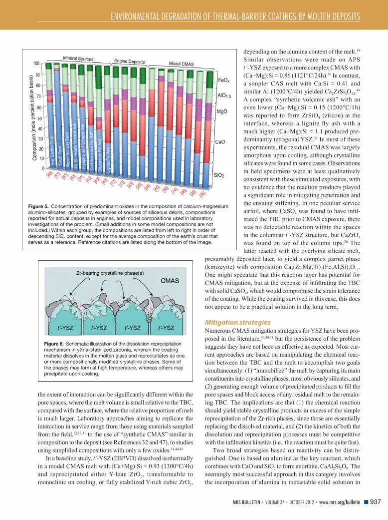
ENVIRONMENTAL DEGRADATION OF THERMAL-BARRIER COATINGS BY MOLTEN DEPOSITS
937MRS BULLETIN • VOLUME 37 • OCTOBER 2012 • www.mrs.org/bulletin
the extent of interaction can be signifi cantly different within the
pore spaces, where the melt volume is small relative to the TBC,
compared with the surface, where the relative proportion of melt
is much larger. Laboratory approaches aiming to replicate the
interaction in service range from those using materials sampled
from the fi eld, 12 , 13 , 31 to the use of “synthetic CMAS” similar in
composition to the deposit (see References 32 and 47 ), to studies
using simplifi ed compositions with only a few oxides. 14 , 44 , 49
In a baseline study, t’- YSZ (EBPVD) dissolved isothermally
in a model CMAS melt with (Ca+Mg):Si ≈ 0.93 (1300°C/4h)
and reprecipitated either Y-lean ZrO 2 , transformable to
monoclinic on cooling, or fully stabilized Y-rich cubic ZrO 2 ,
depending on the alumina content of the melt. 14
Similar observations were made on APS
t’- YSZ exposed to a more complex CMAS with
(Ca+Mg):Si ≈ 0.86 (1121°C/24h). 30 In contrast,
a simpler CAS melt with Ca:Si ≈ 0.41 and
similar Al (1200°C/4h) yielded Ca 2 ZrSi 4 O 12 . 49
A complex “synthetic volcanic ash” with an
even lower (Ca+Mg):Si ≈ 0.15 (1200°C/1h)
was reported to form ZrSiO 4 (zircon) at the
interface, whereas a lignite fl y ash with a
much higher (Ca+Mg):Si ≈ 1.1 produced pre-
dominantly tetragonal YSZ. 31 In most of these
experiments, the residual CMAS was largely
amorphous upon cooling, although crystalline
silicates were found in some cases. Observations
in fi eld specimens were at least qualitatively
consistent with these simulated exposures, with
no evidence that the reaction products played
a signifi cant role in mitigating penetration and
the ensuing stiffening. In one peculiar service
airfoil, where CaSO 4 was found to have infi l-
trated the TBC prior to CMAS exposure, there
was no detectable reaction within the spaces
in the columnar t’- YSZ structure, but CaZrO 3
was found on top of the column tips. 26 The
latter reacted with the overlying silicate melt,
presumably deposited later, to yield a complex garnet phase
(kimzeyite) with composition Ca 3 (Zr,Mg,Ti) 2 (Fe,Al,Si) 3 O 12 .
One might speculate that this reaction layer has potential for
CMAS mitigation, but at the expense of infi ltrating the TBC
with solid CaSO 4 , which would compromise the strain tolerance
of the coating. While the coating survived in this case, this does
not appear to be a practical solution in the long term.
Mitigation strategies Numerous CMAS mitigation strategies for YSZ have been pro-
posed in the literature, 46 , 50 , 51 but the persistence of the problem
suggests they have not been as effective as expected. Most cur-
rent approaches are based on manipulating the chemical reac-
tion between the TBC and the melt to accomplish two goals
simultaneously: (1) “immobilize” the melt by capturing its main
constituents into crystalline phases, most obviously silicates, and
(2) generating enough volume of precipitated products to fi ll the
pore spaces and block access of any residual melt to the remain-
ing TBC. The implications are that (1) the chemical reaction
should yield stable crystalline products in excess of the simple
reprecipitation of the Zr-rich phases, since those are essentially
replacing the dissolved material, and (2) the kinetics of both the
dissolution and reprecipitation processes must be competitive
with the infi ltration kinetics (i.e., the reaction must be quite fast).
Two broad strategies based on reactivity can be distin-
guished. One is based on alumina as the key reactant, which
combines with CaO and SiO 2 to form anorthite, CaAl 2 Si 2 O 8 . The
seemingly most successful approach in this category involves
the incorporation of alumina in metastable solid solution in
Figure 5. Concentration of predominant oxides in the composition of calcium-magnesium
alumino-silicates, grouped by examples of sources of siliceous debris, compositions
reported for actual deposits in engines, and model compositions used in laboratory
investigations of the problem. (Small additions in some model compositions are not
included.) Within each group, the compositions are listed from left to right in order of
descending SiO 2 content, except for the average composition of the earth’s crust that
serves as a reference. Reference citations are listed along the bottom of the image.
Figure 6. Schematic illustration of the dissolution-reprecipitation
mechanism in yttria-stabilized zirconia, wherein the coating
material dissolves in the molten glass and reprecipitates as one
or more compositionally modifi ed crystalline phases. Some of
the phases may form at high temperature, whereas others may
precipitate upon cooling.
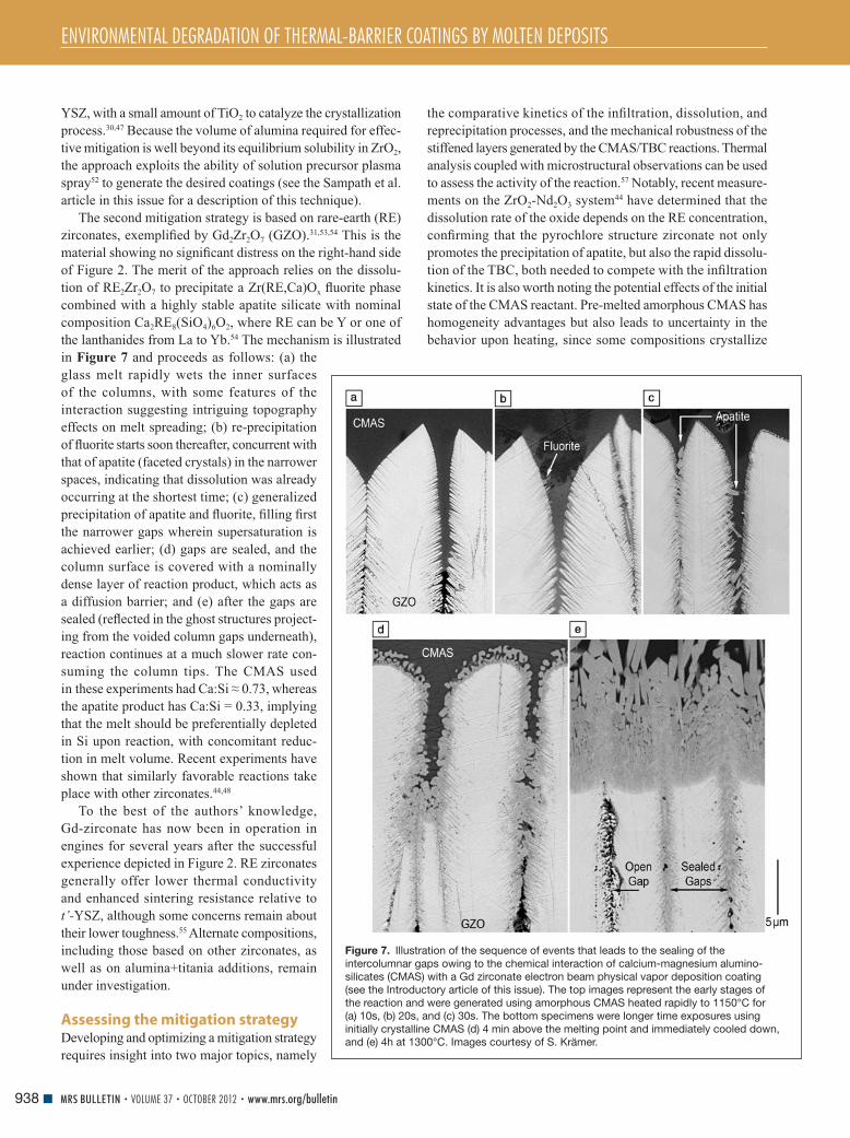
ENVIRONMENTAL DEGRADATION OF THERMAL-BARRIER COATINGS BY MOLTEN DEPOSITS
938 MRS BULLETIN • VOLUME 37 • OCTOBER 2012 • www.mrs.org/bulletin
YSZ, with a small amount of TiO 2 to catalyze the crystallization
process. 30 , 47 Because the volume of alumina required for effec-
tive mitigation is well beyond its equilibrium solubility in ZrO 2 ,
the approach exploits the ability of solution precursor plasma
spray 52 to generate the desired coatings (see the Sampath et al.
article in this issue for a description of this technique).
The second mitigation strategy is based on rare-earth (RE)
zirconates, exemplifi ed by Gd 2 Zr 2 O 7 (GZO). 31 , 53 , 54 This is the
material showing no signifi cant distress on the right-hand side
of Figure 2 . The merit of the approach relies on the dissolu-
tion of RE 2 Zr 2 O 7 to precipitate a Zr(RE,Ca)O x fl uorite phase
combined with a highly stable apatite silicate with nominal
composition Ca 2 RE 8 (SiO 4 ) 6 O 2 , where RE can be Y or one of
the lanthanides from La to Yb. 54 The mechanism is illustrated
in Figure 7 and proceeds as follows: (a) the
glass melt rapidly wets the inner surfaces
of the columns, with some features of the
interaction suggesting intriguing topography
effects on melt spreading; (b) re-precipitation
of fl uorite starts soon thereafter, concurrent with
that of apatite (faceted crystals) in the narrower
spaces, indicating that dissolution was already
occurring at the shortest time; (c) generalized
precipitation of apatite and fl uorite, fi lling fi rst
the narrower gaps wherein supersaturation is
achieved earlier; (d) gaps are sealed, and the
column surface is covered with a nominally
dense layer of reaction product, which acts as
a diffusion barrier; and (e) after the gaps are
sealed (refl ected in the ghost structures project-
ing from the voided column gaps underneath),
reaction continues at a much slower rate con-
suming the column tips. The CMAS used
in these experiments had Ca:Si ≈ 0.73, whereas
the apatite product has Ca:Si = 0.33, implying
that the melt should be preferentially depleted
in Si upon reaction, with concomitant reduc-
tion in melt volume. Recent experiments have
shown that similarly favorable reactions take
place with other zirconates. 44 , 48
To the best of the authors’ knowledge,
Gd-zirconate has now been in operation in
engines for several years after the successful
experience depicted in Figure 2 . RE zirconates
generally offer lower thermal conductivity
and enhanced sintering resistance relative to
t’- YSZ, although some concerns remain about
their lower toughness. 55 Alternate compositions,
including those based on other zirconates, as
well as on alumina+titania additions, remain
under investigation.
Assessing the mitigation strategy Developing and optimizing a mitigation strategy
requires insight into two major topics, namely
the comparative kinetics of the infi ltration, dissolution, and
reprecipitation processes, and the mechanical robustness of the
stiffened layers generated by the CMAS/TBC reactions. Thermal
analysis coupled with microstructural observations can be used
to assess the activity of the reaction. 57 Notably, recent measure-
ments on the ZrO 2 -Nd 2 O 3 system 44 have determined that the
dissolution rate of the oxide depends on the RE concentration,
confi rming that the pyrochlore structure zirconate not only
promotes the precipitation of apatite, but also the rapid dissolu-
tion of the TBC, both needed to compete with the infi ltration
kinetics. It is also worth noting the potential effects of the initial
state of the CMAS reactant. Pre-melted amorphous CMAS has
homogeneity advantages but also leads to uncertainty in the
behavior upon heating, since some compositions crystallize
Figure 7. Illustration of the sequence of events that leads to the sealing of the
intercolumnar gaps owing to the chemical interaction of calcium-magnesium alumino-
silicates (CMAS) with a Gd zirconate electron beam physical vapor deposition coating
(see the Introductory article of this issue). The top images represent the early stages of
the reaction and were generated using amorphous CMAS heated rapidly to 1150°C for
(a) 10s, (b) 20s, and (c) 30s. The bottom specimens were longer time exposures using
initially crystalline CMAS (d) 4 min above the melting point and immediately cooled down,
and (e) 4h at 1300°C. Images courtesy of S. Krämer.

ENVIRONMENTAL DEGRADATION OF THERMAL-BARRIER COATINGS BY MOLTEN DEPOSITS
939MRS BULLETIN • VOLUME 37 • OCTOBER 2012 • www.mrs.org/bulletin
and then melt, whereas others soften gradually, complicating
the interpretation of the heat evolution history. 57
Thermomechanical assessment of CMAS infi ltrated/reacted
systems is still in its infancy. Thermal gradient tests are essential
since “isothermal” furnace cycle tests can lead to mislead-
ing results, and tests at 1300°C and above would compromise
superalloy substrates. Jet engine thermal shock (JETS) tests 50 , 56
are often used to assess the performance of TBCs under thermal
gradients and have been extended to CMAS testing (see the
Va β en et al. article in this issue). Burner rigs have also been
modifi ed to enable the injection of CMAS precursor solutions
through the fl ame 45 and are used successfully for testing plasma
spray ZrYAlTiO x coatings. 58 In both cases, the temperatures in
the front and back of the specimen are measured during the cycle
and used to calculate the evolution of the strain energy. 28
A thermal gradient test based on a laser heat source, schemat-
ically depicted in Figure 8 a, has been recently developed. 59
Proper specimen design allows monitoring of not only the
temperature at the surface and the backside of the substrate,
but also near the TGO/TBC interface. Thermal histories can
be accurately recorded and carefully manipulated using the
laser power-up and -down rates (e.g., Figure 8b ). In addition,
the system is set up with blue LED illumination and suitable
fi lters, 60 allowing visual monitoring of the coating surface during
heating and cooling. The thermal history can then be cast
in terms of Δ T sub and Δ T sur/sub (as discussed in the section on
Understanding the driving force for thermomechanical failure),
and used to calculate the strain energy buildup during cooling,
Figure 8c . Specimens are then examined after testing to identify
the type and extent of damage, Figure 8d–e , which can in turn
be correlated to the thermal history. It is anticipated that this
instrument will be invaluable in testing materials systems and
in helping refi ne the models needed to build life prediction
capabilities for TBCs with CMAS.
Outlook The CMAS problem in thermal-barrier coatings (TBCs) is
intrinsically thermomechanical, but thermochemical issues are
relevant to formulating an effective mitigation strategy. Because
the driving force for delamination scales with the square of
the temperature drop, the problem is expected to increase in
severity as TBCs are pushed to higher surface temperatures,
while the TBC/thermally grown oxide interface remains near
present levels. The grand challenge of the fi eld is the search for
a viable oxide that offers both CMAS resistance and adequate
toughness. For zirconia/hafnia based systems, the challenge
arises from the dichotomy in design approaches viz , CMAS
resistant compositions require large concentrations of reactive
dopants [Y, RE, Al], whereas tough compositions are based on
tetragonal crystal structures with much lower dopant content.
Developing the science base to guide the materials develop-
ment effort requires the effective integration of modeling and
Figure 8. Illustration of a (a) thermal gradient test based on a continuous CO 2 laser with backside cooling and extensive instrumentation
used to probe the response of coatings infi ltrated with calcium-magnesium alumino-silicates to various thermal excursions. The thermal
histories (e.g., (b)) can be varied over a substantial range, and ensuing thermal stresses and associated strain energies can be estimated
based on models such as those described in the text; (c) projection of the surface in Figure 3 where the contours represent different levels
of elastic energy and the paths are two representative thermal excursions corresponding to the samples whose micrographs are illustrated
in (d) and (e). The insets show details of the cracks and in (e) the layer of reaction products on the surface of the GZO. Images courtesy of
R.W. Jackson.

ENVIRONMENTAL DEGRADATION OF THERMAL-BARRIER COATINGS BY MOLTEN DEPOSITS
940 MRS BULLETIN • VOLUME 37 • OCTOBER 2012 • www.mrs.org/bulletin
experimental activities, ideally under an integrated computational
materials engineering (ICME) framework. 61 There is a paucity
of thermodynamic information on the relevant multicompo-
nent systems to help identify promising compositions that may
enable both improvements in toughness and effective reactivity
with CMAS melts, as well as to evaluate the sensitivity of candi-
date materials to the expected variability in melt compositions.
Improvements are also needed in the modeling outlined in this
article for predicting delamination driving forces, including,
for example, assessment of the extent of stress relaxation at the
highest temperatures and during cool-down and the interplay
of multilayer architectures. Studies on the relevant infi ltration,
dissolution, and crystallization kinetics for the appropriate com-
binations of silicate melts and thermal barrier oxides are also
essential. Once desirable compositions are identifi ed, it would
be necessary to develop the processing science to enable their
optimal synthesis into coatings.
On the experimental side, there is a long-standing need for
adequate methods for measuring and characterizing the
mechanical and thermal properties of coatings at high temper-
atures, including microstructures produced by thermochemical
interactions. It is worth noting that it has been a signifi cant chal-
lenge for the fi eld to devise methods to measure delamination
toughness, yet this is crucial in developing design approaches
to TBCs. Only within the past few years have experimental
methods emerged that are capable of measuring coating and
interface toughness with reasonable accuracy, but only at tem-
peratures close to ambient. The challenges are daunting, but so
are the needs for improving materials that would enable more
effi cient gas turbines for energy and propulsion.
Acknowledgments This article draws on lessons from research supported by
the Offi ce of Naval Research (CGL) and the French Defense
Research Organization (MHVS). The authors are indebted to
Dr. M.J. Maloney (PWA) for use of the illustration in Figure 2 ,
as well as to Drs. O. Lavigne (ONERA), D. Konitzer, and
D. Lipkin (GE) and Professors N.P. Padture (Brown) and M.R.
Begley (UCSB) for helpful discussions. The contributions of
Drs. R.W. Jackson and S. Krämer at UCSB are gratefully
acknowledged.
References 1. D.W. McKee , P.A. Siemers , Thin Solid Films 73 , 439 ( 1980 ). 2. A.S. Nagelberg , J. Electrochem. Soc. 132 ( 10 ), 2502 ( 1985 ). 3. R.L. Jones , C.E. Williams , Surf. Coat. Technol. 349 ( 1987 ). 4. C. Leyens , I.G. Wright , B.A. Pint , Oxid. Met. 54 ( 5/6 ), 401 ( 2000 ). 5. T.E. Strangman , Thin Solid Films 127 , 93 ( 1985 ). 6. T.E. Strangman , J. Neumann , A. Liu , “Thermal Barrier Coating Life—Prediction Model Development; Final Report” (NASA–Lewis Research Center , 1987 ). 7. R.L. Jones , “Experiences in Seeking Stabilizers for Zirconia having Hot Corrosion-Resistance and High Temperature Tetragonal (t’) Stability” (NRL/MR/6170–96–7841, Naval Research Laboratory , 1996 ). 8. S. Raghavan , M.J. Mayo , Surf. Coat. Technol. 160 , 187 ( 2002 ). 9. F.M. Pitek , C.G. Levi , Surf. Coat. Technol. 201 , 6044 ( 2007 ). 10. M.A. Alvin , F.S. Pettit , G.H. Meier , N.M. Yanar , M. Chyu , D. Mazzotta , W. Slaughter , V. Karaivanov , B. Kang , C. Feng , R. Chen , T.C. Fu , in 5th International Conference on Advances in Materials Technology for Fossil Power Plants , R. Viswanathan , D. Gandy , K. Coleman , Eds. ( Electric Power Research Institute, Inc. , Marco Island, FL , 2008 ), pp. 413 – 423 .
11. J.L. Smialek , F.A. Archer , R.G. Garlick , JOM 46 ( 12 ), 39 ( 1994 ). 12. F.H. Stott , D.J. de Wet , R. Taylor , MRS Bull. 19 ( 10 ), 46 ( 1994 ). 13. M.P. Borom , C.A. Johnson , L.A. Peluso , Surf. Coat. Technol. 86 – 87 , 116 ( 1996 ). 14. S. Krämer , J.Y. Yang , C.A. Johnson , C.G. Levi , J. Am. Ceram. Soc. 89 ( 10 ), 3167 ( 2006 ). 15. K.M. Grant , S. Krämer , J.P.A. Löfvader , C.G. Levi , Surf. Coat. Technol. 202 , 653 ( 2007 ). 16. K.M. Grant , S. Krämer , G.G.E. Seward , C.G. Levi , J. Am. Ceram. Soc. 93 ( 10 ), 3504 ( 2010 ). 17. J.L. Smialek , “The Chemistry of Saudi Arabian Sand: A Deposition Problem on Helicopter Turbine Airfoils” (NASA TM-105234, NASA Lewis Research Center , 1991 ). 18. W. Braue , J. Mater. Sci. 44 , 1664 ( 2009 ). 19. A.G. Evans , D.R. Clarke , C.G. Levi , J. Eur. Ceram. Soc. 28 ( 7 ), 1405 ( 2008 ). 20. C. Mercer , S. Faulhaber , A.G. Evans , R. Darolia , Acta Mater. 53 ( 4 ), 1029 ( 2005 ). 21. S. Krämer , S. Faulhaber , M. Chambers , D.R. Clarke , C.G. Levi , J.W. Hutchinson , A.G. Evans , Mater. Sci. Eng., A 490 , 26 ( 2008 ). 22. V.K. Tolpygo , private communication . 23. K.M. Wessels , R.W. Jackson , D.G. Konitzer , T.M. Pollock , C.G. Levi , presented at the International Conference on Metallurgical Coatings and Thin Films, San Diego, CA , 2012 . 24. L. Li , D.R. Clarke , Int. J. Appl. Ceram. Technol. 5 ( 3 ), 278 ( 2008 ). 25. J. Wu , H.B. Guo , Y.Z. Gao , S.K. Gong , J. Eur. Ceram. Soc. 31 , 1881 ( 2011 ). 26. W. Braue , P. Mechnich , J. Am. Ceram. Soc. 94 ( 12 ), 4483 ( 2011 ). 27. M.J. Maloney , in Turbine Forum ( Forum of Technology , Germany, Nice-Port St. Laurent, France , 2006 ). 28. A.G. Evans , J.W. Hutchinson , Surf. Coat. Technol. 201 , 7905 ( 2007 ). 29. S. Sundaram , D.M. Lipkin , C.A. Johnson , J.W. Hutchinson , J. Appl. Mech. ( 2012 ), in press . 30. A. Aygun , A.L. Vasiliev , N.P. Padture , X. Ma , Acta Mater. 55 ( 20 ), 6734 ( 2007 ). 31. A.D. Gledhill , K.M. Reddy , J.M. Drexler , K. Shinoda , S. Sampath , N.P. Padture , Mater. Sci. Eng., A 528 , 7214 ( 2011 ). 32. P. Mechnich , W. Braue , U. Schulz , J. Am. Ceram. Soc. 94 ( 3 ), 925 ( 2011 ). 33. M.-P. Bacos , J.-M. Dorvaux , O. Lavigne , R. Mévrel , M. Poulain , C. Rio , M.-H. Vidal-Setif , in Aerospace Lab: The ONERA Journal ( ONERA , Chatillon, France , 2011 ), issue 3 . 34. R.A. Miller , J.L. Smialek , R.G. Garlick , in Science and Technology of Zirconia , A.H. Heuer , L.W. Hobbs , Eds. ( The American Ceramic Society , Columbus, OH , 1981 ), vol. 3 , pp. 241 – 253 . 35. J.A. Krogstad , S. Krämer , D.M. Lipkin , C.A. Johnson , D.R.G. Mitchell , J.M. Cairney , C.G. Levi , J. Am. Ceram. Soc. 94 ( S1 ), S168 ( 2011 ). 36. D.M. Lipkin , J.A. Krogstad , Y. Gao , C.A. Johnson , W.A. Nelson , C.G. Levi , J. Am. Ceram. Soc. ( 2012 ), in press. 37. M.J. Maloney , US Patent 6,177,200 , 2001 . 38. R. Vassen , A. Stuke , D. Stöver , J. Therm. Spray Technol. 18 ( 2 ), 181 ( 2009 ). 39. T.E. Strangman , D. Raybould , A. Jameel , W. Baker , Surf. Coat. Technol. 202 , 658 ( 2007 ). 40. W.E. Ford , in Dana’s Textbook of Mineralogy with an Extended Treatise on Crystallography and Physical Mineralogy, 4th Edition ( Wiley , New York , 1954 ). 41. PTI , “Material Safety Data Sheet: Airport Runway Sand” ( 2007 ); www . powdertechnologyinc . com / secondary / msds . php . 42. H.E. Taylor , F.E. Lichte , Geophys. Res. Lett. 7 ( 11 ), 949 ( 1980 ). 43. W. Chesner , R. Collins , M. MacKay , J. Emery , “User Guidelines for Waste and Byproduct Materials in Pavement Construction” (Federal Highway Administration, Washington, DC, 1997) . 44. N. Chellah , M.-H. Vidal-Sétif , C. Petitjean , P.-J. Panteix , C. Rapin , M. Vilasi , in 8th International Symposium on High Temperature Corrosion and Protection of Materials (HTCPM8) ( Les Embiez , France , 2012 ). 45. T. Steinke , D. Sebold , D.E. Mack , R. Vaßen , D. Stöver , Surf. Coat. Technol. 205 , 2287 ( 2010 ). 46. A.K. Rai , R.S. Bhattacharya , D.E. Wolfe , T.J. Eden , Int. J. Appl. Ceram. Technol. 7 ( 5 ), 662 ( 2010 ). 47. J.M. Drexler , K. Shinoda , A.L. Ortiz , D. Li , A.L. Vasiliev , A.D. Gledhill , S. Sampath , N.P. Padture , Acta Mater. 58 6835 ( 2010 ). 48. J.M. Drexler , A.L. Ortiz , N.P. Padture , Acta Mater. 60 5437 ( 2012 ). 49. M.-P. Bacos , J.-M. Dorvaux , S. Landais , O. Lavigne , R. Mévrel , M. Poulain , C. Rio , M.-H. Vidal-Sétif , in Aerospace Lab: The ONERA Journal ( ONERA , Chatillon, France , 2011 ), issue 3 . 50. W.C. Hasz , C.A. Johnson , M.P. Borom , US Patent 5,660,885 ( 1997 ).
ENVIRONMENTAL DEGRADATION OF THERMAL-BARRIER COATINGS BY MOLTEN DEPOSITS
941MRS BULLETIN • VOLUME 37 • OCTOBER 2012 • www.mrs.org/bulletin
51. M. Fu , R. Darolia , M.D. Gorman , B.A. Nagaraj , US Patent 8,062,759 ( 2007 ). 52. N.P. Padture , K.W. Schlichting , T. Bhatia , A. Ozturk , B. Cetegen , E.H. Jordan , M. Gell , S. Jiang , T.D. Xiao , P.R. Strutt , E. Garcia , P. Miranzo , M.I. Osendi , Acta Mater. 49 , 2251 ( 2001 ). 53. S. Krämer , J.Y. Yang , C.G. Levi , J. Am. Ceram. Soc. 91 ( 2 ), 576 ( 2008 ). 54. J.M. Drexler , C.H. Chen , A.D. Gledhill , K. Shinoda , S. Sampath , N.P. Padture , Surf. Coat. Technol. 206 , 3911 ( 2012 ). 55. R.G. Wellman , J.R. Nicholls , Tribol. Int. 41 , 657 ( 2008 ). 56. R.V. Hillery , B.H. Pilsner , R.L. McKnight , T.S. Cook , M.S. Hartle , “Thermal Barrier Coating Life Prediction Model Development” (NASA CR 180807, General Electric, 1988) .
57. E. Zaleski , R.W. Jackson , C. Ensslen , C.G. Levi , 8th International Symposium on High Temperature Corrosion and Protection of Materials (HTCPM8) ( Les Embiez , France , 2012 ). 58. J.M. Drexler , A. Aygun , D. Li , R. Vaßen , T. Steinke , N.P. Padture , Surf. Coat. Technol. 204 ( 16–17 ), 2683 ( 2010 ). 59. R.W. Jackson , E.M. Zaleski , M.R. Begley , C.G. Levi , in International Conference on Metallurgical Coatings and Thin Films ( San Diego, CA , 2012 ). 60. M.D. Novak , F.W. Zok , Rev. Sci. Instrum. 82 ( 115101 ) ( 2012 ). 61. NRC , “Integrated Computational Materials Engineering: A Transformational Discipline for Improved Competitiveness and National Security” (9780309119993, The National Academies Press, Washington, DC, 2008) .
Breaking Research News
MRS News
Hot Topics
Featured Journal Articles
Videos and Podcasts
Education and Outreach Links
Twitter Feeds
And More Your
Sea
rch
Stop
s He
re!
INTRODUCING MATERIALS360 ONLINEThe Materials Research Society (MRS) and Cambridge University Press
proudly announce the launch of a new website dedicated to materials
science news, Materials360 Online.
Materials360 Online features original news stories, videos and podcasts
reported and written by MRS staff, volunteers and freelancers. The site
also brings you news stories aggregated from many other major scientific
publications and websites, so you won’t have to search anywhere else for
your materials news. The search stops here! Visit regularly and don’t miss
a single day’s worth of valuable news and information.
www.materials360online.com