thermal and dynamic analysis of bearing assembly for...
TRANSCRIPT
INSTITUTE OF TECHNOLOGY, NIRMA UNIVERSITY, AHMEDABAD – 382 481, 8-10 DECEMBER, 2011
1
Abstract--General solution procedure is given to enhance the
loading capacity of 10 MW Siemens200 steam turbine(SST200)
by adopting the 110/180 mm size bearing in 90/160 mm size
bearing casing. First 90/160 mm bearing with casing is modeled
in Pro-E wildfire 4.0 and analyzed in ANSYS workbench 12.0
for mechanical and thermal loads and benchmarked. Then
modification is done in 90/160 mm bearing casing to
accommodate 110/180 mm bearing. At last modified bearing
casing is analyzed with 110/180 mm bearing and found suitable
for use.
Index terms—Mechanical load, Thermal load, Turbine
Bearing
I. INTRODUCTION
ilting pad type thrust bearings are used in a wide variety
of rotating machinery where significant thrust loads must
be accommodated [1]. Thrust load is transmitted from
rotor to stator through hydrodynamic oil films that generate
between a rotating collar on shaft and pads in bearing [2]. The
lubricant used was ISO VG 46 turbine oil [3]. Also modal
analysis is carried out and heat load is found out.
II. STATIC ANALYSIS
First of all the part drawings of tilting pad, thrust pad,
radial bearing, axial bearing, bearing casing are provided. The
3-D solid models are prepared using Pro-E Wildfire 4.0 [4] of
various parts. The forces are identified and the static analysis
is carried out using Ansys Workbench 12.0.
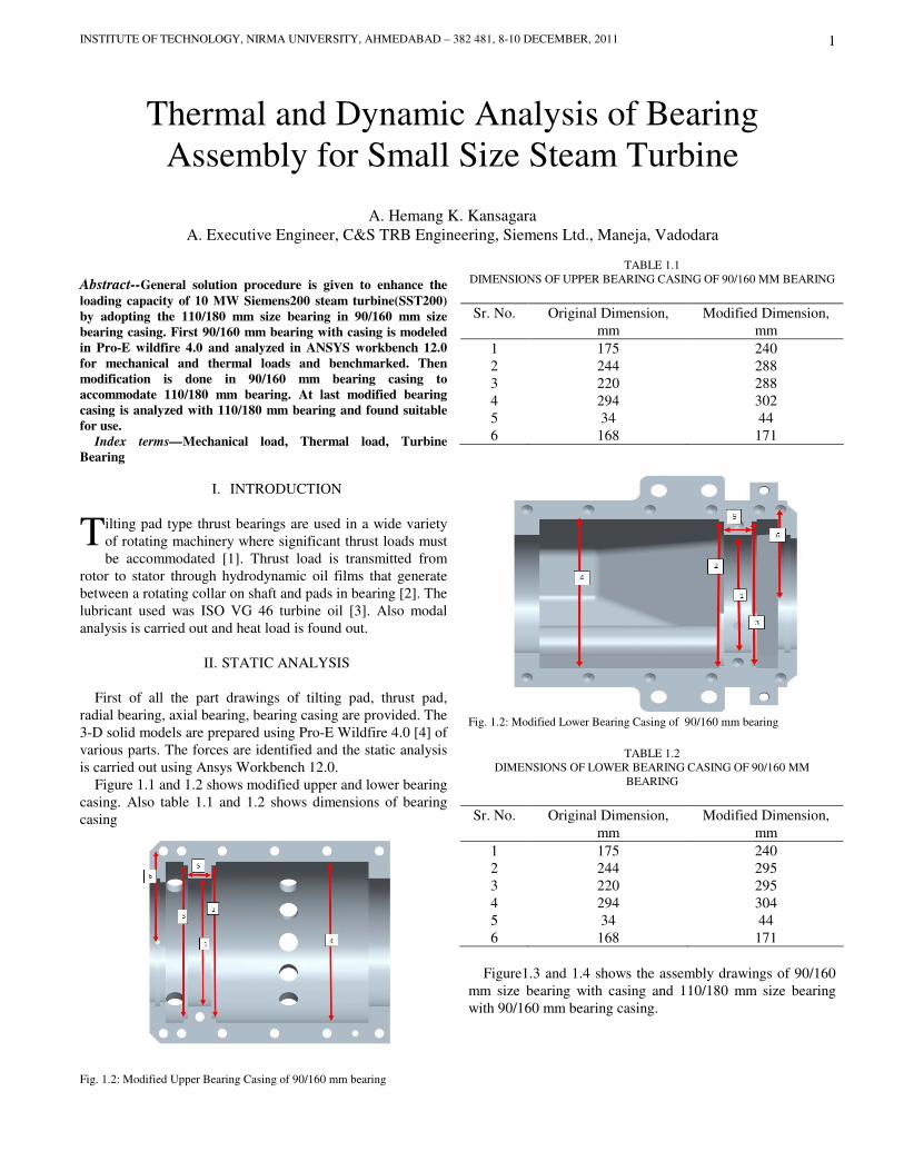
Figure 1.1 and 1.2 shows modified upper and lower bearing
casing. Also table 1.1 and 1.2 shows dimensions of bearing
casing
Fig. 1.2: Modified Upper Bearing Casing of 90/160 mm bearing
TABLE 1.1
DIMENSIONS OF UPPER BEARING CASING OF 90/160 MM BEARING
Sr. No. Original Dimension,
mm
Modified Dimension,
mm
1 175 240
2 244 288
3 220 288
4 294 302
5 34 44
6 168 171
Fig. 1.2: Modified Lower Bearing Casing of 90/160 mm bearing
TABLE 1.2
DIMENSIONS OF LOWER BEARING CASING OF 90/160 MM
BEARING
Sr. No. Original Dimension,
mm
Modified Dimension,
mm
1 175 240
2 244 295
3 220 295
4 294 304
5 34 44
6 168 171
Figure1.3 and 1.4 shows the assembly drawings of 90/160
mm size bearing with casing and 110/180 mm size bearing
with 90/160 mm bearing casing.
Thermal and Dynamic Analysis of Bearing
Assembly for Small Size Steam Turbine
A. Hemang K. Kansagara
A. Executive Engineer, C&S TRB Engineering, Siemens Ltd., Maneja, Vadodara
T

INTERNATIONAL CONFERENCE ON CURRENT TRENDS IN TECHNOLOGY, ‘NUiCONE – 2011’
2
Fig. 1.3: Assembly drawing of small size bearing with casing
Fig. 1.4: Assembly drawing of big size bearing with small casing
The stresses generated on axial pad and bearing casing due to
axial and radial force.
Radial Load = 9751 N
Thrust Load = 39687 N
Fig. 1.3: Static Analysis of 90/160 mm bearing with casing
Fig. 1.4: Static Analysis of 110/180 mm bearing with 90/160 mm bearing
casing
The von-Mises stress for 90/160 mm bearing is 51.056
MPa and for 110/180 mm bearing is 45.478 MPa. The stress
values are coming nearer to same. So, 110/180 mm bearing
is suitable in 90/160 mm bearing casing.
III. THERMAL ANALYSIS
Heat load calculation, oil outlet temperature and static
analysis with temperature effect are carried out. First 90/160
mm bearing with casing is analyzed for benchmarked and
then analyzed for 110/180 mm bearing with 90/160 mm
bearing casing.
1) Heat Load by Free Convection
Heat generated at radial and axial of 90/160 mm size
bearing is partly carried away by lubricating oil circulated in
the bearing and partly by natural convection to atmosphere.
Surface temperature of
bearing casing Ts
67°C
Free stream temperature T1 33°C
Diameter of bearing [380-(240+225)/2] = 147.5mm
Characteristic length of
bearing
450 mm
Properties of air at mean
temperature Tm [5]
(67+33)/2 =50°C

INSTITUTE OF TECHNOLOGY, NIRMA UNIVERSITY, AHMEDABAD – 382 481, 8-10 DECEMBER, 2011
3
So,
Rayleigh No is given by,
Nusselt No is given by, [6]
Therefore convective heat transfer coefficient is given by,
Heat loss is given by,
2) Heat Carried away by Oil
The lubricating oil enters in the bearing, it absorbs heat.
This high temperature oil is recirculated through oil cooler
where it is cooled to predefine temperature. This cooled oil is
again recirculate in the bearing.
Volume flow rate of oil 122 lit/min
Specific heat of oil 1976.1696 J/kg°C
Density of oil 861 kg/m3
Inlet temperature of oil 49°C
Outlet temperature of oil 68°C
Hence heat carried away by oil,
3) Heat load by Force Convection
Heat is transferred by force convection at axial and radial
bearing. [7]
Surface temperature of rotor 80°C
Free stream temperature of
air
49°C
Properties of oil at mean
temperature Tm
(80+49)/2=64.5°C
Prandtl No is given by, [8]
For Radial Bearing,
Reynold No,
Nusselt No, [9]
Hence, Convective heat transfer coefficient
Same procedure is done three times so,
Heat loss is given by,
Similarly procedure is carried out for axial bearing. Hence
heat loss is given by,
Total heat loss,
4) Heat Generation by Friction
When rotor rotates in bearing at that time due to friction heat
is generated.
Axial Force = 47712.5 N
Radial Force = 9751.6 N
Radius = 0.045 m
Speed = 12000 rpm
Coefficient of friction = 0.0176
Heat load by radial bearing,
Same for axial bearing,
Hence total heat load is generated due to frictional effect,
Balancing heat loss,
5) Oil Outlet Temperature of 90/160 mm bearing
3
2
( )7.4090 8s
a r
g T T DR P e
β
ν∞∗ ∗ − ∗
= ∗ =
1/ 62
9/16 8/ 27
0.387*[0.6 ] 105.6332
0.559[1 ( ) ]
au
r
RN
P
= + =
+
26.4202
conv
wh
m k=
( ) 148.2386s
Q hA T T w∞= − =
65733.9223p
Q mC T w= ∆ =
p
r
CP
k
µ= 227.3546=
11
he
vDR
ρ
µ= 6.32014 5e=
1/ 2 2 /3
( )* *2 11553.0332
1.07 12.7*( ) *[ 1]2
e r
u
r
fR P
Nf
P
= =
+ −
1 21993.7613
Wh
m K⇒ =
*e
u
h DN
K=
2 22336.7974
Wh
m K= 3 2
1993.7613W
hm K
=
4 23268.7550
Wh
m K=
1 1 2 2 3 3[ ]* 2541.5120radial
Q hA h A h A h A T w= + + + ∆ =
2992.2787axial
Q W=
5533.7907total axial radial
Q Q Q w= + =
* 9772.7423radial
Q T wω= =
47486.1797axial
Q w=
57258.922total radial axial
Q Q Q w= + =
frictional force oil freeQ Q Q Q+ = +
62792.7127 65882.1609w w∴ ≅
pQ mC T= ∆
102.5 344000 *861*1976.1696*( 49)
60o
eT
−∴ = −
64.14o
T C⇒ = o
INTERNATIONAL CONFERENCE ON CURRENT TRENDS IN TECHNOLOGY, ‘NUiCONE – 2011’
4
Heat Load from Turbine Casing body to bearing body by
conduction,
Hence, outlet temperature is given by,
5.1) Thermal Analysis of 90/160 mm bearing
Material for Radial bearing: 42CrMoS4V
Density 7.80 gm/cm3
Young modulus of Elasticity 2.1e5N/mm2
Coefficient of thermal
expansion
11.7e-6 K-1
Yield strength 500MPa
Thermal conductivity 36W/mK
For axial bearing: 16MnCr5
Density 7.85 gm/cm3
Young modulus of Elasticity 2.1e5N/mm2
Coefficient of thermal
expansion
11.7e-6 K-1
Yield strength 500MPa
Thermal conductivity 41W/mK
For casing: Cast Iron
Density 7.20 gm/cm3
Young modulus of Elasticity 240N/mm2
Coefficient of thermal
expansion
1.1e-5 K-1
Yield strength 250MPa
Thermal conductivity 52W/mK
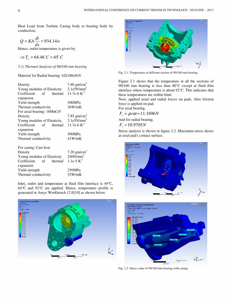
Inlet, outlet and temperature at fluid film interface is 49°C,
64°C and 92°C are applied. Hence, temperature profile is
generated in Ansys Workbench 12.0[10] as shown below.
Fig. 2.1: Temperature at different section of 90/160 mm bearing
Figure 2.1 shows that the temperature at all the sections of
90/160 mm bearing is less than 80°C except at fluid film
interface where temperature is about 92°C. This indicates that
these temperatures are within limit.
Now, applied axial and radial forces on pads. Also friction
force is applied on pad.
For axial bearing,
11.1696r
F r Nµ ω= =
And for radial bearing,
10.9705r
F N=
Stress analysis is shown in figure 2.2. Maximum stress shows
at axial pad's contact surface.
Fig. 2.2: Stress value of 90/160 mm bearing with casing
934.14dt
Q KA wdx
= =
64.46 65o
T C C⇒ = =o o
INSTITUTE OF TECHNOLOGY, NIRMA UNIVERSITY, AHMEDABAD – 382 481, 8-10 DECEMBER, 2011
5
6) Oil Outlet Temperature of 110/180 mm bearing
In this section same procedure is carried out which is done
in section – 5.
Also, heat Load from Turbine Casing body to bearing body
by conduction is 934.14 w. Hence, outlet oil temperature is,
6.1) Thermal Analysis of 110/180 mm bearing with 90/160
mm bearing casing
Same procedure is carried out as per section 5.1. Hence,
temperature profile shows in below figure.
Fig. 2.3: Temperature at different section of 110/180 mm bearing with
90/160 mm bearing casing
Also, Stress analysis is shown in figure 2.4. Maximum
stress shows at axial pad's contact surface.
Fig. 2.4: Stress value of 110/180 mm bearing with 90/160 mm bearing
casing
After doing all analysis results are shown below. Maximum
stress generated at axial pad's contact surface in both case.
TABLE 3.1
THERMAL ANALYSIS RESULT
90/160 mm
bearing with
casing
110/180 mm
bearing with
90/160 mm
bearing casing
Temperature 65°C 69°C
von-Mises Stress
at Thermal
80.467MPa 46.898MPa
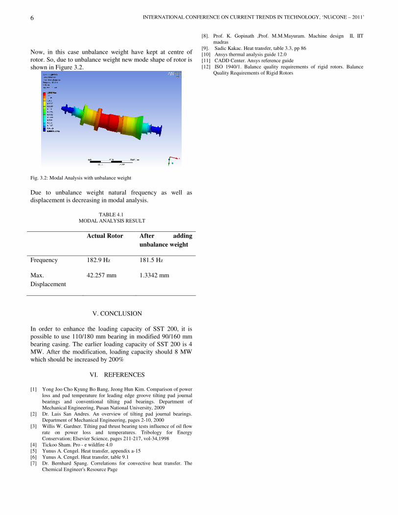
IV. DYNAMIC ANALYSIS
Basically mode shapes and frequency is finding out in
modal analysis. From that we can decide the nature of rotor
during working condition. [11] During working condition,
some unbalance weight will generate and it will act at any
distance which can be found as per ISO 1940/1. [12]
Figure 3.1: Modal analysis without unbalance weight
Unbalance weight is given by,
pQ mC T= ∆
68.08o
T C⇒ = o
68.35 69o
T C C⇒ = ≅o o
12.79per
UW gm
r= =
INTERNATIONAL CONFERENCE ON CURRENT TRENDS IN TECHNOLOGY, ‘NUiCONE – 2011’
6
Now, in this case unbalance weight have kept at centre of
rotor. So, due to unbalance weight new mode shape of rotor is
shown in Figure 3.2.
Fig. 3.2: Modal Analysis with unbalance weight
Due to unbalance weight natural frequency as well as
displacement is decreasing in modal analysis.
TABLE 4.1
MODAL ANALYSIS RESULT
Actual Rotor After adding
unbalance weight
Frequency 182.9 Hz 181.5 Hz
Max.
Displacement
42.257 mm 1.3342 mm
V. CONCLUSION
In order to enhance the loading capacity of SST 200, it is
possible to use 110/180 mm bearing in modified 90/160 mm
bearing casing. The earlier loading capacity of SST 200 is 4
MW. After the modification, loading capacity should 8 MW
which should be increased by 200%
VI. REFERENCES
[1] Yong Joo Cho Kyung Bo Bang, Jeong Hun Kim. Comparison of power
loss and pad temperature for leading edge groove tilting pad journal
bearings and conventional tilting pad bearings. Department of
Mechanical Engineering, Pusan National University, 2009
[2] Dr. Luis San Andres. An overview of tilting pad journal bearings.
Department of Mechanical Engineering, pages 2-10, 2000
[3] Willis W. Gardner. Tilting pad thrust bearing tests influence of oil flow
rate on power loss and temperatures. Tribology for Energy
Conservation; Elsevier Science, pages 211-217, vol-34,1998
[4] Tickoo Sham. Pro - e wildfire 4.0
[5] Yunus A. Cengel. Heat transfer, appendix a-15
[6] Yunus A. Cengel. Heat transfer, table 9.1
[7] Dr. Bernhard Spang. Correlations for convective heat transfer. The
Chemical Engineer's Resource Page
[8]. Prof. K. Gopinath ,Prof. M.M.Mayuram. Machine design II, IIT
madras
[9]. Sadic Kakac. Heat transfer, table 3.3, pp 86
[10] Ansys thermal analysis guide 12.0
[11] CADD Center. Ansys reference guide
[12] ISO 1940/1. Balance quality requirements of rigid rotors. Balance
Quality Requirements of Rigid Rotors