there is only one original the lebus...
TRANSCRIPT

Installation InstructionsL
EB
US
-GR
OO
VE
THERE IS ONLY ONE ORIGINALTHE LEBUS GROOVE

KAWASAKI STAFFA HYDRANOR
HUNGER Linde LEBUS® FAIRFIELD
SCANTROL
LEBUS®
Powertech (China) Ltd., is a leading system and engineering company providing "STATE OF THE
ART" solutions and comprehensive after-sales services in hydraulic drives and controls for customers
in the marine and shipbuilding industry. Our solutions are delivered with distinguished, high quality
and most reliable makes such as KAWASAKI pumps, STAFFA motors. HYDRANOR proportional
winch control blocks, Linde close-loop piston units, LEBUS® grooved drums sleeves, HUNGER cylin-
ders, FAIRFIELD gears, and SCANTROL electronic controls.
Powertech is the sales and technical support partner of LEBUS® International Engineers GmbH in
China.

Installation of wire rope on original LEBUS® parallel grooving 2
Technical information LEBUS® grooving-grooving direction 6
Instructions for installations of LEBUS® grooved sleeves "weld on method" 7
Instructions for installations of LEBUS® grooved sleeves "bolt on method" 10
contents
LEBUS® 13
LEBUS® 17
LEBUS® “ ” 18
LEBUS® “ ” 21

INSTALLATION OF WIRE ROPEON ORIGINAL LEBUS® PARALLEL GROOVING
General Information
In order to fully achieve the service life potential of a wire rope for demanding lifting jobs, some step-by-step most important instructions should be followed. They are intended to prevent rope damage caused by kinks, untwisting, and loose strands, during handling and installation as well as later operation of the equipment.
Original LEBUS® grooving has been designed to give the best wire rope service for rope manufactured to maximum standard Federal Specifications for rope size and tolerance. It is understood and self explanatory that multilayer spool-ing does require intensive care and caution to avoid crushing of the bottom layers when applying high loads on the top layers.
1. Measuring the rope
Before you start anything, make sure the diameter of the new rope you are about to install is the correct one and in accordance with the Lebus recommendation regarding the tolerances. It is the customer‘s or rope manufacturer‘s responsibility to provide a rope construction suitable for the specific application, for multilayer spooling, also suitable for the technical load data given in specification.
Keep a record of the new rope diameter for future references. You will be asked to determine how much the rope diameter has decreased in service and you must know the actual diameter of the rope after the run in period. When measuring the rope, don’t measure the layer on the reel. Pull a couple of metres off the reel and measure the rope when straight. It is advisable to take 4 measurements of the rope round its axis and average the results.
2. Winding the rope on the drum
2.1 About the Original LEBUS® Spooling System
Knowledge of how the LEBUS® Spooling System works is helpful in order to determine if the cable has spooled properly.
2
Reversing Endfiller
Rope Entry
Rise
r
X
Para
llel
Sect
ion
‘A’
Para
llel
Sect
ion
‘B’
X
Para
llel
Sect
ion
‘A’
Star
ting
End
fille
r
Cro
ssov
erSe
ctio
ns
Drum Flanges
FlG,1
FlG,2
Starting Endfiller
Section X-X

INSTALLATION OF WIRE ROPEON ORIGINAL LEBUS® PARALLEL GROOVING
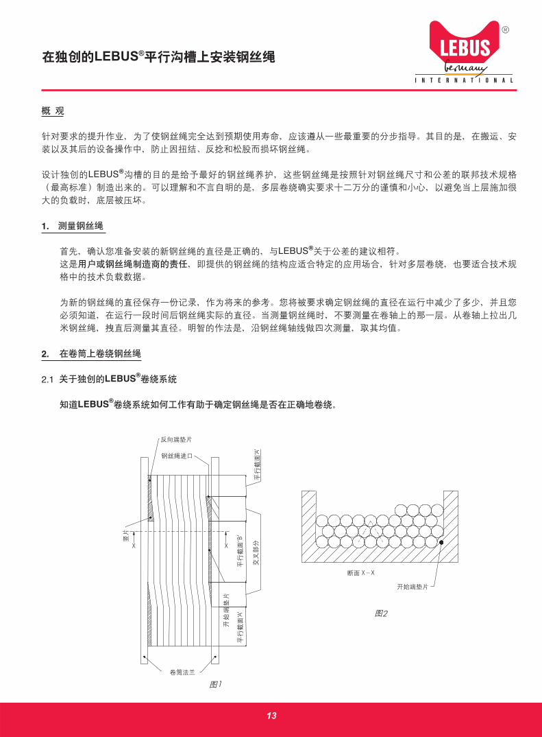
It will be seen from the development of the grooved drum (Figure 1) that the groove is continuous and parallel to the flanges except for the two crossover sections where the groove moves across the drum one-half pitch to give one full pitch of movement per revolution. Use of end fillers and risers of proper design to retain the pyramid pattern illustrated maintain control of the spooling at the flanges.
Original LEBUS® Grooving has been designed to give the best wire rope service for rope manufactured and calcu-lated to withstand high load pressures avoiding deformations when multilayered spooled.
Note: Strictly follow the recommended wire rope Tolerances stated in our specification and drawings for each drum. The idea behind this strict rule is to guarantee a proper pyramidal build-up.
Once the cable has been strung up and anchored in the rope clamps situated on the flange, it is then ready to be spooled. Although spooling should be completely automatic due to the fixed pattern, it is of greatest importance to strictly fulfil the following procedures.
2.2 Tension required for Spooling
When spooling dead wraps (turns) onto the drum, it is very important that they be spooled tight on the drum, every single wrap! Take a mallet or a piece of wood and tap the wraps tightly into the bottom of the grooves. If the dead turns are wound too loose, the next layer will wedge a gap into the dead turns.
The cable should be spooled onto the drum with a minimum tension of a) 10% of the working load or b) 2% of the breaking strength of the wire rope where safety factor breaking load to working load 5 to 1 is involved. The higher value (a or b) must always be used.
The tension should be about 1/3rd of the maximum load where safety factors are 3 to 1 or less.
Above values are understood as average values and will depend on rope construction. Contact your rope manu-facturer for more information.
2.3 Spooling 1st layer and subsequent layers
Many methods may be used to obtain the required tension for spooling a wire rope on a drum. The best system is one that will give the required tension and with the capability of spooling the line back onto the reel or drum should it become necessary, like for example adjusting the LEBUS® spooling device (LEBUS® levelwinder or LEBUS® fleet angle compensator). The use of another hoist is often advisable or a storage reel with a capstan to obtain the proper tension.
The method used to do this work often depends upon availability of equipment on hand. Therefore this operation should be planned in advance.
Hand Spooling the wire rope onto the drum is absolutely unsatisfactory due to lack of required tension unless a short length of wire rope is involved which can be respooled once the cable is on the drum.
3
INSTALLATION OF WIRE ROPEON ORIGINAL LEBUS® PARALLEL GROOVING
In any case, the first layer, as well as all the subsequent layers, must be wound on the drum with sufficient preten-sion. If wound with no tension at all the rope is subjected to premature crushing and flattening caused by the ‘under load’ top layers.
Make sure the cable spools into each groove while winding. This is important because the cable must repeat the groove pattern for the rope to spool up on in the second and subsequent layers.
Check the cable for proper tension as previously mentioned.
Make sure the cable goes down into the last groove properly.
As the cable rises from one layer to the next, watch to see that the cable crosses one-half wrap after one half revo-lution of the drum.
Make sure there are no void wraps of cable when the load has been lowered and the rope has become completely slack.
Remember: A cross section of the cable in each parallel section should look like the section shown in figure 2.
Even if wound on properly during installation, the first layer will loosen somewhat during service. When the first layer becomes slack (the pretension is gone) this initial procedure MUST be repeated in regular intervals. Other-wise the tensioned hard wraps will severely crush the bottom layers.
3. Using Your Rope for the first time
3.1 Break in period
After installing a new rope it is necessary to run it through its operating cycle several times under light load and reduced speeds. This allows the rope to adjust itself to the working conditions and enables all strands and wires to become seated. Depending on the rope type and construction some rope stretch and a slight reduction in rope diameter will occur as the strands and core are compacted. The rope is less liable to be damaged when full load is applied.
3.2 Equipment testing
In many cases the equipment has to be tested prior to use. During the test, the equipment gets purposely over-loaded to varying degrees. The magnitude of overloading depends on the type and capacity of the lifting equipment.
Under NO circumstances must the equipment be tested prior to the break in procedure of the wire rope. If you overload a rope that has not yet been broken in, you may inflict permanent damage to the rope. Multilayer spool-ing calls for most caution. As mentioned before, severe overloads of the top layers may damage the lower ones and/or may crush the rope.
Note: If possible test the winch with the rope spooled in the first drum layer only.
4

INSTALLATION OF WIRE ROPEON ORIGINAL LEBUS® PARALLEL GROOVING
4. Misspooling check list
If misspooling should occur, check for the following items:
Slack line may have worked its way down into the dead turn causing the rope to miss a wrap by one cable being high or misplaced, thus the spooling pattern has been lost.
Misspooling sometimes occurs when a new cable has been installed due to the cable being slightly larger in diam-eter than the groove pitch, which is evident when the wire rope does not stay in the grooves in the first layer.
Misspooling will also occur due to reduction in diameter of the cable due to wear. This is evident when the rope begins to lie low in the wraps adjacent to the drum flange and/or cutting in of the rope may also occur.
The hook or hook- and load may have been set down, causing the rope to become completely slack. This usually causes a void wrap misspool. In either case, spool the cable off the drum to a point past the bad spooling or loosen cable and respool under tension.
If the cable misspools at the drum flange by pulling away from the flange after rising to the next layer and thereby leaving a void wrap, check the LEBUS® spooling device, or if not a LEBUS®spooling device installed, check the first fixed sheave it may be out of alignment.
If misspooling occurs at the drum flange by the line piling upon itself would be due also to misalignment of the first sheave, or in case if a LEBUS® fleet angle compensator is used, the adjustment collar could have slipped off.
5

TECHNICAL INFORMATION LEBUS® GROOVING-GROOVING DIRECTION
LEFTHAND OR RIGHTHAND?One distinguishes between a rope beeing left-hand lay and/or a right hand-lay rope and the direction of the grooving on a drum beeing right-hand or left-hand grooving.
1. Directions of rope lay. (DIN 3051) The term "lay" describes the way the strands rotate in a rope In right hand lay, the strands in a rope rotate clockwise. In left hand lay, the strands in a rope rotate counterclockwise.
2. Direction of machining grooves on drums: Left and righthand. These terms describe the way and direction the drum and/or the LEBUS® sleeves are grooved. In right-hand, the groove is cut clockwise, comparable to the right-hand thread of a bolt. In left-hand, the groove is cut counterclockwise, comparable to the left-hand threads of a bolt.
On principle the following rule applies: - Right-hand lay rope on left-hand grooved drum. - Left-hand lay rope on right-hand grooved drum.
Circle or mark appropriate no.1,2,3 or 4 to note direction of grooving.
1 2
3 4
Lefthand Righthand
LefthandRighthand
6
INSTRUCTIONS FOR INSTALLATIONS OF LEBUS GROOVED SLEEVES "WELD-ON-METHOD"
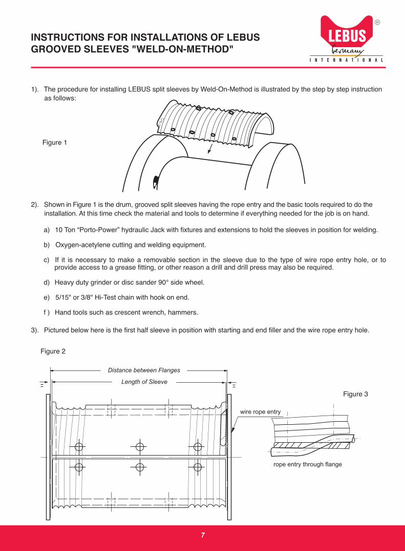
1). The procedure for installing LEBUS split sleeves by Weld-On-Method is illustrated by the step by step instruction as follows:
Figure 1
2). Shown in Figure 1 is the drum, grooved split sleeves having the rope entry and the basic tools required to do the installation. At this time check the material and tools to determine if everything needed for the job is on hand.
a) 10 Ton “Porto-Power” hydraulic Jack with fixtures and extensions to hold the sleeves in position for welding.
b) Oxygen-acetylene cutting and welding equipment.
c) If it is necessary to make a removable section in the sleeve due to the type of wire rope entry hole, or to provide access to a grease fitting, or other reason a drill and drill press may also be required.
d) Heavy duty grinder or disc sander 90° side wheel.
e) 5/15" or 3/8" Hi-Test chain with hook on end.
f ) Hand tools such as crescent wrench, hammers.
3). Pictured below here is the first half sleeve in position with starting and end filler and the wire rope entry hole.
Figure 2
7
Figure 3
rope entry through flange
wire rope entry
Length of Sleeve
Distance between Flanges

Figure 4
Place the first half sleeve in position on the drum core (the first half sleeve that has the rope entry) and align perfectly with the wire line entry hole as illustrated in Figure 2, 3 and 4.
4) Space the sleeve properly between the flanges using shims if necessary.
Caution: Use the Porto-Power Jack to hold the sleeve tight on the drum.
5) Use low hydrogen welding rod and start welding row 1 through the holes provided for plus welding as shown on figure 5. For better penetration of the weld on the drum increase the amperage slightly for plus welds.
6) Rotate Porto Jack and chain 90° to row 2, check that sleeve is tight on drum and repeat operation 5. Fill the hole flush with bottom of groove. Excess weld here will necessitate grinding smooth before using.
7) First half sleeve installation completed cleaned, and ready to receive the second half sleeve.
8
rope entry through drum core
INSTRUCTIONS FOR INSTALLATIONS OF LEBUS GROOVED SLEEVES "WELD-ON-METHOD"
Figure 5
2.
1.
3.
10T JACK
333
111

9
INSTRUCTIONS FOR INSTALLATIONS OF LEBUS GROOVED SLEEVES "WELD-ON-METHOD"
Figure 6
8) Place the second half sleeve in position making certain that it is spaced properly between flanges. Figure 5.
a) To avoid placing the second half sleeve backwards, check to see that the crossover sections are 180° apart.
b) Check also that clearance between the two sleeves is equal on each side at the split line. Gap should be approx. 5-10 mm on each side.
9) Using the hydraulic jack and extensions, position and weld second half sleeve. Weld up flush with bottom of groove. All excess welds must be grind off.
10) Now, that the welding has been completed, the installation is to be cleaned up by grinding and blending all joints into smooth grooved surface.The installation is complete and the hoist drum after painting recevied is ready to be put into service using.LEBUS counterbalance spooling.
Gap app. 5-10mm

INSTRUCTIONS FOR INSTALLATIONS OF LEBUS GROOVED SLEEVES "BOLT ON METHOD"
1) The procedure for installing LEBUS split sleeves by bolt on method is illustrated by the step-by-step instruction as follows:
Figure 1
2) Shown in Figure 1 is the drum, grooved sleeve, and the basic tools Required to do the installation. At this time check the material and tools to determine if everything needed for the job is on hand.
a) Portable electric Drill with reversing switch (for thread tapping).
b) Twist drills
c) Taps and sockets
d) Countersink usually not necessary as the grooved sleeves are shipped with the bolt holes drilled and countersunk at the factory, but will be necessary if any of the bolt holes are to be relocated, or where a removable section of the sleeve must be made at installation.
e) 10 ton "porto Jack" Hydraulic Jack
f ) Brinder
g) 5/16" or 3/8" Hi-Testchain with hook and snd.
h) Hand tools such as crescent wranch, hammers.
i ) Jigs and Fixtures, see enclosed drag.
10

INSTRUCTIONS FOR INSTALLATIONS OF LEBUS GROOVED SLEEVES "BOLT ON METHOD"
3) Pictured-figure 2 is the first half sleeve in position with starting and filler at the wire rope entry hole.
Nots: space the sleeve equally between the flanges, using shims if necessary starting and filler with rope entry hole in flange or drum core according to figure 3 or 4.
4) Before starting to drill and tap (figure 5) the middle row check carefully to see taht the sleeve is fitting tight on the drum. Insert the bolts as you complate each hole to prevent cutting from getting under sleevs.
Figure 2
rope entry
Length of Sleeve
Distance between Flanges
entry through flange entry through drum core
sleeve
starting and filler
Figure 3 Figure 4
11
LEBUS® system
cross-over section

5) Potate the drum for the next row of bolt holes Tighten the drill-base fixturs; check the sleeve for beeing down on the drum.
Note: The use of the "porto power" jack to hold the sleeve down while drilling and tapping.
6) Turn the drum to the opposite side, reset drill base fixture and drill and tap the drum. Drilling and tapping completed on the first half, the drum has been positioned and cleaned; ready to install the
second half (figure 6)
7) This sleeve is placed on the durm exercising caution to prevent this half from being put on backward. The crossover sections must be located 180° apart and the grooves must be in alignment at the split edges.
8) Repoat the drilling operation for the second half sleeve.
9) After completion of drilling and tapping, clean surface of the installed sleeves.
Figure 5
Figure 6
2.
1.
3.
crossover section
INSTRUCTIONS FOR INSTALLATIONS OF LEBUS GROOVED SLEEVES "BOLT ON METHOD"
12
10T JACK
LEBUS®
LEBUS®
1.
LEBUS®
2.
2.1 LEBUS®
LEBUS®
13
X
‘A’
‘A’
X
X X
‘B’
1
2
1
LEBUS®
2.2
a 10%b 2%
5:1 a b
3:1
2.3
LEBUS® LEBUS® LEBUS®
14
LEBUS®

‘ ’
2
3.
3.1
3.2
15
LEBUS®

4
LEBUS® LEBUS®
LEBUS®
16
LEBUS®

LEBUS®
-
-
1 2 3 4
/
1. (DIN 3051) “ ”
2. / LEBUS®
1 2
3 4
17

LEBUS®
1).
1
2). 1
a) 10 t “Porto-Power”
b) -
c)
d) 90º
e) 5/15" 3/8" Hi-Test
f )
3).
2
18
3

4
( ) 2 3 4
4) ,
“ Porto-Power ”
5) 5 1
6) Porto 90º 2 5
7)
19
5
2.
1.
3.
LEBUS®
10
333
111

20
6
8) 5
a) 180º
b) 2 5-10 mm
9)
10)
5-10mm
LEBUS®

LEBUS®
1) LEBUS®
1
2) 1
a)
b)
c)
d)
e) 10 “porto Jack”
f )
g) 5/16" 3/8" Hi-Testchain
h)
i )
21

3) 2
3 4
4) 5
2
3 4
22
LEBUS®
LEBUS® system
cross-over section

5)
“porto power”
6)
6
7) 180º
8)
9)
6
23
LEBUS®
5
2.
3.
1.
10


All Rights Reserved,Subject to Change Without Notice.

LEBUS® Product Sale and Technical Support Partner in China. LEBUS®
FOR MORE INFORMATION, LOG ON TO
WWW.LEBUS-GERMANY.COM
55 C
852-2612-0482 /2612-0481852-2612-2483
POWERTECH (CHINA) LTD.Flat C, 5/F,Cheung Kong Factory Bldg,5 Cheung Shun Street,Lai Chi Kok, Kolwoon,Hong KongTel: 852-2612-0482 /2612-0481Fax:852-2612-2483
139 , 3 31020003286-21-5039-3068/5039-307886-21-5039-3038
Shanghai Powertech Equipment Ltd.,Room 310, 3/F., 139 Pingjiang Road, Shanghai, China P.C.200032Tel: 86-21-5039-3068/5039-3078Fax:86-21-5039-3038
www.powertechchina.com
852-9408-7308
852-9134-0851
852-9351-3228
852-6286-9821
ContactsBrian Yam HK Mobile:852-9408-7308George Chen HK Mobile:852-9134-0851Steve Mak HK Mobile:852-9351-3228K.L.Yu HK Mobile:852-6286-9821
86-138-1632-197286-138-1861-748986-159-0181-1806
86-133-0160-2676 86-136-2167-7726
ContactsBrian Yam China Mobile:86-138-1632-1972W.K.Wong China Mobile:86-138-1861-7489George Chen China Mobile:86-159-0181-1806Collin Gu China Mobile:86-133-0160-2676Li-Ai Jun China Mobile:86-136-2167-7726
SD-07/09-EC
LEBUS International Engineers GmbH
Lerchenberg 10 • D-86923 Finning/GermanyPhone: +49 (0) 88 06/95 895-0 • Fax:+49 (0) 88 06/95 985-99 • E-mail:[email protected]
www.lebus-germany.com