therapeutic arm exerciser - ex n...
TRANSCRIPT
EX N’ FLEX
Therapeutic Arm Exerciser
Model EF-100 Arm/EF-100W Arm/Wrist
Instructionsfor Use
Operating Instructions
Understanding the Control Unit
The Control Unit contains all of the electronics, switches and displays necessary to control the operation of the EX N’ FLEX EF-100/100W Arm Exerciser.
* Plug the Power Cord into a 110/220 V.A.C. Wall outlet. PLEASE NOTE: Before attaching yourself or anyone to the machine, it is recommended that you read these instructions thoroughly and operate the Control Unit to familiarize yourself with the switching.*
The Main Power Switch:
The Main Power Switch is the black switch located on the right hand edge of the Control Box. When the switch is turned on the Control Unit will light up. The Power Light comes on, zeros appear in the large LED Display window and light appear in the side windows by the Mode Switch, Speed Switch and the F/Off/R Switch. (Forward, Off. Reverse).
The Pressure Switches:
There are six different Pressure Switches on the Control Unit: On/Off, a Direction Switch (F/Off/R), Mode Switch, Speed Switch and two Timer adjustment arrows.
When the side mounted Main Power Switch is on, you can start the machine by selecting forward or reverse. You can stop the machine by pressing the F/Off/R switch once to move the switch to the centre/Off position or you can also turn it off by pressing the On/Off switch on the bottom left of the face of the Control Unit, near the Power Light. If you turn it off here you will resume movement in the same direction the machine was turning when it was stopped.
Try this now: Turn on the Main Power Switch located on the right hand edge of Control Box. Press the F/Off/R Switch. The Arm Rest should begin to turn in Forward or Reverse depending on your selection. Leave the machine running then try the Speed Switch.
The Speed Switch:
The Speed Switch contains three indicator lights: Lo, Med and Hi. To choose a speed, press the switch to change between Lo, Med and Hi.Now turn the machine off by pressing the On/Off switch on the face of the Control Unit.
Understanding the Mode Switch:
The Mode switch has four positions; Timer, Biof or Biofeedback, Trip and Total. A red indicator light shows the mode being used.When the machine is first turned on the Mode Switch default position is Biof. The function of the Biofeedback display is explained further on.
The Timer Switch
Press the Mode Switch once and it will change to “Time” mode. Once in “Time” mode you can adjust/set the timer by pressing the up and down arrows. These switches are located just below the LED digital readout window. Increase the amount of time in 5 minute increments each time you press the”up” arrow. Decrease the amount of time by 1 minute, each time you press the “down” arrow. You can view the amount of time selected in the LED display window located above the arrows. When the machine is turned on the timer will begin counting down in seconds and once it reaches zero the machine will automatically shot off and the F/Off/R switch will have moved to the Centre/ Off position.Note: Once the timer is set you can switch between modes and the timer will still continue to count down.
1

Odometer “Total “ Switch:
While still in the Time mode, press the Mode Switch 3 times and you will change the mode (the red indicator light will move) to “Total”. “Total” display acts as an odometer and logs the distance travelled. The total cannot be reset and continually accumulates ”revolutions” over time. Multiply the total shown on the odometer by 1000 and divide by 2, this will give you the total number of revolutions to date.
Odometer “Trip” Switch:
Press the Mode Switch again and the red light will change the mode to “Trip”. “Trip” mode logs in revolutions. Every trip count equals 1 revolution, for example, 1 registered on the trip odometer would equal 1 revolution of the Arm Rest. To save and add the accumulated revolutions from a session to the “total” turn the machine off using the On/Off Switch on the face of the Control Unit before turning off the main power switch on the side.
Biofeedback Switch:
Press the Mode Switch again, or if the machine is turned off, turn it on and the red light will be in default Biof position. “Biof “ or Biofeedback mode displays numbers on the digital display which fluctuate between 0 and150. These numbers indicate the effort require to move a passive arm(s).
The Biofeedback mode is used to measure the User’s resistance and/or assistance. For example: if a user has tone, stiffness, or spasticity in their arm, this would cause resistance and require the motor to work harder to turn their limb. As the user becomes more relaxed and flexible the “Biof” numbers will decrease. This display enables someone with little or no feeling or voluntary movement in their limb(s) to seethat the movement is making a difference.
If the user is using the machine actively or applying some of their own strength and assisting/overriding the motor then the LED display will show a decrease in the “Biof” numbers. This shows the User/Caregiver that the User is assisting the machine and building strength. Refer to P.3 for istructions on using the machine actively.
2
0 0 10 0 1
Large Led Display
Membrane Switches (6)
Mode Switch
On/ Off Switch
Power LightF/Off/Rswitch
Side Mounted Black Switch
Timer Switches
Side Window Displays
SpeedSwitch
Control Unit
Active Mode is achieved by the User by overriding /assisting the motor (using any residual strength they have in their limbs) in either Forward or Reverse motion. The results of Active use will show on the LED Display when the Mode Switch is in “Biof” setting. Active use shows a decrease in these numbers being displayed.
The more voluntary movement applied the greater the decrease in numbers. If an individual is able to apply a consistent amount of voluntary movement with enough strength to hold the Biofeedback at 0, then it would be considered time for him/her to use a manual device ( recumbent or exercise bicycle) for exercise therapy
Instructions for use of the Active Modefor the EX N’ FLEX Arm Exercisers
Leave the machine turned on and the Motor runningActive does not mean Manual
3
IntroductionThe Ex N’ FLEX Model EF-100/100W therapeutic Arm Exerciser provides a sustained range of rhythmic movement to the muscles, joints and tendons of an immobilized arm. This machine is physically and psychologically beneficial as an adjunct to physiotherapy or where physiotherapy is unavailable.
Operating Instructions:
1. Plug Power Pack into110/220 v.a.c. Outlet.
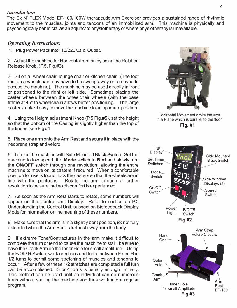
2. Adjust the machine for Horizontal motion by using the Rotation Release Knob, (P.5, Fig.#3).
3. Sit on a wheel chair, lounge chair or kitchen chair. (The foot rest on a wheelchair may have to be swung away or removed to access the machine). The machine may be used directly in front or positioned to the right or left side. Sometimes placing the caster wheels between the wheelchair wheels (with the base frame at 45° to wheelchair) allows better positioning. The large casters make it easy to move the machine to an optimum position.
4. Using the Height adjustment Knob (P.5 Fig.#5), set the height so that the bottom of the Casing is slightly higher than the top of the knees, see Fig #1.
5. Place one arm onto the Arm Rest and secure it in place with the neoprene strap and velcro.
6. Turn on the machine with Side Mounted Black Switch. Set the machine to low speed, the Mode switch to Biof and slowly turn the ON/OFF switch through one revolution, allowing the entire machine to move on its casters if required. When a comfortable position for use is found, lock the casters so that the wheels are in line with the pontoons. Rotate the arm through a further revolution to be sure that no discomfort is experienced.
7. As soon as the Arm Rest starts to rotate, some numbers will appear on the Control Unit Display. Refer to section on P.2 Understanding the Control Unit, subsection Biofeedback Display Mode for information on the meaning of these numbers.
8. Make sure that the arm is in a slightly bent position, ie: not fully extended when the Arm Rest is furthest away from the body.
9. If extreme Tone/Contractures in the arm make it difficult to complete the turn or tend to cause the machine to stall , be sure to have the Crank Arm on the Inner Hole for small amplitude. Using the F/Off/ R Switch, work arm back and forth between F and R in 1/2 turns to permit some stretching of muscles and tendons to occur. After a few of these 1/2 stretches are completed a full turn can be accomplished. 3 or 4 turns is usually enough initially. This method can be used until an individual can do numerous turns without stalling the machine and thus work into a regular program.
Horizontal Movement orbits the armin a Plane which is parallel to the floor
LargeDisplay
Side MountedBlack SwitchSet Timer
Switches
Side WindowDisplays (3)
SpeedSwitch
F/Off/RSwitch
Power Light
On/OffSwitch
Inner Holefor small Amplitude
Outer Hole
Arm StrapVelcro Closure
CrankArm
ArmRestEF-100
Mode Switch
HandGrip
4
Fig. #1
Fig.#2
Fig #3
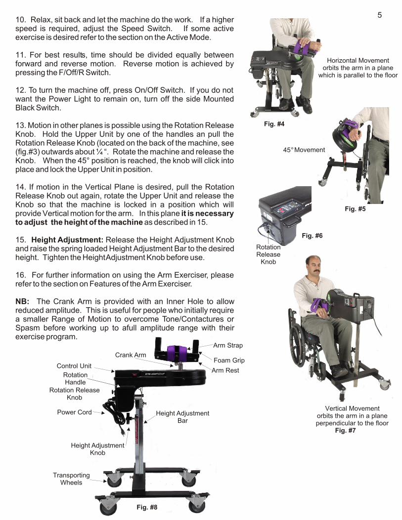
10. Relax, sit back and let the machine do the work. If a higher speed is required, adjust the Speed Switch. If some active exercise is desired refer to the section on the Active Mode.
11. For best results, time should be divided equally between forward and reverse motion. Reverse motion is achieved by pressing the F/Off/R Switch.
12. To turn the machine off, press On/Off Switch. If you do not want the Power Light to remain on, turn off the side Mounted Black Switch.
13. Motion in other planes is possible using the Rotation Release Knob. Hold the Upper Unit by one of the handles an pull the Rotation Release Knob (located on the back of the machine, see (fig.#3) outwards about ¼ “. Rotate the machine and release the Knob. When the 45° position is reached, the knob will click into place and lock the Upper Unit in position.
14. If motion in the Vertical Plane is desired, pull the Rotation Release Knob out again, rotate the Upper Unit and release the Knob so that the machine is locked in a position which will provide Vertical motion for the arm. In this plane it is necessary to adjust the height of the machine as described in 15.
15. Height Adjustment: Release the Height Adjustment Knob and raise the spring loaded Height Adjustment Bar to the desired height. Tighten the Height Adjustment Knob before use.
16. For further information on using the Arm Exerciser, please refer to the section on Features of the Arm Exerciser.
NB: The Crank Arm is provided with an Inner Hole to allow reduced amplitude. This is useful for people who initially require a smaller Range of Motion to overcome Tone/Contactures or Spasm before working up to afull amplitude range with their exercise program.
5
Horizontal Movement orbits the arm in a plane
which is parallel to the floor
Fig. #4
45O Movement
Fig. #5
Rotation Release
Knob
Fig. #6
Vertical Movement orbits the arm in a planeperpendicular to the floor
Fig. #7
Arm Strap
Foam Grip
Arm Rest
Crank Arm
Control Unit
Rotation Handle
Rotation ReleaseKnob
Power Cord Height AdjustmentBar
Height AdjustmentKnob
Transporting Wheels
Fig. #8

Instructions for Use EF-100W Arm/Wrist, Arm Cradle
Introduction: The EF-100W Arm Cradle with Wrist Attachment has two upright posts with foam grips. The hand is wrapped around the Hand Grip and rests on the 4” diameter Hand Stop. The arm rests against the other post. The following instructions will provide information in the use of this unique feature. The basic operating instructions for the EF-100/100W
, so please read that section thoroughly before proceeding to this section, the Wrist application.
1. Attach the Crank Arm to the Steel Boss protruding through hole in the Casing, first rotating the Crank Arm until the hole at the end of the Crank Arm is exposed. Then place 9/16” bolt and lock washer through hole and into the Boss. Tighten bolt securely to hold arm mechanism in place, Fig. #2.
2. Under The Arm Cradle you will see the White Wrist Movement Selection Lever (Fig.#2). This White Plate sits on a circular, slotted plate, (Fig.#1) into which 5 slots have been cut (Fig. #1). These slots are numbered from zero to four. When the Selection Lever on the White Plate is in the “ position there is no Wrist movement. In this position the Hand Grip is stationary.
4. To apply Wrist movement, lift the White Lever until the lever clears slot “0” and slide the White Lever across the Black Plate and allow the pin to drop into Slot “1”. This will provide the minimum wrist movement. Moving the lever to a slot with a higher number (ie: 2,3 or 4) increases the degree of wrist movement. It is suggested that you start with Slot 1 and work up to the other settings gradually to avoid any discomfort. The various settings may be applied before or after placing your arm in the arm Rest.
Using the Wrist/Hand Strap EF-100W Arm /Wrist
5. Attach the neoprene Hand Strap to the wrist of the affected arm and fasten around wrist (Fig # 3 ) . Secure with velcro closures.
6. Open the Arm Straps on Arm Cradle.
on the previous pages apply
0”
Second Closure of Wrist Strap(after hand is placed around Gripping Post)
First Closure of Wrist Strap
Fig #3
Hand Grip
ArmRest
ArmCradle
Arm Strap
EF-100Casing
CrankArm
Fig. #2
Boss
White Wrist movement Selection Lever
ArmStrap
HandGrip
ArmRest
Arm Cradle
Wrist Mechanism5 Adjustment slots
Control Unit
EF-100 Casing
Fig #1
HandStop
6
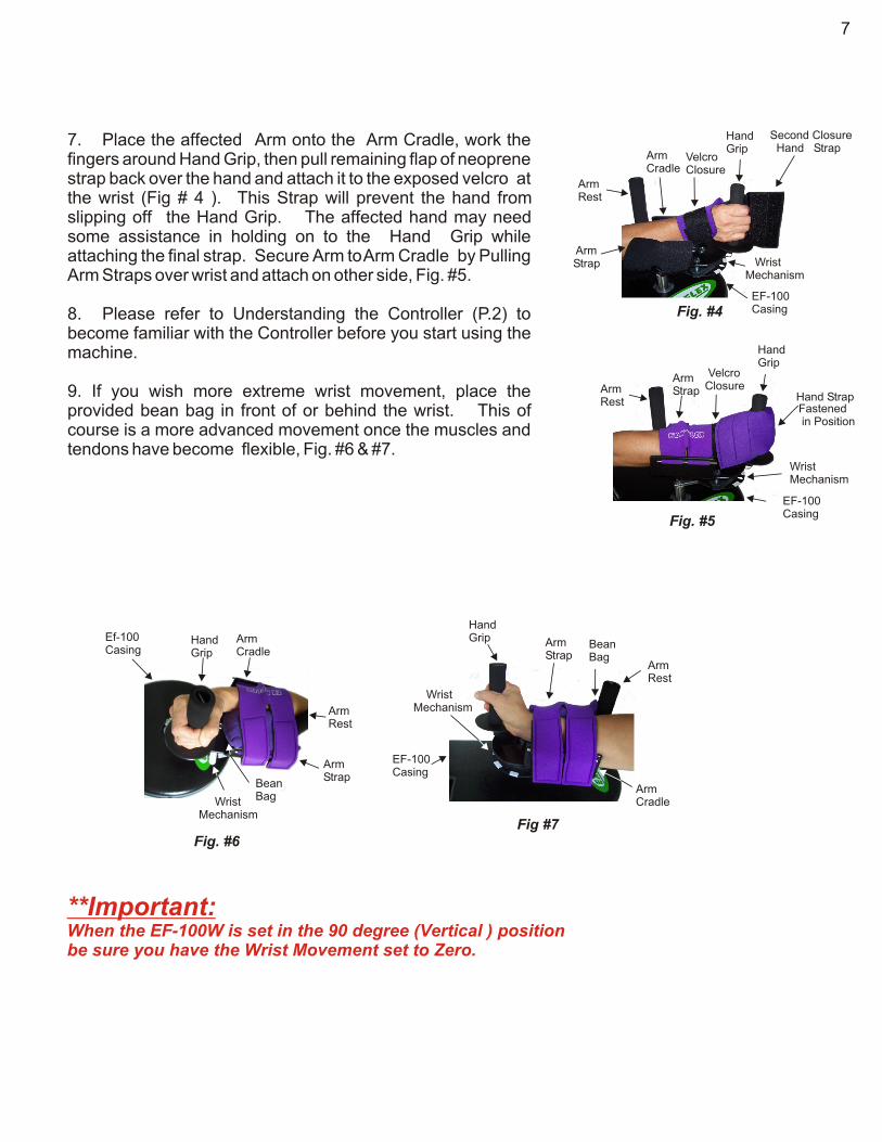
7. Place the affected Arm onto the Arm Cradle, work the fingers around Hand Grip, then pull remaining flap of neoprene strap back over the hand and attach it to the exposed velcro at the wrist (Fig # 4 ). This Strap will prevent the hand from slipping off the Hand Grip. The affected hand may need some assistance in holding on to the Hand Grip while attaching the final strap. Secure Arm to Arm Cradle by Pulling Arm Straps over wrist and attach on other side, Fig. #5.
8. Please refer to Understanding the Controller (P.2) to become familiar with the Controller before you start using the machine.
9. If you wish more extreme wrist movement, place the provided bean bag in front of or behind the wrist. This of course is a more advanced movement once the muscles and tendons have become flexible, Fig. #6 & #7.
HandGrip
Second Closure Hand Strap
VelcroClosure
ArmRest
ArmCradle
Wrist Mechanism
EF-100Casing
ArmStrap
Fig. #4
HandGrip
Arm Rest
ArmStrap
Hand Strap
VelcroClosure
WristMechanism
EF-100Casing
Fig. #5
Fastened in Position
Hand Grip
Arm Rest
Arm Strap
Bean Bag
ArmCradle
WristMechanism
EF-100Casing
Fig #7
HandGrip
Arm Rest
Arm Strap
Bean Bag
Ef-100Casing
ArmCradle
Wrist Mechanism
Fig. #6
7
**Important:When the EF-100W is set in the 90 degree (Vertical ) positionbe sure you have the Wrist Movement set to Zero.

How Long Should I Stay on the EX N’ FLEX
As with any exercise program, the best results are achieved with a gradual approach. (Resist the temptation to spend more than five minutes on the machine to start with). Slow speed is a good way to start. In extreme cases, only one or two revolutions may be achieved because of muscle/joint resistance or spasm. Sometimes by switching between Forward and Reverse and the speed switch set to High, it is possible to achieve several partial revolutions. With repeated sessions this should result in increased flexibility in the muscles and tendons to a point where full revolutions should be achieved. Any excessive resistance will show on the Biofeedback display as high numbers. As flexibility improves, the numbers shown on the Biofeedback will decrease. Once flexibility is regained and no discomfort is experienced the following day, the amount of time on the machine may be increased one minute per session to a maximum of 30 minutes per session. The time should be equally divided between Forward and Reverse. The EX N’ FLEX may be used for more than one session per day. If discomfort is experienced as a result of unaccustomed exercise, discontinue use of the machine until discomfort subsides, then resume program.
**** To assure that the arm is not over extended, make sure that the machine is close enough that the User has a partial bend in the arm at all times during use.
How to Exercise both arms at the same time:
With the machine adjusted for motion in the Horizontal plane:---- Place the unattached arm over the wrist in the Arm Cradle, so that both arms rotate together. This movement has the added benefit of providing a significant amount of Trunk movement.
---- For more shoulder movement in this plane, adjust height of machine to desired level and use from the side.
---- In the vertical plane arms must be exercised independently.
8
Features of the EX N’ FLEX EF-100 Arm/100W Arm/Wrist Exerciser
1. The arm has many more complex movements than the leg and for that reason it can initially be a little more challenging for the caregiver to position the compromised individual to the machine. It is usually necessary to work the machine into an optimum position for use by sometimes placing it either inside or outside of the wheelchair wheels. Once you have the machine in position, either in front of or beside the wheel chair and the User is comfortable you can commence operation of the machine. Follow operating instructions on previous pages. The EF-100/100W provides a wide range of movement for the arm, trunk and shoulder. We also suggest that all planes movements not be attempted on the same day. This permits the body to adjust to the different directions of movement. When a user has good flexibility all 3 planes can be used at any time. In long term care settings the machine is usually used in a single plane per day to avoid having to rotate and change the height only once on a given day.
2. Sometimes a small pillow can be use behind the individual in order to achieve the optimum position.
3. The unique Arm Rest supports frequently painful, subluxated shoulders by supporting the arm preventing sag from the shoulder.
4. The Rotation Release Knob allows the EF-100/100W machine to permit movement of the arm, trunk and shoulder in three different planes, Horizontal, 45° and Vertical.
t is necessary to adjust the height of the machine by releasing the Height Adjustment Knob and raising the Height Adjustment Bar The height may also be adjusted in the 45° mode if required. These variables provide a wide range of movement for an individual with a compromised arm.
In the Horizontal Plane an free arm may be placed over the secured arm,(Fig #4 Page 5). This provides significant trunk movement. The circular rotating motion provides a shifting of weight from one side to the other which is very helpful in establishing balance in recovering Stroke patients. This can also be achieved if the User has the ability to grip both posts and allow the arms to rotate with the posts either close to them or away from them.
5. The Arm Rest rotates either to the left or to the right .
6. The circular interface of the machine permits it to be used from any angle. The Top Unit section of the machine may be placed at any angle to the wheelchair. The base may be placed either outside the wheels of the wheelchair or one base pontoon in between the wheels. Experimentation is usually required in order to find the best position and best results for each individual.
7. The machine may be placed to the side of the wheelchair and used from this position for 45° or Vertical movement.
8. The machine may also be placed at the side for use in the Horizontal plane.. In this position increased shoulder movement may be obtained.
9. The EF-100/100W is very mobile and easily moved from place to place. It is easily locked into position with locking castor wheels.
10. Full Biofeedback features are available on this machine.
When using the In the Vertical mode i
9
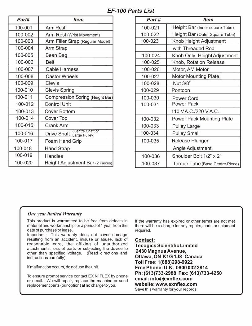
100-001 Arm Rest
100-002 Arm Rest (Wrist Movement)
100-003 Arm Filler Strap (Regular Model)
100-004 Arm Strap
100-005 Bean Bag
100-006 Belt
100-007 Cable Harness
100-008 Castor Wheels
100-009 Clevis
100-010 Clevis Spring
100-011 Compression Spring (Height Bar)
100-012 Control Unit
100-013 Cover Bottom
100-014 Cover Top
100-015
Part# Item Part # Item
EF-100 Parts List
This product is warranteed to be free from defects in material and workmanship for a period of 1 year from the date of purchase or lease.Important: This warranty does not cover damage resulting from an accident, misuse or abuse, lack of reasonable care, the affixing of unauthorized attachments, loss of parts or subjecting the device to other than specified voltage. (Read directions and instructions carefully).
If malfunction occurs, do not use the unit.
To ensure prompt service contact EX N’ FLEX by phone or email. We will repair, replace the machine or send replacement parts (our option) at no charge to you.
If the warranty has expired or other terms are not met there will be a charge for any repairs, parts or shipment required.
Contact:Tecogics Scientific Limited 2430 Magnus Avenue,Ottawa, ON K1G 1J8 Canada Toll Free: 1(888)298-9922Free Phone: U.K. 0800 032 2814Ph: (613)733-2988 Fax: (613)733-4250email: [email protected]: www.exnflex.comSave this warranty for your records
One year limited Warranty
100-016
100-017
100-018
100-019
100-020
100-021
100-022
100-023
100-024
100-025
100-026
100-027
100-028
100-029
100-030
100-031
100-032
100-033
100-034
100-035
100-036
100-037
Crank Arm
Drive Shaft(Centre Shaft of Large Pulley)
Foam Hand Grip
Hand Strap
Handles
Height Adjustment Bar (2 Pieces)
Height Bar (Inner square Tube)
Height Bar (Outer Square Tube)
Knob Height Adjustment
with Threaded Rod
Knob Only, Height Adjustment
Knob, Rotation Release
Motor, AM Motor
Motor Mounting Plate
Nut 3/8”
Pontoon
Power CordPower Pack
110 V.A.C./220 V.A.C.
Power Pack Mounting Plate
Pulley Large
Pulley Small
Release Plunger
Angle Adjustment
Shoulder Bolt 1/2” x 2”
Torque Tube (Base Centre Piece)