theory of reverse combustion linking
TRANSCRIPT

Theory of reverse combustion linking
M.S. Blinderman
Ergo Exergy Technologies Inc., CANADA
A.Y. Klimenko 1
School of Engineering, University of Queensland, AUSTRALIA
Abstract
The present work suggests a theory of Reverse Combustion Linking (RCL). RCL isa central unit operation of Underground Coal Gasification (UCG) technology. Thetheory is based on analysing stability of different branches of the propagation speedcurves and determining the regime that is responsible for propagation of the flameduring RCL. The theory is in a good qualitative and quantitative agreement withthe data obtained in practical use of RCL in UCG operations.
Key words: Undeground Coal Gasification, Reverse Combustion Linking
1 Introduction
Reverse combustion linking (RCL) is a key operation of Underground Coal Gasification(UCG, [1,2]). The term ”reverse combustion linking ” became conventional in UCG appli-cations and we follow this convention in the present work. UCG is a gasification processcarried on in non-mined coal seams using injection and production wells drilled from thesurface, which enables the coal to be converted into product gas. RCL is a method oflinking the process wells within a coal seam, which includes injection of an oxidant intoone well and ignition of coal in the other so that combustion propagates towards thesource of oxidant thereby establishing a low hydraulic resistance path between the twowells as shown in Figure 1. This allows to inject an oxidant and produce synthesis gas atcommercially significant flow rates. A procedure to conduct RCL includes the following:an oxidant is injected in one of the wells (injection well) while coal seam is ignited in theother well (production well). Combustion of coal in the production well proceeds towardsthe source of oxidant. Injection of oxidant into the injection well is maintained until thefire reaches the bottom of the well. Creation of a low hydraulic resistance link between the
1 corresponding author E-mail: [email protected]
Combustion and Flame 150 (2007) 232-245 doi:10.1016/j.combustflame.2006.12.021

bottoms of the process wells results in significant drop in the pressure difference betweenthe wells indicating successful completion of the linking process. RCL is followed by mainstages of UCG that are not considered in the present work. RCL is conventionally charac-terised by the speed of linking measured in meters per day and by oxidant consumptionmeasured in normal cubic meters per hour.
Among a number of publications devoted to reverse combustion in porous media [1,3–6],only the analytical work of Britten and Krantz [1] is specifically devoted to RCL. In thiswork, Britten and Krantz considered RCL while solving a set of modelling equations for aplanar reverse combustion front and focusing their attention on the equations for the gasphase, implicitly assuming deficiency of air and excess of coal in the reaction zone anddownstream from it. Although their approach confirmed hydrodynamic instability of thefront, which is an important factor in the link formation, the conceptual understanding ofRCL employed by Britten and Krantz contradicts empirical evidence. They consider RCLas the process of coal pyrolysis followed by combustion of the released volatile matterso that the hydraulic link between injection and production wells is formed by a porouspath of an enhanced permeability. However, empirical data from UCG operations indicatethat RCL results routinely in formation of a channel in which coal has been essentiallyconsumed by combustion.
In our approach we, to a large extent, follow the principle formulation of reverse combus-tion introduced by Schult et al [5] and used in the recent work of Liu et. al. [6]. Unlikethe formulation of Britten and Krantz [1], the formulation of Schult et al [5] allows foranalysis of both oxigen-deficient and coal deficient flames. We assume, however, as didBritten and Krantz [1], that gas phase in the reaction zone is not dominated by diffusion.We analyse both oxygen-deficient and coal-deficient cases and their hydrodynamic andpulsating stability and pay special attention to the vicinity of the stoichiometric point. Asthe result of the analysis, we found that the flames close to the stoichiometric regime (asdefined for incomplete combustion) are primarily responsible for RCL. Another feature ofthe present work is consideration of curved flames and their propagation speed, which isimportant for understanding of RCL. It is treated using Intrinsic Disturbed Flame Equa-tions (IDFE, [7–10]). Although in most of the paper we implicitly follow the developedasymptotic methodologies, at several instances we opted for a simplified (rather than strictasymptotic) formulation that allows to obtain compact analytical representations of theresults but does retain the important physical effects that are of primary importance inRCL. This approach resulted in an overall theory of reverse combustion linking duringUCG that determines main relationships between key parameters of the process. Prelim-inary results of applying the theory to specific UCG conditions demonstrate a reasonableconformity with the data obtained in practical UCG operations.
2

2 The modelling equations
The equations governing transport and reactions in porous media are represented by theconservation of mass, energy and species equations that can be written in the form
∂ρ
∂t+∇·(m) = 0,
∂ρi∂t
+∇·(mi) = Wi (1)
∂ρh
∂t+∇·(mh)−∇· (λ∇(T )) = 0 (2)
Here, m ≡ ρv and mi = viρi are the mass fluxes, the subscript index ”i” runs over allspecies of interest; ρi is the density (mass per volume) of the specific component (so thatYi = ρi/ρ is the mass fraction), λ is the effective heat conductivity and Wi is the chemicalreaction source terms of the i’th component. The mass flux ρv is denoted by m. Thetemporal pressure derivative ∂p/∂t is conventionally neglected in the energy equation.The over-bar denotes the superficial averages:
m = φgmg + φqmq + φsms =∑i
φimi =∑i
φiρivi
mh = φgmghg + φqmqhq + φsmshs =∑i
φimihi
The superficial averages can be evaluated as the sum over parameters of the three phases– gas, liquid and solid – that are denoted by the subscript indices ”g”, ”q” and ”s”. Thespecific volumes φ occupied by the phases are determined by the porosity of the solidphase. The superficial averages can also be evaluated as a sum over all species involved.The species are indexed by the running index ”i” but we should note that velocities vand specific volumes φ are the same for all components of a given phase, although vand φ are, generally, different for different phases. For example, vi = vg 6= vs for any”i” that belongs to the gas phase. The averages that are applied to a single componentsuch as mi = φimi = φiρivi do not involve summation over the other species. Similarly,mg = φgmg = φgρgvg for the gas phase and other phases. The temperature T is consideredto be the same for all phases and does not need averaging. We do not consider variationsof the values in the interparticle space. Hence, the intrinsic averages simply coincide withthe values determined within a specific phase and no special notation is needed here forintrinsic averages. The momentum equation is represented by the Darcy law
vg = U + S, U = −f∇p (3)
where S is the velocity associated with the moving frame of reference (i.e. the flamespeed) and f is permeability.
In the present analysis we do not consider the liquid phase separately, assuming that theunderground water is supplied with the gas flow or represents the coal moisture content.Hence only two phases, gas and solid, need to be indexed explicitly. In terms of the phasesthe global reaction takes the form
µ−g (Gas)− + µ−s (Solid)− → µ+g (Gas)+ + µ+
s (Solid)+
3
or ∑i
µ−i (Species)i →∑i
µ+i (Species)i
The coefficients µi are on the mass basis. The superscripts ”−” and ”+” denote valuesbefore and after reactions and µ+
i −µ−i represents the mass change of ith component. In therest of the paper we put µ−g = 1 without loss of generality. The global reaction is presumedto be specified so that the products coefficients depend on µ−s so that µ±i = µ±i (µ−s ) forany component ”i” (or phase ”i”). All of the reactions are presumed to form a globalreaction that has a single rate so that we can write for any i and j
Wi
µ+i − µ−i
=Wj
µ+j − µ−j
The total enthalpy hi of each component can be represented as a sum of sensible enthalpyand enthalpy of formation hi = h
(s)i +h
(f)i with the superscripts ”s” and ”f” denoting the
sensible and formation enthalpies. The enthalpy equation takes the form
∂ρh(s)
∂t+∇·(mh(s))−∇· (λ∇(T )) = Wh (4)
where
−Wh ≡∂ρh(f)
∂t+∇ · (mh(f)) =
∑i
h(f)i
(∂ρi∂t
+∇·mi
)=∑i
h(f)i Wi = qWO2,
q ≡ H(µ−s )
µ−O2 − µ+O2
, H(µ−s ) ≡∑i
(µ−i − µ+
i
)h
(f)i (5)
and H(µ−s ) is the enthalpy of the reaction. The enthalpy of formation is defined as theenthalpy at a certain reference temperature T (f) whose conventional value is 250C. (Thebest choice for T (f), which accurately defines the heating value of the reaction, is a constanttemperature that is close to the temperature in the reaction zone). Multiplying equations
for the each component in (1) by (h(s)i ) = h
(s)i (Tu), evaluating the sum over all ”i” and
subtracting the result from equation (4) yields the equation for the sensible enthalpy
increments ∆h(s)i
∂ρ∆h(s)
∂t+∇·(m∆h(s))−∇· (λ∇(T )) = Wh +W
(s)h (6)
where
∆h(s)i ≡ h
(s)i − (h
(s)i )u; W
(s)h ≡ −
∑i
Wi(h(s)i )u
The additional term W(s)h can be nullified by selecting T (f) = Tu.
4

3 Planar flame
A simple, planar flame front propagating under stationary conditions is characterised bythe following system of equations
∂m
∂x= 0,
∂mi
∂x= Wi (7)
∂mh
∂x− ∂
∂x
(λ∂T
∂x
)= 0 (8)
Here, we use the system of coordinates that is attached to the flame; for the first compo-nents of vectors that is normal to the flame front – x(1), v(1), m(1) and others – the indexidentifying the normal component is omitted here and further in the article. Integrationof these equations across the flame yields
(m)b = (m)u (9)
(mi)b = (mi)u +Qi, Qi ≡∫ +∞
−∞Widx (10)
(mh)b = (mh)u (11)
The subscript ”u” is used to denote values upstream from the flame while the subscript”b” denotes values downstream from the flame front. Equations (4) and (11) can bewritten as
∂mh(s)
∂x− ∂
∂x
(λ∂T
∂x
)= Wh (12)
(mh(s))b = (mh(s))u +Qh (13)
where equations (5) indicate that
Qh ≡∫ +∞
−∞Whdx = (mh(f))u − (mh(f))b = (mg)uH(µ−s ) (14)
3.1 The reaction zone
The major reaction in the global reaction mechanism is oxidation of carbon
C + (1− n/2) O2 → nCO + (1− n) CO2
that is expected to be incomplete when n < 1. The reaction machanism may also includeother reactions and phase transitions (evaporation of water, for example, has a significanteffect on the flame temperature), although the rate of the major reaction is presumed todetermine all other reactions and phase transitions. The rate of the major reaction thatdetermines consumption of oxygen is given by
WO2 = −ϕ(ρC)AρO2K(T );1
K(T )=
1
Kr(T )+
1
Kt
, Kr(T ) = exp (−TE/T ) (15)
5
For temperatures lower than Tt specified by Kt = exp (−TE/Tt) , the rate is reaction-limited K ≈ Kr and, for the temperatures higher than Tt, the rate is transport-limitedK ≈ Kt. The reaction parameter A is presumed constant while ϕ = 1 when ρC > 0 andϕ = 0 when ρC = 0. Assuming that the reaction zone is thin in comparison with the flamethickness, we obtain
∂m
∂x= 0,
∂mi
∂x= Wi (16)
− ∂
∂x
(λr∂T
∂x
)= Wh (17)
The integral of the enthalpy equation is given by
(λT ′)(−r) = Qh = (mh(f))(−r) − (mh(f))b (18)
The subscript ”r” is used to denote the values related to the reaction zone, for example,λr is the diffusion coefficient within reaction zone that, conventionally, can be assumedto be constant λr = λb since the reaction zone is presumed thin. The subscript andsuperscript indices ”−” are used to emphasise that the indexed values are related to thereactants while the index ”+” points to the products. To make equations concise, weintroduced T ′ ≡ ∂T/∂x.The reaction rate for the heat release is linked to the reactionrate by qWO2 = −Wh where the coefficient q = q(µ−s ) = H(µ−s )/(µ−O2 − µ+
O2) representsheat released by oxidation with one unit of mass of O2. Hence, with the use of (15) wemay write
∂λrT′
∂x= q
∂φgvgρO2
∂x= −qϕAρO2K(T ) (19)
Since (T ′)(+r) = (T ′)b = 0, we use the following linear dependence between T ′ and ρO2
ρO2 = ρO2(T ′) = (ρO2)b + (ρO2)∆
T ′
(T ′)(−r)(20)
Here and further in the paper we denote (·)∆ ≡ |(·)u − (·)b|. Linear function (20) rep-resents an exact integral if φgvg = const through the reaction zone and this is the casewhen the reactions do not change number of moles in the gaseous phase (for example,C+O2 →CO2) in other cases the linear dependence represents an approximation that isphysically plausible and, at the same time, ensures reasonably simple integration of (19).Multiplying (19) by T ′ and separating variables leads to
λrqϕA
T ′ dT ′
ρO2(T ′)= −K(T )dT (21)
Evaluating of the integrals
∫ T ′(−r)
0
T ′dT ′
ρO2(T ′)=
(T ′(−r)
)2
(ρO2)∆
(1− ξ) (22)
Φ(Tb) =∫ Tb
−∞K(T )dT =
Kt
Zln
(1 +
Kr(Tb)
Kt
)(23)
6

where
ξ ≡ (ρO2)b(ρO2)∆
ln
((ρO2)u(ρO2)b
), Z ≡ TE
T 2b
(24)
is performed by expanding the exponent exp (−TE/T ) = exp (−TE/T0 + Z(T − T0)) invicinity of a certain reference temperature T0 that is selected close to Tb. In evaluations ofthe RCL rates presented below we assume T � Tt, henceKr � Kt and Φ(Tb) = Kr(Tb)/Z.Finally, we note that Qh = qQO2 and obtain
Qh(Tb, ...) = λrT′(−r) =
√(ρO2)∆ qAλr
1− ξΦ(Tb) (25)
3.2 The planar flame speed
The speed of the planar flame can be obtained without specific analysis of the preheatzone. We first note that the reaction coefficients are linked to the mass fluxes by theequations
µ−g = 1, µ+i =
(mi)b(mg)u
, µ−i =(mi)u(mg)u
(26)
for any i representing different species or phases. Equation (11) divided by (mg)u indicatesthat the enthalpy is preserved∑
i
µ+i hi(Tb) =
∑i
µ−i hi(Tu) =⇒ Tb = Ta(µ−s , ...) (27)
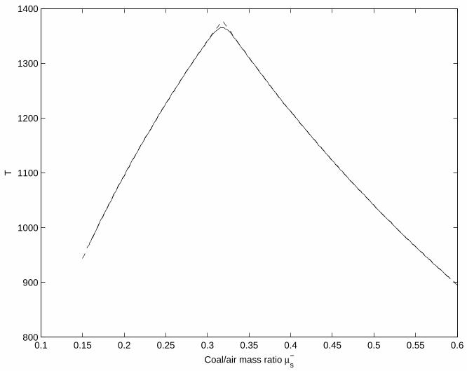
This determines the temperature of the products Tb as the adiabatic temperature Ta forgiven fuel/air ratio µ−s . Dependence of Tb on µ−s for the conditions analysed in Section 6is shown in Figure 2. Equation (14) determines the gas and solid mass flow rates
(mg)u =Qh(Tb, ...)
H(µ−s ), (ms)u = µ−s (mg)u (28)
and the flame and gas velocities
S = vs =(ms)u
(φsρs)u, (vg)u = Uu + S =
(mg)u(φgρg)u
(29)
The flame speed strongly depends on the temperature of the products Tb which, in itsturn, strongly depends on fuel/air ratio µ−s . The functions Ta(µ
−s , ...) and Qh(Tb, ...) also
depend on other parameters such as Tu, A, TE and initial compositions of coal and airthat are fixed and selected to match the conditions in the coal seam.
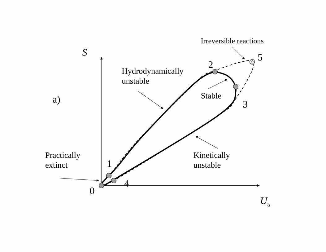
The dependence of the flame speed S on the gas velocity in the fresh mixture Uu is shownin Figure 3. In Figures 2 and 3, the dashed curve corresponds to irreversible reactions witha jump in the slope of the curve at point 5 that corresponds to the stoichiometric air/fuelratio (for a given proportion n between CO and CO2 in the reaction products). This jumpis induced by the jump in the slope of the adiabatic temperature function Ta(µ
−s ). Two
propagation speeds correspond to the upper and lower branches of the curve and a single
7
given value of Uu. The upper branch of the curve is oxygen-deficient and it is hotter thanthe lower branch that is coal-deficient. The temperatures near the point 0 are low, theflame speed is small and the flame becomes practically extinct. The flame can not besustained and is blown off by any flow with a gas velocity that is higher than (Uu)5 (i.e Uuat point 5) The stability analysis presented in the appendix indicates that the lower branchis unstable due to pulsating instability. The flames that correspond to this branch eitherrapidly accelerate and reach the upper branch or decelerate and become extinct. The roleof this branch is more in separating the flames that are sustainable from the flames thatare extinguished. The upper branch is also not stable – it is affected by the hydrodynamicinstability that is less severe than the pulsating instability. Our assessment of the stabilityof RCL is, generally, in agreement with the other works on reverse combustion [1,5,6,11].The details of the stability analysis are given in the Appendix.
As we show in the next sections, the vicinity of the stoichiometric point 5 in Figure 3plays a major role in RCL but the dashed curve does not allow to analyse the details ofthe stoichiometric point. In a more realistic case, Ta(µ
−s ) appears to be smoothed near
the stoichiometric point and this case corresponds to the solid curves in Figures 2 and3. One can notice that instead of the single maximum velocity point, we now have twomaximum points: point 2 where the flame speed S reaches its maximum (S)2 (and BU = 0in (A.5)) and point 3 that corresponds to the maximal value of the gas velocity (Uu)3 (andBS = 0 in (A.5)). The stability analysis shows that the branch between points 0 and 2 ishydrodynamically unstable, the branch between points 3 and 0 is unstable due to pulsatinginstability while the section of the curve between points 2 and 3 is stable. The vicinity ofpoint 2 can be considered as practically stable due to obvious physical limitations imposedon the scale of the disturbances so that k in equation (A.19) of the appendix can not beinfinitely small. Point 3 represents the most stressed regime of the flame separating thesutained flame from the flame blow-off and point 3 is therefore unstable for practicalpurposes.
4 Disturbed flame
The Intrinsic Disturbed Flame Equations (IDFE) is an asymptotic methodology of analysingstructure of the flame fronts curved and stretched by surrounding flow. IDFE were firstintroduced in Ref [7]. The main features of IDFE is using specially selected adaptive curvi-linear system of coordinates attached to the flame that radically simplifies formulation ofthe problem. In curvilinear system of coordinates, differential equations involve g2 — thedeterminant of the metric tensor that defines local metrics of the curvilinear coordinates.The IDFE coordinates are selected so that g is proportional to the area of a flame surfacesegment. As discussed further in this section, the value of g is determined by two majorparameters: the spatial derivative of g, which is related to flame curvature γ, and thetemporal derivative of g, which is related to the flame stretch κ The most useful featureof IDFE is that only two parameters characterising flame/flow interactions (γ and κ) enterthe transport equations from early stages of problem formulations. Several results havebeen obtained with the use of IDFE technique. If any multistep reaction kinetics occurs in
8

a zone, which is thin in comparison with the flame width, then γ does not explicitly appearin the disturbed flame speed equation [8] but, if the reaction zone is thick, γ is, generally,present in the flame speed equation [9]. IDFE have been used to formulate a unifyingapproach to determining the speed of disturbed flames [7,10], to establish effective flamejump conditions for scalars and velocities [10] and to analyse stability of premixed flames[12].
Here we use IDFE to take into account the effects of flame stretch and curvature as wellas some of unsteady effects. In a general curvilinear system of coordinates the transportequations (1), (2) and (4) take the form
∂gρ
∂t+∂gmj
∂xj= 0 (30)
∂gρi∂t
+∂gmi
j
∂xj= gWi (31)
∂gρh
∂t+∂gmjh
∂xj− ∂
∂xj
(gjkgλ
∂T
∂xk
)= 0 (32)
∂gρ∆h(s)
∂t+∂gmj∆h(s)
∂xj− ∂
∂xj
(gjkgλ
∂T
∂xk
)= gWh + gW
(s)h (33)
where g =∣∣∣det gjk
∣∣∣−1/2, gjk is the metric tensor of the of coordinates, the superscript
indices run over spatial components of the vectors j, k = 1, 2, 3 and the summation con-vention is applied to repeated indices. The most convenient choice of the coordinate systemused in IDFE enforces that x1 is perpendicular to the flame (so that g12 = g13 = 0);x1 has the same scaling as the physical coordinate g11 = g11 = 1 and the coordinatesystem is attached to the flame so that x1 = 0 determines the flame (i.e. reactionzone) location [7,8]. In the rest of the paper x1 is denoted simply as x. The operator∇f denotes the 2-dimensional divergence evaluated on the flame surface, for example∇f · (gm) ≡ ∂(gmα)/∂xα, where α = 2, 3 runs over the coordinates on the flame surface.Although in the case of a single phase the 2-dimensional divergence term can be removedby selecting the proper stretch rate for the flame surface coordinates x2 and x3 [7,8], themultiphase case requires explicit specification of the surface divergence since the rate canbe different for different phases. The transport equations can now be written as
∂gρ
∂t+∇f · (gm) +
∂gm
∂x= 0 (34)
∂gρi∂t
+∇f · (gmi) +∂gmi
∂x= gWi (35)
∂gρh
∂t+∇f · (gmh) +
∂gmh
∂x− ∂
∂x
(gλ∂T
∂x
)− ... = 0 (36)
∂gρ∆h(s)
∂t+∇f · (gm∆h(s)) +
∂gm∆h(s)
∂x− ∂
∂x
(gλ∂T
∂x
)− ... = gWh + gW
(s)h (37)
The triple dots indicate neglecting tangential heat fluxes that are small in thin flames(the major tangential heat losses are taken into account by using the intrinsic curvilinear
9

system of coordinates [7,8]). Integration of equation (37) across the flame results in(m(h(s) − h(s)
u ))
(+r)= Qh −
∑i
Qi(h(s)i )u −Ql (38)
where
Ql ≡1
gr
∫ x(+r)
−∞
(∂gρ∆h(s)
∂t+∇f · (gm∆h(s))
)dx (39)
is the rate of heat loss, g = gr is x-independent within the reaction zone (but not every-where within the flame) ∫ x(+r)
−∞gWidx = grQi, (40)
and the values Qi are the same as defined in (10). The subscript ”+r” indicates thepoint at the end of the reaction zone rather than any point in the burned mixture. Thisdistinction is needed since m is not necessarily a constant in the burned region due topossible variations of g. The reaction zone is thin and, to the leading order, is not affectedby the disturbances and the unsteady effects so that, within the reaction zone, the functiong = g(x, t) can be replaced by a single value gr(t). We also need to introduce the projectedmass fluxes m∗i that coincide with mi within the reaction zone, but m∗i remain constantoutside the reaction zone. Thus the projected mass fluxes can be defined as satisfying∂m∗i /∂x = Wi so that (m∗i )b − (m∗i )u = Qi. Multiplying the last equation by h
(f)i and
evaluating the sum over all i results in the relationship
(m∗h(f))b − (m∗h(f))u = Qh =(m∗g)uH(µ−s ) (41)
that is similar to (14). The equation for the sensible enthalpy is, however, directly affectedby the flame stretch: with the use of the projected mass fluxes, equation (38) can be writtenas (
m∗h(s))b−(m∗h(s)
)u
= Qh −Ql (42)
The difference of (42) and (41) represents the equation for the total enthalpy(m∗h
)b−(m∗h
)u
= −Ql (43)
so that ∑i
µ+i hi(Tb) =
∑i
µ−i hi(Tu)−Ql
(m∗)u(44)
and
Tb = Ta(µ−s , ...)− δTl, δTl =
Ql(m∗Cp
)b
(45)
where the last equation is based on the assumption that a constant heat capacity can beused to characterise the mixture between the actual post-burn temperature Tb and theadiabatic temperature Ta. The heat release rate is determined by equation (25), which isnot affected by the stretch due to thinness of the reaction zone, and, for given Qh, theflame speed is determined by (41) in accordance with (29).
The asymptotic value of the integral Ql defined by (39) is now evaluated. This integral isconsidered to be a correction so that it can be represented as a sum of the terms and each
10

of this terms is linear with respect to the cause of the heat loss. The non-linear terms aresmaller than the leading linear terms and are therefor neglected. It should be noted thatsmall variations of the temperature Tb can result in significant changes of Qh(Tb, ...) and Sdue to a high activation energy of the reaction. First we expand g = gr(1−γ0x+κ0t) + ...where
γ0 = −(∂ ln g
∂x
)r
, κ0 =
(∂ ln g
∂t
)r
(46)
are the flame curvature and the flame stretch, evaluated at the surface of the most intensereactions. If the surface coordinates do not expand, we can distinguish the overall stretchκ0 from the ”phase-specific” stretches κi
κ0 = Sγ0, κi = ∇f · (vi) (47)
The stretch κ0 is induced by the flame curvature γ0 and is the same for all phases whileκi are phase-specific and occur when the flow of a particular phase (or mixture com-ponent) diverges on the flame surface. Within the preheat zone, κi is assumed constant(i.e. permeability and absolute viscosity determining f in Darcy’s law are presumed tobe temperature-independent). The unsteady effects (which would result in replacement
of κ0 by κ0 + d/dt) are considered separately in Appendix and neglected here. Since h(s)i
does not depend, to the leading order, on the surface coordinates x2 and x3, equation (39)takes the form
Ql ≡∫ xr
−∞
(κ0ρ∆h(s) + κρ∆h(s)
)dx = (κ0 + κ)I =
∑i
(κ0 + κi)φiIi (48)
where
Ii =∫ xr
−∞ρi∆h
(s)i dx =
∫ Tb
Tu
ρi∆h(s)i λ
m∗∆h(s)dT (49)
The integrals Ii are mainly dependent on conditions in the preheat zone and, since thereaction zone is thin, can be evaluated with the upper limit just before or just after thereaction zone, whichever approach is more convenient. In the preheat zone where Wh = 0,as it follows from equation (12) the link between the differentials dT and dx is given byλdT = m∗∆h(s)dx. Estimations of the integrals Ii result in the following expression forthe temperature loss
δTlT∆
= γ0lfθs + κglfθgUu
, (50)
where
θs ≈
(m∗s(Cp)s
)u(
m∗Cp)u
, θg ≈
(m∗g(Cp)g
)u(
m∗Cp)u
, lf ≡∫ xr−∞ (T − Tu) dx
Tb − Tu≈ λr
(mCp)u
and T∆ = Tb − Tu. In these estimations we assume constant heat capacities and put(m∗Cp
)u≈(m∗Cp
)b. This assumption is valid as long as the heat effect of the reaction
does not depend strongly on the temperature. The flame thickness can be defined dif-ferently for different components li = Ii/(ρi∆h
(s)i )b but any li can be approximated by
lf .
11

5 Reverse combustion linking
In order to understand the complexity of the RCL process we first note that the planarreverse combustion flame would be very difficult (and probably impossible) to sustain.Indeed, there is only a small region between points 2 and 3 that can correspond to thisregime and be stable. The gas velocity Uu must be homogeneous and accurately controlledso that (Uu)2 < Uu < (Uu)3. Practically, any noticeable increase in Uu will lead to theflame blow off while any decrease in Uu will cause development of instabilities curving theflame.
Similar consideration can be applied to the reverse combustion in a channel that wouldbe inevitably formed due to the instabilities even if the initial conditions correspond toa planar flame. The gas velocity in the channel can’t be much greater than (Uu)2 (andnever exceeds (Uu)3), since the flame would be blown off, or noticeably smaller than(Uu)2, since this would leave too much space for development of instabilities that wouldeffectively narrow the channel. The channel width that, for a given total mass flow of thegas phase Mg, corresponds to gas velocity of (Uu)2 is the width that would be “preferred”by the process. Under these conditions, the flame can be still treated as oxygen-deficientbut nearly all coal within the channel is oxidised in the process. We, however, find anew complication: the speed of (Uu)2 is not a constant and would in its turn dependon the channel width. A narrower channel has a more significant heat loss and a lowertemperature in the reaction zone and this results in lower (Uu)2 and S2. This loss wouldoccur at least because the flame in the channel has a convex shape and, in accordancewith the IDFE analysis of the previous section, a lower propagation speed. There are alsoother possible reasons for the temperature decrease in narrow channels (such as groundwater influx from coal around the channel and lateral heat loss). Greater Mg correspondsto wider channels and greater flame speeds. Very large Mg corresponds to minimal lossesand any further increase in Mg would not speed up the flame but only widen the channel.An insufficient Mg results in excessive heat loss and flame extinction.
In reality, the RCL process is even more complicated. It is inevitable that the qualityand porosity of coal in the seam varies from point to point resulting in variations ofthe propagation speed. Let us assume that the channel radius Rc is somewhat above the“preferred” value so that Uu is below (Uu)2. Due to hydrodynamic instabilities, this wouldresult in development of a small cavity. The tip of the cavity, called the leading point, hasa radius Rp that is smaller than Rc while the local velocity at the tip is (Uu)2. The leadingpoint propagates faster and is followed by sloping conical flame whose normal propagationvelocity is below that of the leading point. The ratio Rp/Rc can not be too small since thiswould result in excessively high gas velocities at the leading point and a slow propagationspeed or extinction of the tip. If the leading point propagates forward too fast the cavitybecomes deep and narrow and this attracts additional gas flow through the leading pointso that gas velocity exceeds (Uu)2. The leading point is then slowed down and forcedto wait until combustion behind the leading point widens the cavity. The leading pointcan also be extinguished by excessive local gas velocity or other unfavourable conditions.As the rest of the channel catches up with the leading point, the front surface of thechannel flattens until conditions favourable for the development of a new leading point
12

are attained. It should be noted that not only one but several leading points competingfor the gas flow can develop at the same time. The leading point that is closer to thesource of the air and/or has better local conditions for the flame propagation is morelikely to “win” and lead further channel formation.
Compared to the reverse combustion in a planar flame, the RCL process in a channelhas an important stabilising mechanism. If the gas velocity is close to or somewhat above(Uu)3, the propagation of the flame is arrested but the flame in the channel is not com-pletely blown off: continuing burning behind the leading point would widen the channeluntil the gas velocity drops to a more acceptable level. An excessively high (Uu)3 can stillterminate RCL. If the channel is too wide and (Uu)3 is too small for given Mg, the rapidlyadvancing leading point would make the following sections of the channel narrower sothat (Uu)3 in these sections becomes higher.
Assuming that linking forms a channel whose radius is Rc and since S � Uu we may write
(mg)u =Mg
πR2c
(51)
The temperature loss δTl = Ta − Tb appears mainly due to the flame curvature γ0 at theleading point γ0 = 2/Rp = 2ζ/Rc where Rc and Rp are connected by a constant factorζ that must be not less than unity: Rc = ζRp. Since RCL is close to the stoichiometricregime and coal is fully consumed (or nearly fully consumed) within the forming channel,the gas velocity is directed perpendicular to the flame and κg = 0 does not contribute tothe flame stretch. Hence, equation (50) yields
Tb = Ta(µ−s )− 2
θT∆lfRp
= Ta(µ−s )− 2ζθT∆lf
√√√√π (mg)uMg
(52)
At the leading point, the mass flow rates and the flame speed satisfy the following
(mg)uH(µ−s ) = Qh(Tb, ...), (ms)u = (mg)u µ−s , S =
(ms)u(φsρs)u
(53)
According to the previous analysis, the S — the velocity of propagation of the leadingpoint — is treated as the value estimating the overall linking speed.
6 RCL in Chinchilla UCG operations
The UCG process developed and practiced by Ergo Exergy Technologies is called Ex-ergy UCG or εUCG. εUCG was applied in the Chinchilla site near Brisbane (Australia)owned by LINC Energy Ltd. (Blinderman and Jones (2002)). RCL has been one of themethods applied in Chinchilla Project to achieve linking of the process wells. Nine pro-cess wells have been successfully connected by RCL. The well spacing varied between 15and 60 m, and RCL at the Chinchilla UCG plant demonstrated linking speeds between0.9 m/day and 11.3 m/day. The wide range of RCL speeds at Chinchilla, experienced in
13

essentially the same geological conditions and similar coal quality, suggests that the speedis highly sensitive to the injection and production parameters. The maximal RCL speedsdemonstrated at Chinchilla are the highest achieved in UCG operations on record.
We conducted systematic comparison of the calculated RCL speeds for various pressuresand flow rates of the oxidant at the injection wells with the RCL speeds measured atChinchilla. This work is still in progress and only preliminary results could be reportedhere. Figure 4 shows that the theory presented above gives a reasonable prediction of theRCL speeds measured in Chinchilla. The graph gives RCL speed in meters per day as afunction of the oxidant mass flow. The parameters in calculations were selected accordingto: A = 6.2 × 10¹¹s−1, TE = 3 × 10⁴K, (φg)u = 0.15, Tu = 25◦C, Tt → ∞, polynomialapproximations were used for evaluation of the enthalpies and λ = λ(T ) was taken fromRef.[4]. The crosses represent some of the empirical data obtained at Chinchilla. Furthercomparison with the results of field operation at Chinchilla and other sites will allow abroader validation of the presented theoretical model. One can see, however, that theexperimental data from Chinchilla is reasonably represented by the calculations as perthe described model.
7 Conclusions
This work introduces the theory of RCL that qualitatively explains and to a certain extentquantitatively models the salient features of the process observed in UCG operations. Weexplain the inevitability of a channel formation during RCL and demonstrate that con-sistent RCL is made possible by a combined contribution of several types of instabilities.We present an analysis of physical mechanisms that are responsible for stabilisation of theprocess. The results of this work explain why large scale UCG process based on reversecombustion would be highly impractical. The quantitative description of RCL is achievedby
• Analysis of the propagation speeds of oxygen-deficient, coal deficient and near-stoichiometricplanar flames• Analysis of the asymptotic structure and propagation speeds of flames that are curved
and stretched (using the IDFE technique)• Analysis of the hydrodynamic and pulsating stability of the different regimes of the
flame• Estimating the losses in narrow channels using the temperature loss equations obtained
by the IDFE analysis
8 Acknowledgments
This work is supported by the Australian Research Council and by LINC Energy Ltd.
14

References
[1] J.A. Britten and W.B. Krantz. Linear stability of planar reverse combustion in porousmedia. Comb. and Flame, 60:125–140, 1985.
[2] M.S. Blinderman and R. M. Jones. The Chinchilla IGCC project to date: Undergroundcoal gasification and environment. In Proceedings of the 2002 Gasification TechnologiesConference. San Francisco, October 27-30, 2002.
[3] T. J. Ohlemiller. Modeling of smoldering combustion propagation. Prog. Energy Combust.Sci., 11:277–310, 1985.
[4] J.A. Britten and W.B. Krantz. Asymptotic analysis of planar nonadiabatic reversecombustion fronts in porous media. Comb. and Flame, 101:151–161, 1986.
[5] D.A. Schult, B. J. Matkowsky, V. A. Volpret, and A.C. Fernandez-Pello. Propagation andextinction of forced opposed flow smolder waves. Comb. and Flame, 101:471–490, 1995.
[6] Y. Liu, M. Chen, J. Buckmaster, and T.L. Jackson. Smolder waves, smolder spots, andthe genesis of tribrachial structures in smolder combustion. Proc. Comb. Inst., 30:323–329,2005.
[7] A. Y. Klimenko and A. G. Class. On premixed flames as gasdynamic discontinuities: Asimple approach to derive their propagation speed. Combust. Sci. and Tech., 160:25–37,2000.
[8] A. Y. Klimenko and A. G. Class. Propagation of nonstationary curved flames with multistepreaction mechanisms. Combust. Sci. and Tech., 174:165–207, 2002.
[9] A. Y. Klimenko, A. G. Class, and S. M. O’Gorman. Near-equidiffusion disturbed premixedflames with wider reaction zones. Technical Report 2002/01, Dept. of Mech. Eng., TheUniversity of Queensland, 2002.
[10] A. G. Class, B. J. Matkowsky, and A. Y. Klimenko. A unified model of flames as gasdynamicdiscontinuities. J.Fluid Mech, 491:11–49, 2003.
[11] M.S. Blinderman and A. Y. Klimenko. Reverse combustion linking in underground coalgasification. In Proceedings of CHEMECA on CD ROM, paper (CC15) 160. Brisbane, 2005.
[12] A. G. Class, B. J. Matkowsky, and A. Y. Klimenko. Stability of planar flames as gasdynamicdiscontinuities. J.Fluid Mech, 491:51–63, 2003.
A Stability analysis
The variations of equations (3), (25), (26), (41) and (45) are given by
δQh =ZQ2Q0hδTb, δTb = −T ′a
δµ−s(µ−s )0 − δTl, (A.1)
15

δ(m∗g)u(
m∗g)0
u
+δH
H0=δQh
Q0h
, δH = η′H0 δµ−s
(µ−s )0 (A.2)
δ (m∗s)u(m∗s)
0u
=δS
S0,δ(m∗g)u(
m∗g)0
u
=δS + δUuS0 + U0
u
, (A.3)
δµ−s(µ−s )0 =
δ (m∗s)u(m∗s)
0u
−δ(m∗g)u(
m∗g)0
u
=1
S0 + U0u
(U0u
S0δS − δUu
)(A.4)
where
T ′a ≡ −∂Ta
∂ ln(µ−s ), ZQ ≡ 2
∂ ln(Qh)
∂Tb, η′ ≡ ∂η
∂ ln(µ−s ), η ≡ ln
(H(µ−s )
)and ZQ ≈ Z = TE/T
2b � 1 (assuming Tb � Tt). Here, variations are considered small so
that we use the leading order relationship m∗i = mi = φiρivi. The leading effect of theflame stretch, which is amplified by large Z, is in altering the burned temperature Tb.These equations result in
BSδS = BUδUu −BT δTl = BUδUu −Bγγ0 −BκκgU0u
(A.5)
where
BS ≡ZQ2T ′aU0u
S0+ η′
U0u
S0+ 1, BU ≡
ZQ2T ′a + η′ − 1,
BT ≡ZQ2
(S0 + U0
u
), Bγ = BT θsT∆lf , Bκ = BT θgT∆lf
The value η′ = 0 (and T ′a > 0) in oxygen-deficient flames, η′ = 1 (and T ′a < 0) in carbondeficient flames and 0 < η′ < 1 (and T ′a ∼ 0) in the near-stoichiometric flames; η′ is linkedto T ′a by the following equation
T ′a =
(h(s)s
)(∆)
µ−s − η′H(µCp
)b
A.1 Unsteady effects in the preheat zone and pulsating stability
Pulsating instability appears when a minor increase in the propagation velocity of a planarflame results in a change of the fuel/air ratio µ−s that favours increase of the combustiontemperature δTb and further speeds up the flame. We consider a planar flame and putγ0 = 0 and κ0 = 0. In the preheat zone, we obtain from (37)
∂ρ (h− hu)∂t
+∂m (h− hu)
∂x− ∂
∂x
(λ∂T
∂x
)= 0 (A.6)
16

Integration of this equation over x from −∞ to −0 (corresponding to the ”−r” location)results in (
m(h− hu))
(−r)=
(λ∂T
∂x
)(−r)− dIh
dt= Qh −
dIhdt
(A.7)
where
Ih ≡∫ −0
−∞∂ρ (h− hu)dx (A.8)
Thus, unsteady effects result in the correcting term dIh/dt whose evaluation requiressolving the system of equations
∂ρCp (T − Tu)∂t
+∂mCp (T − Tu)
∂x− ∂
∂x
(λ∂(T − Tu)
∂x
)= 0 (A.9)
(m∗g)uH(µ−s ) = Qh =
(λ∂T
∂x
)(x=−0)
(A.10)
Here we use the approximation of constant heat capacities. The boundary value of T(that is T 0
b in an undisturbed flame) tends to the quasi-steady value T ∗b determined bythe equation T ∗b = Ta(µ
−s ). The characteristic relaxation time is determined by reaction
of equation (A.9) to a variation of Qh (that also causes variation of mO2 and adjustmentof the flame propagation speed) and can be assessed as
τf ≈λr(ρCp
)u(
mCp)2
u
(A.11)
The simple relaxation equation
dTbdt
=T ∗b − Tbτf
=⇒ d(δTb)
dt=δT ∗b − δTb
τf(A.12)
preserves the major properties of this behaviour. The variations
δQh =ZQ2Q0hδTb, δT
∗b = −T ′a
δµ−s(µ−s )0 ,
δ (mg)u(mg)
0u
+ η′δµ−s
(µ−s )0 =δQh
Q0h
,
δ (mg)u(mg)
0u
=U0u
S0
δµ−s(µ−s )0 ,
δ (ms)u(ms)
0u
=S0 + U0
u
S0
δ (mg)u(mg)
0u
are obtained from (A.1)-(A.4) for the case of a planar flame. Combining the equationsresults in
d(δTb)
dt= −βt
δTbτf
where
βt =ZQ2
T ′aS0/U0
u + η′+ 1
The oxygen-deficient case is stable due to T ′a > 0 and η′ = 0 while the carbon-deficientcase is not since T ′a < 0, η′ = 1 and ZQ is presumed large. The near-stoichiometric caseT ′a ≈ 0 is stable up to the point where βt = 0 that is coincides with the point where Uureaches its maximum (BS = 0 in (A.5)).
17

A.2 Harmonic disturbance and hydrodynamic stability
The hydrodynamic instability appears when a planar flame changes its shape and forms acavity on the coal surface. The cavity attracts an increased air flow that may further speedup the flame. In this section, we consider a planar flame with a small harmonic disturbanceof the flame position. The undisturbed pressure and gas velocity are linked by Darcy’slaw p0 = −U0x∗/f . We denote the streamwise and lateral coordinates by x∗and y∗ wherethe asterisk is used to emphasise that the coordinates in use are Cartesian coordinatesmoving with the speed S0 of the undisturbed planar flame. The position of the flame isgiven by x∗f = x∗f (y
∗, t) and we assume that the flame surface is harmonically disturbed
δx∗f = a cos(ky∗) (A.13)
Upstream and downstream from the flame, the pressure
p = p0 + δp =
−U0
u
fux∗ + au
U0u
fuexp(kx∗) cos(ky∗), x∗ < x∗f
−U0b
fbx∗ + ab
U0b
fbexp(−kx∗) cos(ky∗), x∗ > x∗f
satisfies f∇2p = ∇·(U) = 0 upstream and downstream from the flame (our considerationis applied to the regions just before and just after the flame but not within the flame or along distance before the flame so that changes in density of the gas flow can be neglected).On the flame surface x∗ = ±x∗f , we obtain to the leading order
p = p0 + δp =
(U0
u
fu(au − a)
)cos(ky∗), x∗ = x∗f − 0(
U0b
fb(ab − a)
)cos(ky∗), x∗ = x∗f + 0
since in porous flows the pressure must be the same to the leading order on both sides ofthe flame we obtain
U0b
fb(ab − a) =
U0u
fu(au − a) (A.14)
The gas velocity U normal to the flame is given on the flame surface by
U = U0 + δU = −f ∂p∂x
=
U0u − auU0
uk cos(ky∗), x∗ = x∗f − 0
U0b + abU
0b k cos(ky∗), x∗ = x∗f + 0
while the stretch component κg due to the gas flow divergence on the unburned side of theflame surface is evaluated by applying the operator ∇f to the projection of U = −f∇ponto the flame surface
κg = U0u (au − a) k2 cos(ky∗) (A.15)
The amplitudes au and ab are linked by the equation
−abU0b
auU0u
=δU0
b
δU0u
= BbU0b
U0u
=⇒ ab = −Bbau (A.16)
18

where the coefficient Bb is determined by the kinetics of the flame. Equations (A.14) and(A.16) result in
au = Baa, Ba ≡1−Bf
1 +BfBb
, Bf ≡U0b
fb
fuU0u
With exception of the vicinity of the stoichiometric point, the coefficient Bb is very closeto unity (although not exactly 1 since temperature and composition of the productsexperience some changes when Uu varies). In the vicinity of the stoichiometric point theexact value of Bb is not important since fb � fu and Bf ≈ 0 due to full (or nearly full)consumption of the coal under this regime. Hence, we can put Bb = 1. The curvature, thegas-phase stretch and the upstream gas velocity close to the flame are now given by
γ0 =∂2δxf∂y2
= −ak2 cos(ky), κg = −B2U0uak
2 cos(ky∗),
δUu = −aBaU0uk cos(ky), B2 ≡
2Bf
1 +Bf
(A.17)
Substitution of these equations into (A.5) results in
BSδS =(−BUBaU
0uk + (Bγ +BκB2) k2
)a cos(ky) (A.18)
Since the fame moves in the negative direction d(δxf )/dt = −δS and
da
dt= aβa, βa =
BUBaU0u
BS
k − (Bγ +BκB2)k2
BS
(A.19)
The flame becomes hydrodynamically stable in the vicinity of maximum of S where BU =0, and remains stable in the region of increasing Uu and decreasing S where BS > 0 andBU < 0. The hydrodynamic and pulsating stability is lost at the point of maximum Uuwhere BS = 0. The oxygen-deficient and carbon-deficient regions are hydrodynamicallyunstable; for these regimes, assuming the ZQT
′a is large, we can write
δS
S0=δUuU0u
− δTlT ′a, βa = S0k
(Ba −
(θs + θgB2)T∆
T ′alfk
)(A.20)
Hence the scale lβ = 1/kβ of the most unstable mode is given by
lβ = 2(θs + θgB2)T∆
BaT ′alf (A.21)
19

FIGURE CAPTIONS
Figure 1. Schematic of Reverse Combustion Linking (RCL)
Figure 2. Dependence of the temperature of the products on the coal/air mass ratio.Dashed line – irreversible reactions; solid line – more realistic reactions.
Figure 3. Dependence of the flame propagation speed on the speed of supplied air; a)qualitative dependence, b) dependence calculated for the conditions used in Section 6.The lines as in Figure 2.
Figure 4. The speed of RCL as function of supplied air rate. Solid line - theory; symbols– data from RCL in Chinchilla [11].
20

Air Syngas
Coal seam
Water table
0.1 0.15 0.2 0.25 0.3 0.35 0.4 0.45 0.5 0.55 0.6800
900
1000
1100
1200
1300
1400
Coal/air mass ratio µs−
T
Uu
SIrreversible reactions
Practically extinct
Hydrodynamicallyunstable
Kinetically unstable
Stable
1
2
3
40
5
a)

0 0.05 0.1 0.15 0.2 0.25 0.3 0.350
0.2
0.4
0.6
0.8
1
1.2
1.4x 10
−4
Air flow speed Uu, m/s
Fla
me
spee
d S
, m/s
b)

102
103
104
10−2
10−1
100
101
102
Flow rate Uu, kg/h
Link
ing
spee
d S
, m/d
ay