theory of operation - ra.fengers.dera.fengers.de/dsn/26 meter-spiegel/theory.pdf · gavrt system...
TRANSCRIPT

GAVRT System Theory of Operations Learning Module: October 1997—1
JPL D-14737
Goldstone-Apple ValleyRadio Telescope System
Theory of Operation
Learning Module
October 1997

GAVRT System Theory of Operations Learning Module: October 1997—2
Goldstone-Apple Valley Radio Telescope System
Theory of OperationLearning Module
Preparation and Photography by
George R. Stephan
Advanced Mission Operations Section
October 1997
JPL D-14737
©1997 California Institute of Technology, Pasadena, California.ALL RIGHTS RESERVED.
Based on Government Sponsored Research NAS7-1260
GAVRT System Theory of Operations Learning Module: October 1997—3
DOCUMENT LOG
Goldstone-Apple Valley Radio Telescope System Learning Module
________________________________________________________________________
Document Identifier Date Description________________________________________________________________________D-14737 10/1/97 Presents the GAVRT System
theory of operations to internet learners
________________________________________________________________________

GAVRT System Theory of Operations Learning Module: October 1997—4
PREFACE
In a collaborative effort, the Apple Valley (California) Science and TechnologyCenter (AVSTC), the Apple Valley Unified School District, the Jet PropulsionLaboratory, and NASA, have converted a 34-meter tracking antenna atNASA's Deep Space Network's (DSN) Goldstone Complex into a teaching andscientific instrument available to classrooms throughout the United Statesvia the internet.
The Goldstone-Apple Valley Radio Telescope (GAVRT) is located in a remotearea of the Mojave Desert, 40 miles north of Barstow, California. Theantenna, DSS-12 (Deep Space Station-12), is a 34-meter diameter dish, 11times the diameter of the microwave dishes used for satellite televisionreception. DSS-12 has been used by NASA to communicate with roboticspace probes for more than thirty years. In 1994, when NASA decided todecommission DSS-12 from the DSN, a group of professional scientists,educators, engineers, and several community volunteers envisioned a new usefor this antenna, and began work on what has become the GAVRT project.
The GAVRT project is jointly managed by the AVSTC and the DSN Office ofTelecommunications and Mission Operations Directorate (TMOD), at theCalifornia Institute of Technology’s, Jet Propulsion Laboratory.
This learning module describes how the GAVRT system works, and ispresented as part of the learning required to operate the telescope. Studentsand teachers in classrooms will be able to register with the center’s internetsite and operate the telescope from their own classrooms, using personalcomputers, under the oversight of AVSTC GAVRT system operators.

GAVRT System Theory of Operations Learning Module: October 1997—5
ACKNOWLEDGMENTS
The following people made significant contributions in time and expertisetoward the development of this learning module. Without their efforts thismodule could not have been developed.
Technical Consultants John Leflang, JPLLyle Skjerve, JPLLeroy Tanida, Allied-Signal Corp.Chuck Vegos, JPL
Documentalist Diane Miller, JPLAssistant Photographer Linda Patterson, AVSTCAdditional Photographer Jim Roller, AVSTCModel Brooke Ardenski, AVSTCGoldstone Historical Research George F. Stephan, author’s father

GAVRT System Theory of Operations Learning Module: October 1997—6
TABLE OF CONTENTS
Subject Page
FRONTICE MATTER
Cover 1
Inside Cover 2
Document Log 3
Preface 4
Acknowledgments 5
Table of Contents 6
List of Figures 10
Learning Module Overview 13
The Purpose of This Learning Module.... 14
INTRODUCTION TO THE GAVRT SYSTEM
Learning Objectives for this Section 16
GAVRT Geography 17
System Overview 21
At the GAVRT Antenna 26
Outside of the GAVRT Control Room 28
The Antenna 29

GAVRT System Theory of Operations Learning Module: October 1997—7
Inside of the GAVRT Control Room at GDSCC 33
Data Flow From Goldstone to the AVSTC 33
Data Flow From The AVSTC to Goldstone 34
At the AVSTC 35
At the End Users Schools 38
THEORY OF OPERATION—FUNCTIONAL BLOCK DIAGRAMS
Learning Objectives for this Section 39
Introduction 42
GAVRT Functional Block Diagram 42
Universal Time Functional Block Diagram 45
Monitor and Control Functional Block Diagram 48
S-Band Calibration Functional Block Diagram 58
X-Band Calibration Functional Block Diagram 63
S-Band Observational Functional Block Diagram 67
X-Band Observational Functional Block Diagram 71
GAVRT ANTENNA BITS AND PIECES
Learning Objectives for this Section 79
Introduction 79
Brakes 80
Drive Motors 81
Antenna Drive Gear Boxes 81
Pointing Limit Contour 83

GAVRT System Theory of Operations Learning Module: October 1997—8
Angle Encoders 87
Horizon Mask 88
APPENDICES
Appendix A: Bibliography 90
Appendix B: GAVRT System Characteristics 91
Appendix C: History of Goldstone 93
Purpose of this Appendix 93
In the Beginning.... 93
Desert Water 94
Eureka! 95
Technology in the Mojave Desert 96
Deep Space Tracking--The Early Years 97
Birth of the Goldstone-Apple Valley Radio Telescope 98
DSS-12 to GAVRT Conversion 99
Students Operate a Real Radio Telescope--Doing 100Real Science
Appendix D: About this Module 101
Purpose of this Appendix 101
Learning Module: Needs Analysis, Design, 101Development, and Presentation
Image Resolution 102
The Original Image Medium 102

GAVRT System Theory of Operations Learning Module: October 1997—9
Electronic Image Manipulation 103
Feedback About This Module 104
GAVRT System Theory of Operations Learning Module: October 1997—10
LIST OF FIGURES
Figure # Subject Page
01 Daybreak at the GAVRT Antenna 1
02 GAVRT Distance Learning Module Sequence 13
03 Dawn at the GAVRT Antenna 14
04 Southern California Satellite View: JPL/ 18AVSTC/GAVRT
05 Apple Valley-Goldstone Highway Map 19
06 Goldstone Deep Space Communications 20Complex Map
07 Goldstone Dry Lake 21
08 GAVRT Antenna at North Limit 23
09 Simplified GAVRT System Signal/Data Flow 25Diagram: Part 1--GAVRT Antenna & ControlRoom at Goldstone
10 GAVRT Antenna Reflectors, Cone, and 27Quadrapod
11 Surveillance TV and Meteorological Station 28
12 West-Looking View of the GAVRT Antenna 30
13 Major Structural Assemblies of the GAVRT-- 31West-Looking View
14 Declination Carriage Counter Weights 32
15 GAVRT Sun Workstation in the Control Room 34at Goldstone
16 The Apple Valley Science and Technology Center 36

GAVRT System Theory of Operations Learning Module: October 1997—11
17 Simplified GAVRT System Signal/Data Flow 37Diagram: Part 2--System Elements at AppleValley Science & Technology Center and EndUsers’ Schools
18 GAVRT Functional Block Diagram 44
19 Universal Time Functional Block Diagram 46
20 Mission Control Functional Block Diagram 49
21 S-Band Polarizer Assembly 51
22 GAVRT Antenna Sub-Reflector Assembly 52
23 GAVRT Antenna Perimeter Fence 54
24 GAVRT Meteorological Sensors & 55Surveillance TV
25 GAVRT Antenna Floodlights & Control 57Room Building
26 S-Band Calibration Functional Block Diagram 58
27 X-Band Calibration Functional Block Diagram 64
28 S-Band Observational Functional Block Diagram 66
29 S-Band Feed 69
30 X-Band Observational Functional Block Diagram 72
31 X-Band Feed--External 74
32 X-Band Rain Blower 75
33 .X-Band Feed Assembly 76
34 Brake 80
35 Declination Drive Motor Assembly 81

GAVRT System Theory of Operations Learning Module: October 1997—12
36 Hour Angle Bull Gear and Pinion Gears 82
37 Hour Angle Gear Boxes 83
38 GAVRT Antenna Horizon Mask 84
39 GAVRT Antenna Limit Contour 85
40 Declination Limit Switch Box 86
41 Declination Axis Angle Encoder 88
42 Goldstone Mine and Ghost Town 96
43 Goldstone Deep Space Communications 98Complex Map
44 GAVRT Antenna in Action 99

GAVRT System Theory of Operations Learning Module: October 1997—13
Learning Module Overview
The prerequisites for this learning module are the completion of the “Basics ofRadio Astronomy” and “A Tour of the GAVRT Antenna” learning modules.
GAVRT DISTANCE LEARNING MODULE SEQUENCE
COMPLETE“SYSTEM
THEORY OF OPERATION”
LEARNING MODULE
(THIS MODULE)
BEGINGAVRT
LEARNING
COMPLETE“BASICS OF
RADIO ASTRONOMY”LEARNING MODULE
(PREREQUISITEFOR THIS MODULE)
COMPLETE“A TOUR OF THE
GAVRT”LEARNING MODULE
(PREREQUISITEFOR THIS MODULE)
HAVEBOTH
PREVIOUSLEARNINGMODULES
BEENCOMPLETED?
Y
N
N
If you have not already completed these learning modules you should do sonow because this module builds on what was learned in the previous modulein the sequence.
The “Basics of Radio Astronomy” learning module may be downloadedwithout charge from URL:
http://www.jpl.nasa.gov/radioastronomy/
The “Basics of Radio Astronomy” module describes how electromagneticsignals are created naturally in outer space, and how they are propagatedthrough space to the GAVRT antenna. This learning module picks up wherethe “Basics of Radio Astronomy” leaves off, with the arrival ofelectromagnetic signals at the antenna, and describes how they are processed,how relevant signal and monitor data are delivered to client schools, and howclient schools machines control the GAVRT system. The learning strategyused in this module presents each learning objective’s associated material ina text format, supports that text with graphics, and reinforces the learning byway of short quizzes.
A companion module, “A Tour of the GAVRT Antenna”, provides a still-frametour of the antenna, and it imparts a feel for the size the antenna. The “ATour of the GAVRT Antenna” learning module will be available online from

GAVRT System Theory of Operations Learning Module: October 1997—14
the AVSTC web site by November 1, 1997. Check on all GAVRT learningmodule availability at URL:
http://www.avstc.org/
The Purpose of This Learning Module....
The purpose of this learning module is to enable learners to describe how theGoldstone-Apple Valley Radio Telescope (GAVRT) system functions insupport of Apple Valley Science and Technology Center’s (AVSTC) clientschools’ radio astronomy activities.
DAWN AT THE GAVRT ANTENNA AS A PACIFIC STORM APPROACHES
This module was derived from a lecture-guided tour course presented to theGAVRT operators at the AVSTC in the spring of 1997. The module presentsan element of learning in text, provides graphical support of the element, andthen via quizzes, asks brief fill-in-the-blank type of questions. These quizzesprovide learning reinforcement and a sense of accomplishment to the learners.
The photographs in this module will provide a good idea of the size andappearance of the GAVRT antenna, since most of you will not have theopportunity to see or touch the instrument personally. For more detailed

GAVRT System Theory of Operations Learning Module: October 1997—15
information about the photography in this module, see “Appendix D: Aboutthis Module”.
The Adobe Acrobat .pdf file system was selected as the primary wrapper fordelivery of this module because of its cross-platform capabilities, and itsability to print virtually what it displays on a screen. This module may beused in two ways: 1) download it onto your hard drive, and then use it as anon-screen resource; and 2) download it onto your hard drive, print, and thenuse it as a paper document. Maximum Acrobat presentation resolution maybe obtained by “zooming” in on the onscreen image using Adobe AcrobatReader™.
Although all photographs are presented in color, they will be displayed/printed in black and white, unless the learner has a color monitor and/orprinter. To view Adobe Acrobat .pdf files, the Adobe Acrobat Reader™ mustbe first downloaded from Adobe’s web site and be installed on your computer.The Acrobat Reader™ is available for downloading without charge at URL:
http://www.adobe.com/prodindex/acrobat/readstep.html
This module is also available as a Microsoft Word file that may downloadedfrom the AVSTC web site. Maximum Microsoft Word onscreen presentationresolution may be obtained by setting the onscreen image display size to“200%”.
George R. StephanTraining EngineerOctober 1, 1997Jet Propulsion Laboratory
GAVRT System Theory of Operations Learning Module: October 1997—16
INTRODUCTION TO THE GAVRT SYSTEM
Learning Objectives for this Section
Completion of this section will enable learners to:
• Describe the geographical location of the Apple Valley Science &Technology Center
• Describe the geographical location of JPL (Jet Propulsion Laboratory)
• Describe the geographical location of the GDSCC (Goldstone DeepSpace Communications Complex)
• Describe the distance between the locations of JPL and the AVSTC
• Describe the distance between the locations of the AVSTC and GDSCC
• Describe the distance between the locations of GAVRT antenna andSPC-10 at GDSCC
• Describe the geography of the Goldstone area
• Describe the climate of the Goldstone area
• Describe the functional relationship between NASA and JPL
• Describe what each DSN (Deep Space Network) complex consists of
• Identify the type of radio telescope that the GAVRT is
• Describe the general function of the GAVRT antenna
• Describe the general function of the LNA’s (Low Noise Amplifiers)
• Describe the general function of the downconverter.
• Describe the purpose of the surveillance television camera
• Describe the purpose of the meteorological sensors
• Describe the geocentric coordinates of the GAVRT antenna

GAVRT System Theory of Operations Learning Module: October 1997—17
• Describe why the GAVRT antenna sets on top of raising blocks
• Describe what the stationary supporting structure supports
• Describe the orientation of the polar shaft
• Describe the equipment bolted to each skid
• Describe the reason each axis has two motor-gear box sets
• Describe why the commands to each drive motor on the same axis aredifferent
• Describe the maximum rotational rate for either axis of the antenna
• Describe the size relationship between the drive mechanisms of the twoaxis
• Describe in general how signals are collected and focused in the RFfeeds in the cone
• Describe the function of the power meter
• Describe the function of the GAVRT Sun Sparc-20 workstation
• Describe the source of GAVRT’s frequency and timing signals
• Describe the two sources of power for GAVRT devices at Goldstone
• Describe what the GAVRT workstation does with the AVSTCworkstation commands
• Describe the function of the end user’s PC during GAVRT operations
GAVRT Geography
The California Institute of Technology’s (Caltech) Jet Propulsion Laboratory(JPL) is located in Pasadena, California. An hour and half away viaInterstate-15, is the Apple Valley Science & Technology Center (AVSTC)located in Apple Valley, California. An hour and half north of the AVSTC,through Barstow, California, is the GDSCC (Goldstone Deep Space

GAVRT System Theory of Operations Learning Module: October 1997—18
Communications Complex), including the GAVRT (Goldstone-Apple ValleyRadio Telescope). The AVSTC and the GAVRT antenna are both located onthe Mojave Desert, sometimes referred to locally as the High Desert, and areon the North American tectonic plate.
JET PROPULSION
LABORATORY,PASADENA
APPLE VALLEY
SCIENCE & TECHNOLOGY
CENTER
GOLDSTONE-APPLE
VALLEY RADIO
TELESCOPE
SALTONSEA
SAN ANDREAS FAULT
SYSTEM
SOUTHERN CALIFORNIA SATELLITE VIEW: JPL/AVSTC/GAVRT(Irregular white lines = earthquake faults)
MOJAVEDESERT
BARSTOW
Focusing on the relative locations of the AVSTC and the GDSCC (GoldstoneDeep Space Communications Complex) on the following map, the distancesinvolved become apparent. Driving from the AVSTC to the GAVRT antennaat Goldstone takes about 90 minutes.

GAVRT System Theory of Operations Learning Module: October 1997—19
APPLE VALLEY—GOLDSTONE HIGHWAY MAP
To Las Vegas
To Lucerne Valley
To Los Angeles
Apple Valley Science & Technology Center (AVSTC)
Victorville
GoldstoneDeep Space
CommunicationsComplex Main Gate
I-15
18
SCALE
0 10MILES
FortIrwin
I-15
I-15Yermo
YermoCut-Off
Barstow
GAVRT System Theory of Operations Learning Module: October 1997—20
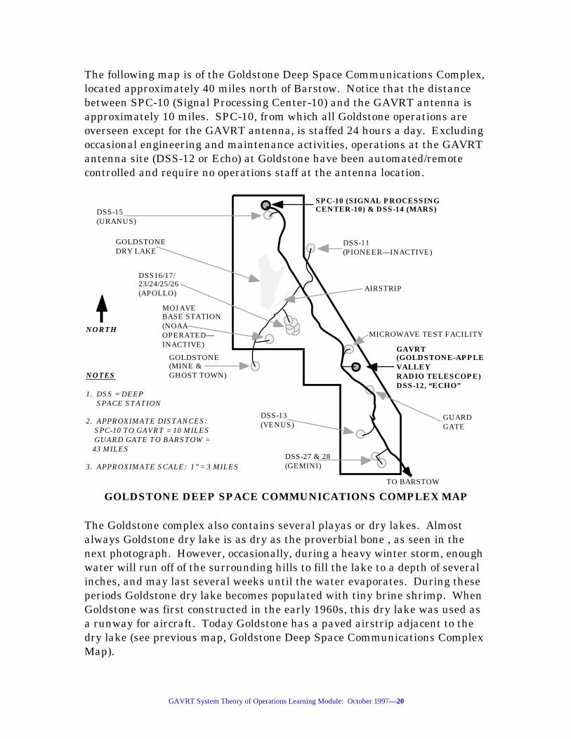
The following map is of the Goldstone Deep Space Communications Complex,located approximately 40 miles north of Barstow. Notice that the distancebetween SPC-10 (Signal Processing Center-10) and the GAVRT antenna isapproximately 10 miles. SPC-10, from which all Goldstone operations areoverseen except for the GAVRT antenna, is staffed 24 hours a day. Excludingoccasional engineering and maintenance activities, operations at the GAVRTantenna site (DSS-12 or Echo) at Goldstone have been automated/remotecontrolled and require no operations staff at the antenna location.
GOLDSTONE DEEP SPACE COMMUNICATIONS COMPLEX MAP
SPC-10 (SIGNAL PROCESSING CENTER-10) & DSS-14 (MARS)
MOJAVEBASE STATION(NOAAOPERATED—INACTIVE)
TO BARSTOW
GUARDGATE
GAVRT (GOLDSTONE-APPLE VALLEYRADIO TELESCOPE)DSS-12, “ECHO”
GOLDSTONE(MINE & GHOST TOWN)
DSS16/17/23/24/25/26(APOLLO)
DSS-11(PIONEER—INACTIVE)
AIRSTRIP
MICROWAVE TEST FACILITY
DSS-15(URANUS)
DSS-13(VENUS)
DSS-27 & 28(GEMINI)
GOLDSTONEDRY LAKE
NORTH
NOTES
1. DSS = DEEP SPACE STATION
2. APPROXIMATE DISTANCES: SPC-10 TO GAVRT = 10 MILES GUARD GATE TO BARSTOW = 43 MILES
3. APPROXIMATE SCALE: 1” = 3 MILES
The Goldstone complex also contains several playas or dry lakes. Almostalways Goldstone dry lake is as dry as the proverbial bone , as seen in thenext photograph. However, occasionally, during a heavy winter storm, enoughwater will run off of the surrounding hills to fill the lake to a depth of severalinches, and may last several weeks until the water evaporates. During theseperiods Goldstone dry lake becomes populated with tiny brine shrimp. WhenGoldstone was first constructed in the early 1960s, this dry lake was used asa runway for aircraft. Today Goldstone has a paved airstrip adjacent to thedry lake (see previous map, Goldstone Deep Space Communications ComplexMap).

GAVRT System Theory of Operations Learning Module: October 1997—21
GOLDSTONE DRY LAKE
QUIZ
1, Driving from the AVSTC to the GAVRT antenna at Goldstonetakes about ____________ minutes. Answer: 90.
2. ...the distance between SPC-10 (Signal Processing Center-10)and the GAVRT antenna is approximately ____________ miles.Answer: 10.
System Overview
The California Institute of Technology’s (Caltech) Jet Propulsion Laboratory(JPL) operates and maintains a world-wide network of deep space trackingstations known as the Deep Space Network (DSN) for the NationalAeronautics and Space Administration (NASA). The DSN is geographicallyarranged into three Deep Space Communications Complexes (DSCC) oftracking stations 120 degrees of latitude apart in Canberra, Australia,Madrid, Spain, and Goldstone, California. Each complex consists of severaldeep space stations (DSS) with steerable antenna aperture diameters from 9to 70 meters. At the Goldstone Deep Space Communications Complex(GDSCC) located in California’s Mojave desert is Deep Space Station-12

GAVRT System Theory of Operations Learning Module: October 1997—22
(DSS-12, also known as the Echo Site). DSS-12 was a steerable, 34 meterdiameter, hour-angle/declination mount, deep space tracking antenna. DSS-12 originally became operational in 1964.
Check out this URL for more detailed information about the DSN (DeepSpace Network):
http://deepspace.jpl.nasa.gov/dsn/index.html
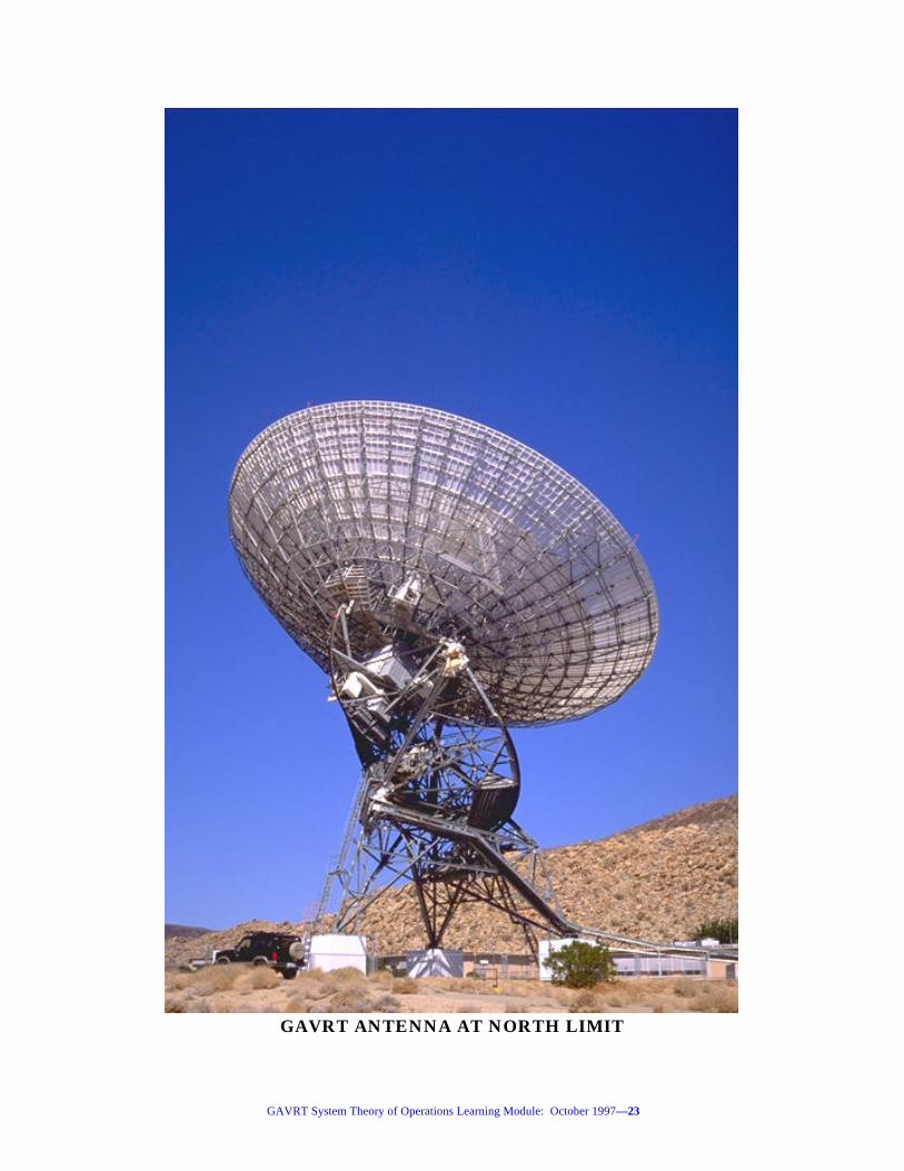
In 1997 DSS-12 was converted into a dedicated radio telescope of the totalpower radiometer type, re-named the Goldstone-Apple Valley Radio Telescope(GAVRT), and operations of the telescope were turned over to the AppleValley Science and Technology Center (AVSTC). The AVSTC makes thisscientific instrument available for use by K-12 schools via the internet. TheAVSTC will oversee day-to-day operations of the GAVRT, and GDSCCpersonnel will maintain the operability of the system.
GAVRT System Theory of Operations Learning Module: October 1997—23
GAVRT ANTENNA AT NORTH LIMIT

GAVRT System Theory of Operations Learning Module: October 1997—24
In conjunction with the California State Polytechnic University--Pomona(Calpoly--Pomona), AVSTC personnel have prepared science curriculaappropriate to the use of the GAVRT by teachers and students in theintegration of radio telescope observations with school curricula. Within thestructure of this curricula are opportunities for students to conceptualize,design, execute, collect the data from, and analyze GAVRT observations viathe internet. Students may perform actual scientific observations whenoperating the telescope in the conduct of their experiments, as well as haveaccess to data collected by other GAVRT experimenters. All GAVRT internetoperations by client schools are conducted under the oversight of GAVRTpersonnel at the AVSTC (Apple Valley Science and Technology Center) inApple Valley.
To introduce the overall functionality of the GAVRT total power radiometer,this overview section is based on the greatly simplified signal/data flowdiagrams (Parts 1 &2) of the GAVRT system. However, all of the majorfunctions and signal/data types of the system are included on these diagrams.

GAVRT System Theory of Operations Learning Module: October 1997—25
GAVRT CONTROL ROOM
SIMPLIFIED GAVRT SYSTEM SIGNAL/DATA FLOW DIAGRAM
PART 1—GAVRT ANTENNA & CONTROL ROOM AT GOLDSTONE
ASTRONOMICALSOURCE RADIO
FREQUENCYSIGNALS
ANTENNAAND RADIO
FREQUENCY FEEDS
LOW NOISE AMPLIFIER
(LNA)
RADIOFREQUENCYELECTRONIC
SIGNALS
AMPLIFIED RADIOFREQUENCY SIGNALS
DOWN-CONVERTER
56 KBPS LINE TO APPLE VALLEY SCIENCE & TECHNOLOGY CENTER
GRS 9-20-96 DRAFT
GAVRT ANTENNA
GAVRT CONTROL ROOM
OBSERVATIONAL DATA (DIGITAL)
POWERMETERSURVEILLANCE
TELEVISION
MONITOR & METEOROLOGICALSIGNALS FROM GAVRT DEVICES
GAVRT SUNSPARC-20
WORKSTATION
CONTROL COMMANDS TO GAVRT DEVICES
OUTSIDE OF THEGAVRT CONTROL ROOM
STILL-FRAMEVIDEO
GAVRTCONTROLCOMMAND BLOCKSFROMAVSTC
ALLDATATYPE
BLOCKSTO AVSTC
INTERMEDIATEFREQUENCYELECTRONIC
SIGNALS(ANALOG)
ELECTRICALPOWER
SOURCES
POWERDISTRIBUTION
TO GAVRT DEVICES
FREQUENCY & TIMING
STANDARDS & REFERENCES
F&T SIGNALS& TIME
TO GAVRT DEVICES
QUIZ
1. In 1997 DSS-12 was converted into a dedicated radio telescope of the________________________________________ type.... Answer: Total powerradiometer.
GAVRT System Theory of Operations Learning Module: October 1997—26
2. All GAVRT internet operations by client schools are conducted underthe oversight of GAVRT personnel at the ____________________________________________________________________________ in Apple Valley.Answer: AVSTC (Apple Valley Science and Technology Center).
At the GAVRT Antenna
The steerable 34 meter diameter GAVRT antenna and RF (radio frequency)feeds collect extremely weak astronomical source RF signals from a verynarrow sector of deep space, and focuses them at the input to the first stageamplifier, the Low Noise Amplifier (LNA). The LNA’s purpose is to increasethe power of the incoming signal as much as possible (100,000-700,000 times)without adding appreciable noise (static). The signal is then translated intoan amplified, proportionally lower, frequency signal called the IntermediateFrequency (IF) by the downconverter.

GAVRT System Theory of Operations Learning Module: October 1997—27
PRIMARYREFLECTOR(PARABOLA)
SECONDARYREFLECTOR
(HYPERBOLA)
CONE,HOUSING
LNA (LOW NOISE AMPLIFIERS &
DOWNCONVERTERS
QUADRAPODASSEMBLY
AVOIDANCELIGHTS
CONEACCESSDOOR
GAVRT ANTENNA REFLECTORS, CONE, AND QUADRAPOD
The amplified IF signal is now strong enough to be sent via coaxial cables tothe Power Meter in GAVRT’s Control Room without being lost in the noise ofthe system.
QUIZ
1. The LNA’s purpose is to increase the power of the incoming signal asmuch as possible (100,000-700,000 times) without adding ___________.Answer: Appreciable noise , or static.
2. The signal is then down-converted into an amplified proportionallylower frequency signal called the ___________________________________.Answer: Intermediate Frequency , or IF.

GAVRT System Theory of Operations Learning Module: October 1997—28
Outside of the GAVRT Control Room
A surveillance TV camera is mounted on top of a mast just outside of thecontrol room. The purpose of this camera is to provide remotely-locatedGAVRT operators a clear view of the GAVRT antenna and its immediateenvironment. This camera sends still-frame video to the GAVRT Sun Sparc-20 Workstation in the control room.
(CAR INCLUDEDTO SHOW SCALE)
SURVEILLANCE TV CAMERA
ANEMOMETER
WINDVANE
WEST-LOOKING VIEW OF THE GAVRT ANTENNA& METEOROLOGICAL SENSORS
Meteorological sensors are also mounted on the surveillance TV camera mastand send meteorological data to the GAVRT Sun Sparc-20 workstation in thecontrol room. The purpose these sensors are twofold, to ensure that out-of-specification conditions (especially high winds) can be remotely monitored,and to allow users to monitor the effects of weather on GAVRT systemperformance (X-band in particular).

GAVRT System Theory of Operations Learning Module: October 1997—29
The Antenna
The GAVRT antenna is located at 116.805° west longitude and 35.300° northlatitude and is mainly made of structural steel, except for the reflectingsurfaces which are made of perforated (to allow water to drain during rainstorms) sheet aluminum. When the antenna was enlarged from 26 to 34meters it was necessary to raise the entire structure 12 feet to provideclearance between the primary reflector and the ground at low elevationangles. This was accomplished by raising and placing the three-leggedstationary supporting structure on 12 foot high concrete raising blocks.

GAVRT System Theory of Operations Learning Module: October 1997—30
WEST-LOOKING VIEW OF THE GAVRT ANTENNA
12 FOOT HIGHCONCRETE
RAISING BLOCKS
PRIMARY REFLECTOR
DECLINATION BULL GEAR
ROTATING DECLINATION CARRIAGE
TO THE CELESTIA
L
SOUTH POLE
TO THE CELESTIA
L NORTH
POLE
POLAR SHAFT ORHOUR ANGLE AXIS
STATIONARY SUPPORTINGSTRUCTURE
TO SOUTH HORIZON TO NORTH HORIZON
DEC SHAFT END OR DECLINATION AXIS
PERIMETERSAFETYFENCE
TO“ZENITH”
TO“NADIR”
HOUR ANGLE CABLE WRAP-UP
The stationary supporting structure supports the hour angle skid (hour angledrive mechanism), the polar (hour angle axis) shaft bearings, the hour angleencoder (translates antenna hour angle angles into digital signals
GAVRT System Theory of Operations Learning Module: October 1997—31
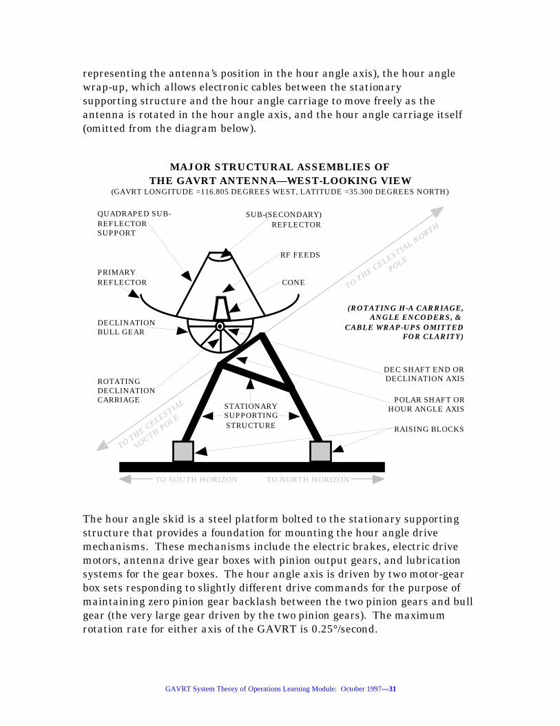
representing the antenna’s position in the hour angle axis), the hour anglewrap-up, which allows electronic cables between the stationarysupporting structure and the hour angle carriage to move freely as theantenna is rotated in the hour angle axis, and the hour angle carriage itself(omitted from the diagram below).
MAJOR STRUCTURAL ASSEMBLIES OFTHE GAVRT ANTENNA—WEST-LOOKING VIEW
(GAVRT LONGITUDE =116.805 DEGREES WEST, LATITUDE =35.300 DEGREES NORTH)
TO THE CELESTIAL
SOUTH POLE
TO THE CELESTIAL N
ORTH
POLE
DEC SHAFT END OR DECLINATION AXIS
QUADRAPED SUB-REFLECTORSUPPORT
DECLINATION BULL GEAR
SUB-(SECONDARY)REFLECTOR
CONE
POLAR SHAFT ORHOUR ANGLE AXIS
PRIMARY REFLECTOR
RAISING BLOCKS
RF FEEDS
STATIONARY SUPPORTING STRUCTURE
(ROTATING H-A CARRIAGE,ANGLE ENCODERS, &
CABLE WRAP-UPS OMITTEDFOR CLARITY)
ROTATING DECLINATION CARRIAGE
TO SOUTH HORIZON TO NORTH HORIZON
The hour angle skid is a steel platform bolted to the stationary supportingstructure that provides a foundation for mounting the hour angle drivemechanisms. These mechanisms include the electric brakes, electric drivemotors, antenna drive gear boxes with pinion output gears, and lubricationsystems for the gear boxes. The hour angle axis is driven by two motor-gearbox sets responding to slightly different drive commands for the purpose ofmaintaining zero pinion gear backlash between the two pinion gears and bullgear (the very large gear driven by the two pinion gears). The maximumrotation rate for either axis of the GAVRT is 0.25°/second.
GAVRT System Theory of Operations Learning Module: October 1997—32
The declination carriage supports the same complement of equipment as thestationary supporting structure for hour angle, except that the declinationcarriage replaces the hour angle carriage, and the primary reflector and allequipment mounted above it, are fastened to the declination carriage. All ofthe equipment on the declination skid works in the same manner as for thehour angle skid. However , many of the declination axis hardware bits andpieces are physically only about two-thirds as large as those used on the hourangle axis. This is acceptable because the declination carriage does not haveto control as much mass.
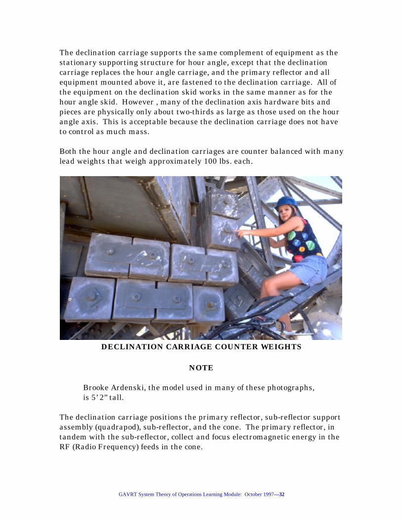
Both the hour angle and declination carriages are counter balanced with manylead weights that weigh approximately 100 lbs. each.
DECLINATION CARRIAGE COUNTER WEIGHTS
NOTE
Brooke Ardenski, the model used in many of these photographs,is 5’ 2” tall.
The declination carriage positions the primary reflector, sub-reflector supportassembly (quadrapod), sub-reflector, and the cone. The primary reflector, intandem with the sub-reflector, collect and focus electromagnetic energy in theRF (Radio Frequency) feeds in the cone.

GAVRT System Theory of Operations Learning Module: October 1997—33
QUIZ
1. The GAVRT antenna is located at 116.805° west longitude and35.300° north latitude and is mainly made of structural __________....Answer: Steel.
2. The hour angle skid is a steel platform bolted to the stationarysupporting structure that provides a foundation for mounting the_____________________ drive mechanisms. Answer: Hour angle.
3. The maximum rotation rate for either axis of the GAVRT is __________/second. Answer: 0.25°.
4. Many of the declination axis hardware bits and pieces are physicallyonly about ________________________ as large as those used on the hourangle axis. Answer: Two-thirds.
5. Both the hour angle and declination carriages are counter balancedwith many lead ________________ .... Answer: Weights.
Inside of the GAVRT Control Room at GDSCC
Data Flow From Goldstone to the AVSTC
The Power Meter measures and digitizes the power level of the signal receivedby the antenna and sends the resulting data to the GAVRT Sun Sparc-20workstation in the control room at Goldstone.

GAVRT System Theory of Operations Learning Module: October 1997—34
GAVRT SUN WORKSTATIONIN THE CONTROL ROOM AT GOLDSTONE
The GAVRT Sun Sparc-20 workstation organizes the power meter’smeasurements, along with surveillance television still-frame video, monitor(GAVRT configuration and parameter data), and meteorological datagenerated by GAVRT devices, and sends them across a 56 kbps full duplexcommunications line to the AVSTC in Apple Valley.
Data Flow From The AVSTC to Goldstone
The GAVRT control command data blocks are sent from the AVSTC SunSparc-20 workstation in Apple Valley to the GAVRT Sun Sparc-20workstation at Goldstone. This data is processed by the GAVRT Sun Sparc-20 workstation, which commands GAVRT devices to various configurations
GAVRT System Theory of Operations Learning Module: October 1997—35
including antenna pointing control, S and/or X-band reception, and powermeasurement and calibration.
Frequency and timing signals and time are provided to GAVRT devices byGoldstone’s Deep Space Network Frequency and Timing Subsystem (FTS).
Either the commercial power grid, or emergency diesel motor-generator sets,provide electrical power for distribution to all GAVRT devices at Goldstone.
GAVRT control command blocks sent to the GAVRT Workstation arereceived from the AVSTC Workstation via the 56 kbps line, verified, anddistributed to the appropriate GAVRT device(s) for execution.
QUIZ
1. The Power Meter _________________________________________ thepower level of the signal received by the antenna.... Answer: Measures anddigitizes.
2. The GAVRT Control _________________________ Blocks arrive at theGAVRT Sun Sparc-20 Workstation from the AVSTC Sun Sparc-20Workstation in Apple Valley. Answer: Command.
At the AVSTC
The AVSTC is staffed with AVUSD operators trained in the operation of theGAVRT system, the Sun Sparc-20 workstation, associated software, and theoperation of downstream schools’ personal computers and associatedsoftware.

GAVRT System Theory of Operations Learning Module: October 1997—36
THE APPLE VALLEY SICENCE AND TECHNOLOGY CENTER
All data type blocks from Goldstone arrive at the AVSTC Sun Sparc-20workstation via a 56 kbps full duplex communications line. The AVSTCworkstation is remotely logged-onto by the GAVRT workstation in AppleValley. All data type blocks from Goldstone are processed by the GAVRTWorkstation, which in response to student inputs, forwards requested datatypes to the end users’ PCs via the internet, and displays GAVRTsurveillance TV images on the AVSTC Sun Sparc-20 workstation.

GAVRT System Theory of Operations Learning Module: October 1997—37
SIMPLIFIED GAVRT SYSTEM SIGNAL/DATA FLOW DIAGRAMPART 2—SYSTEM ELEMENTS AT
APPLE VALLEY SCIENCE AND TECHNOLOGY CENTER & END USERS’ SCHOOLS
56 KBPS LINE FROM GOLDSTONE-APPLE VALLEY RADIO TELESCOPE
ALLDATATYPE
BLOCKSFROM
GAVRT
GAVRTCONTROLCOMMAND BLOCKS
TO GAVRT
APPLE VALLEY SCIENCE & TECHNOLOGY CENTER
END USERS’ SCHOOLS
ALLDATATYPE
BLOCKSTO END USERS’
SCHOOLS
GRS 9-20-96 DRAFT
GAVRTCONTROLCOMMAND BLOCKS
TO AVSTC
ALLDATATYPE
BLOCKSFROM AVSTC
GAVRTCONTROLCOMMAND BLOCKS
FROM END USERS’
SCHOOLS
APPLE VALLEY SCIENCE & TECHNOLOGY CENTER
AVSTC SUNSPARC-20
WORKSTATION
INTERNET
END USERS’PCs
COMMERCIALPOWER
GRID
POWERDISTRIBUTION
TO AVSTC EQUIPMENT
COMMERCIALPOWER
GRID
POWERDISTRIBUTION
TO END USERS’EQUIPMENT
QUIZ
1. All data type blocks from Goldstone arrive at the AVSTC Sun Sparc-20Workstation via a __________________ full duplex communications line.Answer: 56 kbps.

GAVRT System Theory of Operations Learning Module: October 1997—38
At the End Users Schools
End Users’ PCs receive and may record all data type blocks (exceptsurveillance TV) from the AVSTC for non-realtime data analysis dataanalysis. As of the October 1997, the bandwidth constraints between theAVSTC and client schools prohibit forwarding of surveillance TV images tothe client schools.
End Users’ PCs have applications software installed to support thedownloading, recording, and non-realtime analysis of GAVRT observationaldata.
The GAVRT control command blocks to AVSTC are originated at the endusers’ PCs using provided applications software and sent to the AVSTCworkstation via the internet.
All end users school’s devices are powered from the commercial power grid.
So, the end user’s PCs are logged onto the GAVRT workstation in AppleValley, which is logged onto the GAVRT workstation at Goldstone, allowingusers at the remotely-located client schools to operate the GAVRT system.
QUIZ
1. ...bandwidth constraints between the AVSTC and client schoolsprohibit forwarding of ______________________________ images to theclient schools. Answer: Surveillance TV.
2. End Users’ PCs have applications software installed to support thedownloading, recording, and non-realtime analysis of GAVRT_____________________ data. Answer: Observational.

GAVRT System Theory of Operations Learning Module: October 1997—39
THEORY OF OPERATION—FUNCTIONAL BLOCK DIAGRAMS
Learning Objectives for this Section
Completion of this section will enable learners to:
• Describe the function of the sub-reflector
• Characterize the signals passed from the sub-reflector to the dichroicplate
• Describe the function of the RF mirror
• Describe the function of the S-band feed horn
• Describe the function of the polarizer
• Describe the function of the microwave switch
• Describe the function of the coupler
• Describe the function of the LNA
• Characterize the signals passed from the LNA to the S & X-banddownconverter
• Describe the function of the S & X-band downconverter
• Characterize the signals passed from the S & X-band downconverter tothe distribution amplifier
• Describe the function of the power meter
• Characterize the data passed from the power meter across the IEEE-488 bus.
• Characterize the signal passed from the distribution amplifier throughthe S/X-band selector switch to the spectrum analyzer
• Describe the function of the spectrum analyzer

GAVRT System Theory of Operations Learning Module: October 1997—40
• Characterize the data passed from the spectrum analyzer across theIEEE-488 bus
• Describe the function of the serial controller associated with thedistribution amplifier
• Characterize the data passed between the serial controller and theIEEE-488 bus
• Describe the function of the X-band rain blower
• Characterize the signals passed between the X-band rain blower andthe relay box
• Describe the function of the relay box
• Characterize the data passed between the relay box and its associatedserial controller
• Describe the function of the ambient load
• Characterize the signals passed from the ambient load to the quartzthermometer
• Describe the function of the quartz thermometer
• Characterize the data passed between the quartz thermometer and thetemperature display
• Describe the function of the temperature display
• Characterize the data passed between the temperature display and theIEEE-488 bus
• Describe the function of the S & X-band noise diodes
• Characterize the data passed from the S & X-band noise diodes to theserial controller
• Describe the function of the sub-reflector controller
• Characterize the data passed between the sub-reflector controller andthe relay box

GAVRT System Theory of Operations Learning Module: October 1997—41
• Describe the function of the weather station
• Characterize the data passed from the weather station to its associateserial controller
• Describe the function of the surveillance television
• Characterize the signals passed between the surveillance televisionand station controller Wizard
• Describe the function of the time code translator
• Characterize the data passed between the time code translator andstation controller Wizard
• Describe the function of the antenna control subsystem
• Characterize the data passed between the antenna control subsystemand station controller Wizard
• Describe the function of the integrity fence interlock
• Characterize the signal passed from the integrity fence interlock andstation controller Wizard
• Characterize the signals passed from station controller Wizard to thefloodlights
• Characterize the data passed between station controller Wizard andworkstation Oz
• Describe the bandwidth of the communications line between stationcontroller Wizard and workstation Oz
• Describe the function of workstation Oz
• Identify the communications medium between workstation Oz andPC/Mac personal computer Dorothy
• Characterize the data passed between workstation Oz and PC/Macpersonal computer Dorothy

GAVRT System Theory of Operations Learning Module: October 1997—42
• Describe the overall purpose of the universal time function
• Describe the overall purpose of the GAVRT monitor and controlfunction
Introduction
In this section the GAVRT system theory of operation will be discussed downto the functional block diagram level of detail, in terms of describing theinputs to, functions of, and the outputs of each functional block. If you areunfamiliar with the astronomical terms used in this section, such as rightascension, declination, hour angel, celestial poles, etc., please complete the“Basics of Radio Astronomy” learning module before proceeding. The “Basicsof Radio Astronomy” learning module may be downloaded without chargefrom URL:
http://www.jpl.nasa.gov/radioastronomy/
Several highlighted versions of the following functional block diagram of theGAVRT System will be used to support the presentation of this section.
GAVRT Functional Block Diagram
The following drawing represents all of the major functions of the GAVRTSystem, including calibration configurations. The geographical boundaries ofthe domains within which the system elements reside are shown as dottedlines, and the domains are labeled in underlined italics. Each box represents afunction of the GAVRT system. Several radio frequency elements, the sub-reflector, dichroic plate, etc., are shown as pictographs. When the signal/dataarrows are single-headed, they are showing the direction of the signal/dataflow. When they are double-headed, they indicate that there is data flow inboth directions. When the interconnecting logical wires carry electricity thatis RF (radio frequency) and analog in nature, they are referred to as signallines. When the interconnecting logical wires carry electricity that is binaryand digital in nature, they are referred to as data lines. Annotations to thediagrams are presented in italics.
The interconnecting lines and arrows represent logical interfaces that oftenconsist of many wires that have been simplified into single wires here forclarity. Also omitted are many circuit elements that perform calculations on,amplify, and attenuate signal and/or data flow. A discussion of these

GAVRT System Theory of Operations Learning Module: October 1997—43
elements is not required to attain a functional understanding of the GAVRTSystem.
The microwave switch symbols, shown here as a square, enclosing a circle,enclosing two quarter-circles, are two-position switches that pass RF (RadioFrequency) signals as indicated by the quarter-circles, or by rotating thequarter-circles 90 degrees clockwise or counter-clockwise to configure thealternate microwave pathway.

GAVRT System Theory of Operations Learning Module: October 1997—44
PC/MACPERSONAL COMPUTERDOROTHY
SUB-REFLECTOR
CONTROLLER(SRC)
RELAYBOX
LEGENDDomain Boundaries
Annota-tions
Signals and/ordata
=
= Italicized
=
Control Room
Equipment
Antenna Mounted Equipment Client Schools
LAN
ROUTER
IEEE-488 BUS
GDSCC HYDROGEN MASER REFERENCE
CONTROL TOFLOODLIGHTS
TEMPER-ATURE
DISPLAY
56 KBPSCOMMLINE
STATIONCONTROLLER
WIZARD
SPECTRUM ANALYZER
VIDEO &CONTROL
SERIALCON-
TROLLER
TIMECODE
TRANSLATOR
SURVEIL-LANCE TVCAMERA
POWER METER
S/X BAND SELECTOR
SWITCHDISTRI-BUTION
AMPLIFIER POWER METER
SERIALCON-
TROLLER
FROM WEATHER STATION
DISTRI-BUTION
AMPLIFIER
S-BAND IF X-BAND IF
S & X-BANDDOWN
CONVERTER
COUPLER
AMBIENT LOAD
S-BAND (RF)
POLARIZER
QUARTZTHER-
MOMETER
X-BAND(RF)
POLARIZER
COUPLER
X--BANDRAIN BLOWER
X-BAND FEED HORN
SUB-REFLECTOR
DICHROICPLATE
RF MIRROR
SRC “RESET”COMMANDS
ROUTER
LAN
INTERNET
WORKSTATION
OZ
INTEGRITY FENCE INTERLOCK
AVSTC
S & X-BAND RF SIGNALS
GAVRT FUNCTIONAL BLOCK DIAGRAMGRS: 8-28-97
S-BAND FEED HORN
S & X-BANDNOISE
DIODESLOW-NOISEAMPLI-
FIER
LOW-NOISEAMPLI-FIER
I.F. TODSS-13
SERIALCON-
TROLLER
SERIALCON-
TROLLER
ANTENNACONTROL
SUBSYSTEM
S X

GAVRT System Theory of Operations Learning Module: October 1997—45
Universal Time Functional Block Diagram
NOTE
Take a moment to review the following diagram, Universal TimeFunctional Block Diagram. Notice that only the elements of theoverall block diagram that are under discussion arehighlighted. This approach will be used to focus attention inturn on each functional area of the diagram until the full set ofGAVRT system functions have been presented.
As in all astronomical activities, accurate and precise time is required. TheDSN’s (Deep Space Network’s) Frequency and Timing System (FTS) atGoldstone provides extremely accurate and precise timing and frequencysignals and data to all of the antenna sites at Goldstone. The hydrogenmasers used in the DSN (Deep Space Network) are configured to operate inthe oscillation mode. In this mode hydrogen masers are extremely stableoscillators that provide the GAVRT frequency and timing equipment a verystable reference frequency that is both accurate and precise.
The following diagram shows how data arriving from the GAVRT system atthe “Dorothy” (client school) personal computers is time-tagged.

GAVRT System Theory of Operations Learning Module: October 1997—46
PC/MACPERSONAL COMPUTERDOROTHY
SUB-REFLECTOR
CONTROLLER(SRC)
RELAYBOX
LEGENDDomain Boundaries
Annota-tions
Signals and/ordata
=
= Italicized
=
Control Room
Equipment
Antenna Mounted Equipment Client Schools
LAN
ROUTER
GDSCC HYDROGEN MASER REFERENCE
CONTROL TOFLOODLIGHTS
TEMPER-ATURE
DISPLAY
56 KBPSCOMMLINE
STATIONCONTROLLER
WIZARD
SPECTRUM ANALYZER
VIDEO &CONTROL
SERIALCON-
TROLLER
TIMECODE
TRANSLATOR
SURVEIL-LANCE TVCAMERA
POWER METER
DISTRI-BUTION
AMPLIFIER POWER METER
SERIALCON-
TROLLER
FROM WEATHER STATION
DISTRI-BUTION
AMPLIFIER
S & X-BANDDOWN
CONVERTER
COUPLER
AMBIENT LOAD
POLARIZER
QUARTZTHER-
MOMETER
POLARIZER
COUPLER
X--BANDRAIN BLOWER
X-BAND FEED HORN
SUB-REFLECTOR
DICHROICPLATE
RF MIRROR
SRC “RESET”COMMANDS
ROUTER
LAN
INTERNET
WORKSTATION
OZ
INTEGRITY FENCE INTERLOCK
AVSTC
UNIVERSAL TIME FUNCTIONAL BLOCK DIAGRAMGRS: 8-28-97
S-BAND FEED HORN
S & X-BANDNOISE
DIODESLOW-NOISEAMPLI-
FIER
LOW-NOISEAMPLI-FIER
I.F. TODSS-13
SERIALCON-
TROLLER
SERIALCON-
TROLLER
ANTENNACONTROL
SUBSYSTEM
IEEE-488 BUS
S/X BAND SELECTOR
SWITCH
S-BAND IF X-BAND IF
S-BAND (RF) X-BAND(RF)
S & X-BAND RF SIGNALS
S X

GAVRT System Theory of Operations Learning Module: October 1997—47
The Goldstone hydrogen maser reference signal is provided to the time codetranslator in the control room at the GAVRT site to update the time codetranslator’s clock. The time code translator delivers very accurate and precisetime to station controller “Wizard”, which tags (attaches) time to each datawrapper (data packet) sent out from “Wizard”.
Various kinds of data, as we will see on the following diagrams, are sent fromWizard, across a LAN (Local Area Network) to a router (a device that “routes”data packets to their correct destinations), and onto a commercial 56 kbpsComm (Communications) line.
The other end of this line is connected through a router, across a LAN (LocalArea Network) to workstation “Oz” at the AVSTC (Apple Valley Science andTechnology Center) in Apple Valley, California.
Using FTP (File Transfer Protocol) techniques, workstation “Oz” sends time-tagged data wrappers across the internet to PC/Mac personal computer“Dorothy” at the client school. The PC/Mac personal computer “Dorothy”displays accurately and precisely time-tagged GAVRT system data.
The GAVRT system does not adjust the clock in the PC/Mac personalcomputer “Dorothy”. To learn how to accurately set the clock on “Dorothy”computers, visit the United States Navel Observatory at URL:
http://tycho.usno.navy.mil/what.html
or at URL:
http://tycho.usno.navy.mil/time.html
QUIZ
1. ...hydrogen masers are extremely stable oscillators that provide theGAVRT frequency and timing equipment a very stable referencefrequency that is both ____________________________________. Answer:Accurate and precise.
2. ... Station controller “Wizard”, which tags (attaches) ______________ toeach data wrapper (data packet) sent out from “Wizard”. Answer: Time.
3. Using ___________________________________ techniques, Workstation“Oz” sends time-tagged data wrappers across the internet to PC/Macpersonal computer “Dorothy”.... Answer: FTP, or File Transfer Protocol.

GAVRT System Theory of Operations Learning Module: October 1997—48
Monitor and Control Functional Block Diagram
The overall GAVRT monitor and control function monitors the configurationand performance parameters of the GAVRT system and delivers this data tothe PC/Mac personal computer “Dorothy” at the client school. This functionalso develops system commands (instructions to the GAVRT system) anddelivers them to the appropriate system elements at the AVSTC (Apple-Valley Science and Technology Center), and at the GAVRT site at Goldstonefor execution.
Observational data (from a astronomical source) is not delivered by theGAVRT Monitor & Control function, but will be addressed on the S-Band andX-Band Observational Functional Block diagrams presented later in thissection.

GAVRT System Theory of Operations Learning Module: October 1997—49
PC/MACPERSONAL COMPUTERDOROTHY
SUB-REFLECTOR
CONTROLLER(SRC)
RELAYBOX
LEGENDDomain Boundaries
Annota-tions
Signals and/ordata
=
= Italicized
=
Control Room
Equipment
Antenna Mounted Equipment Client Schools
LAN
ROUTER
GDSCC HYDROGEN MASER REFERENCE
CONTROL TOFLOODLIGHTS
TEMPER-ATURE
DISPLAY
56 KBPSCOMMLINE
STATIONCONTROLLER
WIZARD
SPECTRUM ANALYZER
VIDEO &CONTROL
SERIALCON-
TROLLER
TIMECODE
TRANSLATOR
SURVEIL-LANCE TVCAMERA
POWER METER
DISTRI-BUTION
AMPLIFIER POWER METER
SERIALCON-
TROLLER
FROM WEATHER STATION
DISTRI-BUTION
AMPLIFIER
S & X-BANDDOWN
CONVERTER
COUPLER
AMBIENT LOAD
POLARIZER
QUARTZTHER-
MOMETER
POLARIZER
COUPLER
X--BANDRAIN BLOWER
X-BAND FEED HORN
SUB-REFLECTOR
DICHROICPLATE
RF MIRROR
SRC “RESET”COMMANDS
ROUTER
LAN
INTERNET
WORKSTATION
OZ
INTEGRITY FENCE INTERLOCK
AVSTC
MONITOR & CONTROL FUNCTIONAL BLOCK DIAGRAMGRS: 8-28-97
S-BAND FEED HORN
S & X-BANDNOISE
DIODESLOW-NOISEAMPLI-
FIER
LOW-NOISEAMPLI-FIER
I.F. TODSS-13
SERIALCON-
TROLLER
SERIALCON-
TROLLER
ANTENNACONTROL
SUBSYSTEM
IEEE-488 BUS
S/X BAND SELECTOR
SWITCH
S-BAND IF X-BAND IF
S-BAND (RF) X-BAND(RF)
S & X-BAND RF SIGNALS
S X

GAVRT System Theory of Operations Learning Module: October 1997—50
The GAVRT Monitor & Control function measures the configuration andperformance of various GAVRT system elements at the GAVRT site atGoldstone, and accesses specified data at the “Oz” computer at the AVSTC(Apple Valley Science and Technology Center). Also, commands prepared atthe “Dorothy” personal computer at the client school, are forwarded through“Oz”, and on to “Wizard” at Goldstone for execution.
Regarding the monitor function, the S and X-band polarizers send polarizerangle and mode data through the relay box, serial controller, IEEE-488 bus, tothe station controller “Wizard”, in the control room at Goldstone.

GAVRT System Theory of Operations Learning Module: October 1997—51
POLARIZERBULL GEAR POLARIZER
GEAR BOX
POLARIZERDRIVE
MOTOR
S-BAND POLARIZER ASSEMBLY,INSIDE THE RF CONE ON THE ANTENNA
Sub-reflector, and the S and X-band microwave switch positional data followthe same path to “Wizard”. Both S and X-band power meters, spectrumanalyzer, temperature display (system temperature), and “from weatherstation” meteorological data are sent directly across the IEEE-488 bus to“Wizard”. The Antenna Control Subsystem provides GAVRT antenna angledata, and the surveillance TV camera provides still frame video directly to“Wizard”.
The following photograph depicts GAVRT antenna sub-reflector.

GAVRT System Theory of Operations Learning Module: October 1997—52
GAVRT ANTENNA SUB-REFLECTOR ASSEMBLY
PRIMARYREFLECTOR
CONE
S-BANDFEED
X-BANDFEED
SUB-REFLECTOR
SUB-REFLECTORSUPPORT
ASSEMBLY(QUADRAPOD)
DICHROICPLATE
RF MIRROR
BROOKEARDENSKI

GAVRT System Theory of Operations Learning Module: October 1997—53
The GAVRT antenna integrity fence interlock system interrupts the drivesignal to the antenna drive system if the perimeter fence looses its integrity,stopping all antenna movement immediately. In a like manner, the systemalso includes interlocked gate-covers for each of the two access ladders on theantenna. Opening either of these two access gates also stops all antennamovement immediately in the same manner as employed by the fence.
This system was installed to prevent vehicles and/or equipment from beingmoved into the area under the antenna without interrupting antennamovement. During heavy maintenance or overhauls the fence segments can beremoved to provide access for heavy equipment.

GAVRT System Theory of Operations Learning Module: October 1997—54
GAVRT ANTENNA PERIMETER INTEGRITY FENCE
FENCE POST SOCKET
FENCE SEGMENTDISCONNECT PLUG
REMOVABLE FENCE POST
GAVRT System Theory of Operations Learning Module: October 1997—55
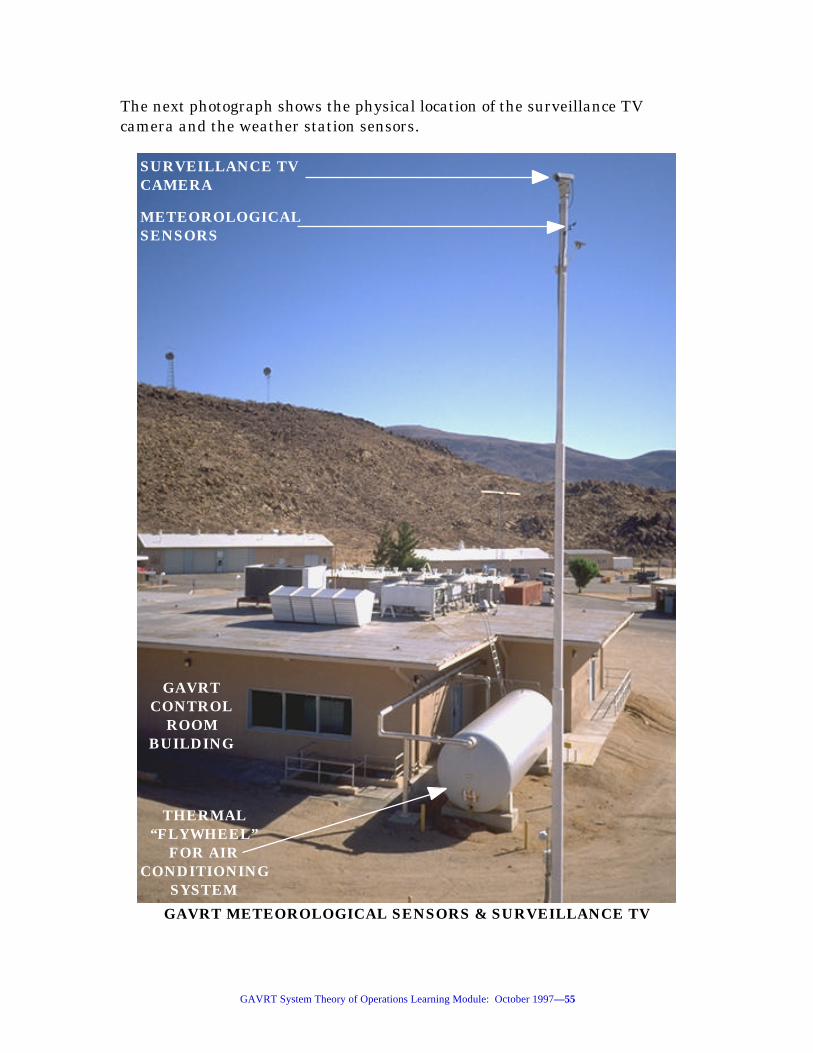
The next photograph shows the physical location of the surveillance TVcamera and the weather station sensors.
GAVRT METEOROLOGICAL SENSORS & SURVEILLANCE TV
METEOROLOGICALSENSORS
SURVEILLANCE TVCAMERA
GAVRTCONTROL
ROOMBUILDING
THERMAL“FLYWHEEL”
FOR AIR CONDITIONING
SYSTEM

GAVRT System Theory of Operations Learning Module: October 1997—56
Commands that tell the GAVRT what to do are originated at the PC/Macpersonal computer “Dorothy”, are forwarded across the internet toworkstation “Oz” at the AVSTC and on across a LAN, through a router, andacross a 56 kbps communications line to the GAVRT control room atGoldstone.
Command data arriving at the GAVRT control room passes through a routerand LAN, and through station controller wizard, directs it to the appropriateequipment, like the antenna floodlights shown on the next page.

GAVRT System Theory of Operations Learning Module: October 1997—57
GAVRT ANTENNA FLOODLIGHTS & CONTROL ROOM BUILDING
FLOODLIGHTS
FLOODLIGHTSERVICE
PANEL
GAVRTCONTROL
ROOMBUILDING
HYDRO-MECHANICAL
BUILDING
CONTROL ROOM/ HYDRO-MECHANICAL
SERVICE TUNNEL

GAVRT System Theory of Operations Learning Module: October 1997—58
Other GAVRT equipment controlled by station controller wizard includes:surveillance TV camera, Antenna Control Subsystem, S-X selector switch,spectrum analyzer, power meters, and S & X-band noise diodes.
QUIZ
1. The overall GAVRT monitor and control function monitors the_____________________________________ parameters of the GAVRTsystem and delivers this data to the PC/Mac personal computer“Dorothy” at the client school. Answer: Configuration and performance.
2. ... commands prepared at the “Dorothy” personal computer at the clientschool, are forwarded through “Oz”, and on to “Wizard” at Goldstone for____________________ . Answer: Execution.
3. The integrity fence was installed to prevent vehicles and/or equipmentfrom being moved into the area under the antenna without interruptingantenna _____________________. Answer: Movement.
S-Band Calibration Functional Block Diagram
To establish and maintain accurate and precise calibration of the GAVRTsystem, it must be routinely calibrated. This task is performed by trainedpersonnel at the AVSTC (Apple Valley Science & Technology Center).However, system users should have a general understanding of the calibrationfunctional block diagrams to appreciate how the system is calibrated for theprecise and accurate measurement of astronomical signals.
When acquiring the very weak electromagnetic radiation from astronomicalsources the amount of noise (random electron movement) created by each RF(Radio Frequency) system element, by man-made noise, and by thebackground noise of free space, makes it difficult to distinguish between thesignal and noise components of the signal arriving at the LNA (Low NoiseAmplifier).
NOTE
Do not confuse the terms audio noise and RF noise.
Audio Noise refers to unorganized audio frequency (0-20 khz)sound waves propagated through a medium, such as air.

GAVRT System Theory of Operations Learning Module: October 1997—59
RF Noise refers to unorganized (random) radio frequency waves.
Unlike sound waves, electromagnetic waves do not require amedium for propagation, and can be propagated through space.Noise is contributed by the random electron movements of eachsystem element, the atmosphere, and the background noise ofdeep space.

GAVRT System Theory of Operations Learning Module: October 1997—60
PC/MACPERSONAL COMPUTERDOROTHY
SUB-REFLECTOR
CONTROLLER(SRC)
RELAYBOX
LEGENDDomain Boundaries
Annota-tions
Signals and/ordata
=
= Italicized
=
Control Room
Equipment
Antenna Mounted Equipment Client Schools
LAN
ROUTER
GDSCC HYDROGEN MASER REFERENCE
CONTROL TOFLOODLIGHTS
TEMPER-ATURE
DISPLAY
56 KBPSCOMMLINE
STATIONCONTROLLER
WIZARD
SPECTRUM ANALYZER
VIDEO &CONTROL
SERIALCON-
TROLLER
TIMECODE
TRANSLATOR
SURVEIL-LANCE TVCAMERA
POWER METER
DISTRI-BUTION
AMPLIFIER POWER METER
SERIALCON-
TROLLER
FROM WEATHER STATION
DISTRI-BUTION
AMPLIFIER
S & X-BANDDOWN
CONVERTER
COUPLER
AMBIENT LOAD
POLARIZER
QUARTZTHER-
MOMETER
POLARIZER
COUPLER
X--BANDRAIN BLOWER
X-BAND FEED HORN
SUB-REFLECTOR
DICHROICPLATE
RF MIRROR
SRC “RESET”COMMANDS
ROUTER
LAN
INTERNET
WORKSTATION
OZ
INTEGRITY FENCE INTERLOCK
AVSTC
S-BAND CALIBRATION FUNCTIONAL BLOCK DIAGRAMGRS: 8-28-97
S-BAND FEED HORN
S & X-BANDNOISE
DIODESLOW-NOISEAMPLI-
FIER
LOW-NOISEAMPLI-FIER
I.F. TODSS-13
SERIALCON-
TROLLER
SERIALCON-
TROLLER
ANTENNACONTROL
SUBSYSTEM
IEEE-488 BUS
S/X BAND SELECTOR
SWITCH
S-BAND IF X-BAND IF
S-BAND (RF) X-BAND(RF)
S & X-BAND RF SIGNALS
S X

GAVRT System Theory of Operations Learning Module: October 1997—61
At the beginning of the calibration procedure, the S & X-band noise diodes arecommanded “Off” by the station controller wizard. Observe on the abovediagram that the S & X-band selector switch is positioned to route one of theoutputs of the S-band distribution amplifier to the spectrum analyzer. Also,the microwave switch mounted on the antenna is positioned to connect theambient load to the coupler. This configuration removes the deep spacebackground noise, RFI (radio frequency interference--man-made noise), andatmospheric noise from the system calibration measurements.
NOTE
Some of the longer signal/data flow descriptions in this moduleare presented in outline form for clarity.
The station controller wizard sends commands:
1. Across the IEEE-488 bus,
2. Through a serial controller,
3. To the S & X-band noise diodes to turn them “On” or “Off”.
NOTES
When the diodes are “Off”, the power meter is measuring thequiescent system noise.
When the diodes are “On” the power meter is also measuring thesystem noise level, but with a calibrated quantity of injectednoise added to the signal path by the ambient load.
The noise created by the X-band ambient load is:
1. The signal is then passed through the coupler (a device that merges twoRF signals into a single composite signal), where the output of the S &X-band noise diodes are added to the noise signal when the diodes are“On”,
2. On to the S-band LNA (Low Noise Amplifier), a device specificallyengineered to amplify the signal while adding minimal noise to theoverall system noise),

GAVRT System Theory of Operations Learning Module: October 1997—62
3. Through the S & X-band down-converter (a device that converts the RF[Radio Frequency] signals into a proportional IF [IntermediateFrequency--a few megahertz in this case] signal),
4. Through the S-band distribution amplifier that maintains the IF signallevel and sends the signal:
a. Through the S-X-band selector switch,
1. Through the spectrum analyzer , which is used to displayRF spectral information used to monitor the presence ofman-made RF interference during the calibrations,
2. Across the IEEE-488 bus,
3. To station controller wizard, for recording, display andanalysis.
b. And through the power meter, a device that measures the IFsignal and converts [A-D, analog to digital] it into equivalentdata that is forwarded:
1. Across the IEEE-488 bus,
2. To station controller wizard, for recording, display andanalysis.
Meteorological data is important to noise calculations because variations inthe water vapor content of the atmosphere dramatically changes themeasured system temperature (Ts), especially at X-band. Signals from theweather station are;
1. Passed through the serial controller,
2. Across the IEEE-488 bus,
3. To the station controller “Wizard” for recording, forwarding, analysis,and display.
The temperature of the ambient load is measured by the quartzthermometer, a very precise electronic thermometer, which sends a signal to:

GAVRT System Theory of Operations Learning Module: October 1997—63
1. The temperature display, which displays and sends the derivedtemperature data to,
2. The station controller “Wizard” for processing and display.
During the calibration procedure the S & X-band noise diodes are switched“On” and “Off”, while “Wizard” analyzes the changes in power (strength) of thesignal measured by the power meter, and factors in the temperature of theambient load, to calculate Ts (System Temperature). Weather station andspectrum analyzer data are used by AVSTC operators to verify that non-astronomical conditions are not causing false readings during the calibrationprocedure.
QUIZ
1. RF Noise refers to unorganized (random)_________________________________ waves. Answer: Radio frequency.
2. ...electromagnetic waves do not require a _______________ forpropagation.... Answer: Medium.
X-Band Calibration Functional Block Diagram
In principal calibration of the X-band portions of the GAVRT system are thesame as for the S-band portions. However, keep in mind that atmosphericwater vapor content (humidity) has much more effect on X-band performancethan it does on S-band performance.

GAVRT System Theory of Operations Learning Module: October 1997—64
PC/MACPERSONAL COMPUTERDOROTHY
SUB-REFLECTOR
CONTROLLER(SRC)
RELAYBOX
LEGENDDomain Boundaries
Annota-tions
Signals and/ordata
=
= Italicized
=
Control Room
Equipment
Antenna Mounted Equipment Client Schools
LAN
ROUTER
GDSCC HYDROGEN MASER REFERENCE
CONTROL TOFLOODLIGHTS
TEMPER-ATURE
DISPLAY
56 KBPSCOMMLINE
STATIONCONTROLLER
WIZARD
SPECTRUM ANALYZER
VIDEO &CONTROL
SERIALCON-
TROLLER
TIMECODE
TRANSLATOR
SURVEIL-LANCE TVCAMERA
POWER METER
DISTRI-BUTION
AMPLIFIER POWER METER
SERIALCON-
TROLLER
FROM WEATHER STATION
DISTRI-BUTION
AMPLIFIER
S & X-BANDDOWN
CONVERTER
COUPLER
AMBIENT LOAD
POLARIZER
QUARTZTHER-
MOMETER
POLARIZER
COUPLER
X--BANDRAIN BLOWER
X-BAND FEED HORN
SUB-REFLECTOR
DICHROICPLATE
RF MIRROR
SRC “RESET”COMMANDS
ROUTER
LAN
INTERNET
WORKSTATION
OZ
INTEGRITY FENCE INTERLOCK
AVSTCS-BAND FEED HORN
S & X-BANDNOISE
DIODESLOW-NOISEAMPLI-
FIER
LOW-NOISEAMPLI-FIER
I.F. TODSS-13
SERIALCON-
TROLLER
SERIALCON-
TROLLER
ANTENNACONTROL
SUBSYSTEM
X-BAND CALIBRATION FUNCTIONAL BLOCK DIAGRAMGRS: 8-28-97
IEEE-488 BUS
S/X BAND SELECTOR
SWITCH
S-BAND IF X-BAND IF
S-BAND (RF) X-BAND(RF)
S & X-BAND RF SIGNALS
S X

GAVRT System Theory of Operations Learning Module: October 1997—65
At the beginning of the calibration procedure, the S & X-band noise diodes arecommanded “Off” by the station controller “Wizard”. Observe on the abovediagram that the S & X-band selector switch is positioned to route one outputof the X-band distribution amplifier to the spectrum analyzer. Also, themicrowave switch mounted on the antenna is positioned to connect theambient load to the coupler. This configuration removes the deep spacebackground noise, RFI (radio frequency interference--man-made noise), andatmospheric noise from the calibration measurements.
The station controller “Wizard” sends commands:
1. Across the IEEE-488 bus,
2. Through a serial controller,
3. To the S & X-band noise diodes to turn them “On” and “Off”.
The noise created by the X-band ambient load is:
1. Passed through the coupler (a device that merges two RF signals into asingle composite signal), where the output of the S & X-band noisediodes are added to the noise signal when the diodes are “On”,
2. To the X-band LNA (Low Noise Amplifier), a device specificallyengineered to amplify the signal while adding minimal noise to theoverall system noise),
3. Through the S & X-band down-converter, a device that converts the RF(Radio Frequency) signals into a proportional IF (IntermediateFrequency)--a few megahertz in this case] signal,
4. Through the X-band distribution amplifier that maintains the IF signallevel and sends the signal:
a. Through the S-X-band selector switch,
1. Through the spectrum analyzer (used to display RFspectral information used to monitor for the presence ofman-made RF interference during the calibrations),
2. Across the IEEE-488 bus,

GAVRT System Theory of Operations Learning Module: October 1997—66
3. To station controller “Wizard”, for recording, forwarding,display and analysis.
b. And through the power meter, a device that measures the IFsignal and converts (A-D, analog to digital) it into equivalentdata that is forwarded:
1. Across the IEEE-488 bus
2. To station controller “Wizard”, for recording, display andanalysis.
Meteorological data is important to noise calculations because variations inthe water vapor content of atmosphere dramatically change the measuredsystem temperature (Ts), especially at X-band. Signals from the weatherstation are;
1. Passed through the serial controller,
2. Across the IEEE-488 bus,
3. To the station controller wizard for recording, forwarding, analysis, anddisplay.
The temperature of the ambient load is measured by the quartz thermometer,a very precise electronic thermometer, which sends a signal to thetemperature display, which displays and sends the derived temperature datato the station controller wizard for processing and display.
During the calibration procedure the S & X-band noise diodes are switched“On” and “Off”, while “Wizard” analyzes the changes in power (strength) of thesignal measured by the power meter to calculate Ts (system temperature).
QUIZ
1. ...water vapor content (humidity) has much more effect on_______________ performance than it does on S-band performance.Answer: X-band.

GAVRT System Theory of Operations Learning Module: October 1997—67
S-Band Observational Functional Block Diagram
GAVRT signal flow begins at an astronomical RF (Radio Frequency) source.If you have not done so already, you should complete the “Basics of RadioAstronomy” learning module before continuing with this module. The “Basicsof Radio Astronomy” is at URL:
http://www.jpl.nasa.gov/radioastronomy/

GAVRT System Theory of Operations Learning Module: October 1997—68
PC/MACPERSONAL COMPUTERDOROTHY
SUB-REFLECTOR
CONTROLLER(SRC)
RELAYBOX
LEGENDDomain Boundaries
Annota-tions
Signals and/ordata
=
= Italicized
=
Control Room
Equipment
Antenna Mounted Equipment Client Schools
LAN
ROUTER
GDSCC HYDROGEN MASER REFERENCE
CONTROL TOFLOODLIGHTS
TEMPER-ATURE
DISPLAY
56 KBPSCOMMLINE
STATIONCONTROLLER
WIZARD
SPECTRUM ANALYZER
VIDEO &CONTROL
SERIALCON-
TROLLER
TIMECODE
TRANSLATOR
SURVEIL-LANCE TVCAMERA
POWER METER
DISTRI-BUTION
AMPLIFIER POWER METER
SERIALCON-
TROLLER
FROM WEATHER STATION
DISTRI-BUTION
AMPLIFIER
S & X-BANDDOWN
CONVERTER
COUPLER
AMBIENT LOAD
POLARIZER
QUARTZTHER-
MOMETER
POLARIZER
COUPLER
X--BANDRAIN BLOWER
X-BAND FEED HORN
SUB-REFLECTOR
DICHROICPLATE
RF MIRROR
SRC “RESET”COMMANDS
ROUTER
LAN
INTERNET
WORKSTATION
OZ
INTEGRITY FENCE INTERLOCK
AVSTC
S-BAND OBSERVATIONAL FUNCTIONAL BLOCK DIAGRAMGRS: 8-28-97
S-BAND FEED HORN
S & X-BANDNOISE
DIODESLOW-NOISEAMPLI-
FIER
LOW-NOISEAMPLI-FIER
I.F. TODSS-13
SERIALCON-
TROLLER
SERIALCON-
TROLLER
ANTENNACONTROL
SUBSYSTEM
IEEE-488 BUS
S/X BAND SELECTOR
SWITCH
S-BAND IF X-BAND IF
S-BAND (RF) X-BAND(RF)
S & X-BAND RF SIGNALS
S X

GAVRT System Theory of Operations Learning Module: October 1997—69
S-band RF (Radio Frequency) electromagnetic energy arriving at the GAVRTantenna primary reflector is bounced off of:
1. The sub-reflector (also known as the secondary reflector), which reflectsthe signal onto,
2. The dichroic plate, which using the same principles as the door on amicrowave oven, presents a mirror to S-band electromagnetic energyand reflects it to,
S-BAND FEED
RFMIRROR
S-BAND FEED HORN
CONE
S-BANDSIGNAL
PATH
DICHROIC PLATE
3. The RF mirror, which reflects the S-band signal into,
4. The S-band feed horn where it is focused and passed,
5. Through the S-band polarizer and is passed,
6. Through the S-band microwave switch to,
7. The coupler, which allows the calibrated noise to be injected into thesystem during calibration procedures, and to,

GAVRT System Theory of Operations Learning Module: October 1997—70
8. The S-band Low Noise Amplifier (LNA), which amplifies the signallevel with minimal noise addition, and to,
9. The S & X-band down converter, which translates the S-band signalinto a proportional IF (Intermediate Frequency, in this case a fewmegahertz), and to,
10. The S-band distribution amplifier, which maintains the proper signallevel, and to,
A. The S & X-band selector switch, which routes the signal to theSpectrum Analyzer, which formats and displays amplitudeverses frequency plots of the received signal and forwards thisdata to the station controller “Wizard”.
B. The S-band power meter which measures the power of the signaland forwards a digital expression of that measurement acrossthe IEEE-488 bus to:
NOTE
The “I. F. To DSS-13” output of the spectrum analyzer has beenprovided to allow GAVRT spectrum analyzer data to be sent toDSS-13 (Deep Space Station-13, Venus Site) for processing.This capability may be implemented in the future.
11. Station controller “Wizard”, which forwards signal power verses timedata across,
12. The LAN (Local [to Goldstone] Area Network), and through,
13. The router at GAVRT-Goldstone, and through,
14. The 56 kbps Comm line, and through,
15. The router at the AVSTC, and across,
16. The LAN at the AVSTC, to,
17. Workstation “Oz”, at the AVSTC.

GAVRT System Theory of Operations Learning Module: October 1997—71
18. Users of the PC/Mac personal computer “Dorothy” at the client schoolsmay download S-band data by using FTP (File Transfer Protocol)techniques causing this data to,
19. To be sent from the workstation “Oz”, at the AVSTC
20. Across the internet,
21. To the PC/Mac personal computer “Dorothy” for display/recording.
QUIZ
1. GAVRT signal flow begins at an _______________________ RF (RadioFrequency) source. Answer: Astronomical.
2. The dichroic plate presents a _________________ to S-bandelectromagnetic energy. Answer: Mirror.
X-Band Observational Functional Block Diagram
Once again, if you have not done so already, you should complete the “Basicsof Radio Astronomy” learning module before continuing with this module.The “Basics of Radio Astronomy” learning module is located at URL:
http://www.jpl.nasa.gov/radioastronomy/

GAVRT System Theory of Operations Learning Module: October 1997—72
PC/MACPERSONAL COMPUTERDOROTHY
SUB-REFLECTOR
CONTROLLER(SRC)
RELAYBOX
LEGENDDomain Boundaries
Annota-tions
Signals and/ordata
=
= Italicized
=
Control Room
Equipment
Antenna Mounted Equipment Client Schools
LAN
ROUTER
GDSCC HYDROGEN MASER REFERENCE
CONTROL TOFLOODLIGHTS
TEMPER-ATURE
DISPLAY
56 KBPSCOMMLINE
STATIONCONTROLLER
WIZARD
SPECTRUM ANALYZER
VIDEO &CONTROL
SERIALCON-
TROLLER
TIMECODE
TRANSLATOR
SURVEIL-LANCE TVCAMERA
POWER METER
DISTRI-BUTION
AMPLIFIER POWER METER
SERIALCON-
TROLLER
FROM WEATHER STATION
DISTRI-BUTION
AMPLIFIER
S & X-BANDDOWN
CONVERTER
COUPLER
AMBIENT LOAD
POLARIZER
QUARTZTHER-
MOMETER
POLARIZER
COUPLER
X--BANDRAIN BLOWER
X-BAND FEED HORN
SUB-REFLECTOR
DICHROICPLATE
RF MIRROR
SRC “RESET”COMMANDS
ROUTER
LAN
INTERNET
WORKSTATION
OZ
INTEGRITY FENCE INTERLOCK
AVSTC
X-BAND OBSERVATIONAL FUNCTIONAL BLOCK DIAGRAMGRS: 8-28-97
S-BAND FEED HORN
S & X-BANDNOISE
DIODESLOW-NOISEAMPLI-
FIER
LOW-NOISEAMPLI-FIER
I.F. TODSS-13
SERIALCON-
TROLLER
SERIALCON-
TROLLER
ANTENNACONTROL
SUBSYSTEM
IEEE-488 BUS
S/X BAND SELECTOR
SWITCH
S-BAND IF X-BAND IF
S-BAND (RF) X-BAND(RF)
S & X-BAND RF SIGNALS
S X

GAVRT System Theory of Operations Learning Module: October 1997—73
During this discussion keep in mind that X-band RF (Radio Frequency) energyis a higher frequency (shorter wavelength) than S-band RF energy (longerwavelength).
X-band RF electromagnetic energy arriving at the GAVRT antenna primaryreflector (a parabolic section) is reflected to:
1. The sub-reflector (a hyperbolic section, also known as the secondaryreflector), which reflects the signal onto,
2. The dichroic plate, which is transparent to X-band, and passes thesignal past the X-band rain blower to the X-band feed horn.
NOTE
The dichroic plate works on the same principal as the window onthe door of a microwave oven. The window passes light frequencyelectromagnetic energy through the holes of the door to allow youto see inside the oven (see following diagram). However, thelonger radio (microwave) frequencies produced by the heatingelement of the oven are blocked by the window, confining themicrowave energy to the oven. The GAVRT dichroic plate holespass X-band wavelengths, and reflects S-band wavelengths ofelectromagnetic energy.

GAVRT System Theory of Operations Learning Module: October 1997—74
X-BAND FEED
DICHROIC PLATE
RFMIRROR
X-BAND FEED HORN
X-BAND RAIN
BLOWERHOSE CONE
SUB-REFLECTOR SUPPORT
ASSEMBLY
X-BANDSIGNAL
PATH
NOTE
Water drops on the feed horn cover add very significantly to thetotal noise seen by the system. The X-band rain blower is ablower inside of the antenna cone that may be turned on when itrains. The rain blower pumps filtered air across the plastic cover

GAVRT System Theory of Operations Learning Module: October 1997—75
of the X-band feed horn to remove water drops. The X-band rainblower is most effective in a mist or light rain, and is nearlytotally ineffective in a heavy rain. Fortunately, the Goldstonearea seldom gets heavy rain. The S-band feed horn does not havea rain blower because S-band’s lower frequency (longerwavelength) is not nearly as effected by rain.
X-BAND RAIN BLOWER
ELECTRICMOTOR
AIRHOSE
AIRFILTER
BLOWER
3. The X-band feed horn where it is focused and passed,

GAVRT System Theory of Operations Learning Module: October 1997—76
4. Through the X-band polarizer, which adjusts the polarization to that ofthe RF source, and is passed,
X-BAND FEED ASSEMBLY
X-BAND FEED HORN
X-BAND POLARIZER
X-BANDPOLARIZERBULL GEAR
5. Through the X-band microwave switch to,
6. The coupler, which allows test signals to be injected into the systemduring calibration procedures, and to,
7. The X-band Low Noise Amplifier (LNA), which amplifies the signallevel with minimal noise addition, and to,
8. The S & X-band down converter, which translates the X-band signalinto a proportional IF (Intermediate Frequency, in this case a fewmegahertz), and to,

GAVRT System Theory of Operations Learning Module: October 1997—77
9. The X-band distribution amplifier, which maintains the proper signallevel, and to,
A. The S & X-band selector switch, which routes the signal to thespectrum analyzer, which formats and displays amplitudeverses frequency plots of the received signal and forwards thisdata to the station controller “Wizard”.
B. The X-band power meter which measures the power of the signaland forwards a digital expression of that measurement acrossthe IEEE-488 bus to:
NOTE
An “I. F. To DSS-13” output of the spectrum analyzer has beenprovided to allow GAVRT spectrum analyzer data to be sent toDSS-13 (Deep Space Station-13, Venus Site) for processing.This capability may be implemented in the future.
10. Station controller wizard, which forwards signal power verses timedata across,
12. The LAN (Local [to Goldstone] Area Network), and through,
13. The router at GAVRT-Goldstone, and through,
14. The 56 kbps Comm line, and through,
15. The router at the AVSTC, and across,
16. The LAN at the AVSTC, to,
17. Workstation “Oz”, at the AVSTC.
18. Users at PC/Mac personal computer “Dorothy” at the client schoolsmay download S-band data by using FTP (File Transfer Protocol)techniques causing this data to,
19. To be sent from the Workstation “Oz”, at the AVSTC
20. Across the internet,
21. To the PC/Mac personal computer “Dorothy” for display/recording.
GAVRT System Theory of Operations Learning Module: October 1997—78
QUIZ
1. X-band RF (Radio Frequency) energy is a _________________________________________ (shorter wavelength) than S-band RF energy(longer wavelength). Answer: Higher frequency.
2. The X-band rain blower... is nearly totally ________________________ ina heavy rain. Answer: Ineffective.

GAVRT System Theory of Operations Learning Module: October 1997—79
GAVRT ANTENNA BITS AND PIECES
Learning Objectives for this Section
Completion of this section will enable learners to:
• Describe the function of the brakes
• Describe the torque multiplication ratio of the gearboxes
• Each axis has two motor-gear box sets
• Define the astronomical horizon
• Define elevation
• Define Zenith
• Define Nadir
• Define Azimuth
• Define local horizon
• Explain why, given only one GAVRT antenna pointing coordinate, it isnot possible to determine if that coordinate is within the GAVRTantenna limit contour
• Explain the function of the antenna limit switches
• Quantify sidereal rate
• Identify the two basic reference books of astronomical coordinates
Introduction
To ensure safe operation of the GAVRT antenna it is necessary to have asense of what the equipment is like that moves the antenna, indicatesantenna pointing angles, and constrains the movements of the antenna. Thissection of the module discusses these issues in more detail.

GAVRT System Theory of Operations Learning Module: October 1997—80
Brakes
Each of the four gear box sets have an electrical brake assembly attached tothe input shaft. These brake assemblies are surprisingly small given thatthey must stop tons of rotating steel nearly instantly. The GAVRT brakescan be small because their braking force is multiplied by 5,000 : 1 through thegearboxes. The antenna brakes are usually operated electrically by remotecontrol, but can be operated manually by way of an actuator on the brakeassembly.
HOUR ANGLE BULL GEAR
HOUR ANGLE
GEAR BOX
HOUR ANGLE
PINIO
N GEAR
BRAKE ASSEMBLY
BRAKE
ASSEMBLY
MANUALBRAKE
ACTUATOR

GAVRT System Theory of Operations Learning Module: October 1997—81
Drive Motors
As with the brakes, the drive motors are also surprisingly small given thework they must perform. Again, because their torque is multiplied by 5,000 :1 through the gearboxes, they can be made quite small.
DECLINATION DRIVE MOTOR ASSEMBLY
DECLINATIONGEAR BOX
POWERCABLE
DECLINATIONDRIVE MOTOR
ASSEMBLY
Antenna Drive Gear Boxes
The GAVRT antenna has two antenna drive gear boxes for each axis ofmovement. Each gearbox provides its associated drive motor a mechanicaladvantage of 5,000 : 1. Gear boxes with large mechanical advantagesintrinsically have a lot of backlash (play in the contact of each gear set withinthe gearbox). To prevent the antenna from rocking back and forth in this playzone, especially when the antenna changes direction, each axis is fitted withtwo identical gearboxes. The electrical command signals to the drive motorsare automatically adjusted to cause the two pinion gears on each axis toslightly drive against each other. This maintains a tension between the twopinion gears through the bull gear on each axis, removing the backlash.

GAVRT System Theory of Operations Learning Module: October 1997—82
HOUR ANGLE BULL GEAR AND PINION GEARS

GAVRT System Theory of Operations Learning Module: October 1997—83
HOUR ANGLE GEAR BOXES
HOUR ANGLEGEAR BOXES
HOUR ANGLEDRIVE MOTORASSEMBLIES
QUIZ
1. The electrical command signals to the drive motors are automaticallyadjusted to cause the two pinion gears on each axis to slightly drive_________________ each other. Answer: Against.
Pointing Limit Contour
In the calculation of rise/set times there are three constraints that may limitGAVRT pointing: the astronomical horizon, the local horizon at the GAVRT,or the antenna limit switches.
The astronomical horizon is an imaginary plane projected outward from theantenna perpendicular to the Zenith-Nadir line (an imaginary line betweenstraight up and straight down). This plane extends outward in all directionswithout regard for terrain. If the antenna were at sea the astronomicalhorizon would represent the minimum useful elevation angle of pointing, andthe astronomical horizon would be the same as the local horizon.

GAVRT System Theory of Operations Learning Module: October 1997—84
Elevation is defined as degrees measured upward from the astronomicalhorizon. Azimuth is defined as degrees measured eastward from north, andZenith is defined toward straight up, as Nadir is toward straight down.
The local horizon is irregular and extends out from the antenna to the lowestelevation angle for any azimuth angle considered. The local horizon takesinto account mountains and valleys. Mountains increase the minimumelevation angle of antenna pointing at any given azimuth, while valleysdecrease the minimum elevation angle of antenna pointing at any givenazimuth.
W
N
S
E
GAVRT ANTENNA HORIZON MASK
LIMITSWITCHCONTOUR
LOCAL HORIZON
MOUNTAINS
VALLEY
ZENITHASTRONOMICALHORIZON
The Horizon Mask presented above overlays declination and GAVRT localhour angle coordinates upon azimuth-elevation coordinates. The GAVRTantenna limit switch contour is also displayed on this diagram.

GAVRT System Theory of Operations Learning Module: October 1997—85
The concentric circles centered on Zenith represent elevation angles, and thelargest of these circles represents the astronomical horizon at 0° elevation.The radial lines (spokes) emitting from Zenith represent azimuth angles. Theirregular line that roughly follows the astronomical horizon is the localhorizon, which shows both mountains and valleys. The curvilinear two-coordinate overlay represents the local hour angle and declination grid. Thenotched appearance of the southern boundary of the Local Hour Angle anddeclination grid is caused by the limit switch contour (see the followingdiagram).
GAVRT ANTENNA LIMIT CONTOUR
NORTH
SOUTH
WEST EAST
(SO
UT
H E
ND
)
PO
LAR
SH
AF
T
(NO
RT
H E
ND
)
L.H
.A.
91.8
90.0
88.0
84.9
80.1
73.2
64.0
54.1
0-36
0
300.
1
289.
0
285.
0
279.
0
274.
0
271.
0
269.
3
268.
4
NOTES1. LHA & DEC Encoders act- ually read from 0-359.998 degrees2. Pre Limits = 3. Final Limits =
(WEST END) DECLINATION SHAFT (EAST END)
DEC.
84.0
12.1
8.1
4.10-360357.2
345.3
330.1
320.4
314.8

GAVRT System Theory of Operations Learning Module: October 1997—86
A plot of the GAVRT antenna limit contour is shown above. Notice that givenonly one axis angle, either local hour angle or declination, it is not possible todetermine if that coordinate is within the GAVRT antenna limit contour.This is true because the GAVRT limit contour is the product of twocoordinates, local hour angle and declination. Both local hour angle anddeclination axis angles must be know to determine if the GAVRT antenna canpoint to a given coordinate set at a given time.
The Antenna Limit Switches automatically interrupt antenna operations whenthe antenna angle is approaching a permanent obstacle, either the ground orpart of the antenna’s supporting structure. If the declination and local hourangles of an RF source are known, this chart may be used to determine therise/set Goldstone local hour angles. Rise/set times for the GAVRT antennamay be calculated using the “The Astronomical Almanac” and/or the“Nautical Almanac”, to determine at what time an RF source at thatdeclination angle will move inside (rise)/outside (set) of the GAVRT antennalimit contour.
DECLINATION LIMIT SWITCH BOX
LIMITSWITCH
BOX
LIMIT SWITCH BOXDRIVE CHAIN
DECLINATIO
N
GEAR BOX
DECLINATIONCARRIAGEASSEMBLY
There are a set of pre-limit and a set of final-limit switches for each axis ofthe GAVRT antenna. As the antenna rotates, the gear box rotates, and

GAVRT System Theory of Operations Learning Module: October 1997—87
through a drive chain, rotates a cam shaft inside of the limit switch box. Aslimit angles are approached, a cam lobe actuates one of the microswitcheswithin the limit switch box, and sends this new switch state to a logic circuit.
Both axis are concurrently and constantly sending switch state signals to thelogic circuit. Specific combinations of hour angle and declination antennapositions are required to create an out-of-limits state. When the logic circuitsees an out-of-limits condition, it automatically interrupts the antenna drivesignal and applies the brakes.
Notice that the limit switch logic control s are completely independent fromthe angle encoders. This was done to ensure that in the event of an encoderfailure, the limit switches would still function.
QUIZ
1. The astronomical horizon... extends outward in all directions withoutregard for _______________. Answer: Terrain.
2. The local horizon takes into account ______________________ andvalleys. Answer: Mountains.
3. The GAVRT limit contour is the product of two coordinates,_______________________________________________________. Answer:Local Hour Angle and Declination.
4. Specific ________________________ of hour angle and declinationantenna positions are required to create an out-of-limits state. Answer:Combinations.
5. ...limit switch logic controls are completely independent from the__________________________.... Answer: Angle encoders.
Angle Encoders
The GAVRT antenna has one angle encoder for each axis of movement. Theencoders translate local hour angle and declination shaft angles intoproportional electrical signals. These encoders are configured to expressdegrees from 000.000° to 360.000°, to a resolution of 0.002°.

GAVRT System Theory of Operations Learning Module: October 1997—88
DECLINATION AXIS ANGLE ENCODER
ANGLEENCODER
ANGLEENCODER
CABLE
DECLINATIONSHAFT
DECLINATION
CARRIAGE
BEARING
QUIZ
1. The encoders translate local hour angle and declination shaft anglesinto _________________________ electrical signals. Answer: Proportional.
2. These encoders are configured to express degrees from 000.000° to360.000°, to a resolution of __________. Answer: 0.002°.
Horizon Mask
During normal operations the GAVRT antenna pointing angles are generatedby the software, and users of the instrument do not have to calculate theseangles. However, an understanding of these angles, and their limitations, willmake mission planning easier, and will increases the user’s awareness ofwhen and for how long an RF source will viewable at the GAVRT antenna.This knowledge is essential if manually calculating RF source rise and settimes.

GAVRT System Theory of Operations Learning Module: October 1997—89
Two basic reference books provide the coordinates for many commonastronomical bodies:
1. “The Astronomical Almanac”, ISBN 0-11-886505-6, current year
2. “Nautical Almanac”, ISBN 0-16-048667-X, current year
Both of these documents are published in August of each year for the followingyear, are available inexpensively in most bookstores, and while not required,they are recommended reading for client school users of the GAVRT system.They contain many tables of source positions, and the formulas required fortranslating source positions on the celestial sphere into local coordinates forany location on earth, for any time of day, on any day of the year.
The longitude and latitude of the GAVRT antenna must be know to use thesedocuments to solve antenna pointing problems. The GAVRT antenna islocated at:
Longitude = 116.805° west
Latitude = 35.300° north
To use these tables Sidereal Rate must also be know, which is: 0.250°/minute,or 15°/hour. And, it is helpful to know that the First Point of Aries = 0.0°Right Ascension = 0.0° Sidereal Hour Angle.
QUIZ
1. Sidereal Rate... is: ___________ /minute. Answer: 0.250°.
2. ...the First Point of Aries = ________° Right Ascension. Answer: 0.0.

GAVRT System Theory of Operations Learning Module: October 1997—90
APPENDIX A
BIBLIOGRAPHY
PURPOSE OF THIS APPENDIX
The purpose of this appendix is to provide a list of the references consulted inthe development of this module.
Astronomical Almanac for the Year 1997, The; Superintendent of Documents,U. S. Government Printing Office, Washington D. C., 20402-9328
Deep Space Telecommunications Systems Engineering; 1983; Joseph H. Yuen;Plenum Press; New York & London; ISBN 0-306-41489-9
Dictionary of Electrical and Electronics Terms, IEEE Standard (ANSI/IEEEStd. 100-1984); third edition, 1984; Wiley-Interscience; Library of CongressNumber 84-081283
Dictionary of Scientific and Technical Terms, McGraw Hill; third edition, 1984;McGraw-Hill Book Co., New York, St. Louis, San Francisco; ISBN 0-07-045269-5
Exploration of the Universe, Abell’s; seventh edition; 1995; D. Morrison, S.Wolf, A. Fraknoi; Saunders College Publishing; ISBN 0-03-001034-9
Nautical Almanac for the Year 1997, The; Superintendent of Documents, U. S.Government Printing Office, Washington D. C., 20402-9328
Reference for Deep Space Stations Horizon & Transmitter Masks; Bendix FieldEngineering Corporation, Operations Engineering & Analysis Dept., 24February 1992, Jet Propulsion Laboratory

GAVRT System Theory of Operations Learning Module: October 1997—91
APPENDIX B
GAVRT SYSTEM CHARACTERISTICS
PURPOSE OF THIS APPENDIX
The purpose of this appendix is to provide a listing of the major GAVRTsystem specifications or characteristics.
PARAMETER VALUE REMARKS
Gain (dBi) At gain set point
S-band 56.2 dBi
X-band 66.2 dBi
Beamwidth (deg) Half-power angularwidth
S-band 0.31 +/- 0.02
X-band 0.075 +/- 0.005
Polarization
S-band Right circularpolarization (RCP), orleft circular Polarization(LCP)
One polarization at atime, remotely selected
X-band Right circularpolarization (RCP), orleft circular polarization(LCP)
One polarization at atime, remotely selected

GAVRT System Theory of Operations Learning Module: October 1997—92
Ellipticity (db) Peak-to-peak axial ratio
S-band 0.7 +/- 0.3
X-band 0.7 +/- 0.3
Receiver
Total system noise temperature (Kelvin)
For cold sky near zenith
S-band 68
X-band 120

GAVRT System Theory of Operations Learning Module: October 1997—93
APPENDIX C
HISTORY OF GOLDSTONE
PURPOSE OF THIS APPENDIX
The purpose of this appendix is to provide a history of the region, explain whyGoldstone is located where it is, briefly describe of the climate at Goldstone,and summarize the history of the GAVRT project.
...IN THE BEGINNING
The Mojave Desert of California is a high desert that is between 2,500 and3,500 feet elevation above sea level, with a few mountain peaks reaching to5,000 feet. This region is characterized by a severe climate. Pacific stormsfrom the Gulf of Alaska sweep southeastward through the region in thewinter, but much of their moisture is rung out before they reach the MojaveDesert when these storms squeeze across the coast ranges and the SierraNevada mountains to the north and west. The meandering Mojave Riverbisects the Mojave Desert and terminates at Soda Dry Lake (a sink) nearBaker, California, although it only flows that far during extreme floodingwhich is very rare. Night time winter temperatures commonly drop wellbelow freezing at the higher elevations. Occasionally a winter storm willbring with it weather cold enough to dust the desert floor with snow. Springon the Mojave Desert is characterized by very strong winds associated withthe passage of arctic weather fronts, and in wet years, by spectacular displaysof wild flowers. Sub-tropical flows from Mexico bring rare summerthunderstorms and flash floods to specific locations in the region. Cloudlesssummer daytime temperatures in excess of 110 degrees are common. Fall isperhaps the most temperate season on the Mojave with clear skies, mildtemperatures, and little wind.
The Mojave Desert region has been inhabited intermittently by pre-Columbian peoples for nearly as long as men have been on the NorthAmerican continent, perhaps 12,000 years. The key to human population ofthis harsh region is water. The Mojave Desert is devoid of standing waterexcept for dry lakes (sinks or playas) that remain wet for a few weeks after aheavy storm, but are very mineralized and brackish. There are a few springsscattered across the desert. But without a guide or a good map they are verydifficult to locate.

GAVRT System Theory of Operations Learning Module: October 1997—94
Mojave and Shoshone Indians very sparsely populated the Goldstone region ofthe Mojave Desert before it was first explored by the European men. Theirpetroglyphs, pottery shards, and arrowheads can still be located in the area,and on the GDSCC (Goldstone Deep Space Communications Complex). Formore information on the Mojave Desert see the Digital Desert at URL:
http://www.ceol.com/digitaldesert/
DESERT WATER
The only river in the Mojave Desert is the Mojave River. The Mojave Riveroriginates on the north slopes of the San Bernardino Mountains andmeanders generally northward through Barstow (about 30 air miles south ofGoldstone), where it turns generally eastward on its way to Soda Dry Lake(sink or playa) 50 air miles east of Barstow . The Mojave River is located inthe Great Basin geological province and none of its few rivers return waterdirectly to the ocean). In its untamed state, the Mojave River often ran belowground for miles, surfacing here and there, and then disappearing again underthe sand, only to resurface again further downstream. The Mojave River nowhas a flood control dam where it emerges from the San Bernardino Mountainsonto the desert floor. During floods this desert waterway became a ragingtorrent tens of feet deep and hundreds of feet across, for a few hours at a time,a few times a century. And just as quickly the Mojave dried-up, usually foryears at a time at a given location. As intermittent as the Mojave River andits associated aquifers were, they were the only semi-reliable surface watersource available to the region.
Because of the availability of water the Mojave River route was used by thefirst explorers in the region in the early nineteenth century. The earlyexplorers’ use of this route was followed by pioneers, rushing to California’smother lode and to the fertile valleys of California. The town of Barstow wasfounded as a watering stop for the railroad, and now is a terminus for theBurlington Northern & Santa Fe, and Union Pacific railroads, includingtracks that lead to Las Vegas, Flagstaff, Los Angeles, and toward California’sCentral Valley, via Bakersfield.
In the early 1970’s the Santa Fe railroad constructed a large automated railclassification yard in Barstow to reduce traffic on its congested Los Angelesrail lines. Barstow also is a junction for I-15 to Las Vegas and toward LosAngeles; I-40, to Flagstaff; state highways 58 to Bakersfield and 247 toLucerne Valley; and has several large truck stops and commercial truckingterminals. Several commercial power transmission lines connecting LosAngeles with Hoover Dam pass near Barstow, and also tie into the solar

GAVRT System Theory of Operations Learning Module: October 1997—95
generating plant in Yermo (just outside of Barstow), and into the commercialpower grid. Transcontinental microwave links also pass through the Barstowarea, as does a major petroleum pipeline connecting Las Vegas with oilterminals and refineries in San Pedro (part of Los Angeles). The military iswell-represented in the area with the U. S. Army’s National Training Centerat Ft. Irwin, and the U. S. Marine Corps Supply Center in Yermo. Federal,state, county, and local law enforcement authorities are also hubbed inBarstow. Barstow is the closest town to Goldstone and is also where mostGDSCC personnel now live.
EUREKA!
Gold was first discovered on what is now the Goldstone complex at LeachLake, a tiny dry lake about a mile south of the Goldstone’s Deep SpaceStation-14. Although not much came of this mining frontier discovery.
In 1910 placer and lode gold were discovered at the Wideawake mining camp,approximately 6 air miles south of Leach Lake at what is now known as theghost town of Goldstone. Located at an elevation of 3,300 feet above sea level,activity at the camp picked up until in 1915 when a rush was on, andGoldstone had a population of 150 residents, nine tent-and-frame houses(rag-town architecture), and a hotel/boarding house that could sleep 25 andfeed 100 miners. By 1916 substantial mining, including the operation of aball mill, had begun and the main shaft was down 201 feet. In 1917 a postoffice was opened in the then brand new Goldstone Store. But by 1918 thevalue of the Goldstone ore was in serious decline. In August of that year thepost office closed and from then on the mine and town of Goldstone weresustained mostly by hope.

GAVRT System Theory of Operations Learning Module: October 1997—96
GOLDSTONE MINE AND GHOST TOWN
ONLY REMAINING BUILDING AT GOLDSTONE, AN ABANDONED MINER’S CABIN
MAIN SHAFT 360 FEET DEEP
From 1918 until present Goldstone has been intermittently mined. Duringthis period several companies have sporadically tried and failed to sustainthe Goldstone mining operations. By 1931 the main vertical shaft was down300 feet, with several side drifts, and was eventually sunk to a depth of 360feet. During WW II there was a ban on gold mining manpower and the areabecame all but deserted (no pun intended). The high price of scrap metalduring the war motivated scavengers to strip most things metal fromGoldstone. Without metal, desert mines become holes in the ground, linedwith rotting shoring beams. However, the assessment work on several of theclaims at Goldstone is still maintained.
TECHNOLOGY IN THE MOJAVE DESERT
World War II brought a great increase in military activity to the MojaveDesert. The U. S. Air Force began operations at Muroc Dry Lake (nowEdwards Air Force Base), while the U. S. Navy began operations at what isnow the Navel Weapons Center--China Lake. The U. S. Marine Corps SupplyCenter in Barstow was constructed in Yermo (adjacent to Barstow), and Ft.Irwin (now also know as the U. S. Army’s National Training Center) wasconstructed forty miles north of Barstow, eight miles from the GoldstoneComplex.

GAVRT System Theory of Operations Learning Module: October 1997—97
In the late 1950’s JPL (Jet Propulsion Laboratory) sponsorship wastransferred from the U. S. Army to NASA (National Aeronautics and SpaceAdministration) when the modern NASA was formed. JPL began looking fora location on which to construct the tracking complex that would be needed tosupport the exploration of the solar system. After surveying several locationsin the western United States, a small portion of the U. S. Army’s Ft. Irwinwas selected, and named Goldstone after the ghost town and mine that werejust outside the boundary of the proposed complex, and after the largest ofseveral dry lakes on the proposed tracking complex’s reservation.
DEEP SPACE TRACKING--THE EARLY YEARS
In 1961 the first antenna at the newly created GDSCC (Goldstone Deep SpaceCommunications Complex) was constructed approximately 200 feetsoutheast of where the GAVRT (Goldstone-Apple Valley Radio Telescope) iscurrently located at the Echo Site. Control room, engineering, administrative,cafeteria, maintenance, supply, and emergency power facilities and abunkhouse were also constructed at the Echo Site during this time frame.This first Echo Site antenna was a 26 meter diameter, AZ-EL (azimuth-elevation) mount, fully steerable, L-band radio frequency structure.
In the early 1960’s, the advent of the Apollo program to put a man on themoon created new requirements for the unmanned exploration of the moon. Inparticular, a highly detailed map of the moon was needed to support theselection of suitable landing sites, and the characteristics of the lunar surfacehad to be better understood to support the engineering of a lunar lander, thatcould safely land on the then unknown lunar surface.
Lunar Orbiter project consisted of a series of spacecraft flown into lunar orbitthat mapped 95% of the moon’s surface in great detail. Concurrently, theSurveyor missions were landing spacecraft on, and measuring andphotographing the surface of the moon. These requirements, andrequirements to explore the solar system, provided the impetus for thecreation of JPL’s DSN (Deep Space Network). The DSN is a network of deepspace antennas that provide around-the-clock tracking support of spacecraft,at lunar distances and beyond, via three complexes of tracking stationslocated approximately 120 degrees of longitude apart near Canberrra,Australia, Madrid, Spain, and Goldstone, USA.
To receive the RF (radio frequency) signals from spacecraft at deep spacedistances new tracking stations had to be designed, constructed, and madeoperational. DSS-11 (Deep Space Station-11, Pioneer Site) was constructed

GAVRT System Theory of Operations Learning Module: October 1997—98
as the first DSN (Deep Space Network) 26 meter diameter, HA-DEC (hour-angle--declination) mount, S-band radio frequency antenna. DSS-11 was theengineering prototype for the 26 meter HA-DEC antennas of the DSN,including DSS-12 (now the GAVRT), but it was also subsequently used totrack the Surveyor mission to the Moon and many other spacecraft.
BIRTH OF THE GOLDSTONE-APPLE VALLEY RADIO TELESCOPE
In 1964, DSS-12’s 26 meter, S-band, hour angle-declination antenna wasconstructed at the Echo Site at Goldstone. That structure is the basis for thecurrent GAVRT (Goldstone-Apple Valley Radio Telescope) antenna, and wasused initially to track to the Lunar Orbiter missions to the moon, andsubsequently Pioneer, Marineer, and many other deep space spacecraftexploring the solar system.
GOLDSTONE DEEP SPACE COMMUNICATIONS COMPLEX MAP
SPC-10 (SIGNAL PROCESSING CENTER-10) & DSS-14 (MARS)
MOJAVEBASE STATION(NOAAOPERATED—INACTIVE)
TO BARSTOW
GUARDGATE
GAVRT (GOLDSTONE-APPLE VALLEYRADIO TELESCOPE)DSS-12, “ECHO”
GOLDSTONE(MINE & GHOST TOWN)
DSS16/17/23/24/25/26(APOLLO)
DSS-11(PIONEER—INACTIVE)
AIRSTRIP
MICROWAVE TEST FACILITY
DSS-15(URANUS)
DSS-13(VENUS)
DSS-27 & 28(GEMINI)
GOLDSTONEDRY LAKE
NORTH
NOTES
1. DSS = DEEP SPACE STATION
2. APPROXIMATE DISTANCES: SPC-10 TO GAVRT = 10 MILES GUARD GATE TO BARSTOW = 43 MILES
3. APPROXIMATE SCALE: 1” = 3 MILES
Once DSS-12 was operational, the original Echo Site 26 meter AZ-EL(azimuth-elevation) was jacked up, put on a sled, and drug several milesacross the desert by a tractor to its current location at Goldstone’s VenusSite, where it resides today as a research and development antenna.

GAVRT System Theory of Operations Learning Module: October 1997—99
GAVRT ANTENNA IN ACTION
Between 1964 and 1996 many updates and upgrades were made to the DSS-12 antenna. All antenna cabling was replaced, the antenna bolts werereplaced with titanium bolts, the entire antenna was lifted and placed ontwelve-foot high concrete blocks to gain ground clearance for its enlarged 34meter dish. X-band tracking capabilities were added to the original S-bandcapabilities. Electronic tracking equipment in the control room has beencontinually automated, updated, and upgraded in response to ever moredemanding mission support requirements for more sensitivity and higherdata return rates, while lowering costs for each bit of science data delivered.
DSS-12 TO GAVRT CONVERSION
In 1996 plans were developed to convert DSS-12 from a Deep Space Stationinto the GAVRT, and to transfer day-to-day operations from the Deep SpaceNetwork to the Apple Valley Science & Technology Center. The overall plancalled for DSS-12 to be converted from a spacecraft tracking system into adedicated radio astronomy telescope system, to be operated by K-12 studentsdesigning their own observations within their science curricula, to be executedfrom personal computers at their home schools, via the internet and theAVSTC.

GAVRT System Theory of Operations Learning Module: October 1997—100
The hardware conversion mainly involved removal of the DSN transmitter(not required for most radio astronomy), replacement of the high maintenancecryogenically-cooled maser LNA's (low noise amplifiers) with solid state HighElectron Mobility Transistor (HEMT) amplifier first stage amplifiers, and theremoval of excess cables between the antenna and the on-site control room.Maintenance and repairs of the GAVRT continue to be performed by GDSCCpersonnel.
On the software side, existing DSN software was modified for its new role insupport of a dedicated radio astronomy telescope.
The Apple Valley Unified School District established partnerships with JPLto convert, maintain, and repair the GAVRT; and with CalPoly-Pomona(California State Polytechnic University--Pomona [California]) to developsupporting K-12 science curricula, enabling the integration of GAVRTobservations into educational science frameworks.
On October 30, 1996, NASA, JPL, and the Apple Valley Unified SchoolDistrict signed a Memorandum of Understanding describing the supportagreement for the GAVRT (Goldstone-Apple Valley Radio Telescope).
STUDENTS OPERATE A REAL RADIO TELESCOPE--DOING REAL SCIENCE
In 1997 AVSTC operations came online allowing AVSTC volunteers tooperate the GAVRT from Apple Valley, to oversee downstream client schoolsGAVRT operations, and to provide technical support to downstream users.
In October of 1997 access to the GAVRT by downstream schools via theinternet was made operational with most supporting elements online.

GAVRT System Theory of Operations Learning Module: October 1997—101
APPENDIX D
ABOUT THIS MODULE
PURPOSE OF THIS APPENDIX
The purpose of this appendix is to describe how the text and images for thismodule were created, and to request feedback from users of this module.
LEARNING MODULE: NEEDS ANALYSIS, DESIGN,DEVELOPMENT, AND PRESENTATION
The learning standard for this module is completion of the module. Shortquizzes are provided in the core sections of the module to reinforce thelearning and to provide progress feedback to the learner.
This training was based on a training needs analysis of the AVSTC operatorposition at the AVSTC. All performance-related learning objectives weredeveloped, and then linked to knowledge-oriented learning objectives. Theknowledge-oriented objectives were developed from the performance -orientedobjectives; based on inference, experience, and intuition. This analysis wasdocumented and served as the technical foundation for designing anddeveloping this learning module.
The original design (for the AVSTC Volunteer Operators) specified that thistraining would employ lecture-tour media, and included a climbing tour of theGAVRT antenna. Many of the photographs in this module are presented tooffset the lack of a physical tour, and to provide learners a sense of the sizeand scale of the GAVRT antenna, since most learners will probably neveractually see the GAVRT antenna.
After this module was presented to the operators in the lecture-tour medium,it was agreed that the module should be translated into a web-compatiblemedium; making it available to GAVRT client school (“Dorothy”) users, andto anyone on the web who wants to learn how a radio telescope works.
This learning module employs a self-managed, self-paced, offline, on or off-screen instructional medium. This module may be used by downloading the.pdf file, and printing it or displaying it on your personal computer screen.The general design is based on a workbook format, within an Acrobat .pdf file.Acrobat was selected over HTML because of its ability to support high fidelityprintouts of the module.

GAVRT System Theory of Operations Learning Module: October 1997—102
In October 1997, this learning module, and the image library created tosupport it were delivered to the AVSTC for sustaining maintenance. Sinceseveral GAVRT system enhancements are planned for the future, this modulewill be updated as required to keep pace with changing GAVRT systemcapabilities.
IMAGE RESOLUTION
One of the fundamental requirements for the design of this module was thatit be made as inclusive as possible. That is, it should be accessible by themaximum number of people. Taken to its extremes, this requirement wouldprohibit any kind of electronic distribution because some client schools do nothave personal computers, and many they do possess are slow, low-endsystems.
Secondary requirements on the module to support slide shows, viewgraphpresentations, and poster size photographs from these same imagesdemanded high resolution original images.
A major question in the design of this module was, how much resolutionshould the photographic images contain? Byte-wise this module is composedof more than 99% images. Using the lowest resolution photographs, thecomplete module size would have been well under 1 mb, while embedding thehighest resolution photographs would yield a module size of over 200 mb. Toaccommodate these conflicting requirements compromises had to be made,particularly in regard to image resolution. The decision was made to key theimage resolutions to nominal laser printer resolutions, since it wasunderstood that most schools would only need to print out the module once,and then duplicate as many paper copies as needed.
THE ORIGINAL IMAGE MEDIUM
Given these requirements and constraints, the 35 mm photographic formatwas selected as the original image medium for this module. Digital imagingsystems were considered and rejected for two reasons: 1) Standards fordigital imaging have yet to emerge, leaving the future of some digital imagingsystems questionable at the moment; and 2) digital imaging systems thatwould satisfy all of the module's resolution requirements were prohibitivelyexpensive (>$40K). Fine grained 35 mm film original materials can makesharp photographic posters up to approximately 30 X 40 inches, satisfyingthis module's most demanding resolution requirements.

GAVRT System Theory of Operations Learning Module: October 1997—103
The film selected was 35 mm Kodak Elite II, ASA 100, color transparency(slide) film. This film was selected for its fine grain, quick and easyprocessing (Kodak's E-6 process), and general availability.
All photographs were taken with a normal (50 mm) focal length lens. Thismeans that neither telephoto (narrow view) or wide angle (wide view) lenseswere used. Therefore, all images appear very much as they would to thenaked eye, if the viewer were to position him/herself in the same position andview as the camera lens.
ELECTRONIC IMAGE MANIPULATION
After the film was processed (normal, E-6), the slides were reviewed, and therejects were destroyed. The remaining slides were professionally scannedonto Kodak Photo CDs. Images on Kodak Photo CDs are viewable in 5different sizes and resolutions: Each embedded photograph was created fromthe lowest resolution files available without degrading image quality whenprinted as .pdf files. Therefore, Acrobat Reader's zoom feature will onlyreveal some of the hidden details, because the image resolutions wereconstrained to the resolution of a laser printer to reduce file sizes andbandwidth requirements. Because of the low resolution of laser printers, thephotographic images were made as large as possible, within the limits of theMicrosoft Clipboard's 1 mb size limit (see last paragraph).
All of the photographs in this module were groomed from their raw state (asscanned onto the Kodak Photo CD) into how they appear in this module. AllKodak Photo CD images must be size/resolution-selected, cropped, re-sized,spotted, adjusted for brightness and contrast, and approximately half of theseimages need to be rotated 90 degrees in Adobe Photoshop to place the top ofthe image at the top of the Photoshop frame. If the image is to be captioned orannotated, it then needs to be placed in a Claris Draw file for these additions.
With the image now ready for presentation it is placed into a destination file,like Microsoft Word. To maintain cross-platform, cross application,compatibility, the MS Word file was then translated into a .pdf file by AdobeAcrobat. The Adobe Acrobat file was then placed on the AVSTC server for todownloading and use. The Acrobat format was selected over HTML becauseof the expectation that most users of this module will not have the computeraccess time required to complete this training on-screen, and will need toprint it out for use off-screen.
FEEDBACK ABOUT THIS MODULE

GAVRT System Theory of Operations Learning Module: October 1997—104
As new capabilities are added to the GAVRT system and feedback is receivedfrom users of this module, this module will updated and/or upgraded asappropriate. Sustaining and improving the quality of this learning module inresponse to feedback from actual users of this module is an important goal ofthe GAVRT project. Please forward your comments about this module to:
Robert McleodGAVRT Operations ManagerApple Valley Science & Technology CenterP. O. Box 818Apple Valley, CA 92307
Phone: 619-242-3514Fax: 619-242-3783
Internet: [email protected]
with a “cc” copy sent to:
George R. StephanTraining EngineerMS 230-303Jet Propulsion Laboratory4800 Oak Grove DrivePasadena, CA 91109
Phone: 818-393-7916Fax: 818-393-7844
Internet: [email protected]
Thank you for participating in this learning experience.
GRS