theorical investigation on thermal perfonmance of heat pipe flat plate solar collectorwith cross...
DESCRIPTION
Investigacion teoricaTRANSCRIPT

ORIGINAL
Theoretical investigation on thermal performance of heat pipe flatplate solar collector with cross flow heat exchanger
Lan Xiao • Shuang-Ying Wu • Qiao-Ling Zhang •
You-Rong Li
Received: 17 November 2010 / Accepted: 4 January 2012 / Published online: 14 January 2012
� Springer-Verlag 2012
Abstract Based on the heat transfer characteristics of
absorber plate and the heat transfer effectiveness-number
of heat transfer unit method of heat exchanger, a new
theoretical method of analyzing the thermal performance of
heat pipe flat plate solar collector with cross flow heat
exchanger has been put forward and validated by com-
parisons with the experimental and numerical results in
pre-existing literature. The proposed theoretical method
can be used to analyze and discuss the influence of relevant
parameters on the thermal performance of heat pipe flat
plate solar collector.
List of symbols
Cp Specific heat capacity at constant pressure
(J kg-1 K-1)
D Heat pipe diameter (m)
G Mass flow rate of heated fluid, (kg s-1)
Io Solar intensity (W m-2)
Le Length of heat pipe evaporator section (m)
Lc Length of heat pipe condenser section (m)
N Heat pipe number
NTU Number of heat transfer unit
Nu Nusselt number
Pr Prandtl number
Re Reynolds number
S Absorbed solar intensity (W m-2)
Ta Ambient temperature (K)
Tb Wall temperature of heat pipe region (K)
Thp Working fluid temperature of heat pipe (K)
Ti Heated fluid inlet temperature (K)
UL Collector overall heat loss coefficient
(W m-2 K-1)
U Heat convection coefficient, (W m-2 K-1)
W Pitch distance between the heat pipe (m)
Greek symbols
a Absorptivity
d Absorber plate thickness (m)
k Thermal conductivity (W m-1 K-1)
s Transmissivity of glass cover, local time (h)
e Heat transfer effectiveness
g Thermal efficiency
1 Introduction
Solar thermal utilization is of great importance for envi-
ronmental protection and conventional energy saving.
A variety of flat plate solar collectors and evacuated tubular
solar collectors have been produced and applied around the
world. However, these conventional solar collectors suffer
from some drawbacks, such as reversed cycle during
cloudy periods of the day and the night, high heat capacity,
limited quantity of heat transferred by the fluid, high
pumping requirements, scale formation, freezing and cor-
rosion [1]. Heat pipes offer a promising solution to these
problems. Heat pipes are devices of very high thermal
conductance, which transfer thermal energy by two phase
circulation of fluid, and can easily be integrated into most
types of solar collector [2, 3]. The basic difference in
thermal performance between a heat pipe solar collector
L. Xiao � S.-Y. Wu (&) � Q.-L. Zhang � Y.-R. Li
Key Laboratory of Low-grade Energy Utilization Technologies
and Systems, Ministry of Education, Chongqing University,
Chongqing 400044, China
e-mail: [email protected]
L. Xiao � S.-Y. Wu � Q.-L. Zhang � Y.-R. Li
College of Power Engineering, Chongqing University,
Chongqing 400044, China
123
Heat Mass Transfer (2012) 48:1167–1176
DOI 10.1007/s00231-012-0972-3
and a conventional one lies in the heat transfer processes
from the absorber tube wall to the energy-transporting
fluid. In the case with a heat pipe, the process is evapora-
tion–condensation–convection, while for conventional
solar collectors, heat transfer occurs only in the absorber
plate. Thus, solar collectors with heat pipes have a lower
thermal mass, resulting in a reduction of start-up time.
A feature that makes heat pipes attractive for use in solar
collectors is their ability to operate like a thermal-diode,
i.e., the flow of the heat is in one direction only. This
minimizes heat loss from the transporting fluid, e.g., water,
when incident radiation is low. Another advantage is
redundancy, that is, a failure in one heat pipe would not
have a major effect on the operation of the collector. Also,
since heat pipes are sealed, by selecting suitable working
fluids, compatible with wick and pipe materials, corrosion
can be minimized. Furthermore, when the maximum
design temperature of the collector is reached, additional
heat transfer can be prevented. This would prevent over-
heating of the circulating fluid. Freezing can be eliminated
through working fluid selection, and, therefore only the
heat exchanger section must be insulated.
Numerous investigations on heat pipe solar collectors
have been conducted over years. Hussein [4, 5] investi-
gated theoretically and experimentally a thermosyphon flat
plate solar collector. The transient thermal behavior of
wickless heat pipe flat plate solar collectors was analyzed
with regard to a range of parameters. The results revealed
that the pitch distance limited the selection of an absorber
plate to one having a high value of thermal conductivity.
Also, from the theoretical analysis, it was accomplished
that the condenser section aspect ratio and the heat pipe
inclination angle had a considerable effect on the con-
densation heat transfer coefficient inside the inclined
wickless heat pipes. Later, a wickless heat pipes flat plate
solar collector with a cross flow heat exchanger was
investigated theoretically and experimentally under the
meteorological conditions of Cairo, Egypt [6]. The exper-
imental and theoretical results indicated that the number of
wickless heat pipes has a significant effect on the collector
efficiency. Furthermore, Hussein et al. [1] investigated
experimentally the effect of wickless heat pipe cross sec-
tion geometry and its working fluid filling ratio on the
performance of flat plate solar collectors. The experimental
results indicate that the elliptical cross section wickless
heat pipe flat plate solar collectors have better performance
than the circular cross section ones at low water filling
ratios. The optimum water filling ratio of the elliptical
cross section wickless heat pipe solar collector is about
10%, while it is very close to 20% for the circular cross
section one.
Much effort has been made on the design of heat pipe
solar collectors in the past few years. Riffat et al. [7]
presented the results obtained from laboratory testing of
four liquid flat plate collectors, i.e., a wavy fin collector,
two flat plate heat pipe collectors, and a clip fin solar
collector. Results showed the clip fin solar collector to be
promising, with experimental efficiencies approaching
86%. An analytical model has been developed to investi-
gate the performance of a ‘mini’ gravitational heat pipe and
two ‘micro’ gravitational heat pipes of different sizes,
using water as the refrigerant. In general, the modeling
results indicate ‘micro’ gravitational heat pipes have higher
heat transport limits than ‘mini’ heat pipes of the same
cross-sectional area [8]. Riffat and Zhao [9] designed and
constructed a hybrid heat pipe solar collector/CHP system
based on the integration of a hybrid heat pipe solar col-
lector, a turbine, a boiler, condensers and pumps. The
evaluation of the system performance by a combination of
theoretical modeling and experimental testing was also
conducted. It demonstrated that using more collector units
would help to improve the system’s energy efficiency [10].
Later, the same authors designed and constructed a thin
membrane heat pipe solar collector to allow heat from solar
radiation to be collected at a relatively high efficiency
while keeping the capital cost low. The test efficiency was
found to be in the range 40–70%, which is a bit lower than
the values predicted by modeling. The factors influencing
these results were investigated [11]. A two-phase closed
thermosyphon flat plate solar collector with a shell and tube
heat exchanger was designed, constructed, and tested at
transient conditions to study its performance for different
cooling water mass flow rates at different inlet cooling
water temperatures [12]. Abu-Zour et al. [13] designed new
solar collectors integrated into louvered shading devices.
Various designs of solar louver collector were discussed
and a new type of absorber plate based on heat pipe
technology was investigated. The compatibility of louvers
with different sizes and shapes could improve solar control
and the aesthetics of building facades. Yu et al. [14]
introduced and developed the prototype of a cellular heat
pipe flat solar collector. Theoretical and experimental
research showed that the thermal performance of the new
solar heater is better than that of evacuated glass tube solar
heater or ordinary flat plate solar heater. Experimental flat
plate solar collector operating in conjunction with a closed-
end oscillating heat pipe (CEOHP) or a closed-loop oscil-
lating heat pipe with check valve (CLOHP/CV) offered
reasonably efficient and cost effective alternatives to con-
ventional solar collector system that use heat pipes
[15, 16]. Efficiencies of about 62 and 76% were attained
separately for the two systems, which are directly compa-
rable to that of the solar collector by heat pipe. CEOHP and
CLOHP/CV system offer the additional benefits of corro-
sion free operation and absence of freezing during winter
months.
1168 Heat Mass Transfer (2012) 48:1167–1176
123

On the other hand, experiments were performed to find
out how the thermal performance of a two-phase ther-
mosyphon solar collector was affected by using different
refrigerants [17]. Three refrigerants (R-134a, R407C, and
R410A) were used in identical small-scale solar water
heating systems, among which R410A was found to show
the highest solar thermal energy collection performance.
Flow and heat transfer of a plate heat pipe solar collector,
of which the condenser has the shape of a rectangular
channel, was modeled and the heat transfer coefficient
assessed, using the Fluent code. Results showed that the
Nusselt number is significantly higher than the one for
forced convection in a rectangular channel with fully
developed boundary layers. In order to enhance heat
transfer, a modification to the rectangular channel was
analyzed, using baffles to improve flow distribution and
increase velocity [18]. Azad [19] investigated theoretically
and experimentally the thermal behavior of a gravity
assisted heat pipe solar collector. A theoretical model
based on effectiveness-NTU method was developed for
evaluating the thermal efficiency of the collector, the inlet,
outlet water temperatures and heat pipe temperature.
Optimum value of evaporator length to condenser length
ratio was also determined. Also, the performance of a
wick-assisted heat pipe solar collector was investigated
theoretically and experimentally. The simulated useful heat
flux, heat pipe temperature, water outlet temperature and
efficiency were in good agreement with experimental
results [20].
As seen from these extensive literature reviews, most
investigations on the performance analysis of heat pipe
solar collector have been accomplished by experimental
and numerical methods. The well known Hottel-Willer
equation [21], which was originally applicable to perfor-
mance evaluation of conventional flat plate solar collectors,
has been widely adopted for theoretical analysis on thermal
performance of heat pipe solar collectors. In fact, the flow
and heat transfer characteristic of heat pipe flat plate solar
collector is quite different from that of conventional flat
plate solar collector due to their disparate configurations.
Typically, conventional solar collectors use pipes attached
to the collecting plate where working fluid (water or air)
circulates either naturally or forcibly and transfers heat,
hence, the wall temperature of pipes gradually increases
along the working fluid flow direction. However, for a heat
pipe flat plate solar collector, the axial temperature dif-
ference of each heat pipe is approximately zero because of
heat pipe’s principle of vapor–liquid phase transition,
whereas the water flowing through a rectangular cross-flow
channel absorbs the heat from heat pipes, and the tem-
perature of water increases. There is no doubt that the
thermal performance of heat pipe solar collector should
have its own rule which is unlike that of conventional
flat plate solar collectors. Therefore, in this paper, the
derivation of new analytical solutions for thermal evalua-
tion of the heat pipe flat plate solar collector with cross
flow heat exchanger will be proceeded base on basic heat
transfer process of collector and effectiveness-number of
heat transfer unit (e-NTU) method of heat exchanger
design.
2 Computational model and theoretical analysis
2.1 Computational model
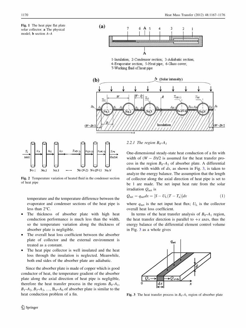
Figure 1 shows a heat pipe flat plate solar collector, which
consists of N wickless heat pipes. The evaporator sections
with length Le of the wickless heat pipes are welded to
absorber plate made of copper sheets. The condenser sec-
tions with length Lc of the wickless heat pipes are
immersed in a cooling manifold. The pitch distance
between the heat pipe is W, the heat pipe diameter is D and
the absorber plate thickness is d. The absorber plate and
heat pipe are made of copper, and the thermal conductivity
is k. The left and right sides of absorber plate which
contain point B0 and A0, respectively are adiabatic walls.
The ambient temperature is Ta. Solar intensity is Io, while
the solar energy intensity absorbed by absorber plate
is S (without glass cover: S = Ioa; with glass cover:
S = Io(as), where a is absorptivity of absorber plate and
heat pipe wall, s is transmissivity of glass cover. This study
will discuss the case with glass cover). The wall temper-
ature of each heat pipe region A1–B1, A2–B2, A3–B3,…, AN–
BN is assumed to be uniform, which are Tb1, Tb2, Tb3, …,
TbN, respectively. All these temperatures are unknown and
require to be solved.
As displayed in Fig. 2, for a collector with N heat pipes,
the heated fluid flows orderly through the condenser sec-
tions from the 1st heat pipe to the Nth one in a crosswise
manner. The heated fluid outlet temperature of the 1st
condenser section of heat pipe equals to the heated fluid
inlet temperature of the 2nd one, and so on. The final
temperature of heated fluid through N heat pipes is T0N,
which needs to be solved, and the heated fluid inlet tem-
perature Ti is a known quantity.
2.2 Theoretical analysis
For the energy balance equation and its solution for the
heat pipe collector as shown in Fig. 1, some hypotheses
have been made:
• The system is in quasi-steady state.
• The phase change of the working fluid inside the
wickless heat pipe occurs at approximately constant
Heat Mass Transfer (2012) 48:1167–1176 1169
123
temperature and the temperature difference between the
evaporator and condenser sections of the heat pipe is
less than 2�C.
• The thickness of absorber plate with high heat
conduction performance is much less than the width,
so the temperature variation along the thickness of
absorber plate is negligible.
• The overall heat loss coefficient between the absorber
plate of collector and the external environment is
treated as a constant.
• The heat pipe collector is well insulated and the heat
loss through the insulation is neglected. Meanwhile,
both end sides of the absorber plate are adiabatic.
Since the absorber plate is made of copper which is good
conductor of heat, the temperature gradient of the absorber
plate along the axial direction of heat pipe is negligible,
therefore the heat transfer process in the regions B0–A1,
B1–A2, B2–A3, …, BN–A0 of absorber plate is similar to the
heat conduction problem of a fin.
2.2.1 The region B0–A1
One-dimensional steady-state heat conduction of a fin with
width of (W - D)/2 is assumed for the heat transfer pro-
cess in the region B0–A1 of absorber plate. A differential
element with width of dx, as shown in Fig. 3, is taken to
analyze the energy balance. The assumption that the length
of collector along the axial direction of heat pipe is set to
be 1 are made. The net input heat rate from the solar
irradiation Qnet is
Qnet ¼ qnetdx ¼ ½S� ULðT � TaÞ�dx ð1Þ
where qnet is the net input heat flux; UL is the collector
overall heat loss coefficient.
In terms of the heat transfer analysis of B0–A1 region,
the heat transfer direction is parallel to ?x axes, thus the
energy balance of the differential element control volume
in Fig. 3 as a whole gives
Fig. 1 The heat pipe flat plate
solar collector. a The physical
model; b section A–A
Fig. 2 Temperature variation of heated fluid in the condenser section
of heat pipe
Fig. 3 The heat transfer process in B0–A1 region of absorber plate
1170 Heat Mass Transfer (2012) 48:1167–1176
123
Qx þ Qnet ¼ Qxþdx ð2Þ
In accordance with the Fourier’s law of heat conduction
and in combination with Eqs. 1, 2 would be
d2T
dx2þ S� ULðT � TaÞ
kd¼ 0 ð3Þ
The general solution of Eq. 3 is
T ¼ C0;1 expðmxÞ þ C0;2 expð�mxÞ þ ðS=UL þ TaÞ ð4Þ
where C0,1 and C0,2 are integration constants, m ¼ffiffiffiffiffiffiffiffiffiffiffiffiffiffiffiffiffi
UL=ðkdÞp
.
The corresponding boundary conditions (the point B0 is
coordinate origin) are
dT
dx
�
�
�
�
x¼0
¼ 0; T jx¼ðW�DÞ=2¼ Tb1 ð5Þ
Thus
C0;1 ¼ C0;2 ¼Tb1 � ðS=UL þ TaÞ
2chðmH=2Þ ð6Þ
where H = W - D.
Substituting Eq. 6 into Eq. 4, the final solution for the
temperature distribution is then
T ¼ chðmxÞchðmH=2Þ Tb1 � ðS=UL þ TaÞ½ � þ S=UL þ Ta ð7Þ
The heat flow rate which enters into the vertical plane
that contains point A1 by conduction can be expressed as
QA1 ¼ �kdLe
dT
dx
�
�
�
�
x¼H=2
¼ 1
2HLeF S� ULðTb1 � TaÞ½ � ð8Þ
where F is the standard fin efficiency for straight fins with
rectangular profile, and obtained from F ¼ ½thðmH=2Þ�=ðmH=2Þ.
2.2.2 The region B1–A2
When the heated fluid flows through the condenser of the
1st heat pipe to the Nth one successively, the temperature
of heated fluid gradually goes up. Accordingly, the working
fluid temperature of heat pipe rises up, from Thp1 to Thpn.
Heat flow directions of the regions B1–A2, B2–A3, B3–A4,
…, BN-1–AN are reverse to ?x axes. In a similar manner,
the heat transfer process in region B1–A2 of absorber plate
can be considered as one dimension steady-state heat
conduction problem of a fin with width of (W - D).
Combining the thermal conduction equation Eq. 3 with
boundary conditions x = 0, T = Tb1; x = W - D,
T = Tb2, the integration constants of Eq. 4 are obtained
C1;2 ¼½Tb1 � ðS=UL þ TaÞ� expðmHÞ
2shðmHÞ� ½Tb2 � ðS=UL þ TaÞ�
2shðmHÞ ;
C1;1 ¼ Tb1 � C1;2 � ðS=UL þ TaÞ
ð9Þ
The heat flow rate into the vertical plane that contains
point B1 is calculated by
QB1 ¼ �kdLe
dT
dx
�
�
�
�
x¼0
¼ �kdmLeðTb1 � 2C1;2 � S=UL � TaÞ
ð10Þ
On the basis of the temperature distribution of region
B1–A2 in absorber plate, the heat flow rate out of the
vertical plane that contains point A2 is written as
QA2 ¼ �kdLe
dT
dx
�
�
�
�
x¼W�D
¼ �kdmLe C1;1 expðmHÞ � C1;2 expð�mHÞ� �
ð11Þ
2.2.3 The region A1–B1 of No.1 heat pipe
The gained solar energy in the region A1–B1 of No.1 heat
pipe is
QA1B1 ¼ ðp=2ÞDLe S� ULðTb1 � TaÞ½ � ð12Þ
The useful energy obtained by the No.1 heat pipe is
Qhp1 ¼ GCpðT01 � TiÞ ð13Þ
where T01 is heated fluid outlet temperature of No.1 heat
pipe.
The energy balance of the region A1–B1 of No.1 heat
pipe as a whole gives
QA1 þ QA1B1 þ QB1j j ¼ Qhp1 ð14Þ
Then the following equation can be obtained,
ð1=2ÞHLeF S�ULðTb1�TaÞ½ �þðp=2ÞDLe½S�ULðTb1�TaÞ�þkdmLeðTb1�2C1;2�S=UL�TaÞ¼GCpðT01�TiÞ
ð15Þ
Equation 15 contains unknown temperature Tb1, Tb2,
T01.
2.2.4 The region An–Bn of No.n (n = 2, 3, 4,…, N - 1)
heat pipe
For the region An–Bn of No.n (n = 2, 3, 4,…, N - 1) heat
pipe, the heat transfer process of each region is similar.
Applying the analysis method of the region A1–B1, we also
have
Heat Mass Transfer (2012) 48:1167–1176 1171
123

kdmLeðTbn � 2Cn;2 � S=UL � TaÞþ ðp=2ÞDLe½S� ULðTbn � TaÞ�¼ GCPðT0n � T0ðn�1ÞÞ þ kdmLe½Cn�1;1 expðmHÞ� Cn�1;2 expð�mHÞ� ð16Þ
where
Cn�1;2 ¼½Tbðn�1Þ � ðS=UL þ TaÞ� expðmHÞ
2shðmHÞ� ½Tbn � ðS=UL þ TaÞ�
2shðmHÞ ð17aÞ
Cn�1;1 ¼ Tbðn�1Þ � Cðn�1Þ;2 � ðS=UL þ TaÞ ð17bÞ
Cn;2 ¼½Tbn � ðS=UL þ TaÞ� expðmHÞ
2shðmHÞ
�½Tbðnþ1Þ � ðS=UL þ TaÞ�
2shðmHÞn 2 ð2; 3; 4; 5; . . .. . .;N � 1Þ
ð17cÞ
In which, Tb(n-1) is the region An-1–Bn-1 temperature of
No.(n - 1) heat pipe; Tbn is the region An–Bn temperature
of No.n heat pipe; Tb(n?1) is the region An?1–Bn?1
temperature of No.(n ? 1) heat pipe; T0(n-1) is heated
fluid inlet temperature of No.n heat pipe. T0n is heated fluid
outlet temperature of No.n heat pipe. Among these, Tb(n-1),
Tbn, T0(n-1) and T0n are unknown.
2.2.5 The region AN–BN of No.N heat pipe
Since the analysis method of the region AN–BN of
No.N heat pipe is almost the same as that of the region A1–
B1 of No.1 heat pipe except for different boundary condi-
tions, thus neglected for brevity’s sake. The right side
surface of absorber plate is adiabatic. The appropriate
boundary conditions (the point BN is coordinate origin)
would be
T jx¼0¼ TbN ;dT
dx
�
�
�
�
x¼ðW�DÞ=2
¼ 0 ð18Þ
Therefore, application of the above boundary conditions
yields the integration constants of general solution Eq. 4 as
CN;1 ¼TbN � ðS=UL þ TaÞ
1þ expðmHÞ ;
CN;2 ¼ TbN � CN;1 � ðS=UL þ TaÞð19Þ
The heat flow rate into the vertical plane that contains
point BN is calculated by
QBN ¼ �kdLe
dT
dx
�
�
�
�
x¼0
¼ �kdmLeðCN;1 � CN;2Þ ð20Þ
The energy balance equation for the region AN–BN of
No.N heat pipe is written as
QBNj j þ QANBN ¼ QANj j þ QhpN ð21Þ
where QANBN is the gained solar energy in the region AN–
BN of No.N heat pipe; QAN is the heat flow rate out of the
vertical plane that contains point AN.
The useful energy gained by the No.N heat pipe is given
by
QhpN ¼ GCp T0N � T0ðN�1Þ� �
ð22Þ
Combining Eqs. 20, 21 and 22 leads to:
kdmLeð2CN;1 � TbN þ S=UL þ TaÞþ ðp=2ÞDLe½S� ULðTbN � TaÞ�¼ GCpðT0N � T0ðN�1ÞÞ þ kdmLe½CN�1;1 expðmHÞ� CN�1;2 expð�mHÞ� ð23Þ
It is clear that Eq. 23 contains unknown temperature
Tb(N-1), TbN, T0(N-1) and T0N.
2.2.6 The relation T0n with Tbn
For No.1 heat pipe, the heat transfer effectiveness e1 and
the number of heat transfer unit NTUc1 are defined as
e1 ¼ 1� expð�NTUc1Þ; NTUc1 ¼ ðAc1Uc;01Þ=ðGCPÞð24Þ
where Uc,01 is heat convection coefficient of heated fluid
and the condenser section, it can be obtained from
Nu = 0.26Re0.6Pr1/3 [22]; Ac1 is the heat exchange area of
heated fluid and the condenser section of heat pipe.
From e1 ¼ ðT01 � TiÞ=ðTc;01 � TiÞ, we have
T01 ¼ Ti þ ½1� expð�NTUc1Þ�ðTc;01 � TiÞ ð25Þ
where Tc,01 is the working fluid temperature of No.1 heat
pipe condenser section and equal to the working fluid
temperature of No.1 heat pipe Thp1. Considering that phase
transition heat transfer coefficient of heat pipe is rather high,
and the temperature difference of phase transition heat
transfer is much smaller than that of single phase
convection heat transfer, namely, Tc,01 = Thp1 & Tb1.
Therefore, Eq. 25 may be rearranged in the following form:
T01 ¼ Ti þ ½1� expð�NTUc1Þ�ðTb1 � TiÞ ð26Þ
Proceeding in a similar fashion, for No.n heat pipe
(n = 2, 3, 4,…, N), it is readily shown that
T0n ¼ T0ðn�1Þ þ 1� expð�NTUcnÞ½ � Tbn � T0ðn�1Þ� �
ð27Þ
Again,
en ¼ 1� expð�NTUcnÞ; NTUcn ¼ ðAcnUc;0nÞ=ðGCPÞð28Þ
It is assumed that each heat pipe is the same, namely
Acn = Ac1, Uc,01 = Uc,0n, we have
1172 Heat Mass Transfer (2012) 48:1167–1176
123
e1 ¼ e2 ¼ e3 ¼ e4 ¼ � � � ¼ en ¼ e ð29Þ
From Eqs. 26 to 29, the following equations are
obtained:
T01 ¼ Ti þ eðTb1 � TiÞ ¼ eTb1 þ ð1� eÞTi ð30Þ
T02 ¼ eTb2 þ ð1� eÞeTb1 þ ð1� eÞ2Ti ð31Þ
T0n ¼ Tið1� eÞn þ ð1� eÞn�1eTb1 þ ð1� eÞn�2eTb2
þ � � � þ ð1� eÞeTbðn�1Þ þ eTbn ð32Þ
where n 2 ð2; 3; 4; . . .;NÞ.From the relation T0n with Tbn, it is shown that Eqs. 15,
16 and 23 consist of N equations which contain N unknown
quantities. Obviously, closed form solutions can be
obtained from these equations. Namely, we can gain the
temperature Tb1, Tb2, Tb3,…, TbN of region A1–B1, A2–B2,
A3–B3,…, AN–BN of the heat pipes. Meanwhile, the heated
fluid outlet temperature of each heat pipe T01, T02, T03,…,
T0N can be found out. Further, the thermal efficiency of the
heat pipe flat plate solar collector g can be calculated as [6]
g ¼ GCpðT0N � TiÞI0Acoll
ð33Þ
where Acoll is area of collector, Acoll = NWLe.
3 Results validation
Take the collector parameters in Ref. [6], the heat pipe was
made of copper with length of 0.92 m and outer diameter
D of 0.0127 m. The lengths of evaporator and condenser
section, i.e., Le and Lc are 0.75 and 0.1 m, respectively. The
glass cover plate was sized in 0.76 m 9 1.9 m 9 0.004 m,
of which the transmissivity s is 0.9. The absorber plate was
made of copper with size of 1.89 m 9 0.75 m and it was
coated with anodic alumina spectral selective absorption
material of which the absorptivity a is 0.94. The condenser
section of heat pipe is placed in the heated fluid channels of
1.9 m 9 0.1 m 9 0.03 m. The heated fluid, namely water
flows in succession over the condenser section of the heat
pipe in a crosswise manner. The heat loss coefficient
between the absorber plate and environment UL is 8.6
W/m2 K [23]. Other parameters, such as solar intensity Io
and ambient temperature Ta are from Ref. [6]. Initial wall
temperature distributions were assumed for each heat pipe,
then the Gauss–Seidel iteration method was employed to
solve the above mentioned N equations, and the calculation
results are discussed in the following. For the convenience
of illustration and comparison, ‘‘th’’ means the theoretical
calculations in this paper; ‘‘exp’’ and ‘‘nu’’, respectively
denote the experimental and numerical results in Ref. [6].
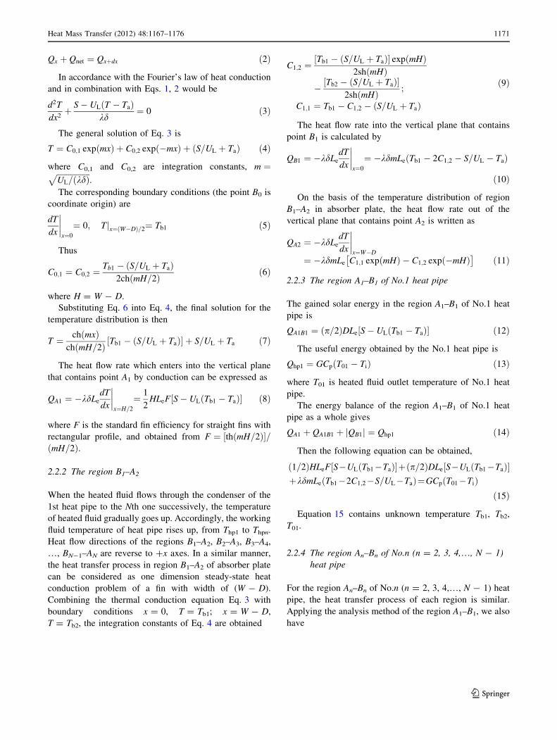
The theoretical water outlet temperature in this paper is
compared with the experimental and numerical values in
Ref. [6] when the water flow rate G = 0.0458 kg/s, as
presented in Fig. 4a. Very small relative deviation (only
-0.1 to 0.4%) has been detected. Figure 4b demonstrates
comparisons of the collector thermal efficiency for the
same case. The relative deviation between theoretical and
experimental values is only -1.7 to 7.5%, while the rela-
tive deviation between the numerical and experimental
values in Ref. [6] was found to be -4.5 to 6.6%.
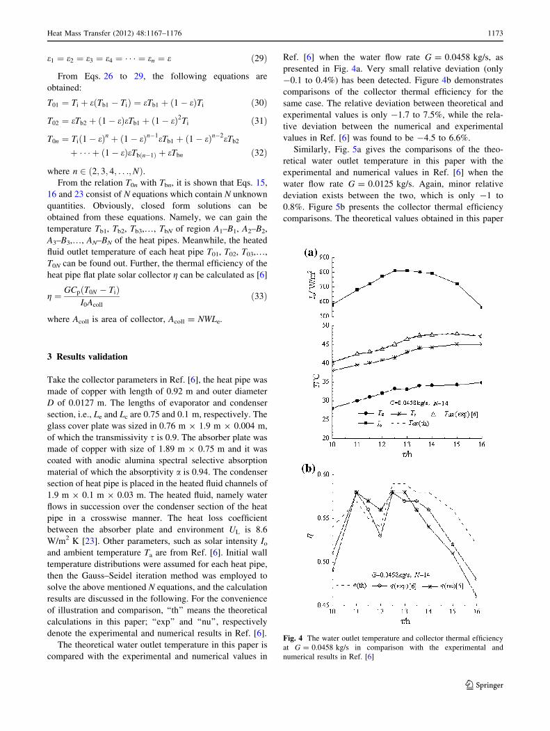
Similarly, Fig. 5a gives the comparisons of the theo-
retical water outlet temperature in this paper with the
experimental and numerical values in Ref. [6] when the
water flow rate G = 0.0125 kg/s. Again, minor relative
deviation exists between the two, which is only -1 to
0.8%. Figure 5b presents the collector thermal efficiency
comparisons. The theoretical values obtained in this paper
Fig. 4 The water outlet temperature and collector thermal efficiency
at G = 0.0458 kg/s in comparison with the experimental and
numerical results in Ref. [6]
Heat Mass Transfer (2012) 48:1167–1176 1173
123

agree well with the experimental values with relative
deviation of -5.2 to 5.8%. Whereas, the relative deviation
of the numerical and experimental values in Ref. [6] was
-4.9 to 29.2%.
According to the above analysis, fairly good agreements
have been observed in the theoretical and experimental
results, especially the water outlet temperature. This con-
firms that the theoretical method raised in this paper is
feasible and effective, and can be used with confidence for
the thermal performance analysis of heat pipe flat plate
solar collector.
In addition, seen from the theoretical values of water
outlet temperature and the collector thermal efficiency in
this paper and the experimental values in Ref. [6], the
relative deviation of collector thermal efficiency is always
greater than that of water outlet temperature. For example,
at 16:00 in Fig. 4, the water outlet temperature calculated
in this paper is only 0.3% higher than the experiment value
in Ref. [6], while the relative deviation of thermal effi-
ciency is enlarged to 7.5%. This is due to that, for the
calculation of relative deviation of water outlet tempera-
ture, it is defined as the calculated and experimental water
outlet temperature difference divided by the experimental
value. The relative deviation of collector thermal efficiency
is defined as the calculated and experimental water outlet
temperature difference divided by the actual water tem-
perature rise. Because the water temperature rise in actual
process is not too much (in Ref. [6], it is only several
Celsius degree), a small deviation of water outlet temper-
ature will result in great thermal efficiency deviation,
especially for the cases of weak solar radiation or increased
water mass flow rate. Compared Fig. 4 with Fig. 5, it is
noticed that as the water mass flow rate increases, the
thermal efficiency deviation of the theoretical and experi-
mental value increases, which is owning to that the
increase of water mass flow rate leads to the decrease of
water temperature rising. This also confirms the above
analysis.
To further validate the theoretical method proposed in
this paper, comparisons of water outlet temperature and
collector thermal efficiency between the theoretical and
experimental results in Ref. [6] for the collector with dif-
ferent heat pipe number and the water mass flow rate
G = 0.0292 kg/s have been presented in Fig. 6. It suggests
that as the heat pipe number increases, the theoretical
results obtained by the present method become closer to the
experimental results in Ref. [6]. With N = 10, 12 and 14,
the relative deviations of water outlet temperature are 1.56
to 2.4%, -0.83 to -1.97%, -0.91 to 1.4%, and the relative
deviations for collector thermal efficiency are 16.7 to 38%,
-8 to -14%, -6.8 to 13.9%. It should be noted that, the
collector thermal efficiency showed the highest when
N = 12 in Ref. [6]. However, the theoretical results in this
paper reveal that, the collector thermal efficiency increase
slightly as the heat pipe number decreases, namely, the
collector thermal efficiency does not change significantly if
the heat pipe number changes a little. Take the moment of
12:30 as an example, for the collector with N = 10, 12 and
14, their thermal efficiencies are 64, 63, 61%, respectively;
however, the results in Ref. [6] stated that the collector
thermal efficiencies respectively are 54, 70, and 64% with
N = 10, 12 and 14, which shows much more significant
change than that of this paper.
4 Conclusions
The equations describing the temperature distributions of
the absorber plate and the relationships between each heat
Fig. 5 The water outlet temperature and collector thermal efficiency
at G = 0.0125 kg/s in comparison with the experimental and
numerical results in Ref. [6]
1174 Heat Mass Transfer (2012) 48:1167–1176
123

pipe wall temperature and the water temperature rise in the
process of flowing over the condenser section of each heat
pipe were derived. The theoretical values of water outlet
temperature and the collector thermal efficiency have been
calculated when the relevant parameters, such as the solar
intensity, water inlet temperature and environmental tem-
perature are known. On the basis of present analysis it is
concluded that:
1. Using the present theoretical method, the values of water
outlet temperature and the collector thermal efficiency
agree well with those in Ref. [6], especially the water
outlet temperature values. Because of the collector
thermal efficiency definition, the relative deviation of
collector thermal efficiency is generally greater than that
of water outlet temperature.
2. As an increased the heated fluid temperature rise can
reduce the relative deviation of water outlet temper-
ature and collector thermal efficiency, this theoretical
method is more suitable for the collector under certain
conditions, i.e., intense solar radiation, small heated
fluid mass flow rate, and a collector with more heat
pipes.
3. The theoretical method proposed in this paper can be
used for heat pipe flat plate solar collector performance
analysis and assessment. It is an efficient approach to
analyze and discuss the influences of solar intensity,
water inlet temperature, environmental temperature,
heated fluid mass flow rate and collector’s structure
parameters on the heat pipe flat plate solar collector
performance.
Acknowledgments This work is supported by National Natural
Science Foundation of China (Project No.51076171). The authors
also wish to thank the support from Natural Science Foundation
Project of CQ CSTC (CSTC, 2010BB6062) and Project No. CDJXS
10141147 supported by Fundamental Research Funds for the Central
Universities.
References
1. Hussein HMS, El-Ghetany HH, Nada SA (2006) Performance of
wickless heat pipe flat plate solar collectors having different pipes
cross sections geometries and filling ratios. Energy Convers
Manag 47(11–12):1539–1549
2. Hussein HMS, Mohamad MA, El-Asfouri AS (1999) Transient
investigation of a thermosyphon flat plate solar collector. Appl
Therm Eng 19(7):789–800
3. Hussein HMS, Mohamad MA, El-Asfouri AS (1999) Optimiza-
tion of a wickless heat pipe flat plate collector. Energy Convers
Manag 40(18):1949–1961
4. Hussein HMS (2002) Transient investigation of a two phase
closed thermosyphon flat-plate solar water heater. Energy Con-
vers Manag 43(18):2479–2492
5. Hussein HMS (2003) Optimization of a natural circulation two
phase closed thermosyphon flat plate solar water heater. Energy
Convers Manag 44(14):2341–2352
6. Hussein HMS (2007) Theoretical and experimental investigation
of wickless heat pipes flat plate solar collector with cross flow
heat exchanger. Energy Convers Manag 48(4):1266–1272
7. Riffat SB, Doherty PS, Abdel Aziz EI (2000) Performance testing
of different types of liquid flat plate collectors. Int J Energy Res
24(13):1203–1215
8. Riffat SB, Zhao X, Doherty PS (2002) Analytical and numerical
simulation of the thermal performance of ‘mini’ gravitational and
‘micro’ gravitational heat pipes. Appl Therm Eng 22(9):1047–
1068
9. Riffat SB, Zhao X (2004) A novel hybrid heat pipe solar col-
lector/CHP system—part I: system design and construction.
Renew Energy 29(15):2217–2233
10. Riffat SB, Zhao X (2004) A novel hybrid heat-pipe solar col-
lector/CHP system—part II: theoretical and experimental inves-
tigations. Renew Energy 29(12):1965–1990
Fig. 6 The water outlet temperature and collector thermal efficiency
at N = 10, 12, 14 in comparison with the experimental and numerical
results in Ref. [6]
Heat Mass Transfer (2012) 48:1167–1176 1175
123

11. Riffat SB, Zhao X, Doherty PS (2005) Developing a theoretical
model to investigate thermal performance of a thin membrane
heat-pipe solar collector. Appl Therm Eng 25(5–6):899–915
12. Nada SA, El-Ghetany HH, Hussein HMS (2004) Performance of
a two-phase closed thermosyphon solar collector with a shell and
tube heat exchanger. Appl Therm Eng 24(13):1959–1968
13. Abu-Zour AM, Riffat SB, Gillott M (2006) New design of solar
collector integrated into solar louvers for efficient heat transfer.
Appl Therm Eng 26(16):1876–1882
14. Yu ZT, Hu YC, Hong RH, Cen KF (2005) Investigation and
analysis on a cellular heat pipe flat solar heater. Heat Mass Transf
42(2):122–128
15. Rittidech S, Wannapakne S (2007) Experimental study of the
performance of a solar collector by closed-end oscillating heat
pipe (CEOHP). Appl Therm Eng 27(11–12):1978–1985
16. Rittidech S, Donmaung A, Kumsombut K (2009) Experimental
study of the performance of a circular tube solar collector with
closed-loop oscillating heat-pipe with check valve (CLOHP/CV).
Renew Energy 34(10):2234–2238
17. Esen M, Esen H (2005) Experimental investigation of a
two-phase closed thermosyphon solar water heater. Sol Energy
79(5):459–468
18. Facao J, Oliveira AC (2005) The effect of condenser heat transfer
on the energy performance of a plate heat pipe solar collector. Int
J Energy Res 29(10):903–912
19. Azad E (2008) Theoretical and experimental investigation of heat
pipe solar collector. Exp Thermal Fluid Sci 32(8):1666–1672
20. Azad E (2009) Performance analysis of wick-assisted heat pipe
solar collector and comparison with experimental results. Heat
Mass Transf 45(5):645–649
21. Hottel HC, Willier A (1955) Evaluation of flat plate solar col-
lector performance. In: Transactions of conference on the use
of solar energy, vol II, thermal processes. University of Arizona,
Arizona, pp 74–104
22. Chi SW (1976) Heat pipe theory and practice. Hemisphere
Publishing Corp, Washington
23. Sodha MS (2006) Performance evaluation of solar PV/T system:
an experimental validation. Sol Energy 80:751–759
1176 Heat Mass Transfer (2012) 48:1167–1176
123