theoretical elements of electrical engineering;
TRANSCRIPT


Jltl;ara, l^tm ^nrk
ALEXANDER GRAY MEMORIALLIBRARY
ELECTRICAL ENGINEERING
THE GIFT OF
D. S. Kimball

TK i45.s§53""""'™™"v'-"'™ry
^miwilim™'"*"'® °' «'ec*"cal engin
3 1924 004 249 110

Cornell University
Library
The original of this book is in
the Cornell University Library.
There are no known copyright restrictions in
the United States on the use of the text.
http://www.archive.org/details/cu31924004249110


Theoretical Elements
of
Electrical Engineering
By
Charles Proteus Steinmetz
New York:
Electrical World and Engineer(Incorporated)

COPVRIGHTED; 1901 , BY
ELECTRICAL WORLD AND ENGINEER
Nhw York
TntOGRAPHT EV C. J. PETfEES * SOS
BOSTON, U.S.A.

PREFACE.
The first part of the following volume originated from a
series of University lectures which I once promised to deliver.
This part can, to a certain extent, be considered as an in-
troduction to my work on "Theory and Calculation of
Alternating Current Phenomena," leading up very gradually
from the ordinary sine wave representation of the alternating
current to the graphical representation by polar coordinates,
from there to rectangular components of polar vectors, and
ultimately to the symbolic representation by the complex
quantity. The present work is, however, broader in its
scope, in so far as it comprises the fundamental principles
not only of alternating, but also of direct currents.
The second part is a series of monographs of the more
important electrical apparatus, alternating as well as direct
current. It is, in a certain respect, supplementary to "Al-
ternating Current Phenomena." While in the latter work I
have presented the general principles of alternating current
phenomena, in the present volume I intended to give a
specific discussion of the particular features of individual
apparatus. In consequence thereof, this part of the book
is somewhat less theoretical, and more descriptive, my inten-
tion being to present the most important electrical apparatus
in all their characteristic features as regard to external and
internal structure, action under normal and abnormal condi-
tions, individually and in connection with other apparatus, etc.
I have restricted the work to those apparatus which ex-
perience has shown as of practical importance, and give only

IV PREFACE.
those theories and methods which an extended experience
in the design and operation has shown as of piractical utility.
I consider this the more desirable as, especially of late years,
electrical literature has been haunted by so many theories
(for instance of the induction machine) which are incorrect,
or too complicated for use, or valueless in practical applica-
tion. In the class last mentioned are most of the graphical
methods, which, while they may give an approximate insight
in the inter-relation of phenomena, fail entirely in engineering
practice owing to the great difference in the magnitudes of
the vectors in the same diagram, and to the synthetic method
of graphical representation, which generally requires one
to start with the quantity which the diagram is intended to
determine.
I originally intended to add a chapter on Rectifying Ap-
paratus, as arc light machines and alternating current recti-
fiers, but had to postpone this, due to the incomplete state
of the theory of these apparatus.
The same notation has been used as in the Third Edition
of "Alternating Current Phenomena," that is, vector quanti-
ties denoted by dotted capitals. The same classification
and nomenclature have been used as given by the report of
the Standardizing Committee of the American Institute of
Electrical Engineers.

CONTENTS.
PART I.
GENERAL THEORY.PAGE
1. Magnetism and Electric Current 1
4 examples 5
2. Magnetism and E.M.F 9
2 examples 10
3. Induction of E.M.F's 11
3 examples 14
4. Effect and Effective Values 15
3 examples 16
5. Self-Induction and Mutual Induction 18
2 examples . 21
6. Self-induction of Continuous Current Circuits ... . . 22
5 examples 26
7. Self-induction in Alternating Current Circuits 29
2 examples .34
8. Effect of Alternating Currents SS
1 example . . 41
9. Polar Coordinates . . ... . . 41
1 example 45
10. Hysteresis and Effective Resistance . . . .... 48
1 example ... 53
11. Capacity and Condensers 55
1 example .
"8
12. Impedance of Transmission Lines 58
2 examples <)5
13. Alternating Current Transformer 09
1 example 77
14. RectangularCoordinates 79
3 examples 85
15. Load Characteristic of Transmission Line 89
1 example 93
16. Phase Control of Transmission Lines ......... 04
2 examples 99
V

vi CONTENTS.PAGE
17. Impedance and Admittance 103
2 examples 108
18. Equivalent Sine Waves 112
1 example ll'l
PART II.
SPECIAL APPARATUS.
Introduction. Classification and Nomenclature of Apparatus 121
A. Synchronous Machines 126-161
I. General 126
II. E.M.F.'s 128
III. Armature Reaction 129
IV. Self-Induction 133
V. Synclironous Reactance 136
VI. Characteristic Curves of Alternating Current Generator . 139
VII. Synchronous Motor 141
VIII. Characteristic Curves of Synchronous Motor 143
IX. Magnetic Characteristic or Saturation Curve 147
X. Efficiency and Losses ICO
XI. Unbalancing of Polyphase Synchronous Machines . . . 151
XII. Starting of Synchronous Motors 153
XIII. Parallel Operation 154
XIV. Division of Load in Parallel Operation 156
XV. Fluctuating Cross-Currents in Parallel Operation .... 157
B. Commutating Machines 162-216
I. General 162
II. Armature Winding 165
III. Induced E.M.F.'s 175
IV. Distribution of Magnetic Flux 177
V. Effect of Saturation on Magnetic Distribution 181
VI. Effect of Slots on Magnetic Flux 184
VII. Armature Reaction 187
VIII. Saturation Curves 188
IX. Compounding 190
X. Characteristic Curves 192
XI. Efficiency and Losses 193
XII. Commutation 193
XIII. Types of Commutating Machines . j 202
A. Generators. Separately excited and Magneto,
Shunt, Series, Compound 205
B. Motors. Shunt, Series, Compound 212

CONTENTS. vii
PAGEC. Synchronous Converters 217-260
I. General 217
II. Ratio of E.M.F.'s and of Currents 218III. Variation of the Ratio of E.M.F.'s 225IV. Armature Current and Heating 228
V. Armature Reaction .... 286VI. Wattless Currents and Compounding 242
VII. Starting 244VIII. Inverted Converters 240
IX. Double Current Generators 248
X. Conclusion 250
Appendix. Direct Current Converter 251
J). Induction Machines 261-320
I. General 261
II. Polyphase Induction Motor.
1. Introduction 205
2. Calculation 260
3. Load and Speed Curves 272
4. Effect of Armature Reaction and Starting.... 277
III. Single-phase Induction Motor.
1. Introduction 281
2. Load and Speed Curves 286
3. Starting Devices of Single-phase Motors .... 290
4. Acceleration vifith StartingDevice 295
IV. Induction Generator.
1. Introduction 297
2. Constant Speed Induction or Asynchronous Gene-
rator 299
3. Power Factor of Induction Generator 301
V. Induction Booster 307
VI. Phase Converter 309
VII. Frequency Converter or General Alternating Current
Transformer 312
VIII. Concatenation of Induction Motors 315


PART I.
GENERAL THEORY.
1. MAGNETISM AND ELECTRIC CURRENT.
A magnet pole attracting (or repelling) another magnet
pole of equal strength at unit distance with unit force * is
called a tmit magnet pole.
The space surrounding a magnet pole is called a mag-
netic field offorce, or magnetic field.
The magnetic field at unit distance from a unit magnet
pole is called a unit magnetic field, and is represented by
one line of magnetic force (or shortly " one line ") per cm'',
and from a unit magnet pole thus issue a total of 4 ir lines
of magnetic force.
The total number of lines of force issuing from a magnet
pole is called its magnetic flux.
The magnetic flux "t of a magnet pole of strength m is,
At the distance R from a magnet pole of strength ;«,
and therefore of flux $ = 47r»«, the magnetic field has the
intensity,
since the $ lines issuing from the pole distribute over the
area of a sphere of radius R, that is the area 4 ttR^.
* That is, at 1 cm distance witli such force as to give to the mass of 1 gramme the
acceleration of 1 cm per second.

2 ELECTRICAL ENGINEERINC
A magnetic field of intensity 3C exerts upon a magnet
pole of strength ni the force,
m'K..
Thus two magnet poles of strengths Wj and m^ and dis-
tance R, exert upon each other the force,
Electric currents produce magnetic fields also. That is,
the space surrounding the conductor carrying an electric
current is a magnetic field, which appears and disappears
and varies with the current producing it, ahd is indeed an
essential part of the phenomenon called an electric current.
Thus an electric current represents a magnetomotive
force (M.M.F.).
The magnetic field of a straight conductor consists of
lines of magnetic force surrounding the conductor in con-
centric circles. The intensity of this magnetic field is pro-
portional to the current strength and inversely proportional
to the distance from the conductor.
Unit current is the current which in a straight conductor
produces unit field intensity at unit distance from the con-
ductor, that i-s, one line per cm^ in the magnetic circuit of
2 ir cm. length surrounding the conductor as concentric
circle, or twice this field intensity at unit distance from a
closed current loop, that is a turn, consisting of conductor
and return conductor.
One-tenth of unit current is the practical unit, called one
ampere.
One ampere-turn thus produces at unit distance from the
conductor the field intensity .2, and at distance R the field
.2intensity -^ , and ff ampere-turns the field intensities 3C = . 2 JF
.2fFand 3C = —5- , respectively.
•S, that is, the product of amperes and turns, is called
magnetomotive force (M.M.F.).
MAGNETISM AND ELECTRIC CURRENT. 3
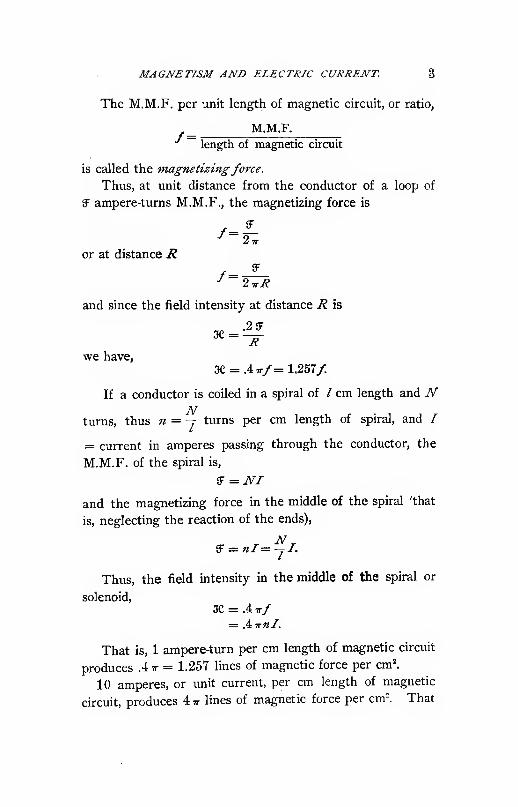
The M.M.F. per unit length of magnetic circuit, or ratio,
M.M.I",
length of magnetic circuit
is called the magnetizingforce.
Thus, at unit distance from the conductor of a loop of
'S ampere-turns M.M.F., the magnetizing force is
or at distance R/=;
and since the field intensity at distance R is
we have,
3C = .4,r/=1.257/.
If a conductor is coiled in a spiral of / cm length and NN
turns, thus « = y turns per cm length of spiral, and /
= current in amperes passing through the conductor, the
M.M.F. of the spiral is,
S = NI
and the magnetizing force in the middle of the spiral 'that
is, neglecting the reaction of the ends),
Thus, the field intensity in the middle of the spiral or
solenoid,
3e = .4 t/= .iirnl.
That is, 1 ampere-turn per cm length of magnetic circuit
produces .4ir = 1.257 lines of magnetic force per cm^
10 amperes, or unit current, per cm length of magnetic
circuit, produces 4 tt lines of magnetic force per cm". That

4 ELECTRICAL ENGINEERING.
is, tmit current is the current which, when acting upon a
magnetic circuit (in air) of unit length (or 1 cm), produces
the same number of Hnes of magnetic force per cm^, (4 tt),
as issue altogether from a unit magnet pole.
M.M.F. JF applies to the total magnetic circuit, or part of
the magnetic circuit. It is measured in ampere-turns.
Magnetizing force f is the' M.M.F. per unit length of
magnetic circuit. It is measured in ampere-turns per cm.
Field intensity 3e is the number of lines of force per cm^.
If / = length of magnetic circuit or part of magnetic
circuit,
^ = lf /=^
3C = .4./ /=-|^
= 1.257/ /=.796aC.
The preceding applies only to magnetic fields in air or
other unmagnetic materials.
If the medium in which the magnetic field is established
is a "magnetic material," the number of lines of force per
cm^ is different and usually many times greater. (Slightly
less in diamagnetic materials.)
The ratio of the number of lines of force in a medium,
to the number of lines of force which the same magnetizing
force would produce in air (or rather in a vacuum), is called
the permeability or magnetic conductivity fi of the medium.
The number of lines of force per cm^ in a magnetic
medium is called the magnetic induction (B. The number
of lines of ibxct produced by the same magnetizing force in
air is called the field intensity 3C.
In air, magnetic induction (B and field intensity 3C are
equal.
As a rule, the magnetizing force in a magnetic circuit is
changed by the introduction of a magnetic material, due to
the change of distribution of the magnetic flux.
The permeability of air = 1 and is constant

MAGNETISM AND ELECTRIC CURRENT. 5
The permeability of iron and other magnetic materials
varies with the magnetizing force between a little above 1
and about 4000 in soft iron.
The magnetizing force/ in a medium of permeability /*
produces the field intensity 3C == .4 t/ and the magnetic
induction 05 = .4 tt/a/
EXAMPLES.
(1.) To hold a horizontal bar magnet of 12 cm length,
pivoted in its center, in a position at, right angles to the
magnetic meridian, a pull is required of ,2 grams at 4 cmradius. What is the intensity of the poles of the magnet,
and the number of; lines of^magnetic force issuing from each
pole, if the horizontal intensity of the. terrestrial magnetic
field 3C = .2, and the acceleration of gravity = 980 1
As distance of the poles of tjie' bar magnet may be
assumed | of its length.
Let m = intensity of magnet p6le. r = 5 is the radius
on which the terrestrial magnetism acts.
Thus "2mKr = ~'Zm = torque exerted by the terrestrial
magnetism.
2 grams weight = 2 X 980 = 1960 uiiits of force: These
at 4 cm radius give the torque 4 X 1960 =.7840.'
Hence 2»« = 7840.
in = 3920 is the strength of each magnet pole and
4> = -iirm = 49000, the number of lines of force issuing
from each pole.
(2.) A conductor carrying 100 amperes runs in the direc-
tion of the magnetic meridian. What position will a com-
pass needle assume, when held vertically below the conductor
at a distance of 50 cm, if the intensity of the terrestrial
magnetic field is .2 .?
The intensity of the magnetic field of 100 amperes 50 cm•2/ o 100 , ^ ,.
from the conductor is 3C = -^ = .2 X -^ = A, the direc-
tion is at right • angles to the conductor, that is at right
angles to the terrestrial magnetic field.

6 ELECTRICAL ENGINEERING.
li <t>= angle between compass needle and the north pole
of magnetic meridian, / = length of needle, m — intensity
of its magnet pole, the torque of the terrestrial magnetism
is 3Cm/ sin <l>= .2 m/ sin <t>, the torque of the current is
. 2 Im I cos ^ , ,5 = .4 ml cos 9.K.
In equilibrium, .2ml sin <^ = .4 w/ cos <^, or tan <^ = 2,
</. = 63.4°.
(3.) What is the total magnetic flux per /=1000 mlength, passing between the conductors of a long distance
transmission line carrying / amperes of current, if ^= .82
cm is the diameter of the conductors (No. B. & S. G.),
Z? = 45 cm their distance from each other .''
Fig. 1.
At distance x from the center of one of the conductors
(Fig. 1), the length of the magnetic circuit surrounding this
conductor is 2 irx, the M.M.F. /ampere turns ; thus the mag-
netizing force / = ^j— ) and the field intensity 3C = .4 tt/
=— , and the nux m the zone ax is at* = , andX Xthe total flux from the surface of the conductor to the next
conductor is,
2
.2//|^log,J°, = .27/log.^

MAGNETISM AND ELECTRIC CURRENT. 7
The same flux is produced by the return conductor in
the same direction, thus the total flux passing between the
transmission wires is,
2<l> = .4//loge^
or per 1000 m = 10^ cm length,
2 $ = .4 X 10^ /lege -^ = -4: X 10^ X 4.70 = .188 x 10" I,
or .188 / megalines or millions of lines per line of 1000 mof which .094 / megalines surround each of the two con-
ductors.
(4.) In an alternator each pole has to carry 6.4 millions
of lines, or 6.4 ml (megalines) magnetic flux. How many
ampere turns per pole are required to produce this flux, if
the magnetic circuit in the armature of laminated iron has
the cross section of 930 cm^ and the length of 15 cm, the
air-gap between stationary field and revolving armature has
95 cm length and 1200 cm^ section, the field-pole has 26.3
cm length and 1075 cm^ section, of laminated iron, and the
outside return circuit or yoke has a length per pole of 20
cm and 2250 cm^ section, of cast iron.?
The magnetic densities are,
In armature (Bi = 6880
In air-gap (Bj = 5340
In field-pole ffi^ = 5950
In yoke «< = 2850
The permeability of sheet iron \s> fx^= 2550 at (&^ = 6880,
f,^= 2300 at (Bg = 5950. The permeability of cast iron is
^^ = 280 at (B, = 2850.
Thus the field intensity (k = ®j is, X.^ = 2.7, X.^ = 5340,
3C3 = 2.5, 3C, = 10.2. ^'''
The magnetizing force {f^^ is, /^ = 2.15, /, = 4250,
/j = 1.99, /^ = 8.13 ampere-turns per cm.
Thus the M.M.F. (JF =//) is, JFj = 32, SF, = 4030, 5F3
= 52, £F, = 163,
8 ELECTRICAL ENGINEERING.
or the total M.M.F. per pole,
JF = iFi + SF2 + SFs + 3^4 ^ 4280 ampere-turns.
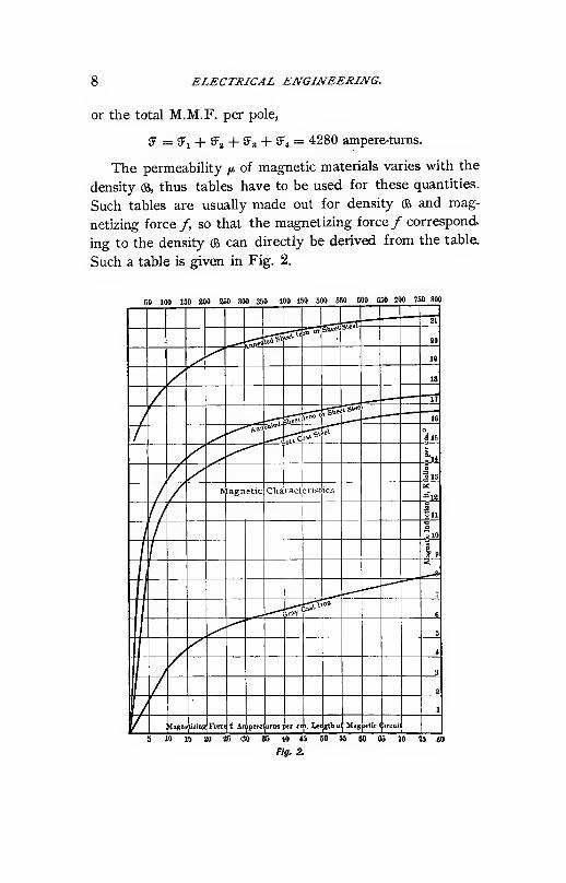
The permeability /a of magnetic materials varies with the
density (B, thus tables have to be used for these quantities.
Such tables are usually made out for density <& and mag-
netizing force/, so that the magnetizing force/ correspond,
ing to the density (B can directly be derived from the table.
Such a table is given in Fig. 2.
so 100 150 200 250 30O 350 400 450 500 550 000 650 100 150 800

MAGNETISM AND E.M.F. 9
2. MAGNETISM AND E.M.F.
In an electric conductor moving relatively to a magnetic
field, an E.M.F. is induced proportional to the rate of cutting
of the lines of magnetic force by the conductor.
Unit E.M.F. is the E.M.F. induced in a conductor cutting
one line of magnetic force per second.
10* times unit E.M.F. is the practical unit, called the
volt.
Coiling the conductor n fold increases the E.M.F. n fold,
by cutting each line of magnetic force n times.
In a closed electric circuit the E.M.F. produces an
electric current.
The ratio of E.M.F. to electric current produced thereby
is called the resistance of the electric circuit.
Unit resistance is the resistance of a circuit in which
unit E.M.F. produces unit current.
10° times unit resistance is the practical unit, called the
ohm.
The ohm is the resistance of a circuit, in which one volt
produces one ampere.
The resistance per unit length and unit section of a con-
ductor is called its resistivity, p.
The resistivity p is a constant of the material, varying
with the temperature.
The resistance r of a conductor of length /, section s, and
hresistivity p is r =—
If the current in the electric circuit changes, starts, or
stops, the corresponding change of the magnetic field of the
current induces an E.M.F. in the conductor conveying the
current, which is called the E.M.F. of self-induction.
If the E.M.F. in an electric circuit moving relatively to
a magnetic field produces a current in the circuit, the mag-
netic field produced by this current is called its magnetic
reaction.

10 ELECTRICAL ENGINEERING.
The fundamental law of self-induction and magnetic
reaction is, that these effects take place in such a direction
as to oppose their cause (Lentz's Law).
Thus the E.M.F. of self-induction during a rise of current
is in the opposite direction, during a decrease of current in
the same direction as the E.M.F. producing the current.
The magnetic reaction of the current induced in a circuit
moving out of a magnetic field is in the same direction in
a circuit moving into a magnetic field in opposite direction
tothe magnetic field.
Essentially, this law is nothing but a conclusion from the
law of conservation of energy.
EXAMPLES.
(1.) An electro magnet is placed so that one pole sur-
rounds the other pole cylindrically as shown in Fig. 3, and
a copper cylinder revolves between these poles with 3000
revolutions per minute. What is the E.M.F. induced be-
tween the ends of this cylinder, if the magnetic flux of the
electro magnet is * = 25 ml 1
During each revolution the copper cylinder cuts 25 ml.
It makes 50 revolutions per second. Thus it cuts 50 x 25
X 10" = 12.5 X 10* lines of magnetic force per second.
Hence the induced E.M.F. is E = 12.5 volts.

INDUCTION OF EM.F.'S. 11
(This is called "unipolar," or more properly "nonpolar"induction.)
(2.) The field spools of the 20 polar alternator in sec-
tion 1, example 4, are wound each with 616 turns of .106
cm^ section (No. 7 B. & S. G.) and 160 cm mean length of
turn. The 20 spools are connected in series. How manyamperes and how many volts are required for the excita-
tion of this alternator field, if the resistivity of copper is
1.8 X 10-^?
Since 616 turns on each field spool are used, and 42804280
ampere-turns required, the current is „ = 6.95 amperes.
The'resistance of 20 spools of 616 turns of 160 cm length,
.106 cm^ section, and 1.8 x 10"° resistivity is,
20 X 616 X 160 X 1.8 x 10"°
I06= 33.2 ohms,
and the E.M.F. required 6.95 x 33.2 = 230 volts.
3. INDUCTION OF E.M.F.'S.
A closed conductor, convolution or turn, revolving in a
magnetic field, passes during each revolution through two
positions of maximum inclosure of lines of magnetic force
A in Fig. 4, and two positions of zero inclosure of lines of
magnetic force B in Fig. 4.
>*
Fig. 4.
Thus it cuts during each revolution four times the lines
of force inclosed in the position of maximum inclosure.

12 ELECTRICAL ENGINEERING.
If * = maximum number of lines of force inclosed by
the conductor, N = number of complete revolutions per
second or cycles, and n = number of convolutions or turns
of the conductor, the lines of force cut per second by the
conductor, and thus the average induced E.M.F. is,
^ = 4 Nn$ absolute units,
= 4 iU>z* 10-8 volts.
If N is given in hundreds of cycles, ^ in ml,
E = ^Nn<^ volts.
If a coil revolves with uniform velocity through a uni-
form magnetic field, the magnetism inclosed by the coil is,
$ cos ^
where * = maximum magnetism inclosed by the coil and
<^ = angle between coil and
!»-.,^ its position of maximum in-
closure of magnetism. (Fig.
5.)
•$oos$ The E.M.F. induced in
the coil, which varies with
the rate of cutting or change
f,y, g_of * cos <^, is thus,
e = Eg sin <^
where E^ is the maximum value of E.M.F., which takes
place for <^ = 90°, or at the position of zero inclosure of
magnetic flux.
2Since Avg. (sin <j>) = -, the average induced E.M.F. is,
2E=-E,.
IT
Since, however, we found above,
E = 4iV>z<E> is the average induced E.M.F.,
it follows that
E„= 2 uNn^ is the maximum, and
e =2 TrJVn^ sin.i^ iht,iimtantanedui induced E.M.F.

INDUCTION OF E.M.F.'S. 13
With uniform rotation the angle ^ is proportional to the
time t, <i>= 2tr, giving t = 1 / iV, the time of one complete
period, or revolution in a bipolar field, or 1 // of one revo-
lution in a 2p polar field.
Thus, <j, = 2TrNt
e= 2'kNii^ sin livNt.
If the time is not counted from the moment of maximuminclosure of magnetic flux, but t^ = the time at this moment,
we have<? = 2 TvNn^ sin 2 irN (t — 4)
or, <? = 2 irNn^ sin (<^ — <\>^.
Where<^i= 2 irNt^ is the angle at which the position of
maximum inclosure of magnetic flux takes place, and is
called its phase.
These E.M.F.'s are alternating.
If at the moment of reversal the connections between
the coil and the external circuit are reversed, the E.M.F. in
the external circuit is pulsating between zero and iij, but
has the same average value E.
If a number of coils connected in series follow each other
successively in their rotation through the magnetic field, as
the armature coils of a direct current machine, and the con-
nections of each coil with the external circuit are reversed
at the moment of reversal of its E.M.F., their pulsating
E.M.F.'s superimposed in the external circuit make a more
or less steady or continuous external E.M.F.
The average value of this E.M.F. is the sum of the aver-
age values of the E.M.F.'s of the individual coils.
Thus in a direct current machine, if * = maximum flux
inclosed per turn, n = total number of turns in series from
commutator brush to brush, and yV= frequency of rotation
through the magnetic field.
.£ = 4 iWz* = induced E.M.F. (* in megalines, TV in
hundreds of cycles per second).
This is the formula of direct current induction.

14 ELECTRICAL ENGINEERING.
EXAMPLES.
(1.) A circular wire coil of 200 turns and 40 cm mean
diameter is revolved around a vertical axis. What is the
horizontal intensity of the magnetic field of the earth, if at
a speed of 900 revolutions per minute the average E.M.F.
induced in the coil is .028 volts .?
The mean area of the coil is —-,— = 1255 cm^ thus the4
terrestrial flux inclosed is 1255 oc, and at 900 revolutions
per minute or 15 revolutions per second, this flux is cut
4 X 15 = 60 times per second by each turn, or 200 X 60
= 12000 times by the coil. Thus the total number of lines
of magnetic force cut by the conductor per second is 12000
X 1255 OC = .151 X 10«3e, and the average induced E.M.F.
is .151 3C volts. Since this is = .028 volts, 3C = .186.
(2.) In a 550 volt direct current machine of 8 poles and
500 revolutions, with drum armature, the average voltage
per commutator segment shall not exceed 11, each arma-
ture coil shall contain one turn only, and the number of
commutator segments per pole shall be divisible by 3, so as
to use the machine as three-phase converter. What is the
magnetic flux per field-pole ."
550 volts at 11 volts per commutator segment gives 50,
or as next integer divisible by 3, n = 51 segments or turns
per pole.
8 poles give 4 cycles per revolution, 500 revolutions per
minute, or 500 / 60 = 8.33 revolutions per second. Thus
the frequency is, j?V= 4 X 8.33 = 33.3 cycles per second.
The induced E.M.F. is « = 550 volts, thus by the for-
mula of direct current induction,
e = i:Nn<S?
or, 650 = 4 X .333 x 51 ** = 8.1 ml per pole.
(3.) What is the E.M.F. induced in a single turn of a 20-

EFFECT AND EFFECTIVE VALUES. 15
polar alternator revolving at 200 revolutions per minute,
through a magnetic field of 6.4 ml per pole ?
20 V 200The frequency is iV^= " ^ ^"" = 33.3 cycles.
e = Eq sin <^
4>= 6.4
« = 1
N= .333
Thus, ^0 = 2 T X .333 x 6.4 = 13.3 volts maximum, or
e = 13.3 sin(f>.
4. EFFECT AND EFFECTIVE VALUES.
The effect or power of the continuous E.M.F. E produ-
cing continuous current /is P = ELThe E.M.F. consumed by resistance r is ^i = Ir, thus
the effect consumed by resistance r is P = Pr.
Either E^ = E, then the total effect of the circuit is con-
sumed by the resistance, or E.^ < E, then only a part of the
effect is consumed by the resistance, the remainder by some
counter E.M.F. E — ^j.
If an alternating current i = /(, sin <^ passes through a
resistance r, the effect consumed by the resistance is,
/V = I^ r sin^ <^ = :^ (1 _ cos 2 </,),
thus varies with twice the frequency of the current, between
zero and I^r.
The average effect consumed by resistance r is,
Avg.(.-v) = f:=(A)V.
Since avg. (cos) = 0.
Thus the alternating current i = /„ sin <^ consumes in a
resistance r the same effect as a continuous current of
intensity j-
/= A.

16 ELECTRICAL ENGINEERING.
The value / = —^ is called the effective value of thev2
alternating current i = /„ sin ^, since it gives the same effect.
Analogously JS = —^ is the effective value of the alternat-
ing E.M.F. e = E^ sin <^.
Since E^ = 2-irNn^, it follows that
the effective alternating E.M.F. induced in a coil of n turns
rotating with frequency N (in hundreds of cycles) through
a magnetic field of $ megalines of force.
This is the.formula of alternating current induction.
The formula of direct current induction,
^ = 4iV«$,
holds also if the E.M.F.'s induced in the individual turns are
not sine waves, since it is the average induced E.M.F.
The formula of alternating current induction,
E= sl2-KNn^,
does not hold if the waves are not sine waves, since the
ratios of average to maximum and of maximum to effective
E.M.F. are changed.
If the variation of magnetic flux is not sinusoidal, the
effective induced alternating E.M.F. is,
y is called the "form factor" of the wave, and depends
upon its shape, that is the distribution of the magnetic flux
in the magnetic field.
EXAMPLES.
(1.) In a star connected 20 polar three-phaser, revolving
at 33.3 cycles or 200 revolutions per minute, the magnetic
flux per pole is 6.4 ml. The armature contains one slot per
pole and phase, and each slot contains 36 conductors. All

EFFECT AND EFFECTIVE VALUES. 17
these conductors are connected in series. What is the
effective E.M.F. per circuit, and what the effective E.M.F.
between the terminals of the machine ?
Twenty slots of 36 conductors give 720 conductors, or
360 turns in series. Thus the effective E.M.F. is,
= 4.44 X .333 X 360 x 6.4
= 3400 volts per circuit.
The E.M.F. between the terminals of a star connected
three-phaser is the resultant of the E.M.F. 's of the two
phases, which differ by 60°, and is thus 2 sin 60° = V3 times
that of one phase, thus,
^ = ^W3= 5900 volts effective.
(2.) The conductor of the machine has a section of .22
cm.'' and a mean length of 240 cm. per turn. At a resis-
tivity (resistance per unit section and unit length) of copper
of p = 1.8 X 10"^ what is the E.M.F. consumed in the
machine by the resistance, and what the energy consumed
at 450 K.W. output .?
450 K.W. output is 150,000 watts per phase or circuit,
150,000 ,, „ ^^ .
thus the current / = oAr\o — 44. 2 amperes eiiective.
The resistance of 860 turns of 240 cm. length, .22 cm.''
section and 1.8 X 10~° resistivity, is
360 X 240 X 1.8 X lO"' „. , . .
r = fjTj= .71 ohms per circuit.
44.2 amps, x .71 ohms gives 31.5 volts per circuit and 44.2''
X .71 = 1400 watts per circuit, or a total of 8 x 1400
= 4200 watts loss.
(3.) What is the self-induction per wire of a three-phase
line of 14 miles length consisting of three wires No.
{d= .82 cm.), 45 cm. apart, transmitting the output of this
450 K.W. 5900 volt three-phaser .?

18 ELECTRICAL ENGINEERING.
450 K.W. at 5900 volts gives 44.2 amperes per line.
44.2 amperes effective gives 44.2 V2 = 62.5 amperes maxi-
mum.
14 miles = 22300 m. The magnetic flux produced by
/ amperes in 1000 m. of a transmission line of 2 wires 45 cm.
apart and .82 cm. diameter was found in paragraph 1, ex-
^ ample 3, as 2 ^ = .188 X 10«/, or $ = .094 X lOVfor each
wire.
Thus at 22800 m and 62.5 amperes maximum it is per
wire,
$ = 22.3 X 62.5 X .094 x 10« = 131 ml.
Hence the induced E.M.F., effective value, at 33.3
cycles is,
E= V2iriV$
= 4.44 X .333 x 131
= 193 volts per line
;
the maximum value is,
E^ = Ey. y/2 = 273 volts per line;
and the instantaneous value,
e = E„ sin (<^ — <f>j)= 273 sin (^ — <^i)
;
or, since <^ = 2 TrNt = 210 (^ we have,
e = 273 sin 210 (t - ^).
5. SELF-INDUCTION AND MUTUAL INDUCTION.
The number of interlinkages of an electric circuit with
the lines of magnetic force of the flux produced by unit
current in the circuit is called the inductance of the circuit.
The number of interlinkages of an electric circuit with
the lines of magnetic force of the flux produced by unit
current in a second electric circuit is called the mutual in-
ductance of the second upon the first circuit. It is equal to
the mutual inductance of the first upon the second circuit,
as will be seen, and thus called the mutual inductance be-
tween the two circuits.

SELF-INVUCTION AND MUTUAL INDUCTION. 19
The number of interlinkages of an electric circuit with
the Unes of magnetic force of the flux produced by unit
current in this circuit and not interlinked with a second
circuit is called the self-inductance of the circuit.
If i = current in a circuit of n turns, $ = flux produced
thereby and interlinked with the circuit, n<^ is the total
number of interlinkages, and L = -r- the inductance of thet
circuit.
If * is proportional to the current i and the number of
turns n,
ni, , «^ , . ,
4> = — , and Z = — the inductance.P P
p is called the reluctance and ni the M.M.F. of the mag-
netic circuit.
The reluctance p has in magnetic circuits the same posi-
tion as the resistance r in the electric circuit.
The reluctance p, and thus the inductance, is constant
only in circuits containing no magnetic materials, as iron,
etc.
If Pi is the reluctance of a magnetic circuit interlinked
with two electric circuits of ^^ and n^ turns respectively, the
flux produced by unit current in the first circuit and inter-
n,linked with the second circuit is — and the mutual induc-
Pi
n ntance of the first upon the second circuit, thus, M = -5—
^
P\
that is, equal to the mutual inductance of the second circuit
upon the first circuit, as stated above.
If |0j = p, that is, no flux passes between the two circuits,
and Zj = inductance of the first, L^ = inductance of the
second circuit and M= mutual inductance, then
M^ = Z1Z2.
If Pi > p, that is, if flux passes between the two circuits,
then M^ < L^L,.
In this case, the total flux produced by the first circuit

20 ELECTRICAL ENGINEERING
consists of a part interlinked with the second circuit also,
the mutual inductance, and a part passing between the two
circuits, that is, interlinked with the first circuit only, its
self-inductance.
Thus, if Zj and Zj are the inductances of the two cir-
cuits, — and — is the total flux produced by unit current
in the first and second circuit respectively.
Z SOf the flux — a part — is interlinked with the first cir-
Mcult only, and ^^ called its self-inductance, and the part —interlinked with the second circuit also, where M = mutual
L^ S, Minductance, and — = — +—
«1 «1 «2
Thus, if,
Zj and Zj = inductance,
ii and S^ = self-inductance,
M =^ mutual inductance of two circuits of n^ and
«2 turns respectively, we have,
fh. «1 «2
or, L,= S^ +^Mor, M^ = (Zi - 5i) (Z2 - S^.
The practical unit of inductance is 10' times the absolute
unit or 10' times the number of interlinkages per ampere
(since 1 amp. = .1 unit current), and is called the henry
;
.001 of it is called the milhenry (mh).
The number of interlinkages of i amperes in a circuit of
Z henry inductance is iL 10' lines of force turns, and thus
the E.M.F. induced by a change of current di in time dt is
die = r-ZlO' absolute units
at
= =- Z volts.at
«2

SELF-JNDUCTION AND MUTUAL INDUCTION. 21
A change of current of one ampere per second in the
circuit of one henry inductance induces one volt.
EXAMPLES.
(1.) What is the inductance of the field of a 20 polar
alternator, if the 20 field spools are connected in series,
each spool contains 616 turns, and 6.95 amperes produces
6.4 ml. per pole ."
The total number of turns of all 20 spools is 20 X 616
= 12320. Each is interlinked with 6.4 X 10" lines, thus
the total number of interlinkages at 6.95 amperes is 12320
X 6.4 X 10« = 78 X 10^
6.95 amperes = .695 absolute units, hence the number
of interlinkages per unit current, or the inductance, is,
78 x.lO'
.695112 X 10» = 112 henrys.
(2.) What is the mutual inductance between an alternat-
ing transmission line and a telephone wire carried for 10
miles below and 1.20 m. distant from the one, 1.50 m. dis-
tant from the other conductor of the alternating line ">. and
what is the E.M.F. induced in the telephone wire, if the
alternating circuit carries 100 amperes at 60 cycles }
The mutual inductance between the telephone wire and
the magnetic circuit is the magnetic flux produced by unit
current in the telephone wire and interlinked with the alter-
nating circuit, that is, that part of the magnetic flux produced
by unit current in the telephone wire, which passes between
the distances of 1.20 and 1.50 m.
At the distance x from the telephone wire the length of
magnetic circuit is lirx. The magnetizing force /= ^
—
if / = current in telephone wire in amperes, and the field
.2/'.intensity 3C = .4 7r/'= , and the flux in the zone dx.

22 ELECTRICAL ENGINEERING.
(/* = '- dxX
/= 10 miles = 1610 x 10= cm.
thus, * = / dxJ m X
1 'jO
= 322 X 10«71ogeJ2Q
= 72 /10«
or, 72 710' interlinkages, hence, for /"= 10, or one absolute-
unit,
thus, J7= 72 X 10* absolute units, = 72 x 10-^ henrys =.72 mh.
100 amperes effective or 141.4 amperes maximum or
14.14 absolute units of current in the transmission line pro-
duces a maximum flux interlinked with the telephone line of
14.14 X .72 X 10-° X 10» = 10.2 ml.
Thus the E.M.F. induced at 60 cycles is,
E = 4.44 X .6 X 10.2 = 27.3 volts effective.
6. SELF-INDUCTION OF CONTINUOUS CURRENTCIRCUITS.
Self-induction makes itself felt in continuous current
circuits only in starting and stopping or in general changing;
the current.
Starting of Current
:
li r= resistance,
Z = inductance of circuit,
£ = continuous E.M.F. impressed upon circuit,
i = current in circuit at time t after impressing
E.M.F. £,
and di the increase of current during time moment dt, then;
Increase of magnetic interlinkages during time dt,
Ldi.E.M.F. induced thereby,
di
'^=-^Jt

SELF-INDUCTION OF CONTINUOUS CIRCUITS. 23
negative, since opposite to the impressed E.M.F. as its cause,
by Lentz's law.
Thus the E.M.F. acting in this moment upon the circuit
is,
diE + e, = E-L-,a.nd the current,
E-L-_E + e^_ dt_
r r
or transposed,
rdi di
L . Et
r
The integral of which is,
- ^ = lege [i --j- log.
'
Where -

24 ELECTRICAL ENGINEERING.
Substituted, in the foregoing equation, this gives,
t_
if1 = — Ef. r„
.
At t = 7;,
e^= --= ~ .368 E.
Stopping of Current :
In a circuit of inductance Z and resistance r, let a cur-
rent «'„ = — be produced by the impressed E.M.F. E, and
this E.M.F. E be withdrawn and the circuit closed by a
resistance ry
Let the current be i at the time t after withdrawal of the
E.M.F. £ and the change of current during time moment
dt be dt.
di is negative, that is, the current decreases.
The decrease of magnetic interlinkages during moment
dt is,
Ldi.
Thus the E.M.F. induced thereby,
di
negative, since di is negative and e^ must be positive or in
the same direction as E, to maintain the current or oppose
the decrease of current as its cause.
The current is then,
. _ ?i _ L di
r -\- r-^ r -\- r-^dt
or transposed,
L t
the integral of which is
'' + ^1J. 1 • 1
-j^ t = loge t - log,<:
where — log^ c = integration constant.

SELF-INDUCTION OF CONTINUOUS CIRCUITS. 25
This reduces to /= cf. ir'
for, ^ = 0, i^ = — = c.r
Substituting this value, we have,
E ('+r,)t
/ = — e L the current,r
(fi = 2 (r -f^i) = £ i £ L the induced E.M.F.
Substituting t^ = —, we have,
'+'-1
/= 4e L the current,
^1 = h(^ + ^i) « ^ the induced E.M.F.
At / = 0,
r
That is, the induced E.M.F. is increased over the pre-
viously impressed E.M.F. in the same ratio as the resistance
is increased.
When ^1 = 0, that is, when in withdrawing the impressed
E.M.F. £ the circuit is short-circuited,
i = — £ L = i^e L the current, and
_r_t _rt<?! = ^ e L = i^re. L the induced E.M.F.
In this case, at ? = 0, ^j = E, that is, the E.M.F. does not
rise.
In the case, r = oo , that is, if in withdrawing the E.M.F.
E the circuit is broken, we have,
at / = 0, (f^ = 00 , that is, the E.M.F. rises infinitely.
The greater rj, the higher is the induced E.M.E. e.^, the
faster, however, e and i decrease.
If ^1 = r, we have at ? = 0,
^ji= 2E, i= I'o,
and,
^u — 'o^ = -^y

26 ELECTRICAL ENGINEERING.
that is, if the external resistance r^ equals the internal resist-
ance r, in the moment of withdrawal of E.M.F. E the ter-
minal voltage is E.
The effect of the E.M.F. of self-induction in stopping
the current is at the time t,.
ie-L = i^ (f + n)^ " ^
thus the total energy of thp induced E.l^.F.
W= \ ie,dt
that is, the energy stored as magnetism in a circuit of cur-
rent 2„ and self-inductance Z, is,
2
which is independent both of the resistance r of the circuit,
and the resistance r.^ inserted in breaking the circuit. This
energy has to be expended in stopping the current.
EXAMPLES.
(1.) In the alternator field in section 1, example 4, sec-
tion 2, example 2, and section 5, example 1, how long time
after impressing the required E.M.F. E = 230 volts will it
take for the field to reach,
(<z.) \ strength,
ib) Jj strength?
(2.) If 500 volts are impressed upon the field of this
alternator, and a noninductive resistance inserted in series
so as to give the required exciting current of 6.95 amperes,
how long after impressing the E.M.F. E = 500 volts will it
take for the field to reach,
(ff.) ^ strength,
(^.) VV strength,
(tf.) and what is the resistance required in the rheostat ?

SELP-INDUCTION OF CONTINUOUS CIRCUITS. 27
(3.) If 500 volts are impressed upon the field of this
alternator without insertion of resistance, how long will it
take for the field to reach full strength ?
(4.) With full field strength what is the energy stored
as magnetism ?
(1.) The resistance of the alternator field is 33.2 ohms
(section 2, example' 2), the inductance 112 h. (section 5,
example 1), the impressed E.M.F. is ^ = 230, the final
Evalue of current «'(, = — = 6.95 amperes. Thus the current
at time t, ,
= 6.95 (1 - £-2»«').
a.) i strength, « = | , hence (1 - e-'^') = .5
^-.-mt ^ 5^ _ 296 / = lege .5 = - .693
after t = .234 seconds.
^.) f^ strength : / = .9 /„, hence (1 - e—2*') = .9, after
= 7.8 seconds.
(2.) To get i^ = 6.95 amperes, with E = 500 volts, a
resistance r= —-^ = 72 ohms, and thus a rheostat of 726.95
— 83.2 = 38.8 ohms is required.
We then have,
«= 4(1 — e-i)
= 6.95 (1 - i-^).
a.) i = -K' after t = .108 seconds.
b.) i = .9 4, after t = .36 seconds.
(3.) Impressing E = 500 volts upon a circuit of ^ = 33.2,
L = 112 gives,
= 16.1 (1 - £-=*")
/ = 6.96, or full field strength, gives,
6.95 = 15.1 (1 - £-^^')
1 - £-2ai( = .46
after / = 2.08 seconds.
28 ELECTRICAL ENGINEERING.
(4.) The stored energy is,
-?— = — = 2720 watt seconds or joules,
= 2000 foot pounds.
Thus in case (3), where the field reaches full strength in
2.08 seconds, the average power input is -^r-jr^ = 960 foot
pound seconds, = If H.P.
In breaking the field circuit of this alternator, 2000 foot
pounds have to be destroyed, in the spark, etc.
(5.) A coil of resistance, r = .002 ohms, and inductance
L = .005 milhenrys, carrying current / = 90 amperes, is
short-circuited.
a.) What is the equation of the current after short-circuit ?
i.) In what time has the current decreased to ^ its initial
value .''
_ ^a.) z = Te z.
.= 90 e-^""'
i.) i = .1 /, £-*"' = .1, after / = .00576 seconds.
(6.) When short-circuiting the coil in example 5, an
E.M.F. E = \ volt is inserted in the circuit of this coil, in
opposite direction to the current.
a.) What is equation of the current ?
3.) After what time has the current become zero ?
a) After what time has the current reverted to its initial
value in opposite direction ?
(/.) What impressed E.M.F. is required to make the current
die out in ^xjVtt second ?
tf.) What impressed E.M.F. E is required to reverse the cur-
rent in yxsVi? second ?
a.) If E.M.F. — ^ is inserted, and at time t the current
is denoted by i, we have,
di<?i= — Z 3- the mduced E.M.F.
at

SELF-INDUCTION IN ALTERNATING CIRCUITS. 29
thus,
di— E + e^== - E — Z-j- the total E.M.F.at
and,

30 ELECTRICAL ENGINEERING:
sponding to the time, ^ = 2 irNt as abscissae, counting the
time from the zero value of the rising wave as zero point.
Fig. e.
If the zero value of current is not chosen as zero point
of time, the wave is represented by,
/= 7o sin litNif— 4),
or,
/ =7t,
sin (^ — </>o),
where ^ = ^q, or <^ = ^^ is the time and the corresponding
angle, at which the current reaches its zero value in the
ascendant.
If such a sine wave of alternating current i = /„ sin
2 irNt or i = /„ sin <j>, passes through a circuit of resistance
r and inductance L, the magnetic flux produced by the cur-
rent and thus its interlinkages with the current, tL = /„Z
Fig. 7.
sin <f>, vary in a wave line similar also to that of the current,
as shown in Fig. 7 as *. The E.M.F. induced hereby is pro-
portional to the change of iL, and is thus a maximum where
JL changes most rapidly, or at its zero point, and zero where

SELF-INDUCTION IN ALTERNATING CIRCUITS. 31
iL is a maximum. It is positive during falling, negative
during rising current, by Lentz's Law. Thus this induced
E.M.F. is a wave following the wave of current by the time
T 1t=-T, where T is time of one complete period, = -^., or by
the angle <^ = 90°.
This E.M.F. is called the counter E.M.F. of self-induc-
tion. It is,
e' - -L-= - 2 ^TNL la cos 2 irNt.
It is shown in dotted line in Fig. 7 as e^.
The quantity, 2 irNL, is called the reactance of the cir-
cuit, and denoted by x. It is of the nature of a resistance,
and expressed in ohms.
If L is given in 10" absolute units or henrys, x appears
in ohms.
The counter E.M.F. of self-induction of current
i =

32 ELECTRICAL ENGINEERING.
which is induced by the passage of the current i = /„ sin <^
through the circuit of reactance x, an equal but opposite
E.M.F.e^ = xlf, cos ^
is consumed, and thus has to be impressed upon the circuit.
This E.M.F. is called the E.M.F. consumed by self-induction.
It is 90° or a quarter period ahead of the current, and shown
in Fig. 7 as drawn line e^.
Thus we have to distinguish between counter E.M.F. of
self-induction, 90° lagging, and E.M.F. consumed by self-
induction, 90° leading.
These E.M.F.'s stand in the same relation as action and
reaction in mechanics. They are shown in Fig. 7 as e^ and
as e^.
The E.M.F. consumed by the resistance r of the circuit
is proportional to the current,
e-^ = ri = rl^ sin <^,
and in phase therewith, that is, reaches its maximum and its
zero value at the same time as the current i, as shown by
drawn line e.^ in Fig. 7.
Its effective value is E^ = rl.
The resistance can also be represented by a (fictitious)
counter E.M.F.,
el = — rl^ sin <^
opposite in phase to the current, shown as el in dotted
line in Fig. 4.
The counter E.M.F. of resistance and the E.M.F. con-
sumed by resistance have the same relation to each other as
the counter E.M.F. of self-induction and the E.M.F. con-
sumed by self-induction or reactance.
If an alternating current i = /„ sin ^ of effective value
T = -j^ passes through a circuit of resistance r and induc-
tance L, that is, reactance x — ^ -kNL, we have thus to dis-
tinguish :

SELF-INDUCTION IN ALTERNATING CIRCUITS. 33
E.M.F. consumed by resistance, ^i= rl^ sin <^, of effect-
ive value E^ = rl, and in phase with the current.
Counter E.M.F. of resistance, e^ = — r/„ sin <t>, of
effective value E^^ = rl, and in opposition or 180° displaced
from the current.
E.M.F. consumed by reactance, e^ = xl^ cos ^, of effect-
ive value E^ = xl, and leading the current by 90° or a
quarter period.
Counter E.M.F. of reactance, e^ = — xl^ cos </>, of effect-
ive value E^ = xl, and lagging 90° or a quarter period
behind the current.
The E.M.F.'s consumed by resistance and by reactance
are the E.M.F.'s which have to be impressed upon the cir-
cuit to overcome the counter E.M.F.'s of resistance and of
reactance.
The total counter E.M.F. of the circuit is thus,
i/ = ^/ -|- ^/ = — lo (r sin <^ -|- jc cos ^)
and the total impressed E.M.F., or E.M.F. consumed by
the circuit,
e = e^ + e^= Iq {r sm<i> + X cos <^).
Substituting
X— = tan ei), andr
Vr* -f x* = 2,
from which follow
X = z sin 0), r = z cos m,
we have,
total impressed E.M.F.
e = z/f, sin (<^ + <i>),
shown by heavy drawn line e in Fig. 7, and total counter
E.M.F.e' = — zl^ sin (<^ -f w),
shown by heavy dotted line .?' in Fig. 7, both of effective
value,
e = zl.

34 ELECTRICAL ENGINEERING.
For ^ = — (I), ^ = 0, that is, the zero value of e is by
angle <>) ahead of the zero value of current, or the current
lags behind the impressed E.M.F by angle is>.
tt) is called the angle of lag of the current, and z
= V;^ + x^ the impedance of the circuit, e is called the
E.M.F. consumed by impedance, ^ the counter E.M.F. of
impedance.
Since E-^ = r/is the E.M.F. consumed by resistance,
E^ = x/is the E.M.F. consumed by reactance,
and E = zl= y/r^ + x^ I is the E.M.F. consumed by
impedance,
we have,
E = -s/Ef+E}, the total E.M.F.
and Ei=: E cos to
£2= E sin o) its components.
The tangent of the angle of lag is,
X 2ttNLtan (i> = — = I
r r
and the time constant of the circuit is,
Z tan o>
r 2itN
The total E.M.F. impressed upon the circuit, e, consists
of two components, one, e.^, in phase with the current, the
other one, e^, in quadrature with the current.
Their effective values are,
E, E cos CO, E sin o.
EXAMPLES.
(1.) What is the reactance per wire of a transmission line
of length /, if d= diameter of the wire,. D = distance be-
tween wires, and N = frequency 1
\i I = current, in absolute units, in one wire of the trans-
mission line, the M.M.F. is /, thus the magnetizing force in a
zone ^x at distance x from center of wire (Fig. 8) is /"=
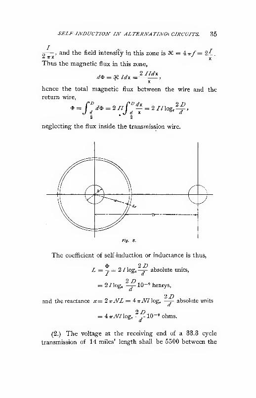
SELF-INDUCTION IN ALTERNATING^ CIRCUITS. 35
/
I TTX'2— ,. and the field intensity in this zone is X = 4ir/= lL.
Thus the magnetic flux in this zone,
(/$ = ae idf. = >
X
hence the total magnetic flux between the wire and the
return wire,
$ = I d^ = 21/ I — = 2 7/ log,—;-
,
2 • 2
neglecting the flux inside the transmission wire.
Fig. 8.
The coefficient of self-induction or inductance is thus,
d$ '2D
L = — = 2 I \og^ —J- absolute units,
= 2 /log, ?^10-«henrys,
2Z»and the reactance x=2 itNL = iirJVl lege —j- absolute units
= 4TiWlog, -^10"" ohms.
(2.) The voltage at the receiving end of a 33.3 cycle
transmission of 14 miles' length shall be 5500 between the

36 ELECTRICAL ENGINEERING.
lines. The transmission consists of three wires, (No.
B. & 5. G) {d= .82 cm), 18" (45 cm.) apart, of resistivity p
= 1.8 X 10-".
a.) What is the resistance, the reactance, and the impedance
per Hne, and the voltage consumed thereby at 44 amperes flow-
ing over the Hne ?
3.) What is the generator voltage between lines at 44 am-
peres flowing into a non-inductive circuit ?
c.) What is the generator voltage between lines at 44 am-
peres flowing into a circuit of 45° lag ?
(/.) What is the generator voltage between lines at 44 am-
peres flowing into a circuit of 45° lead ?
Here, I = 14 miles = 14 X 1.6 x 10= = 2.23 x 10= cm.
a= .82 cm.
Hence section s = .628 cm^.
Z'=45J\r= 33.3 thus,
^ ^ . ,. / 1.8 X 10-= X 2.23 X 10«a.) Resistance per hne, r=p-= . _-,
= 7.60 ohms.2D
Reactance per line, x = iirJVllog^—j- X 10~'= 4 7r X 3.33
X 2.23 X 108 X log^ 110 X 10-» = 4.35 ohms.
The impedance per line z = y/r" + x^ = 8.76 ohms. Thus
if /= 44 amperes per line,
E.M.F. consumed by resistance, E^ = r/= 334 volts.
E.M.F. consumed by reactance, E^ = xl= 192 volts.
E.M.F. consumed by impedance, £g= zl= 385 volts.
3.) 5500 volts between lines at receiving circuit give
5500—T^ = 3170 volts between line and neutral or zero point
(Fig. 9), or per line, corresponding to a maximum voltage
of 3170 V2 = 4500 volts. 44 amperes effective per line
gives a maximum value of 44 V2 = 62 amperes.
Denoting the current by,
i = 62 sin <^

SELF-INDUCTION IN ALTERNATING CIRCUITS. 37
the voltage per line at the receiving end with non-inductive
load is ^ = 4500 sin ^.
The E.M.F. consumed by re-
sistance, in phase with the current,
of effective value 334, thus maxi-
mum value 334 V2 = 472, is,
e^ = 472 sin <ji.
The E.M.F. consumed by re-
actance, 90° ahead of the cur-
rent, of effective value 192, thus p,- g
maximum value 192 V2 = 272, is,
^2 = 272 cos <^.
Thus the total voltage required at the generator end of
the line is, per line,
e^ = e + ei + e^ = (4600 -|- 472) sin <^ -|- 272 cos <^
= 4972 sin <^ -|- 272 cos ^272
denoting .„„„ =,tan /3, we have,
. _ tanyg _ 272'"'^~ Vm^~4980-
1 4972cos B =
,= = „„-, •
VI -f- tan^ 134980
Hence, e^ = 4980 (sin <j) cos /3 + cos (j> sin )3)
= 4980 sin (<^ -f- ^8).
Thus fi is the lag of the current behind the E.M.F. at
the generator end of the line, = 3.2°, and 4980 the maximum4980
voltage per line at the generator end, thus E^ = —r=-
V2= 3520, the effective voltage per line, and 3520 V3= 6100
the effective voltage between the lines at the generator.
c.) If the current,
/ = 62 sin 4>
lags 45° behind the E.M.F. at the receiving end of the line,
this E.M.F. is expressed by
38 ELECTRICAL ENGINEERING.
e = 4500 sin (<^ + 45) = 3170 (sin <^ + cos <^),
that is, it leads the current by 45°, or is zero at <^ = — 45°.
The E.M.F. consumed by resistance and by reactance
being the same as in d), the generator voltage per line is,
e^ = e + ei + e^ = 3642 sin<f> + 3442 cos
<t>
B442denoting woTn — tan p, we have,
Ca = 6011 sin (0 + j8).
Thus j8, the angle of lag of the current behind the gen-
erator E.M.F., is 43°, and 5011 the maximum voltage, hence
3550 the effective voltage per line, and 3550 V3 = 6160
the effective voltage between lines at the generator.
d.) If the current
i = 62 sin ^
leads the E.M.F. by 45°, the E.M.F. at the receiving end is,
e = 4500 sin (<^ - 45)
= 3170 (sin ^ — cos <^).
Thus at the generator end
e^ = e + e^ + e^= 3642 sin <^ — 2898 cos <^
. 2898 „ . .
denotmg q^j^ = tan p, it is
^0 = 4654 sin (<^ - ^).
Thus j8, the angle of lead at the generator, = 39°, and4654 the maximum voltage, hence 3290 the effective voltage
per line and 5710 the effective voltage between lines at the
generator.
8. EFFECT OF ALTERNATING CURRENTS.
The effect or power consumed by alternating current
z = /„ sin <i>, of effective value /= -^, in a circuit of re-v2
sistance r and reactance x = 2 ttNL, is,
/ = ei

EFFECT OF ALTERNATING CURRENTS. 39
where e = zl^ sin (</> + u) is the impressed E.M.F. consisting
of the components,
i?i = rl^ sin </) the E.M.F. consumed by resistance,
and <?2 = xlf^ cos <^ the E.M.F. consumed by reactance,
and 2 = \jr^ + o? is the impedance, tan u = - the phase
angle of the circuit.
The effect is thus,
/ = zl^ sin <^ sin (<^ + a>)
2/2= —^ (cos 0) — cos (2 ^ + «)))
= z/^ (cos M — cos (2 <^ + o))).
Since the average cos (2 ^ + <o) = zero, the average
effect is
P — zl^ cos Q>
= rJ-" = E^I.
That is, the effect of the circuit is that consumed by the
resistance, and independent of the reactance.
Reactance or self-induction consumes no effect, and the
E.M.F. of self-induction is a wattless E.M.F., while the
E.M.F. of resistance is an energy E.M.F.
The wattless E.M.F. is in quadrature, the energy E.M.F.
in phase with the current.
In general, if <« = phase angle of circuit, / = current,
E = impressed E.M.F., consisting of two components, one
E^ = E cos <o, in phase with the current, the other, E^ = Esin u>, in quadrature with the current, the effect of the cir-
cuit is lEf^ = IE cos (0, and the E.M.F. in phase with the
current E^ = E, cos w is an energy E.M.F., the E.M.F. in
quadrature with the current E^ = E sin o>, a wattless E.M.F.
Thus we have to distinguish energy E.M.F. and wattless
E.M.F., or energy component of E.M.F., in phase with the
current, and wattless component of E.M.F., in quadrature
with the current.
Any E.M.F. can be considered as consisting of two com-
ponents, one in phase with the current or energy E.M.F. e^.

40 ELECTRICAL ENGINEERING.
and one in quadrature with the current or wattless E.M.F.
e^. The sum of instantaneous values of the two components
is the total E.M.F.e = e^-\- ifj.
If E, Ej, E^ are the respective effective values, we have,
E = VA' + £^, since
£^=: £ cos u>
E^ = E sin s)
where m = phase angle between current and E.M.F.
Analogously, a current / passing through a circuit of
impressed E.M.F. E with phase angle <« can be considered
as consisting of two component currents,
Ix = I cos <D, the energy current or energy component of cur-
rent, and,
-^ = / sin (0, the wattless current or wattless component of
current.
The sum of instantaneous values of energy and of watt-
less currents equals the instantaneous value of total current,
4 + 4 = ^
while their effective values have the relation,
T=^ V/i^ -I- LJ.
Thus an alternating current can be resolved in two com-
ponents, energy current, in phase, and wattless current, in
quadrature, with the E.M.F.
An alternating E.M.F. can be resolved in two compo-
nents, energy E.M.F., in phase, and wattless E.M.F., in
quadrature, with the current.
The effect of the circuit is the current times the E.M.F.
times the cosine of the phase angle, or is the energy current
times the total E.M.F., or the energy E.M.F. times the
total current.

POLAR CO-ORDINATES. 41
EXAMPLES.
(1.) What is the effect received over the transmission line
in section 7, example 2, the effect lost in the line, the effect
put into the line, and the efficiency of transmission with non-
inductive load, 45° lag and 45° lead ?
The effect received per line at noninductive load is P= EI= 3170 X 44 = 137 K.W.
On load of 45° phase displacement, P = E I cos 45°
= 97 K.W.The effect lost per line P^^PR = A4? X 7.6 = 14.7
K.W.
Thus the input into the line P^= P -^ P^ = 151.7 K.W.at noninductive load,
and = 111.7 K.W. at load of 45° phase displacement.
The efficiency is with noninductive load,
P 14 7
With load of 45° phase displacement,
P 14 7
^ = i-m:7 = «^-«%-
The total output is 3 Z' = 411 K.W. and 291 K.W.,
respectively.
The total input 3/'„ = 451.1 K.W. and 335.1 K.W.,
respectively.
9. POLAR CO-ORDINATES.
In polar co-ordinates, alternating waves are represented,
with the instantaneous values as radii vectors, and the time
as angle, counting left-handed or counter clockwise, and one
revolution or 360° representing one complete period.
The sine wave of alternating current z = /„ sin <^ is
represented by a circle (Fig. 10) with the vertical axis as
diameter, equal in length O I„ to the maximum value /„, and
shown as heavy drawn circle.

42 ELECTRICAL ENGINEERING.
The E.M.F. consumed by self-induction, e^ = x I^ cos <^,
is represented by a circle with diameter OE^ in horizontal
direction to the right, and equal in length to the maximum
value, xl^
Analogously, the counter E.M.F. of self-induction E^_ is
represented by a circle O E^, in Fig. 10, the E.M.F. con-
sumed by resistance r by circle OE^ of a diameter = E^
— r/„, the counter E.M.F. of resistance E^ by circle 0E(.
]

POLAR CO-ORDINATES. 43
is represented by circle (9 ^ of a diameter equal in length
to E, and leading the diameter of the current circle by
angle u>. This circle passes through the points E.^ and E^.
An alternating wave is determined by the length and
direction of the diameter of its polar circle. The length is
the maximum value or intensity of the wave, the direction
the phase of the maximum value, generally called the phase
of the wave.
Usually alternating waves are represented in polar co-
ordinates by mere vectors, the diameters of their polar
circles, and the circles omitted, as in Fig. 11.
Fig. 11.
Two E.M.F.'s, ^1 and c^, acting in the same circuit, give a
resultant E.M.F. e equal to the sum of their instantaneous
values. In polar co-ordinates e^ and e^ are represented in
intensity and in phase by two vectors, OE^ and OE^, Fig.
12. The instantaneous values in any direction OX are the
projections ^, C^^ of OE^ and OE^ upon this direction.
Since the sum of the projections of the sides of a paral-
lelogram is equal to the projection of the diagonal, the sum
of the projections Oe^ and 07^ equals the projection Oe of

44 ELECTRICAL ENGINEERING.
OE, the diagonal of the parallelogram with OE^ and O E^
as sides, and E i?, thus the diameter of the circle of re-
sultant E.M.F.
That is,
In polar co-ordinates alternating sine waves of E.M.F.,
current, etc., are combined and resolved by the parallelo-
gram or polygon of sine waves.
Since the effective values are proportional to the maxi-
mum values, the former are generally used as the length of
vector of the alternating wave. In this case the instantane-
Fig. 12.
ous values are given by a circle with V2 times the vector as
diameter.
As phase of the first quantity considered, as in the above
instance the current, any direction can be chosen. Thefurther quantities are determined thereby in direction or
phase.
In polar co-ordinates, as phase of the current, etc., is
here and in the following xmderstood the time or the angle
of its vector, that is, the time of its maximum value, and a
current of phase zero would thus be denoted analytically by
i = /„ cos ^.

POLAR CO-ORDINATES. 45
The zero vector A \s generally chosen for the mostfrequently used quantity or reference quantity, as for the
current, if a number of E.M.F.'s are considered in a circuit
of the same current, or for the E.M.F., if a number of cur-
rents are produced by the same E.M.F., or for the induced
E.M.F. in induction apparatus, as transformers and induc-
tion motors, or for the counter E.M.F. in synchronous
apparatus, etc.
With the current as zero vector, all horizontal compo-
nents of E.M.F. are energy E.M.F.'s, all vertical components
are wattless E.M.F.'s.
With the E.M.F. as zero vector, all horizontal components
of current are energy currents, all vertical components of
currents are wattless currents.
By measurement from the polar diagram numerical values
can hardly ever be derived with sufificient accuracy, since
the magnitude of the different quantities entering the same
diagraip is usually by far too different, and the polar diagram
is therefore useful only as basis for trigonometrical or other
calculation, and to give an insight into the mutual relation
of the different quantities, and even then great care has to
be taken to distinguish between the two equal but opposite
vectors: counter E.M.F. and E.M.F. consumed by the
counter E.M.F., as explained before.
EXAMPLES.
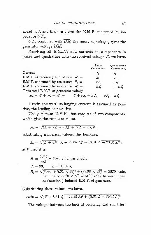
In a three-phase long distance transmission, the voltage
between lines at the receiving end shall be 5000 at no load,
5500 at full load of 44 amperes energy current, and propor-
tional at intermediary loads ; that is, 5250 at \ load, etc.
At J load the current shall be in phase with the E.M.F. at
the receiving end. The generator exxitation and thus the
(nominal) induced E.M.F. of the generator shall be main-
tained constant at all loads. The line has the resistance
^j^= 7.6 ohms and the reactance x^ = 4.35 ohms per wire,

46 ELECTRICAL ENGINEERING.
the generator in Y connection per circuit the resistance
^2 = .71, and the (synchronous) reactance x^ = 25 ohms.
What must be the current and its phase relation at no load,
i load, i load, | load, and full load, and what will be the
terminal voltage of the generator under these conditions .'
The total resistance of the circuit is, r=r^ + r2 = 8.31
ohms. The total reactance, x = Xj^+ ^2= 29.35 ohms.
4fIS
Fig. 13.
Let, in the polar diagram. Fig. IB or 14:, OE = £ repre-
sent the voltage at the recei\'ing end of the line, 01^ = /j
the energy current corresponding to the load, in phase with
Fig. 14.
OE, and 01^ = 1^ the wattless current in quadrature with
OE, shown leading in Fig. 13, lagging in Fig. 14.
We then have, total current 1=01.Thus E.M.F. consumed by resistance, OE.^ = rl in phase
with /. E.M.F. consumed by reactance, OE^ = xI, 90°
A
Wattless current, I^ =

HYSTEJiESIS AND EFFECTIVE RESISTANCE. 49
by this flux, or counter E.M.F. of self-induction, 'O^'" = E"= xl, lags 90° behind the current. The E.M.F. consumedby self-induction or impressed E.M.F. 'OE" = E" =xl is
thus 90° ahead of the current.
Inversely, if the E.M.F. 'OE" = E" is impressed upon a
circuit of reactance x =1 n-NL and of negligible resistance,
E"the current 01=1= — lags 90° behind the impressed
E.M.F.
This current is called the ex-
citing or magnetizing current of
the magnetic circuit, and is watt-
less.
If the magnetic circuit contains
iron or other magnetic material,
energy is consumed in the mag-
netic circudt by a frictional resist-
ance of the material against a
change of magnetism, which is
called molecular magnetic friction.
If the alternating current is the
only available source of energy in
the magnetic circuit, the expendi-
ture of energy by molecular mag-
netic friction appears as a lag of
the magnetism behind the M.M.F.
of the current, that is, as magnetic
hysteresis, and can be measured
thereby.
Magnetic hysteresis is, how-
ever, a distinctly different phenomenon from molecular mag-
netic friction, and can be more or less .eliminated, as for in-
stance by mechanical vibration, or can be increased, without
changing the molecular magnetic friction.
In consequence of magnetic hysteresis, if an alternating
E.M.F. OE" = E" is impressed upon a circuit of negligible
*->-i
Fig. 15.

50 ELECTRICAL ENGINEERING.
resistance, the exciting current, or current producing the
magnetism, in this circuit is not a wattless current, or current
of 90° lag, as in Fig. 15, but lags less than 90°, by an angle
90 — a, as shown by C/= /in Fig. 16.
Since the magnetism (9* = *
is in quadrature with the E.M.F.
E" due to it, angle a is the phase
difference between the magnetism
and the M.M.F., or the lead of the"« '*
M.M.F., that is, the exciting cur-
rent, before the magnetism. It is called the angle of
hysteretic lead.
In this case the exciting current 01= I can be
resolved in two components, the magnetizing cuirent
\" 01^ = /j in phase with the magnetism O^ = *, that
is, in quadrature with the E.M.F. OE" = E", and
thus wattless, and the magnetic energy ciirrent or hysteresis
current 01.^ = /j, in phase with the E.M.F. OE" = E", or
in auadrature with the magnetism 0^ = 9.
Magnetizing current and magnetic energy current are
the two components of the exciting current.
If the alternating circuit contains besides the reactance
X = 1-kNL, a resistance r, the E.M.F. OE" = E" in the
preceding Fig. 15 and Fig. 16 is not the impressed E.M.F.,
but the E.M.F. consumed by self-induction or reactance,
and has to be combined. Figs. 17 and 18, with the E.M.F.
consumed by the resistance, OE' = E' = Ir, to get the im-
pressed E.M.F. ~0E = E.
Due to the hysteretic lead a, the lag of the current is
less in Figs. 16 and 18, a circuit expending energy in mole-
cular magnetic friction, than in Figs. 15 and 17, a hysteresis-
less circuit.
As seen in Fig. 18, in a circuit whose ohmic resistance
is not negligible, the magnetic energy current and the mag-
netizing current are not in phase and in quadrature respec-
tively with the impressed E.M.F., but with the counter

HYSTERESIS AND EFFECTIVE RESISTANCE. 51
E.M.F. of self-induction or E.M.F. consumed by self-induc-
tion.
Thus the magnetizing current is not quite wattless, as
obvious, since energy is consumed by this current in the
ohmic resistance of the circuit.
Resolving, in Fig. 19, the impressed E.M.F. OE = E \n
two components, OE^ = E.^ in phase, and E^ = E^ in
quadrature with the current 01=1, the energy E.M.F.
^^j = El is greater than E' = Ir, and the wattless E.M.F.
'OE, = E^ less than E" = Ix.

62 ELECTRICAL ENGINEERINd
, E. energy E.M.F. . ,, , , „The value r = -f = ^ ^ ,
— is called the effectiveI total current
, E„ wattless E.M.F. . „ ,
resistance, and the value x = ^r = ^ ^ ,—- is called
' / total current
the apparent or effective reacta^ice of the circuit.
Due to the loss of energy by hysteresis (eddy currents,
etc.), the effective resistance differs from, and is greater
than, the ohmic resistance, and the apparent reactance is less
than the true or self-inductive reactance.
The loss of energy by molecular magnetic friction per
cm' and cycle of magnetism is approximately,
where (B = the magnetic induction, in lines of magnetic
force per cm',
W= energy, in absolute units or ergs per cycle (= 10~'
watt seconds or joules), and ?; is called the coefficient of
hysteresis.
In soft annealed sheet iron or sheet steel, -q varies from
1.25 X 10~° to 4 X 10"', and can in average, for good m^-
tQrial, be assumed as 2.5 X 10~*.
The loss of power in volume V, at magnetic density (B
and frequency N, is thus,
P= VNr,(S>^^ X 10-' watts
and, if /= exciting current, the hysteretic effective resist-
ance is,
P ffii"/' = ^= ri\^,io-'^.
If the magnetic induction (S> is proportional to the cur-
rent /, it is,
' that is, the effective hysteretic resistance is inversely pro-
portional to the .4 power of the current, and directly pro-
portional to the frequency.

BVSTEJiESIS AND EFFECTIVE RESISTANCE. 53
Besides hysteresis, eddy- or Foucault currents contrib-
ute to the effective resistance.
Since at constant frequency the Foucault currents are
proportional to the magnetism inducing them, and thus
approximately proportional to the current, the loss of power
by P'oucault currents is proportional to the square of the
current, the same as the ohmic loss, that is, the effective
resistance due to Foucault currents is approximately con-
stant at constant frequency, while that of hysteresis de-
creases slowly with the current.
Since the Foucault currents are proportional to the fre-
quency, their effective resistance varies with the square of
the frequency, while that of hysteresis varies only propor-
tionally to the frequency.
The total effective resistance of an alternating current
circuit increases with the frequency, but is approximately
constant, within a limited range, at constant frequency, de-
creasing somewhat with the increase of magnetism.
EXAMPLES.
A reactive coil shall give 100 volts E.M.F. of self-
induction at 10 amperes and 60 cycles. The electric circuit
consists of 200 turns (No. 8 B. & S. G.) (s = .013 sq. in.) of
16" mean length of turn. The magnetic circuit has a sec-
tion of 6 sq. in. and a mean length of 18", of iron of hyster-
esis coefiScient i; = 2.5 X 10~^ An air gap is interposed
in the magnetic circuit, of a section of 10 sq. in. (allowing
for spread), to get the desired reactance.
How long must the air gap be, and what is the resist-
ance, the reactance, the effective resistance, the effective
impedance, and the power factor of the reactive coil .?
200 turns of 16" length and .013 sq, in. section at
resistivity of copper of 1.8 X 10~° have the resistance,
1.8 X 10-" X 200x16 ,__ ,
"^ =.013 X 2.54
= -1^^ "^'"^
where the factor 2.54 reduces from inches to cm.

54 ELECTRICAL ENGINEERING.
E = 100 volts induced,
iV'= 60 cycles, and
n — 200 turns,
the maximum magnetic flux is given hy E = ^A^.Nn^
or, 100 = 4.44 x .6 X 200 *,
as, ^ = .1^8 ml.
This gives in an air gap of 10 sq. in. a maximum density
(B = 18,800 lines per sq. in. or 2920 lines per cm^.
Ten amperes 'in 200 turns give 2000 ampere turns ef-
fective or SF = 2830 ampere turns maximum.
Neglecting the ampere turns required by the iron part
of the magnetic circuit, 2830 ampere turns have to be con-
sumed by the air gap of density, (B = 2920.
Since,
®-ir/'
the length of the air gap has to be
, 4 JF 4 X 2830
10 (B 10 X 2920= 1.22 cm, or .48"
At 6 sq. in. section and 18" mean length the volume of
iro;i is 180 cu. in. or 1770 cm'''.
The density in the iron <S,-^= '-— = 31330, lines per
sq. in., or 4850 lines per cm^.
At hysteresis coefficient 17 = 2.5x10^^, and density <\ =4850, the loss of energy per cycle and cm^ is
= 2.5 X 10⁻⁵ ^ 4850"= 2220 ergs,
and the hysteresis loss at iV= 60 cycles and the volume V= 1770 is thus,
P = 60 X 1770 X 2220 ergs per sec.
= 23.5 watts,

CAPACITY AND CONDENSERS. 55
which at 10 amperes represent an effective hysteretic
resistance,
23.5102"'' 2 — -tt::: — -235 ohms.
Hence the total effective resistance of the reactive coil is,
r =r^-\- r^ = .175 + .235 = .41 ohms.
The reactance is,
X = -' = 10 ohms.
Thus the impedance,
z = 10.01 ohms,
and the power factor,
/ =J= 4.1%.
The total volt-amperes of the reactive coil are,
Pz = 1001.
The loss of power :
Pr = 41.
11. CAPACITY AND CONDENSERS.
The charge of an electric condenser is proportional to
the impressed voltage and to its capacity.
A condenser is called of unit capacity if unit current
flowing into it during one second produces unit difference
of potential at its terminals.
The practical unit of capacity is that of a condenser in
which one ampere flowing during one second produces one
volt difference of potential.
The practical unit of capacity equals 10~' absolute units.
It is called a farad.
One farad is an extremely large capacity, and one mil-
lionth of one farad is commonly used, and called one micro-
farad, mf.

66 ELECTRICAL ENGINEERING.
If an alternating E.M.F. is impressed upon a conden-
ser, the charge of the condenser varies proportionally to the
E.M.F., and thus current flows into the condenser during
rising, out of the condenser during decreasing E.M.F., as
shown in Fig. 20.
That is, the current consumed by the condenser leads
the impressed E.M.F. by 90°, or a quarter of a period.
Fig, 20.
li N = frequency, E = effective alternating E.M.F. im-
pressed upon a cdndenser of C. mf capacity, the condenser
is charged and discharged twice during each cycle, and the
time of one complete charge or discharge is thus, ——
Since £ V2 is the maximum voltage impressed upon
the condenser, an average of CE V2 10"" amperes would
have to flow during one second to charge the condenser to
this voltage, and to charge it during —- seconds, thus an
average current of 4 NCE V2 10"" amperes is required.
effective current ir
Since = -^average current 2 V2
the effective current I=1tsNCE 10~^ that is, at an impressed
E.M.F of ^ effective volts and frequency N, a condenser of
C mf capacity consumes a current of,
7= 2 iriVC-fi 10-° amperes effective,
which current leads the terminal voltage by 90° or a quarter
period, or inversely.
CAPACITY AND CONDENSERS. 57
2,rNC ~ "
The value Xo = ,,„ is called the capacity reactance of
the condenser.
Due to the energy loss in the condenser by dielectric
hysteresis, the current leads the E.M.F. by somewhat less
than 90°, and can be resolved into a wattless charging cur-
rent and a dielectric hysteresis current, which latter, how-
ever, is so small as to be generally negligible.
The capacity of one wire of a transmission line is,
^ 1.11 X 10-° x/ ^C= 2^— ""f-
21og._
where
d = diameter of wire, cni,
D = distance of wire from return wire, cm,
/ = length of wire, cm,
1.11 X 10^°= reduction coefficient from electrostatic units to mf.
The logarithm is the natural logarithm, thus in commonlogarithm, since log, a = 2.303 logjo^, the capacity is,
^ .25 X 10-«x/ ^C= 2:^mf.logio-
d
The derivation of this equation must be omitted here.
The charging current of a line wire is thus,
/=2,r7VC£'10-^where
N= the frequency,
E = the difference of potential, effective, between the line
and the neutral {E = \ line voltage in a single-phase,
or four-wire quarterphase system, —p line voltage, or
K voltage, in a three-phase system).

58 ELECTRICAL ENGINEERING.
EXAMPLES.
In the transmission line discussed in the examples in
§§ 7, 8, and 9, what is the charging current of the line at
• 6000 volts between lines and 33.3 cycles.? How many
volt amperes does it represent, and what percentage of the full
load current of 44 amperes is it .'
The length of the line is, per wire, / = 2.23 x 10^ cm.
The distance between wires, Z? = 46 cr.i.
The diameter of transmission wire, d = .82 cm.
Thus, the capacity, per wire,
.25 X 10-V „^ .C=- 2^ = .27mf.
log,„-^
The frequency is, iV= 33.3,
The voltage between lines, 6000.
Thus per line, or between line and neutral point,
^ = ^^=3460.V3
Hence the charging current per line,
/o=2TAr£10-'>= .195 amperes,
or .443% of fulHoad current,
that is, negligible in its influence on the transmission
voltage.
The volt-ampere input of the transmission is,
3/(^ = 2000
= 2.(iKVA.
12. IMPEDANCE OF TRANSMISSION LINES.
Let r = resistance,
X = 2 irNL = reactance of a transmission line,
£(,= alternating E.M.F. impressed upon the line,
/= current flowing over the line,
£ = E.M.F. at receiving end of the line, and
u = angle of lag of current / behind E.M.F. £.

IMPEDANCE OF TRANSMISSION LINES. 59
^ifejUw i

60 ELECTRICAL ENGINEERING.
That is, the voltage E^ required at the sending end of a
line of resistance r and reactance x, delivering current / at
voltage E, and the voltage drop in the line, do not depend
upon current and hne constants only, but depend also upon
the angle of phase displacement of the current delivered
over the line.
If (0 = 0, that is noninductive circuit,
,=V^{E + Izf - ^Elzsax^^,
that is less than E+Iz, and thus the line drop less than Iz.
If <a=a, E„ is a maximum, =^+/^' and the line drop is
the impedance voltage.
Fig. 22.
With decreasing u, E^ decreases, and becomes = E;
that is, no drop of voltage takes place in the line at a certain
negative value of a, which depends not only on z and a, but
V on E and /. Beyond this value of o>, E becomes smaller

IMPEDANCE OF TRANSMISSION LINES. 61
than E ; that is, a rise of voltage takes place in the line, due
to its reactance. This can be seen best graphically.
For the same E.M.F. E received, but different phase
angles u, all vectors OE lie on a circle e with as center.
Fig. 22. Vector OE^ is constant for a given line and given
current /.
Fig. 23.
Since EgE^ = OE = constant, E^ lies on a circle e„ with
Eg as center and OE = E zs radius.
To construct the diagram for angle a),_OE is drawn
under angle w with 01, and EE^ parallel to OE^.
The distance E^E^ between the two circles on vector
OEg is the drop of voltage (or rise of voltage) in the line^
As seen in Fig. 23, E^ is maximum in the direction OE^

62 ELECTRICAL ENGINEERING.
as OE^, that is for o)=a, and is less for greater as well,
OE" as smaller angles w. It is =i5' in the direction OEI''
in which case <u<C, and minimum in the direction OE^^ .
The values of E corresponding to the generator voltages
El, E;', El", El'" are shown by the points E' E" E'" E""
respectively. The voltages El' and El"' correspond to a
wattless receiver circuit E" and E'"' . For noninductive
receiver circuit OE the generator voltage is 0±l^
That is, in an inductive transmission line the drop of
voltage is maximum and equal to Is, if the phr.se r.ngle k of
the receiving circuit equals the phase angle a of the line.
The drop of voltage in the "line decreases with increasing
difference between the phase angles of line and receiving
circuit. It becomes zero if the phase angle of the receiving
circuit reaches a certain negative value (leading current).
In this case no drop of voltage takes place in the line. If
the current in the receiving circuit leads more than this
value a rise of voltage takes place in the line. Thus by
varying phase angle <o of the receiving circuit, the drop of
voltage in a transmission line with current I can be made
anything between Jz and a certain negative value. Or in-
versely the same drop of voltage can be produced for differ-
ent values of the current / by varying the phase angle.
Thus, if means are provided to vary the phase angle of
the receiving circuit, by producing lagging and leading
currents at will (as can be done by synchronous motors or
converters) the voltage at the receiving circuit can be main-
tained constant within a certain range irrespective of the
load and generator voltage.
In Fig. 24 let OE=E the receiving voltage, / the energy
current flowing over the line, thus OE^=E^=Iz the E.M.F.
consumed by the impedance of the energy current consist-
ing of the E.M.F. consumed by resistance OE,^ and the
E.M.F. consumed by reactance OE^.
Wattless currents are represented in the diagram in the
direction OA when lagging and OB when leading. The

IMPEDANCE OF TRANSMISSION LINES. 63
E.M.F. consumed by impedance of these wattless currents is
thus in the direction e^ at right angles to OE^. Combining
OE^ and OE gives the E.M.F. OE^, which would be required
for noninductive load. If E^ is the generator voltage, E^ lies
on a circle e^ with OE^ as radius. Thus drawing E^E^ par-
.'"E,
allel to e^ gives OE^ the generator voltage, OE^=E^E^
the E.M.F. consumed by impedance of the wattless current,
and proportional thereto 01'— I' the wattless current re-
quired to give at generator voltage E^ and energy current /,
the receiver voltage E. This wattless current /' lags be-
hind E^ by less than 90 and more than zero degrees.
In calculating numerical values, wz can either proceed
trigonometrically as in the preceding, or algebraically by

64 ELECTRICAL ENGINEERING.
resolving all sine waves in two rectangular components, for
instance, a horizontal and vertical component, in the same
way as in mechanics when combining forces.
Let the horizontal components be counted positive
towards the right, negative towards the left, and the verti-
cal component positive upwards, negative downwards.
Assuming the receiving voltage as zero line or positive
horizontal line, the energy current T is the horizontal, the
wattless current /' the vertical component of current. TheE.M.F. consumed by resistance is horizontal component with
the energy current I and vertical component with the watt-
less current /', and inversely the E.M.F. consumed byreactance.
We have thus, as seen from Fig. 24.
Receiver voltage E,
Energy current, /,
Wattless current, /',
E.M.F. consumed by resistance r
of energy current, Ir,
E.M.F. consumed by resistance r
of wattless current I'r,
E.M.F. consumed by reactance xof energy current, Ix,
E.M.F. consumed by reactance xof wattless current, I'x.
Thus, total E.M.F. required or im-
pressed E.M.F., Ef^, 1
hence, conbined.
horizdn'talComponent.

IMPEDANCE OF TRANSMISSION LINES. 65
The lag of the total current in the receiver circuit behind
the receiver voltage is
I'tan 0) = — •
The lead of the generator voltage ahead of the receiver
voltage is
vertical component of Entan Q = =
—
-. —
^
horizonal component of En
_ ±/'r — Ix~ E + Ir ± I'
x'
and the lag of the total current behind the generator volt-
age is
<Dq = O) + 6.
As seen, by resolving into rectangular components the
phase angles are directly determined from these components.
The resistance voltage is the same component as the
current to which it refers.
The reactance voltage is a component 90° ahead of the
current.
The same investigation as made here on long-distance
transmission applies also to distribution lines, reactive coils,
transformers, or any other apparatus containing resistance
and reactance inserted in series into an alternating current
circuit.
EXAMPLES.
1. In an induction motor, at 2000 volts impressed upon
its terminals, the current and the power factor, that is, the
cosine of the angle of lag, as function of the output, are as
given in Fig. 25.
The induction motor is supplied over a line of resistance
r=2.0 and reactance jr=4.0.
a) How must the generator voltage r,, be varied to main,
tain constant voltage ^= 2000 at the motor terminals, and
b) At constant generator voltage ^o=2300, how will the
voltage at the motor terminals vary.

66 ELECTRICAL ENGINEERING.
We have,
e. = \J{e + izf - 4 eiz sin^ -
z = \lr' -\- x" = 4.472
X
e = 2000.
= 63.4°.tan a^ - ^ 2.r
cos 0) = power factor,
and i taken from Fig. 25 and substituted, gives a) the values
of ^„ for ^= 2000, recorded on attached table, and plotted in
Fig. 25.

IMPEDANCE OF TRAXSMISSION LINES. 67
The values of e', i', P' are recorded in the second part
of attached table under b) and plotted on Fig. 26.
10 20 30 m 70 so 90 100 110 120 130 140
Fig. 26.
a)

68 ELECTRICAL ENGINEERING.
2.) Over a line of resistance r= 2.0 and reactance ;ir=
6.0, power is supplied to a receiving circuit at constant volt-
age of ^= 2000. How must the voltage at the beginning of
the line, or generator voltage, e^ be varied, if at no load the

ALTERNATING CURRENT TRANSFORMER. 69
hence, substituting the value of i^,
e^ = V(2120 - A i^f + (40 - 6.8 i^^
= V4,496,000 + 46.4 i^ - 2240 i^.
Substituting successive numerical values for i^, gives the
values recorded on attached table, and plotted in Fig. 27.
iy

70 ELECTRICAL ENGINEERING.
and in primary circuit, proportional with each other by the
Eratio of turns, Ei=—^- •
a
Let ^= secondary terminal voltage, /i= secondary cur-
rent, o)i=lag of current I^ behind terminal voltage E (where
<0i < denotes leading current).
Denoting then in Fig. 28 by a vector OE=E the sec-
ondary terminal voltage, OT.^=I^ is the secondary current
lagging by angle EOI=<o^.
Fig. 28.
The E.M.F. consumed by the secondary resistance 7\ is
OEl=El=I^\ in phase with I^.
The E.M.F. consumed by the secondary reactance x^ is
0E[' =El'= I^x^, 90° ahead of Z^. Thus the E.M.F. con-
sumed by the secondary impedance z.^= ^i'^-\- x^ is the re-
sultant of OE^ and OE^', or OE"'=E"'=I^z^.
OE ^"' combined with the terminal voltage OE=E gives
the secondary induced E.M.F. OE^=E^.
Proportional thereto by the ratio of turns and in phase
therewith is the E.M.F. induced in the primary OEi=EiE
where E=—i.
a
To induce E.M.F. E.^ and Ei, the magnetic flux C*=* is
required, 90° ahead of OE.^ and OE^. To produce flux * the

ALTERNATING CURRENT TRANSFORMER. 71
M.M.F. of SF ampere turns is required, as .determined from
the dimensions of the magnetic circuit, and thus the primary
current I^, represented by vector 01^, leading C4> by angle
a, the angle of hysteretic advance of phase.
Since the total M.M.F. of the transformer is given by
the primary exciting current /„„, corresponding to the sec-
ondary current /^ a component of primary current /', which
may be called the primary load current, flows opposite thereto
and of the same M.M.F., that is, of the intensity V—al^, thus
represented by vector 01'=r=alyQI^, the primary exciting current, and the primary load
current 01', or component of primary current corresponding
to the secondary current, combined, give the total primary
current 01^=1^.
The E.M.F. consumed by resistance in the primary is
OEl=El=I^\ in phase with /„.
The E.M.F. consumed by the primary reactance is OE^'
= E;'^T,x„ godhead of 01,. _6E^ and OE^' combined give OE^", the E.M.F. con-
sumed by the primary impedance.
Equal and opposite to the primary induced E.M.F. OEi
is the component of primary E.M.F. consumed thereby OE'.
OE' combined with OE," gives OE,=E,, the primary
impressed E.M.F., and angle «)o= -^o ^'4 ^he phase angle cf
the primary circuit.
Figs. 29, 30, and 31 give the polar diagrams for w^= -Li>°
or lagging current, a)^=zero or noninductive circuit, and u>^=— 45° or leading current.
As seen, the primary impressed E.M.F. .£'0 required to
produce the same secondary terminal voltage E at the same
current /^ is larger with lagging cr inductive, smaller with
leading current than on a noninductive secondary circuit, or
inversely at the same secondary current /j the secondary
terminal voltage E with lagging current is less, and with
leading current more than with noninductive secondary
circuit, at the same primary impressed E.M.F. £"„.

72 ELECTRICAL ENGINEERING.
The calculation of numerical values is not practicable by
measurement from the diagram, since the magnitudes of
the different quantities are too different. E( : E" : E^: E^
being frequently in the proportion 1 : 10 : 100 : 2000.
Fig. 29.
Trigonometrically, the calculation is thus :
In triangle OEE^, Fig. 28, we have,
writing,
tan <^i= —
,
also.
hence,
0£^' = 0£ + EE^ - 2 OEEE^ cos OEE^,
EE^ = I-^z-^
^ OE£^= 180 - <^i + (Oi;
E^- =£^ + /iV + 2 E/^z^ cos (<^i- 0,1).
This gives the secondary induced E.M.F"., E^, and there-
from the primary induced E.M.F.

ALTERNATING CURRENT TRANSFORMER. 73
In triangle EOE^, we have,
sin £^0E ~ smE^EO = EE^ h- E^O;
thus, writing
We have.
sin ^1 H- sin {<j>^ — w^ = I^z -=- ^j,
«g. 30.
Fig. 31.
therefrom we get
t A and 2^ ^jO/i = o) = 0)1 + A,
the phase displacement between secondary current and sec-
ondary induced E.M.F.
In triangle, OI^T^, we have,«
OI,' =0T^'+i^o - 2 OT^J^, cos OI^I„

74 ELECTRICAL ENGINEERING.
since
ii:^,O<^ = 90",
^ 0/„o/o=90-a,-a,and
OI^ = -^ = exciting current,
calculated from the dimensions of the magnetic circuit.
Thus,
>^o'= ^' + ""A" + 2 a/j/oo sin (o) + a),
the primary current.
In triangle OIq /„, we have
sin /oo07o -H sin 04,/o = IJ^^ OI^,
writing
this becomessin ^0 -i- sin (co + a) = a/j + /(,
;
therefrom we get /8„, and thus
^£'0/^ = 6^ = 90 -a- ^0-
In triangle 6^^' £„ we have
a£„' = 0£'''+ We^ - 2 OE'EE^ cos OE' E^,writing
tan <^o = — '
we have
^ C^'^o = 180 - ^0 + 8.
a
E'Eq = -^0'
^„^ =4V ^oV +^^ cos (</.„ - &),
thus,
the impressed E.M.F.
In triangle, OE' E^ is
sin E'OEa -^ sin 0£'£„ = £'£„ -=- 0^„;

ALTERNATIA'G CURRENr TRANSFORMER. 75
thus, writing,
we havesin y -f- sin (<^o
— S) = I^z^ -^ £o ;
herefrom we get ¥ y, and
^ 0)0 = e + y,
the phase displacement between primary current and im-
pressed E.M.F.
As seen, the trigonometric method of transformer calcu-
lation is rather complicated.
Somewhat simpler is the algebraic method, of resolving
into rectangular components.
Considering first the secondary circuit, of current /j lag-
ging behind the terminal voltage E by angle Uj.
The terminal voltage ^'has the components E cos <o^ in
phase, E sin w.^ in quadrature with and ahead of the current /j.
The E.M.F. consumed by resistance }\, I^i\, is in phase.
The E.M.F. consumed by reactance .r^, I^Xy, is in quad-
rature ahead of I^.
Thus the induced secondary E.M.F. has the components,
E cos 1 -f- fy^ in phase,
E sin (Dj -f- /jXi in quadrature ahead of the current /j,
and the total value :
^j = ^{E cos (Ui -H I-^r^^ + (£ sin eoi -|- I^x^'^,
and the phase angle of the secondary circuit is :
E sin (Oi -f- I-^x-^
tan (1) = E cos (Oi -\- /i^i
Resolving all quantities into components in phase and in
quadrature with the induced E.M.F. E^, or in horizontal and
in vertical components, chosing the magnetism or mutu?l
flux as vertical axis, and denoting the direction to the right
and upwards as positive, to the left and downwards as nega-
tive, we have,
-E

ALTERNATING CURRENT TRANSFORMER. 77
substituting this value., horizontal component of E^,
— + az^I^cos (<o — <^o) + %-^oo sin (a + </.o),
vertical component of Ef^,
azal^ sin (o) — <^o) + ^o^) cos (a + <^o)>
and, total primary impressed E.M.F.,
The total primary current is, by combining its two
components,
/g = V(a^ COS 0) + I^ sin a)" + (al^ sin <u + 7^ cos a)
Since the tangent of the phase angle is the ratio of
vertical component to horizontal component, we have,
primary E.M.F. phase,
azoli sin (w — </>„) + z^If^ cos (a + <^o) .
tan X = -g -_
'
— + az^Ii cos (<o— <^o) + -^o-^cosin (a — <^o)
a
primary current phase,
all sin <ii-{- Ifja cos atan ^ = —p
1 .y „ -—
>
a/jcos 0) + /oo sin a
and lag of primary current behind impressed E.M.F.,
EXAMPLES.
1). In a 20 K.W. transformer the ratio of turns is,
20 -^ 1, and 100 volts is produced at the secondary terminals
at full load. What is the primary current at full load, and

78 £L£CITRICAL ENGINEERING.
the regulation, that is, the rise of secondary voltage front
full load to no load, at constant primary voltage, and what
is this primary voltage ?
a), at noninductive secondary load,
b). with 60° lag in the external secondary circuit,
c). with 60° lead in the external secondary circuit.
The exciting current is .5 amperes, the hysteresis loss
600 watts, the primary resistance 2 ohms^, the primary
reactance 5 ohms, the secondary resistamce .0©4 ohms, the
secondary reactance .01 ohm.
600 watts at 2000 volts give .S amperes magnetic
energy current, hence V.6^— 3^ = .4 amperes magnetizing
current.
We have thus,
^0 = 2

RECTANGULAR CO-ORDINATES.
2. Magnetic flux as vertical axis,—79

80 ELECTRICAL ENGINEERING.
the trigonometric method or the method of rectangular
components is used.
The method of rectangular components, as explained in
the last paragraphs, is usually simpler and more convenient
than the trigonometric method.
In the method of rectangular components it is desirable
to disitinguish the two components from each other and from
the resultant or total value by their notation.
To distinguish the components from the resultant, small
letters are used for the components, capitals for the result-
ant. Thus in the transformer diagram of section 13 the
secondary current /j has the horizontal component ?j = — /j
cos <0y and the vertical component i^ = — /j sin Wj.
To distinguish horizontal and vertical components from
each other, either different types of letters can be used, or
indices, or a prefix or coefficient.
Different types of letters are inconvenient, indices dis-
tinguishing the components undesirable, since indices are
reserved for distinguishing different E.M.F.'s, currents, etc.,
from each other.
Thus the most convenient way is the addition of a pre-
fix or coefficient to one of the components, and as such the
letter/ is commonly used with the vertical component.
Thus the secondary curr^t in the transformer diagram
section 13 can be written,
«i-\- ji-i = Ix cos o)i+ jl-i sin oj.
This method offers the further advantage, that the two
components can be written side by side, with the plus sign
between them, since the addition of the prefix/ distinguishes
the value 7V2 ory/j sin ^ as vertical component from the hori-
zontal component \ or /^ cos <0j.•
A = h +Jh
thus means, \ consists of a horizontal component i^ and a
vertical component ^, and the plus sign signifies that i^ and
i^ are combined by the parellelogram of sine waves.

RECTANGULAR CO-ORDINATES. 81
The secondary induced E.M.F. of the transformer in
section 13, Fig. 28, is written in this manner, ^i = —^j,
that is, it has the horizontal component — ^^ and no vertical
component.
The primary induced E.M.F. is,
-Pi— '
a
and the E. M. F. consumed thereby
E'= +^-a
The secondary current is.
Wherei\ = I-i cos ft)i, 4 ^= /i sin coj
,
and the primary load current corresponding thereto is,
I'— — al^ = ai\ \- jai^.
The primary exciting current,
where h= I^ sin a is the magnetic energy current,^ =-^oo
cos ^ the wattless magnetizing current.
Thus the total primary current is,
/o= /'+ /oo = (ah + /') +7(^4+ g).
The E.M.F. consumed by primary resistance r,, is
'o/o = 'o Q^h + ^) +Jro (flh + g)-
The horizontal component of primary current {ai^-\-h)
gives as E.M.F. consumed by reactance x^ a negative vertical
component, denoted by —_/>„ («?i + Ii). The vertical com-
ponent of primary current/ {ai^ + g) gives as E.M.F. con-
sumed by reactance jr„ a positive hoizontal component,
denoted by x^ {ai^ + g).
Thus the total E.M.F. consumed by primary reactance
jr„is,
•*o {ch + g) —J'xo («'l + ^),

82 ELECTRICAL ENGINEERING.
and the total E.M.F. consumed by primary impedance is,
[ro iai^+ /4) + a:o {ai^ + ^)] +j [r„ (ai^ + g) — x,^ {a\ + h)\
Thus, to get from the current the E.M.F. consumed by
reactance x^^ to the horizontal component of current the
coefficient —j has to be added, in the vertical component the
coefficient / omitted. Or we can say,
The reactance is denoted by — jx^ for the horizontal,
and by — for the vertical component of current.
JOr other words,
If 1= i +ji' is a current, x the reactance of its circuit,
the E.M.F. consumed by the reactance is,
—jxi + xi' = xi'— jxi.
If instead of cmittingyin deriving the reactance E.M.F.
for the vertical component of current, we would add — y'also,
(as done when deriving the reactance E.M.F. for the hori-
zontal component of current) we get the reactance E.M.F.
—jxi — J^xi',
which gives the correct value —jxi + xi', if
that is, we can say.
In deriving the E.M.F. consumed by reactance, x.^, from
the current, we multiply the current by — jx, and substitute
y.= - 1-
—jx can thus be called the reactance in the representa-
tion in rectangular co-ordinates and
r — jx the impedance,
by defining, and substituting,
y===-i.
The primary impedance voltage of the transformer in
the preceding could thus be derived directly by multiplying
the current,
/o = iaH+ K) +j{aii + g),

RECTANGULAR CO-ORDINATES. 8S
with the impedance
^0 ^ 'o J^fi'
This gives
=''o
{aiy + K) +jr„ (ai^ + g) — jx^ {ai^ + h) —fx^ (az\ + g),
and substituting7^ = — 1,
Eo = [fo {ah + h)+ Xa {ai^ + g)} +j [r„ {ah + g) — x^ {ai^ + K)\,
and the total primary impressed E.M.F. is thus,
-£0 = -£' +-^o
-^ = ro(a?i + /z) + a:o(a/2 -^ g) +J raip-h + S)— x^{ai.^+h)
Such an expression in rectangular co-ordinates as,
represents not only the current strength but also its phase.
It means, in Fig. 32, that,
the total current 01 has the two
rectangular components, the hor-
izontal component / cos w = i,
and the vertical component
I sin o) = i'
.
Thus,
tan u) = Fig. 32.
that is, the tangent function of the phase angle is the verti-
cal component divided by the horizontal component, or the
term with prefix/ divided by the term without/
The total current intensity is obviously.
The capital letter / in the symbolic expression I=i-\-j i'
thus represents more than the / used in the preceding for
total current, etc., and gives not only the intensity but also
the phase. It is thus necessary to distinguish by the type
of the latter, the capital letters denoting the resultant cur-

84 ELECTRICAL ENGTNEERINL
rent in symbolic expression (that is, giving intensity and
phase) from the capital letters giving merely the intensity
regardless of phase.
That is,
denotes a current of intensity
and phase
tan to = — •
I
In the following, dotted italics will be used for the sym-
bolic expressions and plain italics for the absolute values of
alternating waves.
In the same way z = Vr^ + ;ir^ is denoted in symbolic
representation of its rectangular components by
Z = r — jx.
When using the symbolic expression of rectangular co-
ordinates it is necessary ultimately to reduce to commonexpressions.
Thus in the above discussed transformer the symbolic
expression of primary impressed E.M.F.
means that the primary impressed E.M.F. has the intensity,
^0= Y -^-\-u{ai^+h)+ Xa{ai^-\- g) + ra(ai^-\- g) — Xi,{a\^- hi
and the phase,
U ifh + g) — Xt, {m\ + h)tan <^o
=- + ^0 {ai^ + h) + Xg {ai^ + g)
This symbolism of rectangular components is the quick-
est and simplest method of dealing with alternating current
phenomena, and is in many more complicated cases the only

RECTANGULAR CO-ORDINATES. 85
method which can solve the problem at all, and thus the
reader should become fully familiar with this method.
EXAMPLES.
(1). In a 20 K.W. transformer the ratio of turns is 20 : 1,
and 100 volts are required at the secondary terminals at full
load. What is the primary current, the primary impressed
E.M.F., and the primary lag,
a) At noninductive load, wj = ;
b) With (Ui= 60° lag in the external secondary circuit;
c) With o>i= —60° lead in the external secondary circuit }
The exciting current is /oo' = .3 -\-Aj amperes, at ^=2000
volts impressed, or rather, primary induced E.M.F.
The primary impedance, Z', = 2 — bj ohms.
The secondary impedance, Zj = .004 — .01/ ohms.
We have, in symbolic expression, choosing the secondary
current /^ as real axis (see page 86).
(2). i?o= 2000 volts are impressed upon the primary cir-
cuit of a transformer of ratio of turns 20 : 1. The primary
impedance is, Z^ = 2 — bj, the secondary impedance, Z.^=
,004 — .Oiy, and the exciting current at / = 2000 volts
induced E.M.F. is ^, = .3 + Aj, thus the "primary admit-
tance," F = :^ = (.15 + 27) 10-=.e
What is the secondary current and secondary terminal
voltage, and the primary current, if the secondary circuit is
closed by,
a), resistance,
Z = r = .5 — noninductive circuit.
b). impedance,
Z = r —jx = .3 —AJ — inductive circuit.
c). impedance,
Z = r —Jx = .3 + AJ — anti-inductive circuit.
Let,
e = secondary induced E.M.F.,
assumed as real axis in symbolic expression (see page 86.)

86 ELECTRICAL ENGINEERING.

RECTANGULAR CO-ORDIXA TES. 87
++ I
^ * o >-i
'^~^
I 2>
;^ »I
-
3 '-' -+ g ^ g ^-Lc.>
_•>s^
'•>
V, 55 «; ^
SIS
I
ll"
N
'^
C0«
. '"^ + ^ 2 " S
''^
^ O —^ rFs ffsi m ^ri ,^ WW+ S, r- O I ^A
-^L H-. S °^ 1^ " 7^ -
^.-4^s|5|| r:§I O OS
CO>
» CDO
+ UO
^
1W5 WK>05
CO " - •. CO "C-^
LO .-^
«5Oi
11
iT
o o oi' r+
s
I^ 00 C<1O O Cip oc: I.
Vl %l %,
« II ^
,o 31 ^^ ^^
-r ^ M „ o '^-.S I
S, -N o i-hC^ ,•* I
- 1^+ oI
cc", ^ o 1
+
+ '^
c< COCD <M
t2 ,' =o <NO + (N fS - .
ICO o t^ r- , ^ 30
loco ES-'roooS00 ^C5 ^
(>4 CS ^ ^ ^
M iN)
-y
5 I
O 0}
r 3
II I
-_^.
'*!•II
o ^
CI.
s
II
•a
IS rt 3"C 13 "^3cogO O >u CJ -to oj irm w O
!+'
l^l-llJ'
II ^-ll '^•i^'
S S b " >
r-t r u H CJ
3 T3 .t; n, i
+
.W
a.
CO d13 S^ B" *:; <u •!:;
!>-, >i >, ° >pT3 O,
S g B S S |.i -C -C -C J3 -c ,><
a, Dh Ph H cu Wj3 >-"
H O
II
kj- • •
^.S 5 II S II
i ""I "S I "S
"-I § 3 § 3
^ .t: (u aj dj ^0) -S 03 P^ to si (
S II
O ifl tfl

88 ELECTRICAL ENGINEERING.
3). A transmission line of impedance Z = r —jx =20 — SOy feeds a noninductive receiving circuit. At the
receiving end, an apparatus is connected which produces
wattless lagging or leading currents at will (synchronous
machine) .12000 volts are impressed upon the line. Howmuch lagging and leading currents respectively must be
produced at the receiving end of the line, to get 10,000
volts,
a), at no load,
b). at 50 amperes energy current as load,
c). at 100 amperes energy current as load .?
Let
e = 10,000 = E.M.F. received at end of line.
4= energy current, 4 = wattless lagging current
;
thus,
/= i^ +Jh = total current in line.
The voltage at generator end of line is then,
^0= e + ZI
= (if + rz'i + xi^ -k-j{rh — xii)
= (10,000 + 20 !\ + 50 4) +y(20 4 - 50 i^),
or, reduced,
-Eo = V(^ + Hi + xz^f + (ri^ — xi:^^;
thus, since E^ = 12,000,
12,000 = V(10,000 + 20 /i+504)-'+ (204-504)2;
a). No load,
4 = 0;thus,
12,000 = V(10,000 + 50 4)== + 400 4==;
hence,
4 = +39.5 amps., wattless lagging current, /= +39.5/
b). Half load,
4 = 50
;

LOAD CHARACTERISTIC OF TRANSMISSION LINE. 89
thus,
12,000 = V(11,000 + 504)=^+ (204- 2,500/
;
hence,
4 = + 16 amps., lagging current, /= 50 + 16/.
c). Full load,
4=100;thus,
12,000 = VC12,000 + 60 4)^ + (20 4 - 5000)^
;
hence,
4 = — 27.13 amps., leading current, /= 100 — 27.13/.
15. LOAD CHARACTERISTIC OF TRANSMISSIONLINE.
The load characteristic of a transmission line is the curve
of volts and watts at the receiving end of the line as func-
tion of the amperes, and at constant E.M.F. impressed upon
the generator end of the line.
Let r= resistance, ;ir= reactance of the line. Its impe-
dance z= ^r^+x"^ can be denoted symbolically by
Z ^= r — jx.
Let E^ = E.M.F. impressed upon the line.
Choosing the E.M.F. at the end of the line as horizontal
component in the polar diagram, it can be denoted by ^ = ^.
At noninductive load the current flowing over the line is
in phase with the E.M.F. e, thus denoted by I=i.
The E.M.F.consumed by the line impedanceZ =r—jx is,
E^= ZI= {r-jx)i
= ri — jxi.
Thus the impressed voltage,
Ef^= E -{ E^ = e -\r ri — jxi.
or, reduced,
E, = V(^ + ny -f ^^•^
and
e = -^Ei-o^i^ — ri, the E.M.F,

90 ELECTRICAL ENGINEERING.
the power received at end of the line.
The curve of E.M.F. e is an arc of an ellipse.
At open circuit it is,
/ = 0,
thus,
as to be expected.
At short circuit,
e =0,
= V^o' — ^i"" — ri,
thus.
^0
that is, the maximum current which can flow over the line
with a noninductive receiver circuit and at negligible line
capacity.
The condition of maximum power delivered over the
line is jp
at
that is,
slEj - x^P + ^^y ^ "^'"^
-2ri=Q;V^„2 - x'P
substituted,
and expanded,
hence,
"sIE^ — x^i^ — e + ri,
r = (t^ + xF) i"-
= A^
e = zi,
e-. = z.t
-. = r^ is the resistance or effective resistance of the re-'I
ceiving circuit.
That is,—Maximum power is delivered into a nonindctive receiving

LOAD CHARACTERISTIC OF TRANSMISSION LINE. 91
circuit over an inductive line impressed by constant E.M.F.,
if the resistance of the receiving circuit equals the impe-
dance of the line.
ri = z.
In this case the total impedance of the system is,
Zo = Z + ^1 = r + 2 —jx,or
z„ = ^{r + zj + y?.
thus the current,
. _ -So _ -^n
The power transmitted is.
' {r+zf + x^
- C + f)that is,—
The maximum povk^er which can be transmitted over a
line of resistance r and reactance x is the square of the im-
pressed E.M.F. divided by twice the sum of resistance and
impedance of the line.
At ;ir = 0, this gives the common formula,
INDUCTIVE LOAD.
With an inductive receiving circuit" of lag angle u, or
power factor p=co% u, and inductance factor ^= sin w, at
E.M.F. E=e at receiving circuit, the current is denoted
by,
thus the E.M.F. consumed by the line impedance Z=r —jx is,
E^=ZI= I{p +jg) (r -jx)

92 ELECTRICAL ENGINEERING.
and the generator voltage,
E^ = E + E^
= \_e + I{rp + xq)'] +JI{rq — xf),
or, reduced,
^0 = V[tf + I{rJ> + xq)-f + 1^ (rq - xff,and,
e = slE^^-J^rq + xpf - Hrp + xq),
the power received is the E.M.F. times the energy com-
ponent of current, thus,
P^elp= Ip -sIE^ -I^{rq + xpf - rp {rp + xq),
the curve of E.M.F. e as function of the current / is again
an arc of an ellipse.
At short circuit i? = 0, thus, substituted
z
the same value as at noninductive load, as is obvious.
The condition of maximum output delivered over the
line is,
that is, differentiated and
\lEi-I-'{rq-xpy = e+ I(rp + xq),
substituted, and expanded,
<?= = /2 (^ + x^)
= /V;e = /z;
or,
e
! = '
z^ = - is the impedance of the receivmg circuit.t
That is, the power received in an inductive circuit over
an inductive line is a maximum, if the impedance of the
receiving circuit,^'i,
equals the impedance of the line, z.

LOAD CHARACTERISTIC OF TRANSMISSION LINE. 93
In this case the impedance of the receiving circuit is,
and the total impedance of the system,
Z,= Z+Z,= r—jx + z{p —jq)= {r +J>z) —j{x + qz).
Thus the current,
T _ -£'0
-"1
-sJir +pzf + {x ^'qij-
and the power,
{r + pzj + (x + qzy
EiP2{z+rp + xq)
EXAMPLES.
(1.) 12000 volts are impressed upon a transmission line
of impedance Z^r —jx = 20 — 50/. How does the voltage
and the output in the receiving circuit vary with the current,
at noninductive load .i"
Let e =voltage at receiving end of line, i = current, thus
=ei =power received. The voltage impressed upon the
line is then,
Ef^^= e + zi
= e -\- ri — jxi\,
or, reduced,
E^ = V(^ + ny + o^t".
Since ^0 = 12000,
12,000 = \l{e + riy + x'i^ = V(<? + 20 if + 2,500 i^
e = V12,000^ - ^/2 _ ri = 712,000^-2,500/2- 20 1.
The maximum current is at e= 0,
= Vl2,0002 - 2,500 «=' - 20/,
thus,
/ = 223.

94 ELECTRICAL ENGINEERING.
Substituting for i, gives the values plotted in Fig. 33.
I'HASE CONTROL OF TRANSMISSION J^INES. 95,
decreased with increasing load ; that is, at constant generator
voltage the transmission can be compounded for constant
voltage at the receiving end, or even over-compounded for
a voltage increasing with the load.
1. COMPOUNDING OF TRANSMISSION FOR CONSTANT
VOLTAGE.
Let ;-= resistance, x = reactance of transmission line,
,^(i=voltage impressed upon the beginning of the line, e=voltage received at end of line.
Let z'= energy current in the receiving circuit; that is,
Z' = ^z = transmitted power, and ?j= wattless current pro-
duced in the system for controlling the voltage, i^ shall be
•considered positive as lagging, negative as leading current.
The total current is then, in symbolic representation,
/= ?+y4;the line impedance,
Z = r — jx\
thus the E.M.F. consumed by the line impedance,
E^ = ZI= (r —jx) (i +y/i)
= ri + jrix — j^i — j'^xi-^;
and substituting
y= = -LE^ = {ri + xi^ +y {ri.^ — xi).
Hence the voltage impressed upon the line
= (e + ri + xi^ + J {n\ — xi),
or reduced,
c^ = V(^ + ri + xif + iri^ — xij-.
If in this equation e and <?„ are constant, ?,, the wattless
component of current, is given as function of the energy
current i and thus of the load ei.
Hence either ^„ and e can be chosen, or one of the
E.M.F. 's e^ or e and the wattless current z'l corresponding
to a given energy current i.

96 ELECTRICAL ENGINEERING.
If Zi=0 at ?'= 0, and e is assumed as given, e^=e,.
Thus,
e = %/(>? + «' + x^f + («i — xif,
2 e {ri + xii) + {r^ + x^ {i^ — i^) = 0.
As seen, in this equation i^ must always be negative, that
is, the current leading.
From this equation it follows,
ex ± V^^^ — '^ eriz^ — zV%= ^
Thus the wattless current i^ must be varied by this equation
to maintain constant voltage ^= f„ irrespective of the load ei.
«ibecomes impossible if the term under the square root
becomes negative, that is, at the value,
e^:i^ — 2 erisF — Pz'^ = 0,
or,
e(z — r)
' = —¥-At this point the power transmitted is
P = ei = ^j£^.
This is the maximum power, which can be transmitted
without drop of voltage in the line, at an energy current i=e(z— r)
The wattless current corresponding hereto is, since the
square root becomes zero,
ex
thus the ratio of wattless to energy current, or the tan. of
the phase angle of the receiving circuit, is
i'l Xtan <tf, = — ^
;; z — r
A larger amount of power is transmitted if e^ is chosen
> ^, a smaller amount of power if e^ < e.

PHASE CONTROL OF TRANSMISSION LINES. 97
In the latter case«i is always leading ; in the former case
«iis lagging at no load, becomes zero at some intermediate
load, and leading at higher load.
If the line impedance Z=r—jx and the received voltage
e is given, and the energy current ?„ at which the wattless
current shall be zero, the voltage at the generator end of the
line is determined hereby from the equation,
e^ = V(« + ?-i + xij)" + {rii — xif,
by substituting
h = 0, / = to,
as
Substituting this value in the general equation.
e^ = n/(^ + ri + xi^"^ + («' — xi^^
gives
{e + ri^^ + o^ii = (« + ri + xi^f + {ri^ - xi~f
as equation between i and \.
If at constant generator voltage i-„,
at no load,
/ = 0, e = e^, 4 = ?
;
and at the load,
i =4. e = ^0' h = Oj
it is, substituted, —no load,
e, = V(^„ + xqf + x'q^
load i^
Thus,(^„ + ^?)'' + ^V = (^0 + '-'o)' + '24";
or, expanded,
^ (r" + ;<:=) + 2 qxe, = 4== (r' + *^) + 2 ^r^o.
This equation gives q as function of ?„, ^j, /-, x.
If now the wattless current i^ varies as linear function of
the energy current i, as in case of compounding by rotary
converter with shunt and series field, it is,
.• ('o - ^

98 ELECTRICAL ENGINEERING.
Substituting this value in the general equation,
iea + ri^^ + x^i^ = (<? + ri + xiif--\- {ri^ — xif
gives e as function of i, that is, gives the voltage at the re-
ceiving end as function of the load, at constant voltage e^ at
the generating end, and e=Cg for no load,
i = 0, ?i=
g,
and e = e^ for the load,
i = h, h = 0.
Between z = and i= i^, e>e^, and the current is lagging.
Above i = ?'„, e < e^, and the current is leading.
By the reaction of the variation of e from ^„ upon the
receiving apparatvis producing wattless current, i^, and by
magnetic saturation in the receiving apparatus, the deviation
o: e from e^ is reduced, that is, the regulation improved.
2. OVER-COMPOUNDING OF TRANSMISSION LINES.
The impressed voltage at the generator end of the line
was found in the preceding,
^0 = V(f+ ri-\-x /i)^-|- (r?i— xiY.
If the voltage at the end of the line e shall rise propor-
tionally to the energy current i, then
^ = i?i 4- ai.
Thus
^0 = V[^i + {a + r)i-\- xi^ -f- (r/i - xij.
And herefrom in the same way as in the preceding weget the characteristic curve of the transmission.
If e^=e^, Zj = at no load, and is leading at load. If
e^ < c^, z'l is always leading, and the maximum output less than
before.
If e^ > e^, i^ is lagging at no load, becomes zero at someintermediate load, and leading at higher load. The maxi-
mum output is greater than at e^ = c^.

PHASE CONTROL OF TRANSMISSION LINES. 99
The greater a, the less is the maximum output at the
same <?„ and e.^.
The greater e^ the greater is the maximum output at the
same e^ and a, but the greater at the same time the lagging
current (or less the leading current) at no load.
EXAMPLES.
(1.) A constant voltage of e^ is impressed upon a trans-
mission line of impedance Z=r—jx= 10 — 20?'. The voltage
at the receiving end shall be 10000 at no load as well as at
full load of 75 amps, energy current. The wattless current
in the receiving circuit is raised proportionally to the load, so
as to be lagging at no load, zero at full load or 75 amps., and
leading beyond this. What voltage £„ has to be impressed
upon the line, and what is the voltage e at the receiving end
at \, I, and 1^ load .?
Let /= 4 +722= current, .5'=^ voltage in receiving circuit.
The generator voltage is then,
Ea=e + ZI
= (e + ri^ + xi^ +j{ri^ — xt\)
= (^ + 10 / + 20 4) +y (10 4 - 20 1\),
0-, reduced,
jo^ = (e + n\ + x/^y + («2 — xi\)-
or,
^ (^ + 10 1\ + 20 4)2 + (10 4 - 20 4)2.
At4 = 75; 4=0, e = 10,000,
thus, substituted,
<-„= = 10,750= + 1,500== = 117.81 X 10";
hence,
gg = 10,860 volts is the generator voltage.
At4 = 0, £ = 10.000, e, = 10,860, let 4 = ?,
these values substituted give,
117.81 X 10« = (10,000 + 20^)2 + 100^=
= 100 X 10« + 400^ X 10" + 500^,

100 ELECTRICAL ENGINEERING.,
or,
jir= 44.525- 1.25 ^10-»;
this equation is best solved by approximation, and then
gives,
q = 42.3 amps, wattless lagging current at no load.
Since,
Co = (e + riy + x^f + (ri^ — ^^i)^
it follows,
e = \le^ — (ri^ — xi^^ — (ri^ + xQ,or,
e = V117.81 X 10« - (10 4 - 20 i^"- - (10 ^ + 20 4).
Substituting herein the values of \ and 4 gives e.
H-

PHASE CONTROL OF TRANSMISSION LINES. 101
where,
x-^= X -\- Xa= total reactance of circuit between e and e^^.
At no load,
k =0, 4 = 50, e = 10,000,thus, substituted,
tf„2 = (10,000 + 50x,y + 250.000.At full load,
/; = 100, 4 = 0, ^ = 10,000;thus, substituted,
^0^ = 121 xl0« + 10,000 a:i^
Combined, these give,
(10,000 + 50a:iy + 250,000 = 121 x 10« + 10,000 j^i^;
hence,
a-i = 66.5 ± 40.8
= 107.3 or 25.7;
thus,
•*o = •*! — » = 97.3, or 15.7 ohms additional reactance.
Substituting,
xi = 25.7,
gives,
eo'= (e + 10 4 + 25.747 + (10 h - 25.7 4)=^
;
but, at full load,
4 = 100, 4 = 0, e = 10,000,
which values substituted give.
Since
it follows
e^^ = 121 X 10= + 6.605 X 10» = 127.605 x W,^0= 11,300 generator voltage.
e = V^o^- (104- 25.74)^ - (104 + 25.7 4),
e = V127.605 X 10"- (104-25.74)^ - (IO4 + 25.74).
Substituting for i^ and i^, gives e.
h-

102 ELECTRICAL ENGINEERING.
(3) In a circuit whose voltage e^ fluctuates by 20% be-
tween 1800 and 2200 volts, a synchronous motor of internal
impedance Z^ = r^—jx^= .5 — bj is connected through a re-
active coil of impedance Z.^ = r^ —jx^ = .5 — lOy, and run light,
as compensator (that is, generator of wattless currents).
How will the voltage at the synchronous motor terminals
e^, at constant excitation, that is, constant counter E.M.F.
^ = 2000, vary as function of ^„, at no load, and at a load of
« =100 amps, energy current, and what will be the wattless
current in the synchronous motor .'
Let /= Zj +ji^= current in receiving circuit of voltage
ey Of this current /, ji^, flows into the synchronous motor
of counter E.M.F. e, and thus,
or, reduced,
^1 = (^ + Xoi'^y + r^i}.
In the supply circuit the voltage is,
= e-\- Xo4 -F/Vs + ('i +74) (''i— y^i)
= \_e-\r r^h + (^o + •«i) 4] +/ [('o + ''i) 4 - -^i4].
or, reduced,
ei = [<? + 'i4 + (^0 + *^i) 4]'' + [('o + n) 4 - ^i4]'-
Substituting in the equations for e^ and e^, the above values
of r^ and x^ :
At no load
4 = 0,
we have
^i^=(^ + 5 4)^-^.25 4==,
^„^=(^-l-16 4)^ + 4^
At full load,
4 = 100,
e^ = (« + 5 4)^ -I- .26 4"
^0= = (^ + 50 + 15 4)^ + (4 - 1,000)^
e = 2.000 substituted,

JMPEDANCE AND ADMITTANCE. 103
at no load,
4=0,gives,
^1^= (2,000 + 5 4)^ + .25 4^^„^= (2,000 + 15 4) + 4^;
at full load,
4 = 100,
^/=(L^000 + 5 4)2 + .26 4^ei = (2,050 +15 4)2 + (4 - 1,0007.
Substituting herein ^„ = successively 1,800, 1,900, 2,000,
2,100, 2,200, gives values of 4. which, substituted in the
equation for c^, give the corresponding values of e-^, as re-
corded in the following table.
As seen, in the local, circuit controlled by the synr
chronous compensator, and separated by reactance from the
main circuit of fluctuating voltage, the fluctuations of volt-
age appear in a greatly reduced magnitude only, and can be
entirely eliminated by varying the excitation of the syn-
chronous compensator.
e = 2,0300,

104 ELECTRICAL ENGINEERING.
where e is the E.M.F. impressed upon resistance r to pro-
duce current i therein.
Since in alternating current circuits by the passage of a
current i through a resistance r additional E.M.F.'s may be
produced therein, when applying Ohm's law, /= - to alter-r
nating current circuits, e is the total E.M.F. resulting from
the impressed E.M.F., and all E.M.F.'s produced by the cur-
rent i in the circuit.
Such counter E.M.F.'s may be due to inductance, as self
or mutual inductance, to capacity, chemical polarization, etc.
The counter E.M.F. of self-induction, or E.M.F. induced
by the magnetic field produced by the alternating current /,
is represented by a quantity of the same dimension as resist-
ance, and measured in Ohms : reactance x. The E.M.F.
consumed by reactance x is in quadrature with the current,
that consumed by resistance r in phase with the current.
Reactance and resistance combined give the impedance,
or in symbolic or vector representation,
Z =: r — jx.
In general in an alternating current circuit of current i,
the E.M.F. e can be resolved in two components, an energy
component ^^ in phase with the current, and a wattless com-
ponent e^ in quadrature with the current.
The quantity
e^ energy E.M.F. or E.M.F. in phase with the current
/ current^
is called the effective resistance.
The quantity
(fj wattless E.M.F. of E.M.F. in quadrature with the current
?' current^
is called the effective reactance of the circuit.
And the quantity.

IMPEDANCE AND ADMITTANCE. 105
or in symbolic representation,
is the impedance of the circuit.
If power is consumed in the circuit only by the ohmic
resistance r, and counter E.M.F. produced only by self-
induction, the effective resistance i\ is the true or ohmic
resistance ;- and the effective reactance x^ is the true or self-
inductive reactance x.
By means of the terms, effective resistance, effective
reactance, and impedance. Ohm's Law can be expressed in
alternating circuits in the form,
• _ ^ _ ^
or, e = izj^= i "slr-^ + x-^;
or, ^1= '^r^ + x^= -;
or in symbolic or vector representation :
Zi r^-jx
or, E=IZi = I{r^ - jx^;
or. 7 _ _ r^
In this latter form Ohm's Law expresses not only the
intensity but also the phase relation of the quantities.
It is,
^1 = "'i = energy component of E.M.F.,
^2 = ixx = wattless component of E.M.F.
Instead of the term impedance ^r=- with its components
the resistance and reactance, its reciprocal can be introduced
/ 1
which is called the admittance.
The components of the admittance are called the conduc-
tance and susceptance.

106 ELECTRICAL ENGINEERING.
Resolving the current i into an energy component \ in
phase with the E.M.F. and a wattless component 4 in quad-
rature with the E.M.F., the quantity
z'l energy current, or current in phase with E.M.F.,
7"^
E.M.F.^^
is called the conductance.
The quantity,
4 wattless current, or current in quadrature with E.M.F., _7^ E.M.F.~
,is called the susceptance of the circuit.
The conductance represents the current in phase with
th€ E.M.F. or energy current, the susceptance the current
in quadrature with the E.M.F. or wattless current.
Conductance g and susceptance b combined give the
admittance
y = VF+ ^>
or in symbolic or vector representation :
Y= g+jb.
Ohm's Law can thus also be written in the form
:
i= ey = e "slg^+ lr^;
or, _ i _^'
.

IMPEDANCE AND ADMITTANCE. 107
of the terms admittance, conductance, susceptance, is more
convenient.
Since, in a number of series connected circuits, the total
E.M.F., in symbolic representation, is the sum of the indi-
vidual E.M.F.'s, it follows
:
" In a number of series-connected circuits, the total im-
pedance, in symbolic expression, is the sum of the impedances
of the individual circuits connected in series."
Since in a number of parallel connected circuits the total
current, in symbolic representation, is the sum of the indi-
vidual currents, it follows
:
" In a number of parallel connected circuits, the total
admittance, in symbolic expression, is the sum of the admit-
tances of the individual circuits connected in parallel."
Thus in series connection the use of the term impedance,
in parallel connection the use of the term admittance, is
generally more convenient.
Since in symbolic representation;
or, ZF = 1;
that is, {r-jx){g+jb) = \;
It follows that,
{rg-\-xb) +J{rb - xg) =1;
that is, rg + xb=l,
rb — xg = 0.
Thus, ,._ ^ -^.g'^l^ f
b b
g^+l^ fr _r
X _x

108 ELECTRICAL ENGINEERING.
or absolute,
1
zy = l,
Thereby the admittance with its components, the con-
ductance and susceptance, can be calculated from the
impedance and its components, the resistance and reactance,
and inversely.
It x=0, z=ra.ndg =— that is, p- is the reciprocal of'
r
the resistance in a noninductive circuit, not so, however, in
an inductive circuit.
EXAMPLES.
(1.) In a quarter-phase induction motor, at E.M.F. e =110 impressed per phase, the current is, I^— /^ +ji^ = 100
+ lOO;' at standstill, the torque = T^.
The two phases are connected in series in a single-phase
circuit of E.M.F. e = 220, and one phase shunted by a con-
denser of 1 ohm capacity reactance.
What is the starting torque T of the motor under these
conditions, compared with T^, the torque on a quarter-phase
circuit, and what the relative torque per volt-ampere input, if
the torque is proportional to the product of the E.M.F.'s
impressed upon the two circuits and the sine of the angle
of phase displacement between them .''
In the quarter-phase motor the torque is,
Ta = ae' = 12,100 a,
where a is a constant. The volt-ampere input is,
C„=2^Vi?+^=31,200;
hence, the "apparent torque efficiency," or torque per volt-
ampere input,

IMPEDANCE AND ADMITTANCE. 109
The admittance per motor circuit is,
F=^=.91 + .91y;
the impedance,
Z='= l^Q - llO(lOO-lOOy) 66-55// 100+iooy (100 + looy) (100 - looy)
~ ^'
the admittance of the condenser
:
thus, the joint admittance of the circuit shunted by the con-
denser,
F, = F+F„=.91 + .91/-/= .91 - .09/;
thus, its impedance,
' _1 1 _ -91 + -09/ _-,nQ I 11 -
'^^ ~Fi~
.91 - .09/ ~ .91^+ .09^ ~• ^ •
^'
and the total impedance or the two circuits in series,
Z^=Z-\-Z.^
= .55 - .55/ + 1.09 + .11/
= 1.64 - .44/.
Hence, the current, at impressed E.M.F. e =220,
_. _ e _ 220 _ 220 (1.64 + .44/)I=h +Jh - ^ - 1.64 - .44/
~ 1.64^ + .442
= 125 + 33.5/;
or, reduced,
r= V126=' + 33.5==
= 129.4 amps.
thus, the volt-ampere input,
e = ^/=220 X 129.4
= 28,470.
The E.M.F.'s acting upon the two motor circuits respec-
tively are,
E^ = IZ,= (125 + 33.6/) (1.09 + .11/) = 132.8 + 50.4/,
and,
E'=IZ= (125 + 33.5/) (.55 - .55/) = 87.2 - 50.4/

110 ELECTRICAL ENGINEERING.
Thus, their phases are :
tan 0)1 = - jg^ = — .30 ; hence, u>y=— 21°;
tan o)' = + jj=^ = + .579 ; hence, <o' = + 30°;
and the phase difference,
0) = (IJ — O)^ ^ 51 .
The absolute values of these E.M.F.'s are,
e^ = V132.8 + 50.4^ = 141.5,
/ = V87.2'' - 60.42 ^ 100.7;
thus, the torque,
T = ae^e' sin <u
= 11,100a;
thus, the apparent torque efficiency,
r iUOOa „.
'=G^8;470-=-^^"-
Hence it is, compared with the quarter-phase motor.
Relative torque,
r_ 11,100a _^0 11^,100 «
Relative torque per volt-ampere, or relative apparent torque
efficiency,
^ ^^''1.005.
4 .388 a
(2). At constant field excitation, corresponding to a
nominal induced E.M.F. e^ =12,000, a generator of synchro-
rous impedance Zf=^ r„ —jx^ = .6— 60y feeds over a transmis-
sion line of impedance Z^ = i\ —jx^ = 12-18;', and of capacity
susceptance .003, a noninductive receiving circuit. Howwill the voltage at the receiving end, e, and the voltage at
the generator terminals e^, vary with the load, if the line
capacity is represented by a condenser shunted across the
middle of the line .'
IMPEDANCE AXD ADMITTANCE. Ill
Let /= i = current in receiving circuit, in phase with the
E.M.F., E=^e.
The voltage in the middle of the line is,
= ^ + 6 / — 9 ?y.
The capacity susceptance of the line is, in symbolic ex-
pression, Y= — .003/', thus the charging current,
I^ = E„Y=- .003/ (^ + 62-9 />).
= -.027/ -y(.003^ + .018?),
and the total current,
J^=I+ I^= .973 i -/(.003 e + .018 /).
Thus, the voltage at the generator end of the line,
= e + &i-9ij + {<o-2J) [.973 /-y (.003 ^+. 01 8/)]
= (.973^ + 11.680 -y (17.87 2 +.018 e),
and the nominal induced E.M.F. of the generator,
-So= ^1 + ZqI-^
= (.973 e + 11.68 i) -y (17.87 i +.018 e) + (.6 - 60y)
[.973 i -y(.003 e + .018 /)]
= (.793 e + 11.18 /) -y(76.26 / + .02 i);
or, reduced, and £•„= 12,000 substituted,
144 X 10" = (.793 g + 11.18 if + (76.26 i + .02 ef;
€"+ 33 ei + 9,450 z^ = 229 x IQ^
thus.
and,
at,
at.
e=- 16.6 / + V229 x 10^ - 9,178 /^
e,= V(.973 e + 11.68 if + (17.87 i + .018 ef,
i=0, ^ = 15,133, 0=14.700;
e = 0, 1 = 1 •-5 6, rj = 3 327.

112 ELECTRICAL ENGINEERING.
Substituting different values for i, gives,
i.

EQUIVALENT SINE WAVES. 113
as a general alternating wave, is called its corresponding"equivalent sine wave." It represents the same effect asthe general wave.
With two alternating waves of different shapes, the phaserelation or angle of lag is indefinite. Their equivalent sinewaves, however, have a definite phase relation, that whichgives the same effect as the general wave, that is, the samemean {ei).
Hence if ^=E.M.F. and « = current of a general alter-
nating wave, their equivalent sine waves are defined by,
^0 = Vmean (f),
/q = Vmean (i^)\
and the power is,
/o = Vo cos ^„Zo = mean {ei).
Thus,
mean {ei)cos ejf^ =
Vmean {f) Vmean (f)
Since by definition the equivalent sine waves of the
general alternating waves have the same effective value or
intensity and the same power or effect, it follows, that in re-
gard to intensity and effect the general alternating waves
can be represented by their equivalent sine waves.
Considering in the preceding the alternating currents as
equivalent sine waves representing general alternating waves,
the investigation becomes applicable to any alternating cir-
cuit irrespective of the wave shape.
The use of the terms reactance, impedance, etc., implies
that a wave is a sine wave or represented by an equivalent
sine wave.
Practically all measuring instruments of alternating waves
(with exception of instantaneous methods) as ammeters,
voltmeters, wattmeters, etc., give not general alternating
waves, but their corresponding equivalent sine waves.

114 ELECTRICAL ENGINEERING.
EXAMPLES.
In a 25-cycle alternating current transformer, at 1000
volts primary impressed E.M.F., of a wave shape as shown
in Fig. 35 and Table I., the number of primary turns is 500,
the length of the magnetic circuit 50 cm, and its section
shall be chosen so as to give a maximum density (8 = 15,000.
At this density the hysteretic cycle is as shown in Fig.
36 and Table II.
What is the shape of current wave, and what the equiva-
lent sine waves of E.M.F., magnetism, and current .?
The calculation is carried out in attached table.
Fig. 35.
In column (1) are given the degrees, in column (2) the
relative values of instantaneous E.M.F.'s, e corresponding
thereto, as taken from Fig. 35.
Column (3) gives the squares of e. Their sum is 24,939,
24 939thus the mean square, —^—- = 1385.5, and the effective
18
value,
/= V138K5 = 37.22.
Since the effective value of impressed E.M.F. is = 1,000,

EQUIVALENT SINE WAVES. 115

116 ELECTRICAL ENGINEERING
the instantaneous values are e^ = e1,000
37:22'as given in
column (4).
TABLE II.
/•

EQUIVALENT SINE WAVES. .117
Since the maximum magnetic induction is 15,000 tlie
instantaneous values are (B = (S'-'
, plotted in column (7).
From the hysteresis cycle in Fig. 36 are taken the values
of magnetizing force /, corresponding to magnetic induction
<B. They are recorded in column (8), and in column (9) the
Fig. 37.
instantaneous values of M.M.F. ^ = //, where / = 50 =
length of magnetic circuit.
t=-, where «= 500 = number of turns of the electric
circuit, gives thus the exciting current in column (10).
Column (11) gives the squares of the exciting current,
25 85i\ Their sum is 25.85, thus the mean square,
^^=1.436,
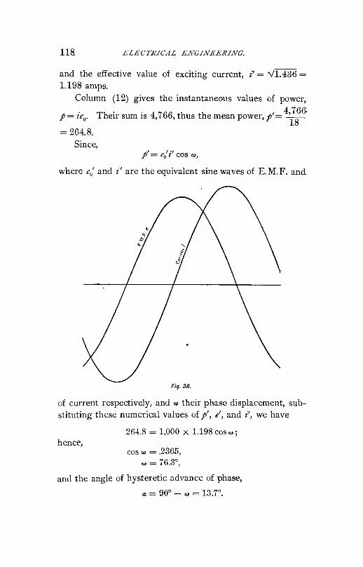
iia ELECTRICAL ENGJNEERING.
and the effective value of exciting current, i' = Vl.486 =1.198 amps.
Column (12) gives the instantaneous values of power,A ^ f* (*•
p = ie^. Their sum is 4,766, thus the mean power, /'=18
= 264.8.
Since,
/'= e^i' cos (1),
where e^ and i' are the equivalent sine waves of E.M.F. and
Fig, 38.
of current respectively, and u their phase displacement, sub-
stituting these numerical values of/', /, and i', we have
264.8 = 1,000 X 1.198 cos «;
hence.
cos 0) = .2365,
0) = 76.3,
and the angle of hysteretic advance of phase,
a = 90° - u> = 13.7°.

EQUIVALENT SINE WAVES. 119
The magnetic energy current is then,
i' COS 0) = .283;
the magnetizing current
;
i' sin o) = 1.166.
Adding the instantanous values of E.M.F. e^ in column
(4), gives 14,648, thus .the mean value, 1^^= 813.8. •
18Since the effective value is 1,000, the mean value of a sine
2 V2wave would be, 1,000 = 904, hence the form factor is,
^=81378="^-
Adding the instantaneous values of current i in column
(10), irrespective of their sign, gives 17.17, thus the mean17 17
value, = .954. Since the effective value = 1.198, the18
form factor is,
1.198 2 V2 ...
The instantaneous values of E.M.F. ^„, current i induc-
tion (B and power/ are plotted in Fig. 37, their correspond-
ing sine waves in Fig. 38.


PART II.
SPECIAL APPARATUS.
INTRODUCTION.
By the direction of the energy transmitted, electric
machines have been divided into generators and motors. By
the character of the electric power they have been dis-
tinguished as direct current and as alternating current
apparatus.
With the advance of electrical engineering, however,
these sub-divisions have become unsatisfactory and insuf-
ficient.
The division into generators and motors is not based on
any characteristic feature of the apparatus, and is thus not
rational. Practically any electric generator can be used as
motor, and conversely, and frequently one and the same ma-
chine is used for either purpose. Where a difference is made
in the construction, it is either only quantitative, as, for
instance, in synchronous motors a much higher armature re-
action is used than in synchronous generators, or it is in
minor features, as direct current motors usually have only
one field winding, either shunt or series, while in generators
frequently a compound field is employed. Furthermore,
apparatus have been introduced which are neither motors
nor generators, as the synchronous machine producing watt-
less lagging or leading current, etc., and the different types
of converters.
The sub-division into direct current and alternating cur-

122 ELECTRICAL ENGINEERING.
rent apparatus is unsatisfactory, since it includes in the same
class apparatus of entirely different character, as the induc-
tion motor and the alternating current generator, or the
constant potential commutating machine, and the rectifying
arc light machine.
Thus the following classification, based on the charac-
teristic features of the apparatus, has been adopted by the
A. I. E. E. Standardizing Committee, and is used in the fol-
lowing discussion. It refers only to the apparatus trans-
forming between electric and electric, and between electric
and mechanical power.
1st. Commutating machines, consisting of a uni-direc-
tional magnetic field and a closed coil armature, connected
with a multi-segmental commutator.
2d. Synchronons machines, consisting of a uni-direc-
tional magnetic field and an armature revolving relatively to
the magnetic field at a velocity synchronous with the fre-
quency of the alternating current circuit connected thereto.
3d. Rectifying apparatus ; that is, apparatus reversing
the direction of an alternating current synchronously with
the frequency.
4th. Induction m.achines, consisting of an alternating
magnetic circuit or circuits interlinked with two electric cir-
cuits or sets of circuits, moving with regard to each other.
6th. Stationary Induction apparatus, consisting of a
magnetic circuit interlinked with one or more electric
circuits.
6th. Electrostatic and electrolytic apparatus, as con-
densers and polarization cells.
Apparatus changing from one to a different form of
electric energy have been defined as :
A. — Transformers, when using magnetism, and as
B. — Converters, when using mechanical momentum as
intermediary form of energy.
The transformers as a rule are stationary, the converters
rotary apparatus. Motor-generators transforming from

INTRODUCTION. 123
electrical over mechanical to electric power by two, separate
machines, and dynamotors, in which these two machines are
combined in the same structure, are not included under con-
verters.
1. Conimictating machines as generators are usually built
to produce constant potential for railway, incandescent light-
ing, and general distribution. Only rarely they are designedfor approximately constant power for electro-metallurgical
work, or approximately constant current for series incan-
descent or arc lighting. As motors commutating machinesgive approximately constant speed, — shunt motors, — or
large starting torque, — series motors.
When inserted in series in a circuit, and controlled so as
to give an E.M.F. varying with the ccnditions of load on the
system these machines are "loosieis," and are generators
when raising the voltage, and motors when lowering it.
Commutating machines may be used as dhrct current
converters by transforming power from one side to the other
side of a three-wire system.
2. While in commutating machines the magnetic field
is almost always stationary and the armature rotating,
synchronous machines are built with stationary field and re-
volving armature, or with stationary armature and revolving
field, or inductor machines with stationary armature and
stationary field winding, but revolving magnetic circuit.
By the number and character of the alternating circuits
connected to them they are single-phase or polyphase ma-
chines. As generators they comprise practically all single-
phase and polyphase alternating current generators, as
motors a very important class of apparatus, the synchronous
motors, which are usually preferred for laige powers,
especially where frequent starting and considerable starting
torque are not needed. Synchronous machines may be used'
as compensators to produce wattless current, leading by over-
excitation, lagging by under-excitation, or may be used as
phase converters by operating a polyphase synchronous

124 ELECTRICAL ENGINEERING.
motor by one pair of terminals from a single-phase circuit.
The most important class of converters, however, are the
synchronous commutating machines, to which, therefore, a
special chapter will be devoted in the following.
Synchronous commutating machines contain a uni-direc-
tional magnetic field and a closed circuit armature'connected
simultaneously to a segmental direct current commutator
and by collector rings to an alternating circuit, mostly a
polyphase system. These machines thus can either receive
alternating and yield direct current power as synchronous
converters, or simply "converters," or receive direct and yield
alternating current power as inverted converters, or driven
by mechanical power yield alternating and direct current as
double current generators. Or they can combine motor and
generator action with their converter action. Thus a com-
mon combination is a synchronous converter supplying a
certain amount of mechanical power as synchronous motor.
3. Rectifying Machines are apparatus which by a syn-
chronously revolving rectifying commutator send the succes-
sive half waves of an alternating single-phase or polyphase
circuit in the same direction into the receiving circuit. Themost important class of such apparatus are the open coil
arc light machines, which generate the rectified E.M.F. at
approximately constant current, in a star-connected three-
phase armature in the Thomson-Houston, as quarter-phase
E.M.F. in the Brush arc-light machine.
4. Induction machines are generally used as motors,
polyphase or single-phase. In this case they run at practi-
cally constant speed, slowing down slightly with increasing
load. As generators the frequency of the E.M.F. supplied
by them differs from and is lower than the frequency of
rotation, but their operation depends upon the phase rela-
tion of the external circuit. As phase converters induction
machines can be used in the same manner as synchronous
machines. Their most important use besides as motors is,
however, as frequency converters, by changing from an im-

INTRODUCTION. 125
pressed primary polyphase system to a secondary polyphase
system or different frequency. In this case when lowering
the frequency, mechanical energy is also produced ; when
raising the frequency, mechanical energy is consumed.
6. The most important stationary induction apparatus is
the transformer, consisting of two electric circuits interlinked
with the same magnetic circuit., When using the same or
part of the same electric circuit for primary and secondary,
the transformer is called a compensator or auto-transformer.
When inserted in series into an alternating circuit, and
arranged to vary the E.M.F., the transformer is called
potential regulator or booster. The variation of secondary
E.M.F. may be secured by varying the relative number of
primary and secondary turns, or by varying the mutual
induction between primary and secondary circuit, either
electrically or magnetically. The stationary induction appa-
ratus with one electric circuit are used for producing wattless
lagging currents, as reactive or choking coils.
6. Condensers and polarization cells produce wattless
leading currents, the latter, however, at a very low effi-
ciency, while the efficiency of the condenser is extremely
high, frequently above 99% ; that is, the loss of energy is less
than 1% of the apparent volt-ampere input.
To this classification may be added the uni-polar, or,
more correctly, non-polar machine, in which a conductor
cuts a magnetic field at a uniform rate. Thus far these
machines do not appear of any practical value.
Regarding apparatus transforming between electric energy
and forms of energy differing from electric or mechanical
energy: The transformation between electrical and chemical
energy is represented by the primary and secondary battery
and the electrolytic cell. The transformation between elec-
trical and heat energy by the thermopile, and the electric
heater or electric furnace. The transformation between
electrical and light energy by the incandescent and arc
lamps.

126 ELECTRICAL ENGINEERING.
A. SYNCHRONOUS MACHINES.
I. General.
The most important class of alternating current appa-
ratus consists of the synchronous machines. They com-
prise the alternating current generators, single-phase and
polyphase, the synchronous motors, the phase compensators
and the exciters of induction generators, that is, synchronous
machines producing wattless lagging or leading currents,
and the converters. Since the latter ccmbine features of
the commutating machines with those of the synchronous
machines .they will be considered separately.
In the synchronous machines the terminal voltage and
the induced E.M.F. are in synchronism with, that is, of the
same frequency as, the speed of rotation.
These machines consist of an armature, in which E.M.F.
is induced by the rotation relatively to a magnetic field, and
a continuous magnetic field, excited either by direct current,
or by the reaction of displaced phase armature currents, or
by permanent magnetism.
The formula of induction of synchronous machines, or
commonly called alternators, is,
E = \l2iTNn^ = i.UMi^,
where n is the number of armature turns in series interlinked
with the magnetic flux <l> (in ml. per pole), and JV the fre-
quency of rotation (in hundreds of cycles per sec), E the
E.M.F. induced in the armature turns.
This formula assumes a sine wave of E.M.F. If the
E.M.F. wave differs from sine shape, the E.M.F, is

SYNCHRONOUS MACHINES. 127
where y = form factor of the wave, or "-—- times ratio ofTT
effective to mean value of wave.
The form factor y depends upon the wave shape of the
induced E.M.F. The wave shape of E.M.F. induced in
a single conductor on the armature surface is identical with
that of the distribution, of magnetic flux at the armature
surface and will be discussed more fully in the chapter on
Commutating Machines. The wave of total E.M.F. is the
sum of the waves of E.M.F. in the individual conductors,
added in their proper phase relation, as corresponding to
their relative positions on the armature surface.
In a F or star-connected three-phase machine, if E^ =E.M.F. per circuit, cr Y or star E.M.F., E = E^^% is
the E.M.F. between terminals or A or ring E.M.F., since
two E.M.F.'s displaced by 60° are connected in series be-
tween terminals (V3 = 2 cos 60°).
In a A-connected three-phase machine, the E.M.F. per
circuit is the E.M.F. between the terminals, or A E.M.F.
In a y^connected three-phase machine, the current per
circuit is the current issumg from each terminal, cr the line
current, or y current,
In a A-connected three-phase machine, if T^ = current per
circuit, or A current, the current issuing from each terminal,
or the line or F current, is
Thus in a three-phase system, A current and E.M.F.,
and Y current and E.M.F. (or ring and star current and
E.M.F. respectively), are to be distinguished. They stand
in the proportion : 1 h- V3.
As a rule, when speaking of current and of E.M.F in a
three-phase system, under current the Y current or current
per line, and under E.M.F., the E.M.F. or E.M.F.
between lines is understood.

128 ELECTRICAL ENGINEERING.
II. E.M.F.'s.
In a synchronous machine we have to distinguish be-
tween terminal voltage E, real induced E.M.F. E^, virtual
induced E.M.F. E^ and nominal induced E.M.F. E^^.
The real induced E.M.F. E.^ is the E.M.F. induced in
the alternator armature turns by the resultant magnetic
flux, or magnetic flux interlinked with them, that is, by the
magnetic flux passing through the armature core. It is
equal to the terminal voltage plus the E.M.F. consumed 'by
the resistance of the armature, these two E.M.F.'s being
taken in their proper phase relation,
where / = current in armature, r = effective resistance.
The virtual induced E.M.F. E^ is the E.M.F. which,
would be induced by the flux produced by the field poles, or
flux corresponding to the resultant M.M.F., that is, the resul-
tant of the M.M.F.'s of field excitation and of armature
reaction. Since the magnetic flux produced by the arma-
ture, or flux of armature self-induction, combines with the-
field flux to the resultant flux, the flux produced by the field,
poles does not pass through the armature completely, and
the virtual E.M.F. and the real induced E.M.F. differ from
each other by the E.M.F. of armature self-induction; but
the virtual induced E.M.F., as well as the E.M.F. induced in
the armature by self-induction, have no real and independent
existence, but are merely fictitious components of the real
or resultant induced E.M.F. E^.
The virtual induced E.M.F. is,
^2= ^1 4- Ix,
where x is the self-inductive armature reactance, and the-
E.M.F. consumed by self-induction Ix, is to be combined
with the real induced E.M.F. E^ in the proper phase relation.
The noniinal induced E.M.F. E^ is the E.M.F. which
would be induced by the field excitation if there were neither-

SYNCHRONOUS MACHINES. 129
self-induction nor armature reaction, and the saturation were
the same as corresponds to the real induced E.M.F. It
thus does not correspond to any magnetic flux, and has no
existence at all, but is merely a fictitious quantity, which,
however, is -very useful for the investigation of alternators
by allowing the combination of armature reaction and self-
induction into a single effect, by a (fictitious) self-induction
or synchronous reactance x^. The nominal induced E.M.F.
would be the terminal voltage at open circuit and full load
excitation if the saturation curve were a straight line.
The synchronous reactance ;ir„ is thus a quantity com-
bining armature reaction and self-induction of the alternator.
It is the only quantity which can easily be determined by
experiment, by running the alternator on short circuit with
excited field. If in this case /„ = current, W^, — loss of power
in the armature coils, E^ = E.M.F. corresponding to the field
Eexcitation at open circuit ; -j = Zf^'is the synchronous im-
'0
w.pedance -jr —''o i^ the effective resistance (ohmic resistance
-o
plus load losses), and x^ = Vr/ — r/ the synchronous re-
actance.
In this feature lies the importance of the term " nominal
induced E.M.F." E,:
these terms being combined in their proper phase relation.
In a polyphase machine, these considerations apply to each
of the machine circuits individually.
III. Armature Reaction.
The magnetic flux in the field of an alternator under
load is produced by the resultant M.M.F. of the field excit-
ing current and of the armature current. It depends upon
the phase relation of the armature current. The E.M.F.
induced by the field exciting current or the nominal in

130 ELECTRICAL ENGINEERING.
duced E.M.F. reaches a maximum when the armature coil
faces the position midway between the field poles, as shown
in Fig. 39, A and A'. Thus, if the armature current is in
i A'
_5 I I
r -^^^N ^ ' '
• 6
' '' S
~l 1 ' ~
c-«—P 5—*
—
\ '
—
'
2=1 !
~^;
;=K^ 3 '
I;\
' -En, .^2_; :
—=!—
^GENERATOR
Fig. 39.
__S ( (
phase with the nominal induced E.M.F., it reaches its maxi-
mum in the same position A, A' of armature coil as the
nominal induced E.M.F., and thus magnetizes the preceding,
demagnetizes the following magnet pole (in the direction of
rotation) in an alternating current generator A ; magnetizes
the following and demagnetizes the preceding magnet pole
in a synchronous motor. A' (since in a generator the rotation
is against, in a synchronous motor with the magnetic
attractions and repulsions between field and armature). In
this case the armature current neither magnetizes nor
demagnetizes the field as a whole, but magnetizes the one
side, demagnetizes the other side of each field pole, and thus
merely distorts the magnetic field.
If the armature current lags behind the nominal induced
E.M.F. , it reaches its maximum in a position where the
armature coil already faces the next magnetic pole, as shown
in Fig. 39, B and B', and thus demagnetizes the field in a
generator, B, magnetizes it in a synchronous motor, B'.

SYATCHRONOUS MACHINES. 131
If the armature current leads the nominal induced
E.M.F., it reaches its maximum in an earlier position, while
the armature coil still partly faces the preceding magnetpole, as shown in Fig. 39, C and C, and thus magnetizes the
field in a generator. Fig. 39, C, and demagnetizes it in a
synchronous motor, C.
With non-inductive load, or with the current in phase
with the terminal voltage of an alternating current generator,
the current lags behind the nominal induced E.M.F., due to
armature reaction and self-induction, and thus partly
demagnetizes ; that is, the voltage is lower under load than
at no load with the same field excitation. That is, lagging
current demagnetizes, leading current magnetizes, the field
of an alternating current generator, while the opposite is the
case with a synchronous motor.
In Fig. 40 let ~0F= £F = resultant M.M.F. of field excita-
tion and armature current (the M.M.F. of the field excitation
being alternating also with
regard to the armature
coil, due to its rotation)
and (Dj the lag of the cur-
rent / behind the virtual
E.M.F. E^ induced by the
resultant M.M.F.
The virtual E.M.F. E^
lags 90° behind the re-
sultant flux of OF, and is
thus represented by OE^
in Fig. 40, and the M. M.F.
of the armature current
/"by Of, lagging by angle
0)2 behind OE^. JThe re-
sultant M.M.F. (9SF is the
diagonal of the parallelo-
gram with the component M.M.F 's Of= armature M.M.F.
and CSFq = total impressed E.M.F. or field excitation, as
Fig. 40.

132 ELECTRICAL ENGINEERING.
sides, and from this construction CSFj is found. CSF„ is thus
the position of the field pole with regard to the armature.
It is trigonometrically,
JF„= VfF2+/^+2g/sinm,.
If / = current per armature turn in amperes effective,
n = number of turns per pole in a single-phase alternator,
the armature reaction is/= n /ampere turns effective, and
is pulsating between zero and n I V2.
In a quarter-phase alternator with n turns per pole, and
phase in series and / amperes effective per turn, the arma-
ture reaction per phase is n I ampere turns effective, and
n J V2 ampere turns maximum. The two phases magnetize
in quadrature, in phase, and in space. Thus at the time t,
corresponding to angle ^ after the maximum of the first
phase, the M.M.F. in the direction by angle <^ behind the
direction of the magnetization of the first phase is nl V2 cos^
<^. The M.M.F. of the second phase is n /V2 sin^ ^, thus
the total M.M.F. or the armature reaction/ = nl^% and is
constant in intensity, but revolves synchronously with regard
to the armature ; that is, it is stationary with regard to the
field.
In a three-phaser of n turns in series per pole, and phase
and /amperes effective per turn, the M.M.F. of each phase
is «/V2 ampere turns maximum, thus at angle <^ in position
and angle </> in time behind the maximum of one phase
;
the M.M.F. of this phase is,
«/V2cos2<^.
The M.M.F. of the second phase is,
«/V2 cos^ (<^ + 120) = «7V2 (-.5 cos ^ -.5 VS sin ^J:
The M.M.F. of the third phase is,
nI-\l2cos'{.^ -H 240) = «/V2(-.6cos<i>+.5 VSsin 4,)\
Thus the total M.M.F. or armature reaction,
/= nl-^ (cos^ ^ -F.25 cos2<^ +.75 sin> +.25 cos=' <^+ .75 sin2<^)
= 1.5«/V2,

SYNCHRONOUS MACHINES. 133
constant in intensity, but revolving synchronously with
regard to the armature, that is, stationary with regard to the
field. These values of armature reaction correspond strictly
only to the case where all conductors of the same phase are
massed together in one slot. If the conductors of each phase
are distributed over a greater part of the armature surface,
the values of armature reaction have to be multiplied by the
average cosine of the total angle of spread of each phase.
IV. Self-induction.
The effect of self-induction is similar to that of armature
reaction, and depends upon the phase relation in the same
manner.
If E^-= real induced voltage, w^= lag of current behind
induced voltage E^, the magnetic flux produced by the arma-
ture current / is in phase with the current, and thus the
counter E.M.F. of self-induction in quadrature behind the
current, and therefore the E.M.F. consumed by self-induction
in quadrature ahead of the current. Thus in Fig. 41, de-
noting EO^ = Ey the induced
E.M.F., the current is, 01 = 1,
lagging (Ujbehind f^j, the E.M.F.
consumed by self-induction
OEl', 90° ahead of the current,
and the virtual induced E.M.P".
E^, the resultant OE^ and OE^'
.
As seen, the diagram of E.M.F.'s
of self-induction is similar to'^'
the diagram of M.M.F.'s of armature reaction.
From this diagram we get the effect of load and phase
relation upon the E.M.F. of an alternating current generator.
Let E = terminal voltage per machine circuit,
/ = current per machine circuit,
and 0) = lag of current behind terminal voltage.
Let r = resistance,
X = reactance of alternator armature.

134 ELECTRICAL ENGINEERING.
Then, in the polar diagram, Fig.' 42,
OE = E, the terminal voltage, assumed as zero vector.
0/ = I, the current, lagging by angle EOI= <o.
The E.M.F. con-
sumedby resistance
is,
0E-^= Ir in phase
with 01.
The E.M.F. con-
sumed by react-
ance,
6e; = Ix, _90°'
ahead of OI.
The real induced E.M.F. is found by
combining OE and 0E-[ to,
The virtual induced E.M.F. is OE.^
and OE^ combined to
OE^=E^.
The M.M.F. required to produce this E.M.F. Ey is OF"S, 90° ahead of OE^. It is the resultant of armature
Fig. 43.
M.M.F. or armature reaction, and of impressed M.M.F. or
field excitation. The armature M.M.F. is in phase with the
current /, and is nl in a single-phaser, n V2 / in a quarter-

SYNCHRONOUS MACHINES. 135
Phaser, 1.5 V2 «/in a three-phaser, if « = number of arma-ture turns per pole and phase. The M.M.F. of armaturereaction^ is represented in the diagram by <97=/ in phasewith or, and the impressed M.M.F. or field excitation C?„=_CF(| is the side of a parallelogram with CS as diagonal and
Of as other side. Or the M.M.F. consumed by armature
reaction is represented by Of'=f in opposition to Ol.
Combining Of and CSF gives (5F„= SFj, the field excitation.
Fig. 44,
ct'oo—
Fig. 45.
In Figs. 43, 44, 45 are drawn the diagrams
for o) = zero or non-inductive load, <u = 60°, or
60° lag (inductive load of power factor .50), and'
01 = — 60°, or 60° lead (anti-inductive load of
power factor .60).
As seen, with the same terminal voltage £,
with inductive load a much higher, with anti-
inductjve load a lower, field excitation fF„ is re-
quired than with non-inductive load. At open
circuit the field excitation required to produce
E
excitation SF^ with non-inductive load.
Inversely, at constant field excitation, the voltage of an
alternator drops at non-inductive load, drops much more with
inductive load, and drops less, or even rises, with anti-
inductive load.
a-c
terminal voltage .£ would be -^ JF = Wg^, or less than the field
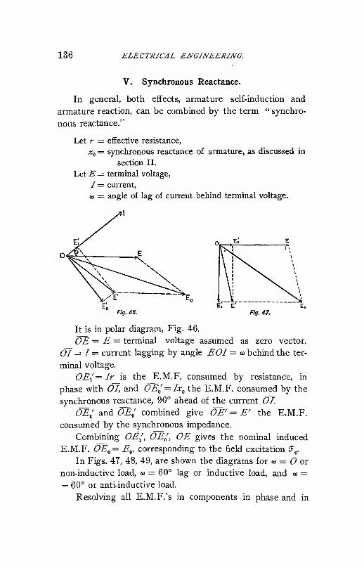
136 ELECTRICAL ENGINEERING.
V. Synchronous Reactance.
In general, both effects, armature self-induction and
armature reaction, can be combined by the term " synchro-
nous reactance."
Let r = effective resistance,
Xf^ = synchronous reactance of armature, as discussed in
section II.
LetE = terminal voltage,
/= current,
o) = angle of lag of current behind terminal voltage.
Fig. 46. Fig. 47.
It is in polar diagram, Fig. 46.
OE = E = terminal voltage assumed as zero vector.
01 = / = current lagging by angle EOI = w behind the ter-
minal voltage.
0E-[= Ir is the E.M.F. consumed by resistance, in
phase with 01, and OEl=IXf^ the E.M.F. consumed by the
synchronous reactance, 90° ahead of the current 01.
OE; and OE^ combined give OE' = E' the E.M.F.
consumed by the synchronous impedance.
Combining OE^, OE^, OE gives the nominal induced
E.M.F. OEf,= Eg, corresponding to the field excitation JF(,.
In Figs. 47, 48, 49, are shown the diagrams for w = or
non-inductive load, o) = 60° lag or inductive load, and u =— 60° or anti-inductive load.
Resolving all E.M.F.'s in components in phase and in
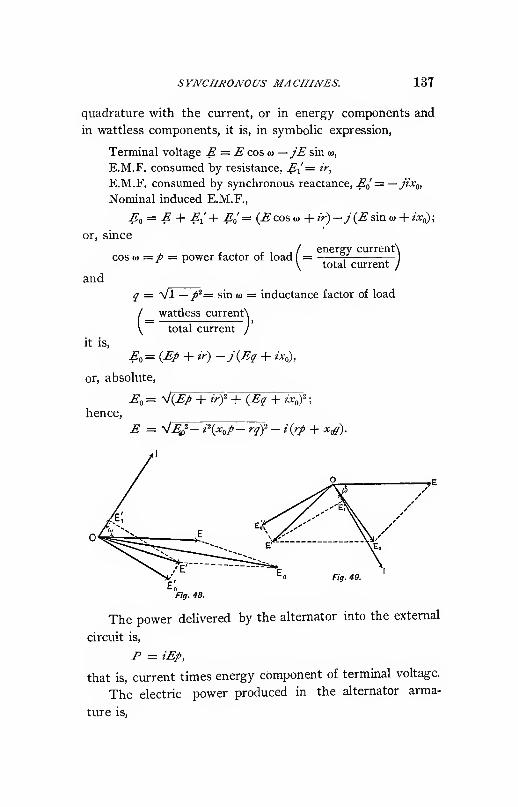
SYNCHRONOUS MACHINES. 137
quadrature with the current, or in energy components and
in wattless components, it is, in symbolic expression,
Terminal voltage E = E cos « —jE sin u,
E.M.F. consumed by resistance, E-[^= ir,
E.M.F. consumed by synchronous reactance, E^ = — jix^,
Nominal induced E.M.F.,
Ea = E -\- £[-{ Ea = (E cos a> + ir)—j {E sin w + ix^;
or, since
, , energy currentNcos ij> =p — power factor of load = ^ —
and
it is.
total current
q = Vl —p^= sin (1) = inductance factor of load
wattless currentN
total current /(-
E^ = {Ep + ir) -j{Eq + ix^,
or, absolute,
E^= sJiEp + irf+iEq + ix.f;
hence.
E = V^/- i\x^p- rqf - i{rp + x^).
Fig. 49.
Fig. 48.
The power delivered by the alternator into the external
circuit is,
F = iEp,
that is, current times energy component of terminal voltage.
The electric power produced in the alternator arma-
ture is,

138 ELECTRICAL ENGINEERING
that is, current times energy component of nominal induced
E.M.F., or, what is the same, current times energy component
of real induced E.M.F.

SYNCHRONOUS MA CHINES. 139
VI. Characteristic Curves of Alternating Current Generator.
In Fig. 50 are shown, at constant terminal voltage E, the
values of nominal induced E.M.F. E^, and thus of field exci-
tation {F(^ with the current / as abscissae and for the three
conditions,
1). Non-ipductive load, / = 1, ^ = 0.
2). Inductive load of lo = 60° lag,/ = .h, q = .866.
3). Anti-inductive load of— (1=60° lead,/ =.5, ^=—.866.

140 ELECTRICAL ENGINEERING.
terminal voltage E with the current I as abscissae and for
the same resistance and synchronous reactance r = .1, ;tr„= 5,
for the three different conditions :
1). Non-inductive load,/ = 1, j' = 0, Ea= 1,121.
2). Inductive load of 60° lag,
/ = .5, ^ = .866, ^0 = 1,468.
3). Anti-inductive load of 60° lead,
/ = .5, q = - .866, E^ = 628.
The values of E^ (and thus of JFo) are assumed so as to
give £ = 1000 at /"= 100. These curves are called the
"Field Characteristics" of the alternator, or the "Regula-
tion Curves " of the synchronous generator.

SYNCHRONOUS MACHINES. 141
In Fig. 52 are shown the "Load Curves" of the ma-chine, with the current / as abscissae and the watts output
as ordinates corresponding to the same three conditions as
Fig. 51. From the field characteristics of the alternator
are derived the open-circuit voltage of 1127 at full non-
inductive load excitation, = 1.127 times full load voltage;
the short-circuit current 225 at full non-inductive load exci-
tation, = 2.25 times full-load current; and the maximum out-
put, 121 K.W., at full non-inductive load excitation, = 1.24
times rated output, at voltage 775 and current 160 amperes.
On the point of the field characteristic on which the alter-
nator works depends whether it tends to regulate for, that
is, maintain, constant voltage, or constant current, or con-
stant power.
VII. Synchronous Motor.
As seen in the preceding, in an alternating current
generator the field excitation required for a given terminal
voltage and current depends upon the phase relation of the
external circuit or the load. Inversely in a synchronous
motor, the phase relation of the current
flowing into the armature at a given
terminal voltage depends upon the field
excitation and the load.
Thus, if ^ = terminal voltage or
impressed E.M.F., / = current, m = lag
of current behind impressed E.M.F. in
a synchronous motor of resistance r
and synchronous reactance x^ the polar
diagram is as follows. Fig. 53.
OE = E \s the terminal voltage assumed as zero vector.
The current 01 = I lags by angle EOI = a>.
The E.M.F. consumed by resistance, is OE\=Ir. The
E.M.F. consumed by synchronous reactance, 0E^= Ix^.
Thus, combining 0E( and OE^ gives OE', the E.M.F. con-
sumed by the synchronous impedance. The E.M.F. con-

142 ELECTRICAL ENGIAEERING.
sumed by the synchronous impedance 6>^', and the E.M.F.
consumed by the nominal induced or counter E.M.F. of the
synchronous motor OE^, combined, give the impressed
E.M.F. OE. Hence OE^^ is one side of a parallelogram,
with OE^ as the other side, and OE as diagonal. OE^f^ equal
and opposite OE^, would thus be the nominal counter
. E.M.F. of the synchronous motor.
In Figs. 54, 55, 56, are shown the polar diagrams of
the synchronous motor for w = 0°, <o =z= 60°, <o = — 60°. As
F\g. se.
seen, the field excitation has to be higher with leading,
lower with lagging current in a synchronous motor, while
the opposite is the case in an alternating current generator.
In symbolic representation, by resolving all E.M.F.'s in
energy components in phase with the current and wattless
components in quadrature with the current t, we have.

SYNCHRONOUS MACHINES. 143
Terminal voltage, E = E cos w —jE sin co = Ep —jEq.
E.M.F. consumed by resistance, El = ir.
E.M.F. consumed by synchronous reactance, ^o' = — jiXfj.
Thus the E.M.F. consumed by nominal induced E.M.F.,
or motor counter E.M.F.
Eff =: E — E-[ — E^ = (£ cos <a — ir) — j{E sin lo — i:x.^
= {Ep - ir) -j\Eq - ixl),
or absolute,
-£ = V(.£' cos is> — irf + {E sin <o — ix^^
= ^{Ep - ir)-" + (^^- w,,)^
;
hence,
^ = /C-/ + A-o?) ± V^o' - 2' (-^o/ - 'Y)'-
The power consumed by the synchronous motor is
P = iEp,
that is, current times energy component of impressed
E.M.F.
The mechanical power delivered by the synchronous
motor armature is,
Eo = i{Ep - ir),
that is, current times energy component of nominal induced
E.M.F. Obviously to get the available mechanical power,
the power consumed by mechanical friction and by molecular
magnetic friction or hysteresis, and the power of field excita-
tion, has to be subtracted from this value /"„.
VIII. Characteristic Curves of Synchronous Motor.
In Fig. 57 are shown, at constant impressed E.M.F Ethe nominal counter E.M.F. E^ and thus the field excitation
SF„ required
1.) At no phase displacement, u>= 0, or for the condition
of minimum input
;
2.) For ft) = + 60, or 60° lag
:
p = .5, q = + .866, and
3.) For 0) = - 60, or 60° lead
:
/ = .5, ^ .t. _ .866,

144 ELECTRICAL ENGINEERING.
with the current / as abscissae, for the constants,
^ = .1, *o = 6 ; E = 1,000.

SYNCHRONOUS MACHINES. 145
{Ep — ir) — (hysteresis and friction) as abscissae, and the same
constants r=.l,Xg=5,E= 1000, and constant field excita-
tion (Fg; that is, constant nominal induced or counter E.M.F.
^0=1109 (corresponding to/= l, ^= at 7=100), the values

146 ELECTRICAL ENGINEERING.
Pq= 6 K.W., or /'i = , or no load,
Fa = 50 K.W., or F^ = 45 K.W., or half load,
F^ = 95 K.W., or F^ = 90 K.W., or full load,
, F^ = 140 K.W., or F^ = 135 K.W., or 150% of load.
Such curves are called " Phase Characteristics of the
Synchronous Motor."
We have,
Fa = iEp — /V,
Hence,
Fa 4- ^Vp iE
g=-sJT^\
Ea= -^{Ep - irf + {Eq - ix^\
Similar phase characteristics exist also for the synchron-
ous generator, but are of less interest. As seen, on each
of the four phase characteristics a certain field excitation

SYNCHRONOUS MACHINES. 14T
Thus a relatively high armature reaction is desirable in
a synchronous motor to secure stability ; that is, indepen-
dence of minor fluctuations of impressed voltage or of field
excitation.
The theoretical maximum output of the synchronous
motor, or the load at which it drops out of step, at constant
impressed voltage and frequency is, even with very high
armature reaction, usually far beyond the. heating limits of
the machine. The actual maximum output depends on the
drop of terminal voltage due to the increase of current, and
on the steadiness or uniformity of the impressed frequency,
thus upon the individual conditions of operation, but is as a
rule far above full load.
Hence, by varying the field excitation of the synchronous
motor the current can be made leading or lagging at will,
and the synchronous motor thus offers the simplest means of
producing out of phase or wattless currents for controlling
the voltage in transmission lines, compensating for wattless
currents of induction motors, etc. Synchronous machines
used merely for suppl)ing wattless currents, that is, synchro-
nous motors or generators running light, with over excited
or under excited field, are called synchronous compensators.
They can be used as exciters for induction generators, as com-
pensators for the wattless lagging currents of induction
motors, etc. Sometimes they are called " rotary condensers"
or dynamic condensers when used only for producing leading
currents.
IX. Magnetic Characteristic or Saturation Curve.
The dependence of the induced E.M.F., or terminal volt-
age at open circuit upon the field excitation, is called the
"Magnetic Characteristic," or "Saturation Curve," of the
synchronous machine. It has the same general shape as
the curve of magnetic induction, consisting of a straight part
below saturation, a bend or knee, and a saturated part beyond
the knee. Generally the change from the unsaturated to the

148 ELECTRICAL ENGINEERING
over saturated portion of the curve is more gradual, thus
the knee is less pronounced in the magnetic characteristic of
the synchronous machines, since the different parts of the
magnetic circuit approach saturation successively.
The dependence of the terminal voltage upon the field
excitation, at constant full-load current flowing through the
armature into a non-inductive circuit, is called the " Load
Saturation Curve " of the synchronous machine. It is a
curve approximately parallel to the no-load saturation curve,
but starting at a definite value of field excitation for zero
terminal voltage, the field excitation required to send full-
load current through the armature against its synchronous
impedance.
The ratio, OS JF
is called the " Saturation Coefficient " of the machine. It
gives the ratio of the proportional change of field excitation
required for a change of voltage.
In Fig. 60 is shown the magnetic characteristic or
no-load saturation curve of a synchronous generator, the
load saturation curve and the no-load saturation coefficient,
assuming E — 1000, T = 100 as full-load values.
In the preceding the characteristic curves of synchron-
ous machines were discussed under the assumption that the
saturation curve is a straight line ; that is, the synchronous
machines working below saturation.
The effect of saturation on the characteristic curves of
synchronous machines is as follows : The compounding
curve is impaired by saturation. That is, a greater change
of field excitation is required with changes of load. Under
load the magnetic density in the armature corresponds to the
true induced E.M.F. E^, the magnetic density in the field
to the virtual induced E.M.F. E^. Both, especially the latter,
are higher than the no-load E.M.F. or terminal voltage E in
the generator, and thus a greater increase of field excitation
is required in presence of saturation than in the absence

SYNCHRONOUS MACHINES. 149
thereof. In addition thereto, due to the counter M.M.F. of
the armature current, the magnetic stray field, that is, that
magnetic fiux which leaks from field pole to field pole
through the air, increases under load, especially with induc-
tive load where the armature M.M.F. directly opposes the

150 ELECTRICAL ENGINEERING.
stant field excitation is reduced, the voltage being limited
by saturation. Owing to the greater difference of field ex-
citation between no load and full load in the case of magnetic
saturation, the improvement in regulation is somewhat
lessened however, or may in some circumstances be lost
altogether.
X. Efficiency and Losses.
Besides these curves the efficiency curves are of interest.
The efficiency of alternators and synchronous motors is
usually so high that a direct determination by measuring
the mechanical power and the electric power is less reliable
than the method of adding the losses, and the latter is
therefore commonly used.
The losses consist of,
Resistance loss in the armature or the induced member.
Resistance loss in the field,
Hysteresis and eddy current losses in the magnetic circuit,
Friction and windage losses,
And eventually load losses, that is, eddy currents or hyste-
resis due to the current flowing in the armature under
load.
The resistance loss in the armature is proportional to
the square of the current /.
The resistance loss in the field is proportional to the
square of the field excitation, that is, the square of the
nominal induced Or counter E.M.F. ^„.
The hysteresis loss is proportional to the 1.6th power cf
the real induced E.M.F. E.^ = E±Ir.
The eddy current loss is usually proportional to the
square of the induced E.M.F. E^.
The friction and windage loss is constant.
The load losses vary more or less proportionally to the
square of the current in the armature, and should be small
with proper design. They can be represented by an " effec-
tive " armature resistance.

SYNCBKONOUS MACHINES. 151
Assuming in the preceding instance,
A friction loss of 2000 Vvatts,
A hysteresis loss of 3000 watts, at the induced E.M.F.
E^ = 1000
;
A resistance loss in the field of 800 watts, at E^ = 1000
;
Load loss at full load of GOO watts.
The loss curves and efficiency curves are plotted in Fig.
61 for the generator with the current output at non-inductive
load or o) = as abscissae, and in Fig. 62 for the synchronous
motor, with the rnechanical power output as abscissae.

152 ELECTRICAL ENGINEERING.
also, more or less. This is called the unbalancing of the
polyphase generator. It is due to different load or load of
different inductance factor in the different branches.
Inversely in a polyphase synchronous motor, if the
terminal voltages of the different branches are unequal, due
to an unbalancing of the polyphase circuit, the synchronous
motor takes more current or lagging current from the branch
of higher voltage, and thereby reduces its voltage, and takes

SYNCHRONOUS MACHINES. 153
XII. Starting of Synchronous Motors.
In starting, an essential difference exists between the
single-piiase and the polyphase synchronous motor, in so far
as the former is not self-starting, but has to be brought to
complete synchronism, or in step with the generator, by ex-
ternal means before it can develop torque, while the poly-
phase synchronous motor starts from rest, and runs up to
synchronism with more or less torque.
In starting, the field excitation of the polyphase syn-
chronous motor must be zero or very low.
The starting torque is due to the magnetic attraction of
the armature currents upon the remanent magnetism left
in the field poles by the currents of the preceding phase, or
the eddy currents induced therein.

154 ELECTRICAL ENGINEERING.
ture has a position a, the maximum induced magnetism in
the field pole face still has the position b, and is thus attracted
towards a, causing the field to revolve in the direction of
the arrow A (or with a stationary field, the armature to
revolve in the opposite direction E).
Lamination of the field poles reduces the starting torque
caused by induced currents in the field poles, but increases
that caused by remanent magnetism or hysteresis, due to
the higher permeability of the field poles. Thus the torque
per volt ampere input is approximately the same in either
case, but with laminated poles the impressed voltage required
in starting is higher and the current lower than with solid
field poles. In either case at full impressed E.M.F., the start-
ing current of a synchronous motor is large, since in the
absence of a counter E.M.F. the total impressed E.M.F. has
to be consumed by the impedance of the armature circuit.
Since the starting torque of the synchronous motor is due
to the magnetic flux induced by the alternating armature
currents or the armature reaction, synchronous motors of
high armature reaction are superior in starting torque.
XIII. Parallel Operation.
Any alternator can be operated in parallel, or synchronized
with any other alternator. A single-phaser can be synchro-
nized with one phase of a polyphaser, or a quarter-phase
machine operated in parallel with a three-phase machine by
synchronizing one phase of the former with one phase of the
latter. Since alternators in parallel must be in step with
each other and have the same terminal voltage, the condition
of satisfactory parallel operation is that the frequency of
the machines is identically the same, and the field excitation
such as would give the same terminal voltage. If this is
not the case, cross currents will flow between the alternators
in a local circuit. That is, the alternators are not without
current at no load, and their cun-ents under load are not of

SYA-CI-IROArOUS MACHINES. 155
the same phase and proportional to their respective capa-
cities. The cross currents flowing between alternators
when operated in parallel can be wattless currents or energy-
currents.
If the frequencies of two alternators are identically the
same, but the f;eld excitation not such as would give equal
terminal voltage when operated in parallel, a local current
flows between the two machines which is wattless and lead-
ing or magnetizing in the machine of lower field excitation,
lagging or demagnetizing in the machine of higher field
excitation. At load this wattless current is superimposed
upon the currents flowing from the machine into the external
circuit. In consequence thereof the current in the machine
of higher field excitation is lagging behind the current in the
external circuit, the current in the machine of lower field
excitation leads the current in the external circuit. The
currents in the two machines are thus out of phase with each
other, and their sum larger than the joint current, or current
in the external circuit. Since it is the armature reaction of
leading or lagging current which makes up the difference
between the impressed field excitation and the field excita-
tion required to give equal terminal voltage, it follows that
the lower the armature reaction, that is, the closer the regu-
lation of the machines, the more sensitive they are for
inequalities or variations of field excitation. Thus, too low
armature reaction is undesirable for parallel operation.
With identical machines the changes in field excitation
required for changes of load must be the same. With mr.-
chines of different compounding curves the changes of field
excitation for varying load must be different, and such as
correspond to their respective compounding curves, if watt-
less currents shall be avoided. With machines of reason-
able armature reaction the wattless cross, currents are small,
even with relatively considerable inequality of field excita-
tion. Machines of high armature reaction have been oper-
ated in parallel under circumstances where one machine

156 ELECTRICAL ENGINEERING.
was entirely without field excitation, while the other carried
twice its normal field excitation, with wattless currents,
however, of the same magnitude as full-load current.
XIV. Division of Load in Parallel Operation.
Much more important than equality of terminal voltage
before synchronizing is equality of frequency. Inequality of
frequency, or rather a tendency to inequality of frequency
(since by necessity the machines hold each other in step
or at equal frequency), causes cross currents to flow which
transfer energy from the machine whose driving power tends
to accelerate to the machine whose driving power tends to
slow down; and thus relieves the latter, by increasing the load
on the former. Thus these cross currents are energy cur-
rents, and cause at no load or light load the one machine to
drive the other as synchronous motor, while under load the
result is that the machines do not share the load in propor-
tion to their respective capacities.
The speed of the prime mover, as steam engine or tur-
bine, changes with the load. The frequency of alternators
driven thereby must be the same when in parallel. Thus
their respective loads are such as to give the same speed of
the prime mover (or rather a speed corresponding to the
same frequency). Hence the division of load between alter-
nators connected to independent prime movers depends
almost exclusively upon the speed regulation of the prime
movers. To make alternators divide the load in propor-
tion to their capacities, the speed regulation of their prime
movers must be the same, that is, the engines or turbines
must drop in speed from no load to full load by the same
percentage and in the same manner.
If the regulation of the prime movers is not the same,
the load is not divided proportionally between the alternators,
but the alternator connected to the prime mover of closer
speed regulation takes more than its share of the load under
SYNCHRONOUS MACHINES. 157
heavy loads, or less under light loads. Thus, too close
speed regulation of prime movers is not desirable in parallel
operation of alternators.
XV. Fluctuating Cross Currents in Parallel Operation.
In alternators operated from independent prime movers,
it is not sufficient that the average frequency corresponding
to the average speed of the prime movers is the same, but
still more important that the frequency is the same at any
instant, that is, that the frequency (and thus the speed of the
prime mover) is constant. In rotary prime movers, as tur-
bines or electric motors, this is usually the case ; but with
reciprocating machines, as steam engines, the torque and
thus the speed of rotation rises and falls periodically during
each revolution, with the frequency of the engine impulses.
The alternator connected with the engine will thus not have
uniform frequency, but a frequency which pulsates ; that is,
rises and falls; The amplitude of this pulsation depends
upon the type of the engine, and the momentum of its fly-
wheel, and the action of the engine governor.
If two alternators directly connected to equal steam
engines are synchronized so that the moments of maximumfrequency coincide, no energy cross currents flow between
the machines, but the frequency of the whole system rises
and falls periodically. In this case the engines are said to
be synchronized. The parallel operation of the alternators
is satisfactory in this case provided that the pulsations of
engine speeds are of the same size and duration ; but appa-
ratus requiring constant frequency as synchronous motors
and especially rotary converters, when operated from such a
system, will give a reduced maximum output due to periodic
cross currents flowing between the generators of fluctuating
frequency and the synchronous motors of constant frequency,
and in an extreme case the voltage of the whole system will
be caused to fluctuate periodically. Even with small fluctu-

158 ELECTRICAL ENGINEERING.
ations of engine speed the unsteadiness of current due to
this source is noticeable in synchronous motors and rotary
converters.
If the alternators happen to be synchronized in such a
position that the moment of maximum speed of the one
coincides with the moment of minimum speed of the other,
alternately the one and then the other alternator will run
ahead, and thus a pulsating energy cross current flow between
the alternators, transferring power from the leading to the
lagging machine, that is, alternately from the one to the
other, and inversely, with the frequency of the engine im-
pulses. These pulsating cross currents are the most undesir-
able, since they tend to make the voltage fluctuate and to
tear the alternators out of synchronism with each other,
especially when the conditions are favorable to a cumulative
increase of this effect by what may be called mechanical
resonance (hunting) of the engine governors, etc. They de-
pend upon the synchronous impedance of the alternators
and upon their phase difference, that is, the number of poles
and the fluctuation of speed, and are specially objectionable
when operating synchronous apparatus in the system.
Thus, for instance, if two 80-polar alternators are directly
connected to single cylinder engines of 1% speed variation
per revolution, twice during each revolution the speed will
rise, twice fall ; and consequently the speed of each alter-
nator will be above average speed during a quarter revolu-
tion. Since the maximum speed is i% above average, the
mean speed during the quarter revolution of high speed is
1% above average speed, and by passing over 20 poles the
armature of- the machine will during this time run ahead of
its mean position by \ofo of 20 or ^'^ pole, that is VV" = ^°
If the armature of the other alternator at this moment is
behind its average position by 9°, the phase displacement
between the alternator E.M.F.'s is 18°; that is, the alter-
nator E.M.F.'s are represented by OE.^ and OE^ in Fig, 64,
and when running in parallel the E.M.F. OE'= E^E^ is

SYNCHRONOUS MACHINES. 159
short circuited through the synchronous impedance of the
two alternators.
Since E'= 0E^= 2 E^ sin 9°, the maximum cross cur-
rent is
/'= ^isin9° .156^1 = .156 7„,
pwhere I^= ^= short circuit current of alternator at full-
load excitation. Thus if the short circuit current of the
alternator is only twice full-load current, the cross current
is 31.2% of full-load cur-
rent. If the short circuit
current is 6 times full-load
current, the cross current 0,*
is 96.3% of full-load cur-
Fig. 64.
rent or practically equal
to full-load current. Thus
the smaller the armature
reaction or the better the
regulation, the larger are
the pulsating cross currents flowing between the alternators,
due to inequality of the rate of rotation of the prime movers.
Hence for satisfactory parallel operation of alternators con-
nected to steam engines, a certain amount of armature re-
action is desirable and very close regulation undesirable.
By the transfer of energy between the machines the
pulsations of frequency, and thus the cross currents, are
reduced somewhat. Very high amature reaction is objec-
tionable also, since it reduces the synchronizing power, that
is, the tendency of the machines to hold each other in step,
by reducing the energy transfer between the machines.
As seen herefrom, the problem of parallel operation of
alternators is almost entirely a problem of the regulation of
their prime movers, especially steam engines, but no electrical
problem at all.
From Fig. 64 it is seen that the E.M.F. ~0E' or ~E^„

160 ELECTRICAL ENGINEERING.
which causes the cross current between two alternators in
parallel connection, if their E.M.F.'s OE^ and OE^ are out
of phase, is approximately in quadrature with the E.M.F.'s
VE^ and OE^ of the machines, if these latter two E.M.F.'s
are equal to each other. The cross current between the
machines lags behind the E.M.F. producing it, OE', by the
PC
angle w, where tan w = — , and x^ = synchronous reactance,,
r^ = eifective resistance of alternator armature. The energy
component of this cross current, or component in phase with
OE', is thus in quadrature with the machine voltages OE.^
and OE^, that is, transfers no power between them but the
power transfer or equalization, of load between the two
machines takes place by the wattless or reactive component
of cross current, that is, the component which is in quadra-
ture with OE', and thus in phase with one, and in opposition
with the other of the machine E.M.F.'s OE^ and OE^Hence, machines without reactance would have no syn-
chronizing power, or could not be operated in parallel. The
theoretical maximum synchronizing power exists if the syn-
chronous reactance equals the resistance : x^ = ;'„. This
condition, however, cannot be realized, and if realized would
give a dangerously high synchronizing power and cross cur-
rent. In practice, x^ is always very much greater than r„,
and the cross current thus practically in quadrature with
OE', that is, in phase (or opposition) with the machine volt-
ages, and is consequently an energy-transfer current.
If, however, the machine voltages OE^ and OE^ are dif-
ferent in value but approximately in phase with each other,
the voltage causing cross currents, E.^E^ is in phase with
the machine voltages and the cross currents thus in quadra-
ture with the machine voltages OE^ and OE^ and hence do
not transfer energy, but are wattless. In one machine the
cross current is a lagging or demagnetizing, and in the
other a leading or magnetizing, current.
Hence two kinds of cross currents may exist in parallel

SYNCHRONOUS MACHINES. 161
operation of alternators,— currents transferring power be-
tween the machines, due to phase displacement between
their E.M.F.'s, and wattless currents transferring magne-
tization between the machines, due to a difference of their
induced E.M.F.'s.
In compound-wound alternators, that is, alternators in
which the field excitation is increased with the load by
means of a series field excited by the rectified alternating
current, it is almost, but not quite, as necessary as in direct
current machines, when operating in parallel, to connect all
the series fields in parallel by equalizers of negligible resist-
ance, for the same reason,— to ensure proper division of
current between machines.
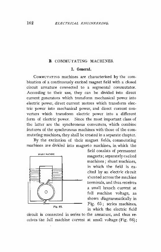
162 ELECTRICAL ENGINEERING.
B. COMMUTATING MACHINES.
I. General.
CoMMUTATiNG machines are characterized by the com-
bination of a continuously excited magnet field with a closed
circuit armature connected to a segmental commutator.
According to their use, they can be divided into direct
current generators which transform mechanical power into
electric power, direct current motors which transform elec-
tric power into mechanical power, and direct current con-
verters which transform electric power into a different
form of electric power. Since the most important class of
the latter are the synchronous converters, which combine
features of the synchronous machines with those of the com-
mutating machines, they shall be treated in a separate chapter.
By the excitation of their magnet fields, commutating
machines are divided into magneto machines, in which the
field consists of permanentSHUNT MACHINE
magnets; separately excited
machines ; shunt machines,
in which the field is ex-
cited by an electric circuit
shunted across the machine
terminals, and thus receives
a small branch current at
full machine voltage, as
shown diagrammatically in
Fig. 65 ; series machines,
in which the electric field
circuit is connected in series to the armature, and thus re-
ceives the full machine current at small voltage (Fig. 66)
;
Fig. 65.

COMMUTA TING MA CHINES. 163
and compound machines excited by a combination of shunt
and series field (Fig. 67). In compound machines the twowindings can magnetize either in the same direction (cumu-
lative compounding), or in opposite directions (differential
COMPOUND MACHINE
SERIES MACHINE
Fig. ee. Fig. 67.
compounding). Differential compounding has been used for
constant-speed motors. Magneto machines are used only
for very small sizes.
By the number of poles commutating machines are
divided into bipolar and multipolar machines. Bipolar ma-
chines are used only in small sizes. By the construction of
the armature, commutating machines are divided in smooth-
core machines, and iron-clad or "toothed " armature ma-
chines. In the smooth-core machine the armature winding
is arranged on the surface of a laminated iron core. In the
iron-clad machine ths armature winding is sunk into slots.
The iron-clad type has the advantage of greater mechanical
strength, but the disadvantage of higher self-induction in
commutation, and thus requires high resistance, carbon cr
graphite commutator brushes. The iron-clad type has the
advantage of lesser magnetic stray field, due to the shorter
gap between field pole and armature iron, and of lesser mag-
net distortion under load, and thus can with carbon brushes
be operated with constant position of brushes at all loads.
In consequence thereof, for large multipolar machines the

164 ELECTRICAL ENGINEERING.
iron-clad type of armature is generally used, and the smooth-
core ring armature type only for large multipolar, low-voltage
machines, of the 'face commutator type, to secure high
economy of space.
Either of these types can be drum wound or ring wound.
The drum winding has the advantage of lesser self-induction,
and lesser distortion of the magnetic field, and is generally
less difficult to construct and thus mostly preferred, except
in special cases as to secure high economy in space in low-
voltage multipolar machines. By the armature winding, the
commutating machines are divided into multiple wound and
series wound machines. The difference between multiple
and series armature winding, and their modifications, can
best be shown by diagram.
S
MUETI'PLE RING.
fIff. ea

COMMUTATING MACHINES. 165
II. Armature Winding.
Fig. 68 shows a six-polar multiple ring winding, and Fig.
69 a six-polar multiple drum winding. As seen, the armaturecoils are connected progressively all around the armature in
MULTIPLE DRUM, FULL PITCH.
Fig. eg.
closed circuit, and the connections between adjacent armature
coils lead to the commutator. Such an armature winding
has as many circuits in multiple, and requires as many sets of
commutator brushes, as poles. Thirty-six coils are shown in
Figs. 68 and 69, connected to 36 commutator segments, and
the two sides of each coil distinguished by drawn and dotted
lines. In a drum-wound machine, usually the one side of all

166 ELECTRICAL ENGINEERING.
£oils forms the upper and the other side the lower layer of
the armature winding.
Fig. 70 shows a six-polar series drum winding, with 36
slots and 36 commutator segments. In the series winding
SERIES DRUM WITH CROSS-CONNECTED COMMUTATOR.
Fig. 70.
the circuit passes from one armature coil, not to the next
adjacent armature coil as in the multiple winding, but first
through all the armature coils having the same relative
position with regard to the magnet poles of the same polarity,
and then to the armature coil next adjacent to the first coil.
That is, all armature coils having the same or approximately
the same relative position to poles of equal polarity, form
one set of integral coils. Thus the series winding has only

commutaTing machines. 187
two circuits in multiple, and requires two sets of brushes
only, but can be operated also with as many sets of brushes
as poles, or any intermediate number of sets of brushes. In
Fig. 70, a series winding in which the number of armature
coils is divisible by the number of poles, the commutator
segments have to be cross connected.
This form of series winding is hardly ever used. The
usual form of series winding is the winding shown by Fig. 71.
SERIES DRUM.
Fig. 71.
This figure shows a six-polar armature having 35 coils and
35 commutator segments. In consequence thereof, the
armature coils under corresponding poles which are con-
nected in series are slightly displaced from each other, so

168 ELECTRICAL EXGLXEERLiVG.
that after passing around all corresponding poles, the wind-
ing leads symmetrically into the coil adjacent to the •first
armature coil. Hereby the necessity of commutator cross
connections is avoided, and the winding is perfectly sym-
metrical. With this form of series winding, which is mostly
used, the number of armature coils must be chosen to follow
OPEN CIRCUIT, THREE PHASE, SERIES BRUtf.
Fig. 72.
certain rules. Generally the number of coils is one less or
one more than a multiple of the number of poles.
All these windings are closed circuit windings ; that is,
starting at any point, and following the armature conductor,
the circuit returns into itself after passing all E.M.F.'s twice
in opposite direction (thereby avoiding short circuit). Aninstance of an open-coil winding is shown in Fig. 72, a series
connected three-phase Y winding similar to that used in the

COMMUTATING MACHINES. 169
Thomson-Houston arc machine. Such open-coil windings,
however, cannot be used in commutating machines. Theyare generally preferred in synchronous and in induction
machines.
By leaving space between adjacent coils of these wind-
ings, a second winding can be laid in between. The second
winding can either be entirely independent from the first
MULTIPLE, DOUBL.E SPIFWL RING.
Fig. 73.
winding ; that is, each of the two windings closed upon
itself, or after passing through the first winding the circuit
enters the second winding, and after passing through the
second winding it reenters the first winding. In the first
case, the winding is called a double spiral winding (or mul-
tiple spiral winding if more than two windings are used), in
the latter case a double re-entrant winding (or multiple re-
entrant winding). In the double spiral winding, the number
of coils must be even ; in the double re-entrant winding, odd.
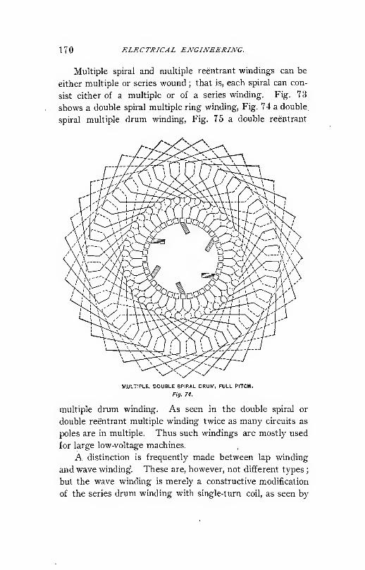
170 ELECTRICAL ENGINEERING.
Multiple spiral and multiple reentrant windings can be
either multiple or series wound ; that is, each spiral can con-
sist either of a multiple or of a series winding. Fig. 73
shows a double spiral multiple ring winding, Fig. 74 a double,
spiral multiple drum winding. Fig. 75 a double reentrant
MULTIPLE, DOUBLE SPIRAL DRUM, FULL PITCH.
Fig. 74.
multiple drum winding. As seen in the double spiral or
double reentrant multiple winding twice as many circuits as
poles are in multiple. Thus such windings are mostly used
for large low-voltage machines.
A distinction is frequently made between lap winding
and wave winding". These are, however, not different types;
but the wave winding is merely a constructive modification
of the series drum winding with single-turn coil, as seen by
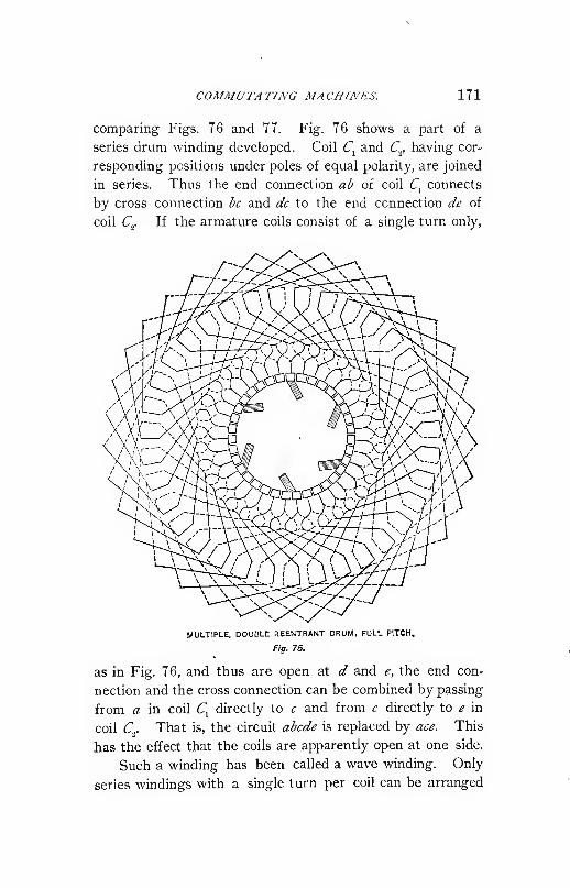
COMMUTATING MACHINES. 171
comparing Figs. 76 and 77. Fig. 76 shows a part of a
series drum winding developed. Coil C^ and Q having cor-
responding positions under poles of equal polarity, are joined
in series. Thus the end connection ab of coil C, connects
by cross connection be and dc to the end connection de of
coil Q If the armature coils consist of a single turn only.
MULTIPLE, DOUBLE REENTRANT DRUM, FULL PITCH.
Fig. 75.
as in Fig. 76, and thus are open at d and e, the end con-
nection and the cross connection can be combined by passing
from a in coil C, directly to c and from c directly to e in
coil Cy That is, the circuit abcde is replaced by ace. This
has the effect that the coils are apparently open at one side.
Such a winding has been called a wave winding. Only
series windings with a single turn per coil can be arranged

172 ELECTRICAL ENGINEERING.
as wave windings, while windings with several turns per coil
must necessarily be lap or coil windings. In Fig. .78 is
shown a series drum winding with 35 coils and commutator
segments, and a single turn per coil arranged as wave
SERIES LAP WINDING
WAVE WINDING.
Fig. 77.
winding. This wmding may be compared with the 35-coil
series drum winding, in Fig. 71.
Drum winding can be divided into full pitch and frac-
tional pitch windings. In the full pitch winding, the spread
of the coil covers the pitch of one pole ; that is, each coil
covers \ of the armature circumference in a six-polar ma-
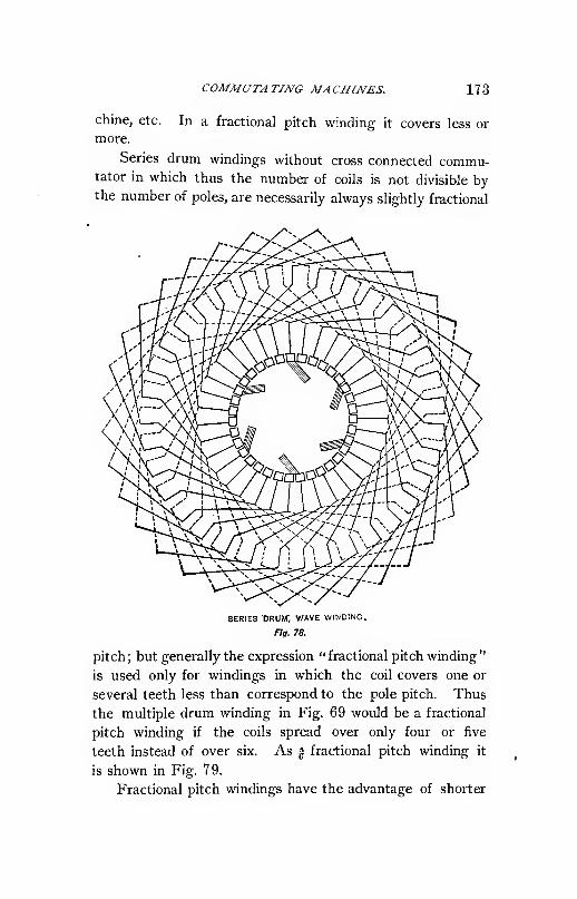
COMMUTATING MACHINES. 173
chine, etc. In a fractional pitch winding it covers less or
more.
Series drum windings without cross connected commu-tator in which thus the number of coils is not divisible bythe number of poles, are necessarily always slightly fractional
SERIES DRUW, WAVE WINDING.
Fig. 78.
pitch; but generally the expression "fractional pitch winding
"
is used only for windings in which the coil covers one or
several teeth less than correspond to the pole pitch. Thus
the multiple drum winding in Fig. 69 would be a fractional
pitch winding if the coils spread over only four or five
teeth instead of over six. As ^ fractional pitch winding it
is shown in Fig. 79.
Fractional pitch windings have the advantage of shorter

174 ELECTRICAL ENGINEERING.
end connections and less self-induction in commutation,
since commutation of corresponding coils under different
poles does not take place in the same, but in different, slots,
and the flux of self-induction in commutation is thus moresubdivided. Fig. 79 shows the multiple drum winding of
MULTIPLE, DRUM Y^ FRACTIONAL PnCH.
Fig. 79.
Fig. 69 as fractional pitch winding with five teeth spread, or
I pitch. During commutation, the coils abcdef commutate
simultaneously. In Fig. 69 these coils lie by two in the
same slots, in Fig. 79 they lie in separate slots. Thus, in
the former case the flux of self-induction interlinked with the
commutated coil is due to two coils ; that is, twice that in
the latter case. Fractional pitch windings, however, have
the disadvantage of reducing the width of the neutral zone,

COMMUTATING MACHINES. 175
or zone without induced E.M.F. between the poles, in which
commutation takes place, since the one side of the coil
enters or leaves the field before the other. Therefore, in
commutating machines it is seldom that a pitch is used that
falls short of full pitch by' more than one or two teeth,
while in induction machines, occasionally as low a pitch as
50 % is used, and % pitch is frequently employed.
Series windings find their foremost application in ma-
chines with small currents, or small machines in which it is
desirable to have as few circuits as possible in multiple, and
in machines in which it is desirable to use only two sets of
brushes, as in railway motors. In multipolar machines with
many sets of brushes, series winding is liable to give selective
commutation ; that is, the current does not divide evenly
between the sets of brushes of equal polarity.
Multiple windings are used for machines of large cur-
rents, thus generally for large machines, and in large low-
voltage machines the still greater subdivision of circuits
afforded by the multiple spiral and the multiple reentrant
winding is resorted to.
To resume, then, armature windings can be subdivided
into
:
a). Ring and drum windings.
V). Closed circuit and open circuit windings. Only the
former can be used for commutating machines,
f). Multiple and series windings.
d). Single spiral, multiple spiral, and multiple reentrant
windings. Either of these can be multiple or series
windings.
e). Full pitch and fractional pitch windings.
III. Induced E.M.F.'S.
The formula of induction of a direct current machine,
as discussed in the precedmg, is :
If = 4 Nn^.

176 ELECTRICAL ENGINEERING.
Wheree = induced E.M.F.
N = frequency = number of pairs of poles X revolutions
per second, in hundreds.
n = number of turns in series between brushes.
$ = magnetic flux passing through the armature per pole,
in megalines.
In ring-wound machines, * is one-half the flux per field
pole, since the flux divides in the armature into two circuits,
and each armature turn incloses only half the flux per field
pole. In ring-wound armatures, however, each armature turn
has only one conductor lying on the armature surface, or face
conductor, while in a drum-wound machine each turn has
two face conductors. Thus, with the same number of face
conductors— that is, the same armature surface— the same
frequency, and the same flux per field pole, the same E.M.F.
is induced in the ring-wound as in the drum-wound armature.
The number of turns in series between brushes, n, is one-
half the total number of armature turns in a series wound
armature, — the total number of armature turns in a single
spiral multiple wound armature with /> poles. It is one-ha'f
as many in a double spiral or double reentrant, one-third as'
many in a triple spiral winding, etc.
By this formula, from frequency, series turns and mag-
netic flux the E.M.F. is found, or inversely from induced
E.M.F., frequency, and series turns, the magnetic flux per
field pole is calculated.
^ = •
From magnetic flux, and section and lengths of the dif-
ferent parts of the magnetic circuit, the densities and the
ampere turns required to produce these densities are derived,
and as the sum of the ampere turns required by the dif-
ferent parts of the magnetic circuit, the total ampere turns
excitation per field pole is found, which is required for
inducing the desired E.M.F.

COMMUTATING MACHINES. 177
Since the formula of direct current induction is indepen-
dent of the distribution of the magnetic flux, or its wave
shape, the total magnetic flux and thus the ampere turns re-
quired therefor, are independent also of the distribution of
magnetic flux at the armature surface. The latter is of
importance, however, regarding armature reaction and
commutation^
IV. Distribution of Magnetic Flux.
The distribution of magnetic flux in the air gap or at the
armature surface can be calculated approximately by assum-
ing the density at any point of the armature surface as pro-
portional to the M.M.F. acting thereon, and inversely
proportional to the nearest distance from a field pole. Thus,
if 7(1 = ampere turns acting upon air gap between armature
and field pole, a = length of air gap, from iron to iron,
the density under magnet pole, that is, in the range BC of
Fig. 80, is
(Bn4^10 a'
3Sii
T'
Fig. 80.
At a point having the distance x from the end of the
field pole on the armature surface, the distance from the next
field pole is ^ = V^MT?, and the density thus,
IwiFi,
10 y/a' + ^
Herefrom the distribution of magnetic flux is calculated
and plotted in Fig. 80, for a single pole BC, along the
armature surface A, for the length of air gap a = 1, and such

178 ELECTRICAL ENGINEERING.
a M.M.F. as to give Cft^ = 8000 under the field pole, that is,
for £F„ = 6400 or 5C, = 8000.
Around the surface of the direct current machine arma-
ture, alternate poles follow each other. Thus the M.M.F.
is constant only under each field pole, but decreases in the
space between the field poles, from (7 to ^ in Fig. 81,
Fig. 81.
from full value at C to full value in opposite direction at £.
The point D midway between C and £, at which the M.M.F.
of the field equals zero, is called the "neutral." The dis-
tribution of M.M.F. of field excitation is thus given by the
line JF in Fig. 81. The distribution of magnetic flux as
shown in Fig. 81 by &, is derived by the formula,
*-io^'Where
This distribution of magnetic flux applies only to the no-
load condition. Under load, that is, if the armature carries
current, the distribution of flux is changed by the M.M.F. of
the armature current, or armature reaction.
Assuming the brushes set at the middle points between
adjacent poles, D and G, Fig. 82, the M.M.F. of the arma-
ture is maximum at the point connected with the commutator
brushes, thus in this case at the points Z> and G, and
gradually decreases from full value at I) to equal but op-
posite value at G, as shown by the line /in Fig. 82, while
the line JF^ gives the field M.M.F. or impressed M.M.F.

COMMUTA TIlVG MA CHINES. 179
If n = number of turns in series between brushes per
pole, i = current per turn, the armature reaction is/= ni
ampere turns. Adding/and EF„ gives the resultant M.M.F.ff, and therefrom the magnetic distribution.
The latter is shown as line (Bi in Fig. 82.
With the brushes set midway between adjacent field
poles, the armature M.M.F. is additive on one side, and sub-
Fig. 82.
tractive on the other side of the center of the field pole.
Thus the magnetic intensity is increased on one iside, and
decreased on the other. The total M.M.F., however, and
thus neglecting saturation, the total flux entering the arma-
ture, are not changed. Thus, armature reaction, with the
brushes midway between adjacent field poles, acts distorting
upon the field, but neither magnetizes nor demagnetizes, if
the field is below saturation.
The distortion of the magnetic field takes place by the
armature ampere turns beneath the pole, or from B to C.
Thus, if V = pole arc, that is, the angle covered by pole face
(two poles or one complete period being denoted by 360°),
vfthe distortmg ampere turns armature reaction are zr-j--
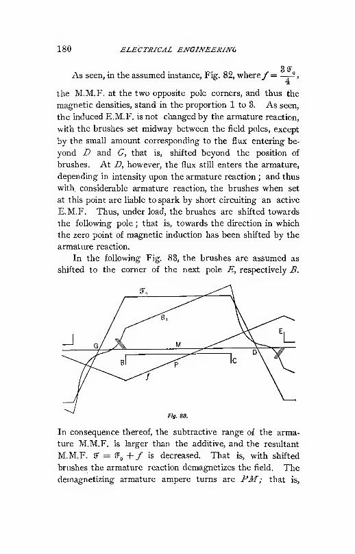
180 ELECTRICAL ENGINEERINC
As seen, in the assumed instance, Fig. 82, where/"=3SF„
the M.M.F. at the two opposite pole corners, and thus the
magnetic densities, stand in the proportion 1 to 3. As seen,
the induced E.M.F. is not changed by the armature reaction,
with the brushes set midway between the field poles, except
by the small amount corresponding to the flux entering be-
yond D and G, that is, shifted beyond the position of
brushes. At D, however, the flux still enters the armature,
depending in intensity upon the armature reaction ; and thus
with considerable armature reaction, the brushes when set
at this point are liable to spark by short circuiting an active
E.M.F. Thus, under load, the brushes are shifted towards
the following pole ; that is, towards the direction in which
the zero point of magnetic induction has been shifted by the
armature reaction.
In the following Fig. 83, the brushes are assumed as
shifted to the corner of the next pole E, respectively B.
Fig. 83.
In consequence thereof, the subtractive range of the arma-
ture M.M.F. is larger than the additive, and the resultant
M.M.F. fF = SF„ +/ is decreased. That is, with shifted
brushes the armature reaction demagnetizes the field. Thedemagnetizing armature ampere turns are P3f; that is.

COMMUTATING MACHINES. 181
GB= ~FT7 f- That is, if h = angle of shift of brushes or angle
of lead (= GB in Fig. 83), assuming the pitch of two poles
= 360', the demagnetizing component of armature reaction
is .„„ , the distorting component is r-— where v = pole arc.
Thus, with shifted brushes the field excitation has to be
increased under load to maintain the same total resultant
M.M.F.; that is, the same total flux and induced E.M.F.
Hence, in Fig. 83 the field excitation ff'^ has been assumed''^¥ f
by T7>77 — q larger than in the previous figures, and the
magnetic distribution (Bj plotted for these values.
V. Effect of Saturation on Magnetic Distribution.
The preceding discussion of Figs. 80 to 83 omits the
effect of saturation. That is, the assumption is made that
the magnetic material near the air gap, as pole face and
armature teeth, are so far below saturation that at the de-
magnetized pole corner the magnetic density decreases, at
the strengthened pole corner increases, proportionally to the
M.M.F.
The distribution of M.M.F. obviously is not affected by
saturation, but the distribution of magnetic flux is greatly
changed thereby. To investigate the effect of saturation,
in Figs. 84 to 87 the assumption has been made that the air
gap is reduced to one-half its previous value, a = .5, thus
CDnsuming only one-half as many ampere turns, and the
other half of the ampere turns are consumed by saturation
of the armature teeth. The length of armature teeth is
assumed as 3.2, and the space filled by the teeth is assumed
as consisting of one-third of iron and two-thirds of non-
magnetic material (armature slots, ventilating ducts, insula-
tion between laminations, etc.).
In Figs. 84, 85, 86, 87, curves are plotted corresponding

182 ELECTRICAL ENGINEERING.
Fig. 84.
Fig. 87.

COMMUTATING MACHINES. 183
to those in Figs. 80, 81, 82, and 83. As seen, the spread
of magnetic induction at the pole corners is greatly increased,
but farther away from the field poles the magnetic distri-
bution is not changed.
The magnetizing, or rather demagnetizing, effect of the
load with shifted brushes is not changed. The distorting
effect of the load is, however, very greatly decreased, to a
small percentage of its previous value, and the magnetic
field under the field pole is very nearly uniform under load.
The reason is: Even a very large increase of M.M.F.
does not much increase the density, the tLmpere turns being
consumed by saturation of the iron, ar.d even with a large
decrease of M.M.F., the density is not decreased much, since
with a small decrease of density the ampere turns corsumed
by the saturation of the iron become available for the gap.
Thus, while in Fig. 88 the densities at the center and
the two pole corners of the field pole are 8000, 12000, and
1000, with the saturated structure in Fig. 87, they are
8000, 9040, and 6550.
At or near the theoretical neutral, however, the satura-
tion has no effect.
That is, saturation of the armature teeth affords a means
of reducing the distortion of the magnetic field, or the
shifting of flux at the pole corners, and is thus advantageous
for machines which shall operate over a wide range of lead
with fixed position of brushes if the brushes are shifted to
near the next following pole corner.
It offers no direct advantage, however, for machines
commutating with the brushes, midway between the field
poles, as converters.
A similar effect to saturation in the armature teeth,, is
produced by saturation of the field pole face, or mere par-
ticularly, saturation of the pole corners of the field,

184 ELECTRICAL ENGINEERING.
VI. Effect of Slots on Magnetic Flux.
With slotted armatures the pole face density opposite
the armature slots is less than that opposite the. armature
teeth, due to the greater distance of the air path in the
former case. Thus, with the passage of the armature slots
across the field pole a local pulsation of the magnetic flux
in the pole face is produced, which, while harmless with
laminated field pole faces, induces eddy currents in solid pole
pieces. The frequency of this pulsation is extremely high,
and thus the energy loss due to eddy currents in the pole
faces may be considerable, even with pulsations of small
amplitude. If j = peripheral speed of the armature in
centimeters per second, / = pitch of armature slot (that is,
width of one slot and one tooth at armature surface), the
frequency is N.^ = s /p. Or, if jV = frequency of machine,
q = number of armature slots per pair of poles, N^ = qN.
(jFor instance, A^= 33.3,
(S; q = 51, thus A"i= 1700.
Under the assumption,
width of slots equals width
of teeth = 2 X width of air
gap, the distribution of
magnetic flux at the pole
face is plotted in Fig. 88.
The drop of density
opposite each slot consists
of two curved branches
equal to those in Fig. 80,
that is, calculated bygr
Fig. sa.''
(S> =,
The average flux is 7525. That is, by cutting half the
armature surface away by slots of a width equal to twice the
length of air gap, the total flux under the field pole is re-
duced only in the proportion 8000 to 7525, or about 6%.
>L

COMMUTATING MACHINES. 185
The flux, (B pulsating between 8000 and 5700, is equiva-
lent to a uniform flux (Bi= 7525 superposed with an alter-
nating flux (Bo, shown in Fig. 89, with a maximum of 475
and a minimum of 1825. This alternating flux (Bo can, as
Fig. 89.
regards induction of eddy currents, be replaced by the equiva-
lent sine wave (B^^, that is, a sine wave having the same
effective value (or square root of mean square). The effec-
tive value is 718.
The pulsation of magnetic flux farther in the interior
of the field-pole face can be approximated by drawing curves
equi-distant from (S,^. Thus the curves <S>^ (Bj, (B^, (B„, (B^ j,
and (Bg, are drawn equidistant from (B„ in the relative dis-
tances .5, 1, 1.5, 2, 2.5, and 3 (where a = 1 is the length of
air gap). They give the effective values :
(Bo (B.5 (B, CBi.5 (B, (B2.5 (B3
718 373 184 119 91 69 57
That is, the pulsation of magnetic flux rapidly disappears
towards the interior of the magnet pole, and still more
rapidly the energy loss by eddy currents, which is propor-
tional to the square of the magnetic density.
In calculating the effect of eddy currents, the magne-
tizing effect of eddy currents may be neglected (which tends
to reduce the pulsation of magnetism) ; this gives the upper
limit of loss.
Let (B = effective density of the alternating magnetic flux,
s= peripheral speed of armature in centimeters per
second, and
/ = length of pole face along armature.

186 ELECTRICAL ENGINEERING.
The E.M.F. induced in the pole face is then,
f = i-/(B X 10-8,
and the current flowing in a strip of thickness S and one
centimeter width,
j-/ffiS10-° j-(BS10-«
where,
pl pi p
p = resistivity of the material.
Thus the effect of eddy currents in this strip is,
Ap = e^i =
or per cm
,
/ =j-^ffinO-i"
That is, proportional to the square of the effective value
of magnetic pulsation, the square cf peripheral speed, and
inversely proportional to the resistivity.
Thus, assuming for instance.
J- = 2,000,
p= 20 X 10-", for cast steel,
p = 100 X 10-", for cast iron.
we have in the above given instance,
At Distance

COMMUTATING MACHINES. 187
VII. Armature Reaction.
At no load, that is, witii no current flowing through the
armature or induced circuit, the magnetic field of the com-
mutating machine is symmetrical with regard to the field
poles.
Thus the density at the armature surface is zero at the
point or in the range midway between adjacent field poles.
This point, or range, is called the "neutral" point or
" neutral" range of the commutating machine.
Under load the armature current represents a M.M.F.
acting in the direction from commutator brush to commu-
tator brush of opposite polarity, that is, in quadrature with
the field M.M.F. if the brushes stand midway between the
field poles ; or shifted against the quadrature position by the
same angle by which the commutator brushes are shifted,
which angle is called the angle of lead.
If n = turns in series between brushes per pole, and i =current p^ turn, the M.M.F. of the armature is /= ni per
pole. Or, if m = total number of turns on the armature,
d = number of turns or circuits in multiple, 2j> = numbers
of poles, and 2',,= total armature current, the M.M.F. of the
armature per pole is / =„—r-- This M.M.F. is called the
armature reaction of the continuous current machine.
Since the armature turns are distributed over the total
pitch of pole, that is, a space of the armature surface repre-
senting 180°, the resultant armature reaction is found by
multiplying /with the average cos ) = - , and is thus,
2/_2«/
When comparing the armature reaction of commutating
machines with other types of machines, as synchronous
2/machines, etc., the resultant armature reaction /„=— has

188 ELECTRICAL ENGINEERING.
to be used. In discussing commutating machines proper,
however, the value/"= ni is usually considered as the arma-
ture reaction.
The armature reaction of the commutating machine has
a distorting and a magnetizing or demagnetizing action upon
the magnetic field. The armature ampere turns beneath the
field poles have a distorting action as discussed under
" Magnetic Distribution " in the preceding paragraph. The
armature ampere turns between the field poles have no effect
upon the resultant field if the brushes stand at the neutral
;
but if the brushes are shifted, the armature ampere turns
inclosed by twice the angle of lead of the brushes, have a
demagnetizing action.
Thus, if ^^ = pole arc as fraction of pole pitch, and h =shift of brushes as fraction of pole pitch, /the M.M.F. of
armature reaction, and ?„ the M.M.F. of field excitation per
pole, the demagnetizing component of armature reaction is
2hf, the distorting component of armature reaction is vf, and
the magnetic density at the strengthened pole corner thus
vfcorresponds to the M.M.F. 5F„+ -^, at the weakened field
vf ^corner to the M.M.F. SF„ - -^•
VIII. Saturation Curves.
As saturation curve or magnetic characteristic of the
commutating machine is understood the curve giving the
induced voltage, or terminal voltage at open circuit, and
normalspeed, as function of the ampere turns per pole field
excitation.
Such curves are of the shape shown in Fig. 90 as A.
Owing to the remanent magnetism or hysteresis of the iron
part of the magnetic circuit, the saturation curve taken with
decreasing field excitation usually does not coincide with
that taken with increasing field excitation, but is higher, and
by gradually first increasing the field excitation from zero

COMMUTATING MACHINES. 189
to maximum and then decreasing again, the looped curve in
Fig. 91 is derived, giving as average saturation curve the
curve shown in Fig. 90 as A, and as central curve in
Fig. 91.

190 ELECTRICAL ENGINEERING.
voltage as function of field ampere turns at constant full-load
current flowing through the armature, and constant resist-
ance load saturation curve, that is, terminal voltage as
function of field ampere turns if the machine circuit is closed

COMMUTATING MACHINES. 191
in ampere turns per pole, as function of the load in amperes,
at constant terminal voltage, is caW&A the. compounding ctc7ve
of the machine.
The increase of field excitation required with load is
due to :
1. The internal resistance of the machine, which con-
sumes E.M.F. proportional to the current, so that the in-
duced E.M.F., and thus the field M.M.F. corresponding
thereto, has to be greater under load. If ^ = resistance
drop in the machine as fraction of terminal voltage, or = —
'
e
the induced E.M.F. at load has to be ^ (1 4- f), and if JF„ =no-load field excitation, and s = saturation coefficient, the
field excitation required to produce the E.M.F. c (1 + f) is
JF(,(1 -j- st), thus an additional excitation of j/JF^ is required
.at load, due to the armature resistance.
2. The demagnetizing effect of the ampere turns arma-
ture reaction of the angle of shift of brushes requires an in-
crease of field excitation by /if. (Section VII.)
3. The distorting effect of armature reaction does not
change the total M.M.F. producing the magnetic flux. If,
however, magnetic saturation is reached or approached in a
part of the magnetic circuit adjoining the air gap, the in-
crease of magnetic density at the strengthened pole corner
is less than the decrease at the weakened pole corner, and
thus the total magnetic flux with the same total M.M.F.
reduced, and to produce the same total magnetic flux an in-
creased total M.M.F., that is, increase of field excitation, is
required. This increase depends upon the saturation of the
magnetic circuit adjacent to the armature conductors.
4. The magnetic stray field of the machine, that is, that
part of the magnetic flux which passes from field pole to
field pole without entering the armature, usually increases
with the load. This stray field is proportional to the dif-
ference of magnetic potential between field poles. That is,
at no-load it is proportional to the ampere turns M.M.F.

192 ELECTRICAL ENGINEERING.
consumed in air gap, armature teeth, and armature core.
Under load, with the same induced E.M.F., that is, the same
magnetic flux passing through the armature core, the dif-
ference of magnetic potential between adjacent field poles is
increased by the counter M.M.F. of the armature and the
saturation. Since this magnetic stray flux passes through
field poles and yoke, the magnetic density therein is in-
creased and the field excitation correspondingly, especially
if the magnetic density in field poles and yoke is near
saturation. This increase of field strength required by the
increase of density in the external magnetic circuit, due to
the increase of magnetic stray field, depends upon the shape
of the magnetic circuit, the armature reaction, and the
saturation of the external magnetic circuit.
Curves giving, with the amperes output as abscissae, the
ampere turns per pole field excitation required to increase
the voltage proportionally to the current, are called over-
compounding curves. In the increase of field excitation
required for over-compounding, the effects of magnetic
saturation are still more marked.
X. Characteristic Curves.
The field characteristic or regulation cuive, that is,,
curve giving the terminal voltage as function of the current
output at constant field excitation, is of less importance in
commutating machines than in synchronous machines, since
commutating machines are usually not operated with sepa-
rate and constant excitation, and the use of the series field
affords a convenient means of changing the field excitation
proportionally to the load. The curve giving the terminal
voltage as function of current output, in a compound-wound
machine, at constant resistance in the shunt field, and con-
stant adjustment of the series field, is, however, of impor-
tance as regulation curve of the direct current generator.
This curve would be a straight line except for the effect of
saturatir-n, etc., as discussed above.

COMMUTATING MACHINES. 193
XI. E^ciency and Losses.
The losses in a commutating machine which have to be
considered when deriving the efficiency by adding the indi-
vidual losses are
:
1. Loss in the resistance of the armature, the commu-
tator leads, brush contacts and brushes, in the shunt field
and the series field with their rheostats.
2. Hysteresis and eddy currents in the iron at a voltage
equal to the terminal voltage, plus resistance drop in a gene-
rator, or minus resistance drop in a motor.
3. Eddy currents in the armature conductors when large
and not protected.
4. Friction of bearings, of brushes on the commutator,
and windage.
5. Load losses, due to the increase of hysteresis and of
eddy currents under load, caused by the change of the
magnetic distribution, as local increase of magnetic density
and of stray field.
The friction of the brushes and the loss in the contact
resistance of the brushes, are frequently quite considerable,
especially with low-voltage machines.
Constant or approximately constant losses are: Friction
of bearings and of commutator brushes and windage, h}'ste-
resis and eddy current losses, shunt field excitation. Losses
increasing with the load, and proportional or approximately
proportional to the square of the current : those due to
armature resistance, resistance of series field, resistance of
brush contact, and the so-called " load-losses," which, how-
ever, are usually small in commutating machines.
XIL Commutation.
The most important problem connected with commu-
tating machines is that of commutation.
Fig. 92 represents diagrammatically a commutating

194 ELECTRICAL ENGINEERING.
machine. The E.M.F. induced in an armature coil A is
2ero with this coil at or near the position of the commutator
brush B^. It rises and reaches a maximum about midway
between two adjacent sets of brushes, B.^, and B^, at C, and
then decreases again, reaching zero at or about B^ and then
repeats the same change in opposite direction. The current
F\g. 92.
in armature coil A, however, is constant during the motion
of the coil from B.^ to B^. While the coil A passes the
brush B^, however, the current in the coil A reverses, and
then remains constant again in opposite direction during the
motion from B^ to B^. Thus, while the armature coils of a
commutating machine are the seat of a system of polyphase
E.M.F.'s having as many phases as coils, the current flow-
ing in these coils is constant, reversing successively.
The reversal of current in coil A takes place while the

COMMUTATING MACHINES. 19&
gap G between the two adjacent commutator segments
between which the coil A is connected, passes the brush B^.
Thus, \i w = width of brushes, j = peripheral speed of
commutator per second in the same measure in which w is
given, as in inches per second if w is given in inches, t^ = w/s
is the time during which the current in A reverses. Thus,
considering the reversal as a single alternation, h is a half
1 s .
period, and thus A^o =-^—=^— is the frequency of commu-
tation ; hence, if Z = inductance or co-efificient of self-induc-
tion of the armature coil A, the E.M.F. induced in the
armature coil during commutation is e^= ^ttNoLu, where
zo= current reversed, and the energy which has to be dissi-
pated during commutation is i\L.
The frequency of commutation is very much higher than
the frequency of synchronous machines, and averages from
300 to 1000 cycles per second, or more.
In reality, however, the changes of current during com-
mutation are not sinusoidal, but a complex exponential
function, and the resistance of the commutated circuit enters
the problem as an important factor. In the moment when
the gap G of the armature coil A reaches the brush B^, the
coil A is short circuited by the brush, and the current z„ in
the coil begins to die out, or rather to change at a rate de-
pending upon the internal resistance and the inductance of
the coil A, and the E.M.F. induced in the coil by the field
magnetic flux. The higher the internal resistance, the faster
is the change of current, and the higher the inductance, the
slower the current changes. Thus two cases have to be
distinguished.
1. No magnetic flux enters the armature at the position
of the brushes, that is, no E.M.F. is induced in the armature
coil under commutation, except that of its own self-induction.
In this case the commutation is entirely determined by the
inductance and resistance of the armature coil A, and is
called "Resistance Commutation."
196 ELECTRICAL ENGINEERING.
2. The brushes are shifted so that commutation takes
place in an active magnetic field. That is, in the armature
coil during commutation, an E.M.F. is induced by its rota-
tion through the magnetic field of the machine. In this case
the commutation depends upon the inductance and the re-
sistance of the armature coil, and the E.M.F. induced therein
by the main magnetic field, and is called " Voltage Com-
mutation!'
In either case, the resistance of the brushes and their
contact may either be negligible, as usually the case with
copper brushes, or it may be of the same or a higher magni-
tude than the internal resistance of the armature coil A.
The latter is usually the case with carbon or graphite
brushes.
In the former case, the resistance of the short circuit of
armature coil A imder commutation is approximately con-
stant ; in the latter case it varies from infinity in the momentof beginning commutation down to minimum, and then up
again to infinity at the end of commutation.
a.) Negligible resistance of brush and brush contact.
This is more or less approximately the case with copper
brushes
Let/(I= current,
L = inductance,
.
r = resistance of armature coil,
w . .
it,= — = time of commutation,s
and — e = E.M.F. induced in the armature coil by its rota-
tion through the magnetic field, or commutating E.M.F.
Denoting the current in the coil A at time t after begin-
ning of commutation, by i, the E.M.F. of self-induction is,
, di'- = -^Jt-
Thus the total E.M.F. acting in coil A,
di

COMMUTATING MACHINES. 197
and the current,

198 ELECTRICAL ENGINEERING.
taking the logarithms of both terms,
r , r "
^i,= log, .
or solving the exponential equation for e, we obtain,
. 1 + £~Z '»
^ = '-'o— •
It is evident that the inequation e > i^r must be true, other-
wise perfect commutation is not possible.
If
e=0,we have.
That is, the current never reverses, but merely dies out
more or less, and in the moment where the gap G of the
armature coil leaves the brush B, the current therein has to
rise suddenly to full intensity in opposite direction. This
being impossible, due to the inductance of the coil, the cur-
rent flows as arc from the brush across the commutator
surface for a length of time depending upon the inductance
of the armature coil.
That is, with low resistance brushes, resistance commuta-
tion is not possible except with machines of extremely low
armature inductance, that is, armature inductance so low
i ^Lthat the magnetic energy $—— , which appears as spark in
this case, is harmless.
Voltage commutation is feasible with low resistance
brushes, but requires a commutating E.M.F. e proportional
to current i^, that is, requires shifting of brushes propor-
tionally to the load.
In the preceding, the E.M.F., c, has been assumed con-
stant during the commutation. In reality it varies some-

COMMUTATING MACHIN'ES. 199
what, increasing with the approach of the commutated coil
to a denser field. It is not possible to consider this varia-
tion in general, and c is
thus to be considered
the average value dur-
ing commutation.
b.) High resistance
brush contact.
Fig. 93 represents
a brush B commutating
armature coil A.
Let r^= contact re-
sistance of brush, that
is, resistance from brush to commutator surface over the
total bearing surface of the brushes. The resistance of the
commutated circuit is thus internal resistance of the arma-
ture coil r, plus the resistance from C to B, plus the resist-
ance from B to D.
Thus, if t^= time of commutation, at the time t after
the beginning of the commutation, the resistance from C to
tj-
Fig. 93.
B isLr.,
-''- and from B to D is-
t t-tof commutated coil is,
, thus, the total resistance
f r 17' t^r
^' t ^ t,-t "^^ t{t,-t)
If /,= current in coil A before commutation, the total
current entering the armature from brush i? is 2 i^. Thus,
if i = current in commutated coil, the current ?„ + i flows
from B to B, the current ?,,— z from B to C.
Hence, the difference of potential from D to Cis,
(^o + o-^fi^:h— t
The E.M.F. acting in coil A is,
Ldi
i)-

200 ELECTRICAL ENGINEERING.
and herefrom the difference of potential from D to C,
hence,
Or, transposed.
The further solution of this general problem becomes
difficult, but even without integrating this differential equa-
tion, a number of important conclusions can be derived.
Obviously the commutation is correct and thus sparkless,
if the current entering over the brush shifts from segment
to segment in direct proportion to the motion of the gap
between adjacent segments across the brush, that is, if the
current density is uniform all over the contact surface of
the brush. This means, that the current i in the short-
circuited coil varies from + /„ to — /„ as a linear function of
the time. In this case it can be represented by.
thus.
Substituting this value in the general differential equa-
tion, gives, after some transformation,
4-/'„ + r(/o-2/')-2Z =
or,
,2Z /, „/
i =

COMMUTATING MACHINES. 201
2Z_T
at the end of commutation, t = t^,
That is
:
Even with high resistance brushes, for perfect commu-
tation, voltage commutation is necessary, and the E.M.F.
e impressed upon the commutated coil must increase during
commutation from e^ to e„, by the above equation. This
E.M.F. is proportional to the current ?„, but is independent
of the brush resistance, r^.
Resistance Commutation.
Herefrom it follows, that resistance commutation cannot
be perfect, but that at the contact with the segment that
leaves the brush, the current density must be higher than
the average. Let a = ratio, of actual current density at the
moment of leaving the brush, to average current density of
brush contact, and considering only the end of commutation,
as the most important moment, we have,
since for
this gives
. (2 a - 1) 4 - 2 aif
h z>
/ = /„ — /i.
h4+ 2c
while uniform current density would require,
2 = — ^0 + ^ -rh-'0
The general differential equation of resistance commuta-
tion, ^ = 0, is,
^7. + ^r + 70rr7)j+ /(4-0 =0-

202 ELECTRICAL ENGINEERING.
Substituting in this equation, the value of i from the fore-
going equation, expanding and cancelling t^ — t, we obtain,
2rJi{a. -1) + r/4(2a - 1) - 2arf-2a.Lt = 0.
hence,
/o(2Vo + ^0" 2 {r4} + rtt^ - rfi - Li)'
and for t = /„,
r
_ t,{2r, + r) _ -^ + 2^-'
" 2(V„-Z) '^Vo-^'
Thaf is, a is always > 1.
The smaller L, and the larger ;-„, the smaller is a, that is,
the better is the commutation.
Sparkless commutation is impossible for very large values
of a, that is, when L approaches r^/^, or when ;'„ is not much
larger than — •
XIII. Types of Commutating Machines.
By the excitation, commutating machines are subdivided
into magneto, separately excited, shunt, series, and compound
machines. Magneto machinesand separately excited machines
are very similar in their characteristics. In either, the field
excitation is of constant, or approximately constant, im-
pressed M.M.F. Magneto machines, however, are little used,
and only for very small sizes.
By the direction of energy transformation, commutating
machines are subdivided into generators and motors.
Of foremost importance in discussing the different types
of machines, is the saturation curve or magnetic character-
istic, that is, a curve relating terminal voltage at constant
speed, to ampere turns per pole field excitation, at open
circuit. Such a curve is shown as A in Figs. 94 and 95.
It has the same general shape, as the magnetic induction
curve, except that the knee or bend is less sharp, due to

COMMUTATING MACHINES. 208
the different parts of the magnetic circuit reaching satu-
ration successively.
Thus, to induce voltage ac, the field excitation oc is re-
quired. Subtracting from ac in a generator, Fig. 94, or
adding in a motor, Fig. 95, the value ab = ir, the voltage
consumed by the resistance of armature, commutator, etc.,
gives the terminal voltage be at current i, and adding to oc

204 ELECTRICAL ENGINEERING.
tion curve A a constant distance equal to ad, measured
parallel thereto.
Curves D are plotted under the assumption that the
armature reaction is constant. Frequently, however, at
lower voltage the armature reaction, or rather the increase
of excitation required to overcome the armature reaction, iq.

COMMUTA TING MA CHINES. 205
A. Generators.
Separately excited and Magneto Generator.
In a separately excited or magneto machine, that is, a
machine with constant field excitation, JFj,, a demagnetiza-
tion curve can be plotted from the magnetization or satura-
tion curved in Fig. 94. At current i, the resultant M.M.F,of the machine is 'S^^—iq, and the induced voltage corre-
sponds thereto by the saturation curve A in Fig. 94. Thus,
in Fig. 96 a demagnetization curve A is plotted with the

206 ELECTRICAL ENGINEERING.
In Fig. 97 the same curves are shown under the assump-
tion that the armature reaction varies with the voltage in
the way as represented by curve G in Fig. 94.
In a separately excited or magneto motor at constant
speed, the external characteristic would lay as much above
the demagnetization curve 'A as it lays below in a generator

COMMUTATING MACHINES. 207
tion oh as function of the terminal voltage Jig (the former
obviously being proportional to the latter in the shunt
machine). The open circuit or no-load voltage of the
machine is then kq.
Drawing gl parallel to da (assuming constant coefficient
of armature reaction, or parallel to hypothenuse of the tri-
angle iq, ir at voltage og, when assuming variable armature

208 ELECTRICAL ENGINEERING.
and for lower resistance the machine cannot generate but
loses its excitation.
The variation of the terminal voltage of the shunt gen-
eratoi- with the speed at constant field resistance is shown
in Fig. 100 at no load as A, and at constant current i, as B.
These curves are derived from the preceding ones. They

COMMUTATING MACHINES. 209
with the load, reaches a maximum value at a certain current,
and then decreases again and reaches zero at a certain
maximum current, the current of short circuit.

210 ELECTRICAL ENGINEERING.
which are higher at light load, but fall off faster at high load.
A still further shift of brushes near the maximum current
value even overturns the curve as shown in F. Curves Eand F correspond to a very great shift of brushes, and an
armature demagnetizing effect of the same magnitude as
the field excitation, as realized in arc-light machines, in
which the last part of the curve is used to secure inherent
regulation for constant current.

COMMUTATING MACHINES. 211
Compound Generator.
The saturation curve or magnetic characteristic A, and
the load saturation curves D and G of the compound gen-
erator, are shown in Fig. 103 with the ampere turns of the

212 ELECTKJCAL ENGINEERING
shunt field as abscissae. A is the same curve as in Fig. 94,
while D and G in Fig. 103 are the corresponding curves of
Fig. 94 shifted to the left by the distance iq^ the M.M.F.
of ampere turns of the series field.
At constant position of brushes the compound generator,
when adjusted for the same voltage at no load and at full
load, under-compounds at higher and over-compounds at
lower voltage, and even at open circuit of the shunt field,
gives still a voltage op as series generator. When shifting
the brushes under load, at lower voltage a second point' g is
reached where the machine compounds correctly, and below
this point the machine under-compounds and loses its exci-
tation when the shunt field decreases below a certain value
;
that is, it does not excite itself as series generator.
B. Motors.
Shunt Motor.
Three speed characteristics of the shunt motor at con-
stant impressed E.M.F. e are shown in Fig. 104 as A, P, Q,
>

COMMUTATING MACHINES. 213
= SFq, and at current i the induced E.M.F. must be ^ — ir.
The resultant field excitation is '5^ — iq, and corresponding
hereto at constant speed the induced E.M.F. taken from
saturation curve A in Fig. 95 is e^. Since it must be ^ — ir,
e — tfthe speed is changed in the proportion
^1
At a certain voltage the speed is very nearly constant,
the demagnetizing effect of armature reaction counteracting
the effect of armature resistance. At higher voltage the
speed falls, at lower voltage it rises with increasing current.

214 ELECTRICAL ENGINEERING.
The speed rises with increasing, and falls with decreasing
impressed E.M.F. With still further decreasing impressed
E.M.F., the speed reaches a minimum and then increases,
again, but the conditions become unstable.
Series Motor.
The speed characteristic of the series motor is shown in
Fig. 106 at constant impressed E.M.F. e. A is the saturation

COMMUTATING MACHINES. 215
brushes, that is, derived by adding to the abscissae of A the
values iq, the demagnetizing effect of armature reaction.
The torque of the series motor is shown also in Fig. 106,
derived as proportional to ^ x i, that is, current x magnetic
flux.
Compound Motors.
Compound motors can be built with cumulative com-
pounding and with differential compounding.
Cumulative compounding is used to a considerable ex-
tent as in elevator motors, etc., to secure economy of current
in starting and at high loads at the sacrifice of speed regula-
tion. That is, a compound motor with cumulative series
field stands in its speed and torque characteristic intermedi-
ate between the shunt motor and series motor.
Differential compounding is used to secure constancy of
speed with varying load, but to a small extent only, since the
speed regulation of , a shunt motor can be made sufificiently
close as was shown in the preceding.
Conclusion.
The preceding discussion of commutating machine types
can obviously be only very general, showing the main
characteristics of the curves, while the individual curves can
be modified to a considerable extent by suitable design of the
different parts of machine when required to derive certain
results, as for instance to extend the constant current part
of the series generator, or to derive a wide range of voltage
at stability, that is, beyond the bend of the saturation curve
in the shunt generator, or to utilize the range of the shunt
generator load characteristic at the maximum current point
for constant current regulation, or to secure constancy of
speed in a shunt motor at varying impressed E.M.F., etc.
The use of the commutating machine as direct cur-
rent converter has been omitted from the preceding dis-

216 ELECTRICAL ENGINEERING.
cussion. By means of one or more alternating current
compensators or auto-transformers, connected to the arma-
ture by collector rings, the commutating machine can be
used to double or halve the voltage, or convert from one side
of a three-wire system to the other side. Since, however,
the direct current converter exhibits many features simi-
lar to those of the synchronous converter, as regards the
absence of armature reaction, the reduced armature heating,
etc., it will be discussed as an appendix to the synchronous
converter.

SYNCHRONOUS CONVERTERS. 217
C. SYNCHRONOUS CONVERTERS.
I. General.
For long distance transmission, and to a certain extent
also for distribution, alternating currents, either polyphase
or single-phase, are extensively used. For many applications,
however, as especially for electrical railroading and for
electrolytic work, direct currents are required, and are
usually preferred also for low-tension distribution on the
Edison three-wire system. Thus, where power is derived
from an alternating system, transforming devices are required
to convert from alternating to direct current. This can be
done either by a direct current generator driven by an alter-
nating synchronous or induction motor, or by a single
machine consuming alternating and producing direct current
in one and the same armature. Such a machine is called a
converter, and combines, to a certain extent, the features of
a direct current generator and an alternating synchronous
motor, differing, however, from either in other features.
Since in the converter the alternating and the direct cur-
rent pass through the same armature conductors, their
E.M.F.'s stand in a definite relation to each other, which is
such that in practically all cases step-down transformers are
necessary to generate the required alternating voltage.
Comparing thus the converters with the combination of
synchronous or induction motor and direct current generator,
the converter requires step-down transformers,— the syn-
chronous motor, if the alternating line voltage is considerably
above 10,000 volts, generally requires step-down transformers
also,— with voltages of 1000 to 10,000 volts, however, the
synchronous motor can frequently be wound directly for the

218 ELECTRICAL ENGINEERING.
line voltage and stationary transformers saved. Thus, on
the one side we have two machines with or generally without
stationary transformers, on the other side a single machine
with transformers.
Regarding the reliability of operation and first cost,
obviously a single machine is preferable.
Regarding efficiency, it is sufficient to compare the con-
verter with the synchronous-motor-direct-current-generator
set, since the induction motor is inherently less efficient than
the synchronous motor. The efficiency of the stationary
transformer of large size varies from 97% to 98%, with an
average of 97.5%. That of the converter or of the synchro-
nous motor varies between 91% and 95%, with 93% as ave-
rage, and that of the direct current generator between 90%and 94%, with 92% as average. Thus the converter with its
step-down transformers will give an average efficiency of
90.7%, a direct current generator driven by synchronous
motor with step-down transformers an efficiency of 83.4%,
without step-down transformers an efficiency of 85.6%.
Hence, the converter is more efficient.
Mechanically the converter has the advantage that no
transfer of mechanical energy takes place, since the torque
consumed by the generation of the direct current and
the torque produced by the alternating current are applied
at the same armature conductors, while in a direct current
generator driven by synchronous motor the power has to be
transmitted mechanically through the shaft.
II. Ratio of E.M.F.'s and of Currents,
In its structure, the synchronous converter consists of
a closed circuit armature, revolving in a direct current-
excited field, and connected to a segmental commutator as
well as to collector rings. Structurally, it thus differs from
a direct current machine by the addition of the collector
rings, from certain (very little used) forms of synchronous
machines by the addition of the segmental commutator.

SYNCHRONOUS CONVERTERS. 219
111 consequence hereof, regarding types of armature
windings and of field windings, etc., the same rule applies to
the converter as to all commutating machines, except that
in the converter the total number of armature coils with a
series-wound armature, and the number of armature coils
per pair of poles with a multiple-wound armature, should be
divisible by the number of phases.
Regarding the wave-shape of the alternating induced
E.M.F., similar considerations apply as for a synchronous
machine with closed circuit armature ; that is, the induced
E.M.F. usually approximates a sine wave, due to the multi-
tooth distributed winding.
Thus, in the following, only those features will be dis-
cussed in which the synchronous converter differs from the
commutating machinesand synchronous machines
treated in the preceding
chapter.
Fig. 107 represents
diagrammaticallythe com-
mutator of a direct cur-
rent machine with the ar-
mature coils A connected
to adjacent commutator
bars. The brushes are B^^B^, and the field poles FJ^„_.
If now two oppositely located points a^^a^ of the commu-
tator are connected with two collector rings DJ)^, it is
obvious that the E.M.F. between these points ffjaj, and thus
between the collector rings DJJ^ will be a maximum in the
moment where the points a.^^ coincide with the brushes
BJi^, and is in this moment equal to the direct current
voltage E of this machine. While the points a^^a^ move
away from this position, the difference of potential between
«i and a^ decreases and becomes zero in the moment where
a.fl^ coincide with the direction of the field poles, FJ\. In
this moment the difference in potential between a^ and a^

220 ELECTRICAL ENGINEERING.
reverses and then increases again, reaching equality with E,
but in opposite direction, when ^j and a^ coincide with the
brushes B^ and ByThat is, between the collector rings Z^i and D^ an alter-
nating voltage is produced, whose maximum value equals the
direct current electro-motive-force E, and which makes a
complete period for every revolution of the machine (in a
bipolar converter, or p periods per revolution in a machine
2/ poles).
Hence, this alternating E.M.F. is,
^ = ^ sin 2 nNt.
Where N= frequency of rotation,
E = E.M.F. between brushes of the machine.
Thus, the effective value of the alternating E.M.F. is,
That is, a direct current machine produces between two
collector rings connected with two opposite points of the
commutator, an alternating E.M.F. of—— x the direct cur-V2
rent voltage, at a frequency equal to the frequency of
rotation, and since every alternating current generator is
reversible, such a direct current machine with two collector
rings, when supplied with an alternating E.M.F. of— x theV2
direct current voltage at the frequency of rotation, will run
as synchronous motor, or if at the same time generating
direct current, as synchronous converter.
Since, neglecting losses and phase displacement, the out-
put of the direct current side must be equal to the input of
the alternating current side, and the alternating voltage in
the single-phase converter is—— X E, the alternating currentV2
must be = V2 X /, where / = diiect current output.
If now the commutator is connected to a further pair of

SYNCHRONOUS CONVERTERS. 221
collector rings, D^ D^ (Fig. 108) at the points «, and a^ midwaybetween a^ and a^ it is obvious that between D^ and D^ analternating voltage of the same fre-
quency and intensity will be produced
as between Z^i and D^, but in quadra-
ture therewith, since at the momentwhere a^ and a^ coincide with the
brushes B-^ B^ and thus receive the
maximum difference of potential, a^ and
«2 are at zero points of potential.
Thus connecting four equidistant
points «i, «2, flj, a^, of the direct current '"'"' '"*'
generator to four collector rings /?„ D^ D^ D^, gives a
four-phase converter, of the E.M.F.
per phase.
The current per phase is (neglecting losses and phase
displacement),
since the alternating power, 2 E.^ I^, must equal the direct
current power, E I.
Connecting three equidistant points of the commutator
to three collector rings as in Fig. 109 gives a three-phase
converter.
In Fig. 110 the three E.M.F.'s between the three collec-
tor rings and the neutral point of the three-phase system (or Yvoltages) are represented by the vectors OE^, OE^ OE^ thus
the E.M.F. between the collector rings or the delta voltages
by vectors .£"1^2' ^2-^s> ^"^ -^s-^i-The E.M.F. OE^ is, how-
ever, nothing but half the E.M.F. E^ in Fig. 107, of the
single-phase converter, that is, = —-. Hence the Y^ ^ 2 V2
voltage or voltage between collector ring and neutral point
of a three-phase converter is,
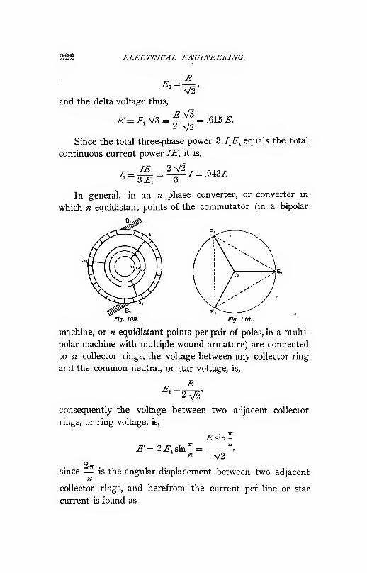
222 ELECTRICAL ENGINEERING.
E^1 =
V2'and the delta voltage thus,
'2 V2
Since the total three-phase power 3 I^E^ equals the total
cdntinuous current power IE, it is,
IE 2 V2^^~-6E^~ 3
7 =.9437.
In general, in an n phase converter, or converter in
which n equidistant points of the commutator (in a bipolar
Fig. 109. Fig. 110.
machine, or n equidistant points per pair of poles, in a multi-
polar machine with multiple wound armature) are connected
to n collector rings, the voltage between any collector ring
and the common neutral, or star voltage, is,
consequently the voltage between two adjacent collector
rings, or ring voltage, is,
IT
E'=2EiSm-E sin -
V2
since — is the angular displacement between two adjacentn
collector rings, and herefrom the current per line or star
current is found as

SYNCBJiONOUS CONVERTERS. 223
/i=2 V2/
and the current flowing from line to line, or from collector
ring to adjacent collector ring, or ring current,
/' = V2/
n X sin -n
As seen in the preceding, in the single-phase converter
consisting of a closed-circuit armature tapped at two equi-
distant points to the two collector rings, the alternating
voltage is —- times the direct current voltage, and the alter-
V2 •
nating current V2 times the direct current. While such an
arrangement of single-phase converter is the simplest, re-
quiring only two collector rings, it is undesirable especially
for larger machines, on account of the great total, and
especially local PR heating in the armature conductors, as
will be shown in the following, and due to the waste of
E.M.F., since in the circuit from collector ring to collector
ring the E.M.F.'s induced in the coils next to the leads are
"wholly or almost wholly opposite to each other.
The arrangement which I have called the " Two Circuit
Single-phase Converter," and which is diagrammatically
Fig. 111.'
shown in Fig. Ill, is therefore preferable. The step-down
transformer T contains two independent secondary coils Aand B, of which the one A feeds into the armature over
224 ELECTRICAL ENGINEERING.
conductor rings D^ D^ and leads «i a^, the other B, over
collector rings D^ D^ and leads a^ a^, so that the two circuits
«j flj and «5 a^ are in phase with each other, and each spreads
over 120° arc instead of 180° arc as in the single circuit
single-phase converter.
In consequence thereof, in the two circuit single-phase
converter the alternating induced E.M.F. bears to the con-
tinuous current E.M.F. the same relation as in the three-
phase converter, that is,
E, = --^.E = .&12E,2 V2
and from the equality of alternating and direct current
power,
2/1^1 = /^,
it follows, that each of the two single-phase supply currents
is,
/'=^/ = .8177.
As seen, in this arrangement, one-third of the armature,
from «i to «3 and from a^ to a^, carries the direct current
only, the other two-thirds, from a^ to a^ and from a^ to a^ the
differential current.
A six-phase converter is usually fed from a three-phase
system by three transformers. These transformers can
either have each one secondary coil only, of twice the star
Eor F voltage, = — which connects with its two terminals
V2two collector rings leading to two opposite points of the
armature, or, as usually preferred, to insure more uniform
distribution of currents, each of the step-down transformers
contains two independent secondary coils, and each of the
two sets of secondary coils is connected in three-phase delta
or Y, but the one set of coils reversed with regard to each
other, thus giving two three-phase systems which join to a
six-phase system.

SYNCHRONOUS CONVERTERS. 225
For further arrangements of six-phase transformation,
see "Theory and Calculation of Alternating Current Phe-
nomena," third edition, Chapter XXIX.Table No. 1 gives, with the direct current voltage and
direct current as unit, the alternating voltages and currents
of the different converters.

226 ELECTRICAL EA<^JJVEEJiINC
The ratio between the difference of potential at the com-
mutator brushes and that at the collector rings of the con-
verter usually differs somewhat from the theoretical ratio,
due to the E.M.F. consumed in the converter armature, and
in machines converting from alternating to continuous cur-
rent, also due to the shape of impressed wave.
When converting from alternating to direct current,
under load the difference of potential at the commutator
brushes is le^s than the induced direct current E.M.F., and
the induced alternating E.M.F. less than the impressed, due
to the voltage consumed by the armature resistance.
If the current in the converter is in phase with the im-
pressed E.M.F., armature self-induction has little effect
;
but reduces the induced alternating E.M.F. below the im-
pressed with a lagging, and raises it with a leading current,
in the same way as in a synchronous motor.
Thus in general the ratio of voltages varies somewhat
with the load and with the phase relation, and with constant
impressed alternating E.M.F. the difference of potential at
the commutator brushes decreases with increasing load,
decreases with decreasing excitation (lag), and increases with
increasing excitation (lead).
When converting from direct to alternating current the
reverse is the case.
The direct current voltage stands in definite proportion
only to the maximum value of the alternating voltage (being
equal to twice the maximum star voltage), but to the effective
value (or value read by voltmeter) only in so far as the latter
depends upon the former, being = — maximum value with aV2
sine wave.
Thus with an impressed wave of E.M.F. giving a dif-
ferent ratio of maximum to effective value, the ratio between
direct current and alternating current voltage is changed in
the same proportion as the ratio of maximum to effective.
> Thus, for instance, with a flat-topped wave of impressed

SYNCHRONOUS CONVERTERS. 22T
E.M.F., the maximum value of alternating impressed E.M.F.and thus the direct current voltage depending thereupon,
are lower than with a sine wave of the same effective value,
while with a peaked wave of impressed E.M.F. they are
higher, by as much as 10% in extreme cases.
In determining the wave shape of impressed E.M.F.at the converter terminals, not only the wave of induced
generator E.M.F., but also that of the converter induced
E.M.F., or counter E.M.F., may be instrumental. Thus,
with a converter connected directly to a generating system
of very large capacity, the impressed E.M.F. wave will be
practically identical with the generator wave, while at the
terminals of a converter connected to the generator over
long lines with reactive coils and inductive regulators inter-
posed, the wave of impressed E.M.F. may be so far modi-
fied by that of the counter E.M.F. of the converter, as
to resemble the latter much more than the generator wave,
and thereby the ratio of conversion may be quite different
from that corresponding to the generator wave.
Furthermore, for instance, in three-phase converters fed
by ring or delta connected transformers, the Y or star
E.M.F. at the converter terminals, which determines the
direct current voltage, may differ from the Y or star
E.M.F. impressed by the generator, by containing different
third and ninth harmonics, which cancel when compound-
ing the Y voltages to the delta voltage, and give identical
delta voltages, as required.
Hence, the ratios of E.M.F.'s given in paragraph 2 have
to be corrected by the drop of voltage in the armature, and
have to be multiplied by a factor which is V2 times the ratio
of effective to maximum value of impressed wave of star
E.M.F. (V2 being the ratio of maximum to eifective of the
sine wave on which the ratios in paragraph 2 were based).
With an impressed wave differing from sine shape, a
current of higher frequency, but generally of negligible
magnitude, flows through the converter armature, due to

228 ELECriilCAL ENGINEERING.
the difference between impressed and counter E.M. F.
wave.
IV. Armature Current and Heating.
The current flowing in the armature conductors of a
converter is the difference between the alternating current
input and the direct current output.
In Fig. 112, a.^, a^, are two adjacent leads connected with
the collector rings D^, D^ in an «-phase converter. The
alternating E.M.F. between a^
and «2' ^"^^ \S\M^ the alter-
nating energy current flowing
in the armature section be-
tween (7j and a^ will reach a
maximum when this section is
midway between the brushes
By and B^, as shown in Fig.
112.
The direct current in every armature coil reverses at
the moment when the the coil passes under brush B^ or
B^ thus is a rectangular alternating current as shown in
Fig. 113 as /. At the moment when the alternating energy
Fig. 113.
current is a maximum, an armature coil d midway between
two adjacent alternating leads «i and a^ is midway between
the brushes B^^ and B^, as in Fig. 112, and is thus in the
middle of its rectangular continuous current wave, and con-
sequently in this coil the alternating energy and the rec-
tangular direct current are in phase with each other, but

i'YNCHRONO US CONVEX TE/iS. 229
opposite, as shown in Fig. 113 as I^ and /, and the actual
current is their difference, as shown in Fig. 114.
In successive armature coils, the direct current reverses
successively. That is, the rectangular currents flowing in
successive armature coils are successively displaced in phase
Fig. 114.
from each other; and since the alternating current is the
same in the whole section a^ a^, and in phase with the rec-
tangular current in the coil d, it becomes more and more
out of phase therewith when passing from coil d towards «i
or «2, as shown in Figs. 115, 116, 117, and 118, until the
maximum phase displacement between alternating and rec-
tangular current is reached at the alternating leads a.^ and
a^, and is equal to -
Thus, if .£ = direct voltage, and T = direct current, in
an armature coil displaced by angle u from the position d,
midway between two adjacent leads of the «-phase converter,
the direct current is - for the half period from to it, and
the alternating current is,
V2/' sin (<^ — ft)).
where,
/'= /V2
n sin -n
is the effective value of the alternating current.
actual current in this armature coil is,
^= v'2-^'sin(<^- w)-2
^/^ 4sin(.^-ft))J I
«sin^i
Thus, the

230 ELECTRICAL ENGINEERING.
and its effective value,
i « sin - I
I. n )
^ / 8 ^ 16 cos u)
= 2\l—
d<l>
+ 1-nir sin -
n

SYNCHRONOUS CONVERTERS. 231
Since ^ is the current in the armature coil of a direct cur-
rent generator of the same output, we have,
8 16 cos 0)
«^ Sin" - «7r sin -n n
the ratio of the energy loss in the armature coil resistance of
the converter, to that of the direct current generator of the
same output, and thus the ratio of coil heating.
This ratio is a maximum at the position of the alternat-
ing leads, M = - , and is,
o 16 cos
-
8 ny,„= hi
tr sm'^ - ntr sin -n' n
It is a minimum for a coil midway between adjacent
alternating leads, w — 0, and is,
8 , 1670= -+1
•
n'- sin" - «ir sin -n n
Integrating over <o from (coil d) to -, that is, over the
whole phase or section (7j a^, we have.
TT
tf sin-^ -n
+ l-^>
the ratio of the total energy loss in the armature resistance
of an «-phase converter to that of the same machine as
direct current generator at the same output, or the relative
armature heating.
Thus, to get the same energy loss in the armature con-
ductors, and consequently the same heating of the armature,
the current in the converter, and thus its output, can be

232 ELECTRICAL ENGINEERING.
increased in the proportion— over that of the direct cur-vr
rent generator.
The calculation for the two circuit single-phase converter
is somewhat different ; since in this in one-third of the arma-
ture the PR loss is that of the direct current output, and
only in the other two-thirds,— or as arc -^,— the differen-o
tial current flows. Thus in an armature coil displaced byangle w from the center of this latter section, the resultant
current is,
4 = V2/' sin (<^ _ 0,) — -
giving the effective value,
16cos (1),
V n-Jo » ^ 2 V 3 ^^thus the relative heating,
//o\' 11 16
with the minimum value, w =
1^ 1^70
and the maximum value, <" = x;
and the average current heating in two-thirds of the
armature.
IT «/0
^ ^ 11 16 . Xy„ «(i) = ,
—
— sin -ir«-'o 3 IT V3 3
"-«=1.116 IT

SYNCHRONOUS CONVERTERS. 233
in the- remaining third of the armature, r^ = 1, thus the
average,
2r, + rir =
and thus the rating.
Vr
3
: 1.072,
:.97.
By substituting for n in the general equations of cur-
rent heating and rating based thereon, numerical values, weget thus the table,
Type.

234 ELECTRICAL ENGINEERING.
thus its effective value,
''-^m?''"*
-w-8(1+^2 ^ _ 16(l + ycosai)
T^ sin^ - «n- Sin -n n
hence,
, ./o^_ 8(l + ^)' 16a+y)cosco
77 «^ sin* - «7r sm -2 « u
„ ^ 8 8 cos (1) \= y. + 2? \( .
y w"" sin"^ - nir sin - \I. « ;/ ;
Integrated over u> from to —
.
T Jo \^«^sin^^^ /
r'=r(i + 2^)-2^(i-i)
In the two circuit single-phase converter, we have,
/;= /'(l + ?)sin(<^-a.)-/
,^ 8(1 + gf + ?, _ 16(1 + y)cos.
cos CI)
V3
3 ttVS
8(l + ^y + 3 8(1 + ^)^' - 3 -^r
'
r = i + ^'.

SYNCHRONOUS CONVERTERS. 235
Herefrom we get the values for the relative current
heating r', and the corresponding rating —j=, by assuming
q = .04.
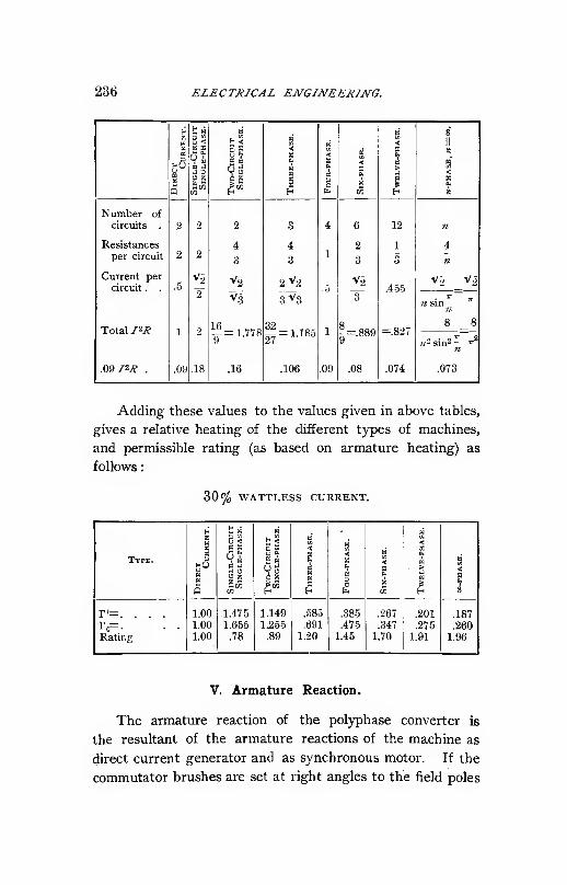
236 ELECTRICAL ENGINEERING.

SYNCHRONOUS CONVERTERS. 237
or without lead or lag, as is usually done in converters, the
direct current armature reaction consists in a polarization
in quadrature behind the field magnetism. The armature
reaction due to the energ)' component of the alternating
current in a synchronous motor consists of a polarization in
quadrature ahead of the field magnetism, which is opposite
to the armature reaction as direct current generator.
Let m = total number of turns on the bipolar armature
of an n = phase converter, / = direct current, then then um-
ber of turns in series between the brushes = -^ , hence the
total armature ampere turns, or polarization = --^. Since,
however, these ampere turns are not unidirectional, but
distributed over the whole surface of the armature, their
resultant is.
And since
_ mlif = ~fr- avg. cos
avg. COS.
.
we have, SF = = direct current polarization of the con-K
verter (or direct current generator) armature.
In an n = phase converter the number of turns per
mphase = — The current per phase or current between
two adjacent leads (ring current) is,
j,^ \/2/
n sin-n
hence ampere turns per phase,
ml'^ ^J2ml
nr sm -

238 ELECTRICAL ENGINEERING.
These ampere turns are distributed over - of the circum-' n
ference of the armature, and their resultant is thus,
ml' '+-
and since,
We have.
{F,= avg. cosn
( « n . IT
avs;. COS. \ = - sm -:
I TT n
"^1— = resultant polarization,
in effective ampere turns, of one phase of the converter.
The resultant M.M.F. of n equal M.M.F.'s of effective
value of fFj, thus maximum value of fFi V2, acting under
equal angles — > and displaced in phase from each other by -n 2-
of a period, or phase angle— , if found thus :
fi
Let ?,= ffiV2 sin [ <^)= one of the M.M.F.s of phase
angle <^ = , acting in the direction w =
That is, the zero point of one of the M.M.F.'s JF^ is taken as
zero point of time <l>, and the direction of this M.M.F. as
zero point of direction w.
The resultant M.M.F. in any direction o is thus,
ff = ^/fF;Cos ( o) + —^j
= ff,y/2^t siu [cl> - ^j cos ^0,- ^j
= ^'i:^'j-(.^ + »-ii^) + sin(.^-o.)|
JF,V2(^. . /, 4/7r'\ . , J= —7j—j2^1 sml<t> + 0) 1 + nsm{<f, — a)}'

SYNCHRONOUS CONVERTERS. 239
and since,
we have,
^z sinI<^ + (0 ^
I
= 0,
jf=,^W2sin(,^-<,);
that is,
The resultant M.M.F. in any direction u, has the phase,
^ = (0,
and the intensity,
thus revolves in space with uniform velocity and con-
stant intensity, in synchronism with the frequency of the
alternating current.
Since in the converter,
^ V2ot/
irn
we have
^, 7nl'5 =
the resultant M.M.F. of the alternating energy current in
the « = phase converter.
This M.M.F. revolves synchronously in the armature of
the converter; and since the armature rotates at synchronism,
the resultant M.M.F. stands still in space, or with regard
to the field poles, in opposition to the direct current polariza-
tion. Since it is equal thereto, it follows, that the resultant
armature reactions of the direct current and of the cor-
responding alternating energy current in the synchronous
converter are equal and opposite, thus neutralize each other,
and the resultant armature polarization equals zero. The
same is obviously the case in an " Inverted Converter " ;
that is, a machine changing from direct to alternating
current.
The conditions in a single-phase converter are different,

240 ELECTRICAL ENGINEERING.
however. At the moment when the alternating current — 0,
the full direct current reaction exists. At the moment
when the alternating current is a maximum, the reaction is
the difference between that of the alternating and of the
direct current ; and since the maximum alternating current
in the single-phase converter equals twice the direct current,
at this moment the resultant armature reaction is equal but
opposite to the direct current reaction.
Hence, the armature reaction oscillates with twice the
frequency of the alternating current, and with full intensity,
and since it is in quadrature with the field excitation, tends
to shift the magnetic flux rapidly across the field poles, and
thereby tends to cause sparking and energ}' losses. This
oscillating reaction is, however, essentially reduced by the
damping effect of the magnetic field structure.
Since in consequence hereof the commutation of the
single-phase converter is not as good as of the polyphase
converter, in the former usually voltage commutation has to
be resorted to ; that is, the brushes shifted from the position
midway between the field poles ; and in consequence thereof,
the continuous current ampere turns inclosed by twice the
angle of lead of the brushes act as a demagnetizing armature
reaction, and require a corresponding increase of the field
excitation under load.
Since the resultant main armature reactions neutralize
each other in the polyphase converter, there remain only—1st. The armature reaction due to the small energy
current required to rotate the machine ; that is, to cover the
int'ernal losses of power, which is in quadrature with the
field excitation or distorting, but of negligible magnitude.
2d. The armature reaction due to the wattless com-
ponent of alternating current where such exists, and
3d. An effect of oscillating nature, which may be called
a " Higher Harmonic of Armature Reaction."
The direct current, as rectangular alternating current in
the armature, changes in phase from coil to coil, while the

SYNCHONROUS CONVERTERS. 241
alternating current is the same in a whole section of the
armature between adjacent leads.
Thus while the resultant reactions neutralize, a local
effect remains which in its relation to the magnetic field
oscillates with a period equal to the time of motion of the
armature through the angle between adjacent alternating
leads ; that is, double frequency in a single-phase converter
(in which it is equal in magnitude to the direct current
reaction, and is the oscillating armature reaction discussed
above), triple frequency in a three-phase converter, and
quadruple frequency in a four-phase converter.
The amplitude of this oscillation in a polyphase con-
verter is small, and its influence upon the magnetic field is
usually negligible, due to the damping effect of the field
spools, which act like a short circuited winding for an oscil-
lation of magnetism.
A polyphase converter on unbalanced circuit can be con-
sidered as a combination of a balanced polyphase and a
single-phase converter ; and since even single-phase con-
verters operate quite satisfactorily, the effect of unbalanced
circuits on the polyphase converter is comparatively small,
within reasonable limits.
Since the armature reaction of the direct current and
of the alternating current in the converter neutralize each
other, no change of field excitation is required in the con-
verter with changes of load.
Furthermore, while in a direct current generator the
armature reaction at given field strength is limited by the
distortion of the field caused thereby, this limitation does
not exist in a converter; and a much greater armature
reaction can be safely used in converters than in direct
current generators, the distortion being absent in the former.
Since the armature heating is relatively small, the prac-
tical limit of overload capacity of a converter is that due to
the commutator, and is usually far higher than in a direct
current generator, since the distortion of field, which causes

242 ELECTRICAL ENGINEERING.
sparking on the commutator under overloads in a direct
current generator, is absent in a converter.
The theoretical limit of overload— that is, the overload
at which the converter as synchronous motor drops out of
step and comes to a standstill— is far beyond reach at steady
frequency and constant impressed alternating voltage, while
on an alternating circuit of pulsating frequency or drooping
voltage it obviously depends upon the amplitude and period
of the pulsation of frequency and on the drop of voltage.
VI. Wattless Currents and Compounding.
Since the polarization due to the alternating energy cur-
rent as synchronous motor is in quadrature ahead of the field
magnetization, the polarization or magnetizing effect of the
lagging component of alternating current is in phase, that of
the leading component of alternating current in opposition to
the field magnetization. That is, in the converter no mag-
netic distortion exists, and no armature reaction at all if the
current is in phase with the impressed E.M.F., while the arma-
ture reaction is demagnetizing with a leading, magnetizing
with a lagging current.
Thus if the alternating current is lagging, the field ex-
citation at the same impressed E.M.F. has to be lower, and
if the alternating current is leading, the field excitation has
to be higher, than required with the alternating current in
phase with the E.M.T". Inversely, by raising the field ex-
citation a leading current, or by lowering it a lagging current,
can be produced in a converter (and in a synchronous motor).
Since the alternating current can be made magnetizingor demagnetizing according to the field excitation, at con-stant impressed alternating voltage, the field excitation of
the converter can be varied through a wide range without
noticeably affecting the voltage at the commutator brushes;
and in converters of high armature reaction and relatively
weak field full-load and over-load can be carried by the

SYNCHRONOUS CONVERTERS. 243
machine without any field excitation whatever, that is, byexciting the field by armature reaction by the lagging
alternating current. Such converters without field excila-
\ion, or " Reaction Converters," must always run with moreor less lagging current, that is, give the same reaction on
the line as induction motors, which, as known, are far more
objectionable than synchronous motors in their reaction on
the alternating system.
Conversely, however, at constant impressed alternating
voltage the direct current voltage of a converter cannot be
varied by varying the field excitation (except by the very
small amount due to the change of the ratio of conversion),
but a change of field excitation merely produces wattless
currents, lagging or magnetizing with a decrease, leading or
demagnetizing with an increase of field excitation. Thus to
vary the continuous current voltage of a converter, the im-
pressed alternating voltage has to be varied. This can be
done either by potential regulator or compensator, that is,
transformers of variable ratio of transformation, or by the
effect of wattless currents on self-induction. The latter
method is especially suited for converters, due to their ability
of producing wattless currents by change of field excitation.
The E.M.F. of self-induction lags 90° behind the current.
Thus if the current is lagging 90° behind the impressed
E.M.F., the E.M.F. of self-induction is 180° behind, or in
opposition to the impressed E.M.F., and thus reduces it. If
the current is 90° ahead of the E.M.F., the E.M.F. of self-
induction is in phase with the impressed E.M.F., thus adds
itself thereto and raises it. Thus if self-induction is inserted
into the lines between converter and constant potential gen-
erator, and a wattless lagging current is produced by the
converter by a decrease of its field excitation, the E.M.F. of
self-induction of this lagging current in the line lowers the
alternating impressed voltage at the converter and thus its
direct current voltage ; and if a wattless leading current is
produced by the converter by an increase of its field excita-
244 ELECTRICAL ENGINEERING.
tion, the E.M.F. of self-induction of this leading current
raises the impressed alternating voltage at the converter and
thus its direct current voltage.
In this manner, by self-induction in the lines leading to
the converter, its voltage can be varied by a change of field
excitation, or conversely its vojtage maintained constant at
constant generator voltage or even constant generator excita-
tion, with increasing load and thus increasing resistance drop
in the line ; or the voltage can even be increased with in-
creasing load, that is, the system over-compounded.
The change of field excitation of the converter with
changes of load can be made automatic by the combination
of shunt and series field, and in this manner a converter can
be compounded or even over-compounded similarly to a
direct current generator. While the effect is the same, the
action, however, is different ; and the compounding takes
place not in the machine as with a direct current generator,
but in the alternating lines leading to the machine, in which
self-induction becomes essential.
VII. Starting,
The polyphase converter is self-starting from rest ; that
is, when connected across the polyphase circuit it starts, ac-
celerates, and runs up to complete synchronism. TheE.M.F. between the commutator brushes is alternating in
starting, with the. frequency of slip below synchronism.
Thus a direct current voltmeter or incandescent lamps con-
nected across the commutator brushes indicate by their
beats the approach of the converter to synchronism. Whenstarting, the iield circuit of the converter has to be opened
or at least greatly weakened. The starting of the polyphase
converter is essentially a hysteresis effect and, entirely so in
machines with laminated field poles, while in machines with
solid magnet poles, induced currents in the latter contribute
to the starting torque, but at the same time reduce the mag-
SYNCHRONOUS CONVERTERS. 245
netic starting flux by their demagnetizing effect. The torque
is produced by the attraction between the alternating cur-
rents of the successive phases upon the remanent magnetism
or induced currents produced by the preceding phase. It
necessarily is comparatively weak, and from full-load to twice
full-load current is required to start from rest without load.
Obviously, the single-phase converter is not self-starting.
At the moment of starting, the field circuit of the converter
is in the position of a secondary to the armature circuit as
primary; and since in general the number of field turns is
very much larger than the number of armature turns, ex-
cessive E.M.F.'s may be induced in the field, reaching
frequently 4000 to 6000 volts, which have to be taken care
of by some means, as by breaking the field circuit into
sections. As soon as synchronism is reached, which usually
takes from a few seconds to a minute or more, the field
circuit is closed, and the load put on the converter. Obvi-
ously, while starting, the direct current side of the converter
must be open circuited, since the E.M.F. between commu-
tator brushes is alternating until synchronism is reached.
When starting from the alternating side, the converter
can drop into synchronisrri at either polarity ; but its polarity
can be reversed by strongly exciting the field in the right
direction by some outside source, as another converter, etc.
Since when starting from the alternating side the con-
verter requires a very large and, at the same time, lagging
current, it is preferable wherever feasible to start it from
the direct current side as direct current motor. This can
be done when connected to storage battery or direct current
generator. When feeding into a direct current system
together with other converters or converter stations, all but
the first converter can be started from the continuous cur-
rent side by means of rheostats inserted into the armature
circuit.
To avoid the necessity of synchronizing the converter,
by phase lamps, with the alternating system in case of

246 ELECTRICAL ENGINEERING.
Starting by direct current (which operation may be difficult
where the direct current voltage fluctuates, owing to heavy
fluctuations of load, as railway systems), it is frequently
preferable to run the converter up to or beyond synchronism
by direct current ; then cut off from the direct current,
open the field, and connect it to the alternating system,
thus bringing it into step by alternating current.
VIII. Inverted Converters.
Converters may be used to change either from alter-
nating to direct current or as " Inverted Converters " from
direct to alternating current. While the former use is by
far more frequent, sometimes inverted converters are de-
sirable. Thus in low-tension direct current systems, an
outlying district may be supplied by converting from direct
to alternating, transmitting as alternating, and then recon-
verting to direct current. Or in a station containing direct
current generators for short distance supply and alternators
for long distance supply, the converter may be used as the
connecting link to shift the load from the direct to the
alternating generators, or inversely, and thus be operated
either way according to the distribution of load on the
system.
When converting from alternating to direct current, the
speed of the converter is rigidly fixed by the frequency,
and cannot be varied by its field excitation, the variation of
the latter merely changing the phase relation of the alter-
nating current. When converting, however, from direct to
alternating current as only source of alternating current,
that is, not running in multiple with engine or turbine
driven alternating current generators, the speed of the con-
verter as direct current motor depends upon the field
strength, thus it increases with decreasing and decreases
with increasing field strength. As alternating current gen-
erator, however, the field strength depends upon the intensity
SYNCHRONOUS CONVERTERS. 247
and phase relation of the alternating current, lagging current
reducing the field strength, and thus increasing speed and
frequency, and leading current increasing the field strength,
and thus decreasing speed and frequency.
Thus, if a load of lagging current is put on an inverted
converter, as, for instance, by starting a converter thereby
from the alternating side, the demagnetizing effect of the
alterpating current reduces the field strength, and causes
the converter to increase in speed and frequency. An in-
crease of frequency, however, may increase the lag of the
current, and thus its demagnetizing effect, and thereby still
further increase the speed, so that the acceleration maybecome so rapid as to be beyond control by the field rheostat,
and endanger the machine. Hence, inverted converters
have to be carefully watched, especially when starting other
converters from them ; and some absolutely positive device
is necessary to cut the inverted converter off the circuit
entirely as soon as its speed exceeds the danger limit. The
relatively safest arrangement is separate excitation of the
inverted converter by an exciter mechanically driven thereby,
since an increase of speed increases the exciter voltage at a
still higher rate, and thereby the excitation of the converter,
and thus tends to check its speed.
This danger of racing does not exist if the inverted
converter operates in parallel with alternating generators,
provided that the latter and their prime movers are of such
size that they cannot be carried away in speed by the
converter. In an inverted converter running in parallel
with alternators, the speed is not changed by the field exci-
tation, but a change of the latter merely changes the phase
relation of the alternating current supplied by the converter.
That is, the converter receives power from the direct current
system, and supplies power into the alternating system, but
at the same time receives wattless current from the alter-
nating system, lagging at under-excitation, leading at over-
excitation, and can in the same way as an ordinary converter

248 ELECTRICAL ENGINEERING.
or synchronous motor be used to compensate for wattless
currents in other parts of the alternating system.
IX. Double Current Generators.
Similar in appearance to the converter, which changes
from alternating to direct current, and to the inverted con-
verter, which changes from direct to alternating current, is
the double current generator ; that is, a machine driven by
mechanical power and producing direct current as well as
alternating current from the same armature, which is con-
nected to commutator and collector rings in the same way
as in the converter. Obviously the use of the double cur-
rent generator is limited to those sizes and speeds at which
a good direct current generator can be built with the same
number of poles as a good alternator ; that is, low frequency
machines of large output and relatively high speed, while
high frequency slow speed double current generators are
undesirable.
The essential difference between double current gen-
erator and converter is, however, that in the former the
direct current and the alternating current are not in oppo-
sition as in the latter, but in the same direction, and the
resultant armature polarization thus the sum of the armature
polarization of the direct current and of the alternating
current.
Since at the same output and the same field strength,
the armature polarization of the direct current and that of
the alternating current is the same, it follows that the resul-
tant armature polarization of the double current generator is
proportional to the load, regardless of the proportion in which
this load is distributed between the alternating and direct
current side. The heating of the armature due to its resist-
ance depends upon the sum of the two currents ; that is,
upon the total load on the machine. Hence, the output of
the double current generator is limited by the current heat-

SYNCHRONOUS CONVERTERS. 249
ing of the armature, and by the field distortion due to the
armature reaction, in the same way as in a direct current
generator or alternator, and is consequently much less thanthat of a converter.
In double current generators, owing to the existence of
armature reaction and consequent field distortion, the com-
mutator brushes are more or less shifted against the neutral,
and the direction of the continuous current armature polar-
ization is thus shifted against the neutral by the same angle
as the brushes. The direction of the alternating current
armature polarization, however, is shifted against the neutral
by the angle of phase displacement of the alternating cur-
rent. In consequence thereof, the reaction upon the field
of the two parts of the armature polarization, that due
to the continuous current and that due to the alternating
current, are usually different. The reaction on the field of
the direct current load can be overcome by a series field.
The reaction on the field of the alternating current load
when feeding converters, can be compensated for by a
change of phase relation, by means of a series field on the
converter, with self-induction in the alternating lines.
Thus, a double current generator feeding on the alter-
nating side converters, can be considered as a direct current
generator in which a part of the commutator, with a cor-
responding part of the series field, is separated from the
generator and located at a distance, connected by alternating
leads to the generator. Obviously, automatic compounding
of a double current generator is feasible only if the phase
relation of the alternating current changes from lag at no
load to lead at load, in the same way as produced by a com-
pounded converter. Otherwise, rheostatic control of the
generator is necessary. This is, for instance, the case if the
voltage of the double current generator has to be varied to
suit the conditions of its direct current load, and the voltage
of the converter at the end of the alternating lines varied to
suit the conditions of load at the receiving end, independent

250 ELECTRICAL ENGINEERING.
of the voltage at the double current generator, by means of
alternating potential regulators or compensators.
Compared with the direct current generator, the field of
the double current generator must be such as to give a much
greater stability of voltage, owing to the strong demagne-
tizing effect which may be exerted by lagging currents on
the alternating side, and may cause the machine to lose its
excitation altogether. For this reason it is frequently prefer-
able to separately excite double current generators.
X. Conclusion.
Of the types of machines, converter, inverted converter,
and double current generator, sundry combinations can be
devised with each other and with synchronous motors, alter-
nators, direct current motors and generators. Thus, for
instance, a converter can be used to supply a certain amount
of mechanical power as synchronous motor. Tn this case
the alternating current is increased beyond the value cor-
responding to the direct current by the amount of cur-
rent giving the mechanical power, and the armature reactions
do not neutralize each other, but the reaction of the alter-
nating current exceeds that of the direct current by the
amount corresponding to the mechanical load. In the same
way the current heating- of the armature is increased. Aninverted converter can also be used to supply some mechani-
cal power. Either arrangement, however, while quite fea-
sible, has the disadvantage of interfering with automatic
control of voltage by compounding.
Double current generators can be used to supply morepower into the alternating circuit than is given by their
prime mover, by receiving power from the direct current
side. In this case a part of the alternating power is gene-
rated from mechanical power, and the other converted from
direct current power, and the machine combines the features
of an alternator with that of an inverted converter. Con-

SYNCHRONOUS CONVERTERS. 251
versely, when supplying direct current power and receiving
mechanical power from the prime mover and electric powerfrom the alternating system, the double current generator
combines the features of a direct current generator and a
converter. In either case the armature reaction, etc., is the
sum of those corresponding to the two types of. machines
combined.
The use of the converter to change from alternating to
alternating of a different phase, as, for instance, when using
a quarter-phase converter to receive power by one pair of
its collector rings from a single-phase circuit, and supplying
from its other pair of collector rings the other phase of a
quarter-phase system, or a three-phase converter on a single-
phase system supplying the third wire of a three-phase
system from its third collector ring, is outside the scope
of this treatise, and is, moreover, of very little importance,
since induction or synchronous motors are superior in this
respect.
APPENDIX.
Direct Current Converter.
If n equidistant pairs of diametrically opposite points of a
commutating machine armature are connected to the ends of
n compensators or auto-transformers, that is, electric circuits
interlinked with a magnet circuit, and the centers of these
compensators connected with each other to a neutral point,
as shown diagrammatically in Fig. 119 for « = 3, this neutral
is equidistant in potential from the two sets of commutator
brushes, and such a machine can be used as continuous cur-
rent converter, to transform in the ratio of potentials 1 : 2 or
2 : 1 or 1 : 1, in the latter case transforming power from one
side of a three-wire system to the other side.
Obviously either the n compensators can be stationary
and connected to the armature by In collector rings, or the
compensators rotated with the armature and their common

262 ELECTRICAL ENGINEERING.
neutral connected to the external circuit by one collector
ring.
The distribution of potential and of current in such a
direct current converter is shown in Fig. 120 for » = 2, that
is, two compensators in quadrature.
Fig. 119.
i.

SYNCHRONOUS CONVERTERS. 253
Neglecting losses in converter and compensator, the cur-
rents in the two sets of commutator brushes are equal and of
the same direction, that is, both outgoing or both inflowing,
and opposite to the current in the neutral. That is, twoequal currents i enter the commutator brushes and issue as
current 2/ from the neutral, or inversely.
From the law of conservation of energy it follows that
the current li entering from the neutral divides in 2«
equal and constant branches of direct current, -' in then
In compensator sections, and hence enters the armature, to
issue as current i from each of the commutator brushes.
In reality the current in each compensator section is
—i-4V2 cos ( <A — a> \- a.
n \ n
where ?'„ is the exciting current of the magnetic circuit of
the compensator, and i* the angle of hysteretic advance of
phase. At the commutator the current on the motor side
is larger than the current on the generator side, by the
amount required to cover the losses of power in converter
and compensator.
In Fig. 120 the positive side of the system is generator,
the negative side motor. This machine can be considered
as receiving current i at voltage e from the negative side of
the system, and transforming it into current / at voltage e
on the positive side of the system, or it can be considered
as receiving current i at voltage 1c from the system, and
transforming into current li at the voltage e on the positive
side of the system, or of receiving current 2? at voltage e
from the negative side, and returning current i at voltage 1e.
In either case the direct current converter produces a dif-
ference of power of 2?V between the two sides of the three-
wire system.
The armature reaction of the currents from the generator
side of the converter is equal but opposite to the armature-
reaction of the corresponding currents entering the motor

2u4 ELECTRICAL ENGINEERING.
side, and the motor and generator armature reactions thus
neutralize each other, as in the synchronous converter, that
is, the resultant armature reaction of the continuous current
converter is practically zero, or the only remaining armature
reaction is that corresponding to the relatively small current
required to rotate the machine, that is, to supply the internal
'^-^^^^^^^^WW^^^^MMTM
BJt D^
'
iii|
6ilji!uiidilj6Lljiljiijiijiljiijiljbliii)ii)ii)diilii!iii^6di6^^^
Fig. 121.
' losses in the same. Obviously it also remains the armature
reaction of the current supplying the electric power trans-
formed into mechanical power, if the machine is used simul-
taneously as motor, as 'for driving a booster connected into
the system to produce a difference between the voltages of
the two sides, or the armature reaction of the currents gen-
erated from mechanical power if the machine is driven as
generator.
While the currents in the armature coils are more or less
sine waves in the alternator, rectangular reversed currents
in the direct current generator or motor, and distorted

SYNCHRONOUS CONVERTERS. 255
triple frequency currents in the synchronous converter, the
currents in the armature coils of the direct current con-
verter are triangular double frequency waves.
Let Fig. 121 represent a dfevelopment of a direct cur-
rent converter with brushes B^ and B.^^, and C one compen-
__,--

256 ELECTRICAL ENGINEERING.
grows less and becomes zero when b^ coincides with B,^, or
half a cycle after its coincidence with B.^. That is, the cur-
rent in coil «! has the triangular form shown as Zj in Fig. 122,
changing twice per period from to i. It is shown negative,
since it flows against the direction of rotation of the arma-
ture. In the same way we see that the current in the coil a'
,
adjacent ahead of the lead b.^, has a shape shown as i' in Fig.
16. The current in coil «„ midway between two commutator
leads has the form ?'„, and in general the current in any
armature coil a„ distant by angle w from the midway position
a^, has the form i^ Fig. 122.
All the currents become zero at the moment where the
compensator leads b^^ coincide with the brushes B.^B^ and
change by i at the moment where their respective coils pass
a commutator brush. Thus the lines A and A' in Fig. 128
A' A A'
^^^^^""^^

SYNCHRONOUS CONVERTERS. 257
shape shown in Fig. 124 for « = 3. That is, each compen-sator gives a set of slanting lines A^A\, A^\, A^A\, and all
Fig. 124.
the branch currents Zj ^ tg, superposed, give a resultant
current 4, which changes by i in the moment the coil passes
t
the brush. 4 varies between the extreme values -^(2/— 1)
and (2/ +1), if the armature coil is displaced from the
midway position between two adjacent compensator leads by
angle <d, and/ = . / varies between — ^^ and+j^.
Thus the current in an armature coil in position p = -
can be denoted in the range from p to 1 +/, or wto ir +<d,
by
whereTT

258 ELECTRICAL ENGINEERING
The effective value of this current is,
i=sly^^\idx
Since in the same machine as direct current generator
at voltage 2 e and current i, the current per armature
coil is — , the ratio of current is,
2
and thus the relative Pr loss or the heat developed in the
armature coil,
with a minimum,
and a maximum.
(f)
/ = 0, 70 = J.
_ 1 . 1 _ 3 + «"
'>''""3"^^~~3^'
The mean heating or Pr of the armature is found by inte-
grating over 7 from1 1
^=-2^ ^°^= + 2^^
as
r = «\ ^ ydj>
^ 2n
_ 1 1 _ 1 + «'
~3"'"3«^~3«''
This gives the following table, for the direct current con-
verter, of minimum current heating, y^, .in the coil mid-^
way between adjacent commutator leads, maximum current
heating, )/„, in the coil adjacent to the commutator lead;

SYNCHRONOUS CONVERTERS. 259
mean current heating, r, and rating as based on mean cur-
rent heating in the armature, -^
:
Vr
DIRECT CURRENT CONVERTER I'-r RATING.
No. of compensators, n=
Minimum current heating,
Maximum current heating,
/ = + —
,
T" =n
Mean current heating,
r =
Rating,1
d. c.
gen.
1.225 1.549 1.643 1.C81
:+-
h^-.
il+7«2 i.7.:2
As seen, the output of the direct current converter
is greater than that of the same machine as generator.
Using more than three compensators offers very little
advantage, and the difference between three and two com-
pensators is comparatively small, also, but the difference
between two and one compensator, especially regarding the
local armature heating, is considerable, so that for mostpractical purposes a two-compensator converter would bepreferable.
The number of compensators used in the direct cur-
rent converter has a similar effect regarding current dis-
tribution, heating, etc., as the number of phases in the
synchronous converter.
Obviously these relative outputs given in above table re-
fer to the armature heating only. Regarding commutation,
the total current at the brushes is the same in the converter
as in the generator, the only advantage of the former thus
the better commutation due to the absence of armature
reaction.

260 ELECTRICAL ENGINEERING.
The limit of output set by armature reaction and corre-
sponding field excitation in a motor or generator obviously
does not exist at all in a converter. It follows herefrom
that a direct current motor or generator does not give the
most advantageous direct current converter, but that in the
direct current converter, just as in the synchronous con-
verter, it is preferable to proportion the parts differently, in
accordance with above discussion, as, for instance, to use
less conductor section, a greater number of conductors in
series per pole, etc.

INDUCTION MACHINES. ' 261
D. INDUCTION MACHINES.
I. General.
The direction of rotation of a direct current motor,
whether shunt or series wound, is independent of the direc-
tion of the current supplied thereto. That is, when revers-
ing the current, in a direct current motor the direction of
rotation remains the same. Thus theoretically any con-
tinuous current motor should operate also with alternating
currents. Obviously in this case not only the armature, but
also the magnetic field of the motor must be thoroughly
laminated to exclude eddy currents, and care taken, that the
current in iield and in armature reverses simultaneously.
The simplest way of fulfilling the latter condition is obviously
to connect field and armature in series as alternating current
series motor. Such motors have been used to a limited ex-
tent. Their main objection is, however, the excessive self-
induction introduced by the alternating field excitation, and
the consequently low power factor, and also the vicious
sparking at the commutator. Besides, as series motor the
speed is not constant, but depends upon the load.
The shunt motor on an alternating circuit has the ob-
jection that in the armature the current should be energy
current, thus in phase with the E.M.F., while in the field
the current is lagging nearly 90°, as magnetizing current.
Thus field and armature would be out of phase with each
other. To overconie this objection the field may be excited
from a separate E.M.F. differing 90° in phase from that
supplied to the armature. That is, the armature of the
motor is fed by one, the field by the other phase of a quarter-

262 ELECTRICAL ENGINEERING.
phase system, and thus the current in the armature brought
approximately in phase with the magnetic flux of the field.
Such an arrangement obviously loads the two phases of
the system unsymmetrically, the one with the armature
energy current, the other with the lagging field current. Tobalance the system two such motors may be used simultane-
ously and combined in one structure, the one receiving
energy current from the first, magnetizing current from the
second phase, the second motor receiving rragnetizing cur-
rent from the first and energy current from the second
phase.
The objection of the vicious sparking of the commutator
can be entirely overcome by utilizing the alternating feature
of the current ; that is, instead of leading the current into
the armature by commutator and brushes, producing it
therein by electro-magnetic induction, by closing the arma-
ture conductors upon themselves and surrounding the
armature by an inducing coil at right angles to the field
exciting coil.
Such motors have been built, consisting of two struc-
tures each containing a magnetizing circuit acted upon by
one phase, and an energy circuit inducing a closed circuit
armature and excited by the other phase of a quarter-phase
system.
Going still a step further, the two structures can be com-
bined into one by having er.ch of the two ceils fulfill the
double function of magnetizing the field and inducing cui"-
rents in the armature which are acted upon by the mag-
netization produced by the other phase.
Obviously, instead of two phases in quadrature any
number of phases can be used.
This leads us by gradual steps of development from the
continuous current shunt motor to the alternating current
polyphase induction motor.
In its general behavior the alternating current induction
motor is analogous to the continuous current shunt motor.

INDUCTION MACHINES. 263
Like the shunt motor, it operates at approximately constant
magnetic density. It will run at fairly constant speed, slow-
ing down gradually with increasing load. The main differ-
ence IS, that in the induction motor the current is not passed
into the armature by a system of brushes, as in the con-
tinuous current motor, but induced in the armature ; and in
consequence thereof, the primary circuit of the induction
motor fulfills the double function of an exciting circuit
corresponding to the field circuit of the continuous current
machine, and a primary circuit inducing a secondary current
in the armature by electro-magnetic induction.
Since in the armature of the induction motor the cur-
rents are produced by induction from the primary impressed
currents, the induction motor in its electro-magnetic fea-
tures is essentially a transformer ; that is, it consists of a
magnetic circuit or magnetic circuits interlinked with two
electric circuits or sets of circuits, the primary or inducing,
and the secondary or induced circuit. The difference be-
tween transformer and induction motor is, that in the former
the secondary is fixed regarding the primary, and the electric
energy induced in the secondary is made use of, while in the
latter the secondary is mova-ble regarding the primary, and
the mechanical force acting between primary and secondary
is used. In consequence thereof the frequency of the cur-
rents flowing in the secondary of the induction motor differs
from, and as a rule is very much lower than, that of the
currents impressed upon the primary, and thus the ratio of
E.M.F.'s induced in primary and in secondary is not the
ratio of their respective turns, but is the ratio of the product
of turns and frequency.
Taking due consideration of this difference of frequency
between primary and secondary, the theoretical investigation
of the induction motor corresponds to that of the stationary
transformer. The transformer feature of the induction
motor predominates to such an extent that in theoretical
investigation the induction motor is best treated as a trans-

264 ELECTRICAL ENGINEERING.
former, and the electrical output of the transformer corre-
sponds to the mechanical output of the induction motor.
The secondary or armature of the motor consists of two
or more Circuits displaced in phase from each other so as to
offer a closed secondary to the primary circuits, irrespective
of the relative motion. The primary consists of one or
several circuits.
In consequence of the relative motion of the primary and
secondary, the magnetic circuit of the induction motor must
be arranged so that the secondary while revolving does not
leave the magnetic field of force. That means, the magnetic
field of force must be of constant intensity in all directions,
or, in other words, the component of magnetic flux in any
direction in space be of the same or approximately the same
intensity but differing in phase. Such a magnetic field can
either be considered as the superposition of two magnetic
fields of equal intensity in quadrature in time and space, or
it can be represented theoretically by a revolving magnetic
flux of constant intensity, or simply treated as alternating
magnetic flux of the same intensity in every direction.
In the polyphase induction motor this magnetic field is
produced by a number of electric circuits relatively displaced
in space, and excited by currents having the same displace-
ment in phase as the exciting coils have in space.
In the monocyclic motor one of the two superimposed
quadrature fields is excited by the primary energy circuit,
the other by the magnetizing or teaser circuit.
In the single-phase motor one of the two superimposed
magnetic quadrature fields is excited by the primary elec-
tric circuit, the ether by the induced secondary or armature
currents carried into quadrature position by the rotation of
the secondary. In either case, at or near synchronism the
magnetic fields are identical.
The transformer feature being predominant, in theo-
retical investigations of induction motors it is generally
preferable to start therefrom.

INDUCTION MACHINES. 265
The characteristics of the transformer are independent
of the ratio of transformation, other things being equal.
That is, doubling the number of turns for instance, and at
the same time reducing their cross-section to one-half, leaves
the efficiency, regulation, etc., of the transformer unchanged.
In the same way, in the induction motor it is unessential
what the ratio of primary to secondary turns is, or in other
words, the secondary circuit can be wound for any suitable
number of turns, provided the same total copper cross-section
is used. In consequence hereof the secondary circuit is
mostly wound with one or two bars per slot, to get maxi-
mum amount of copper, that is, minimum resistance of
secondary.
The general characteristics of the induction motor being
independent of the ratio of turns, it is for theoretical con-
siderations simpler to assume the secondary motor circuits
reduced to the same number of turns and phases as the pri-
mary, or the ratio of transformation 1, by multiplying
all secondary currents and dividing all E.M.F.'s with the
ratio of turns, multiplying all secondary impedances by
the square of the ratio of turns, etc.
Thus in the following under secondary current, E.M.F.,
impedance, etc., shall always be understood their values
reduced to the primary, or corresponding to a ratio of turns 1
to 1, and the same number of secondary as primary phases,
although in practice a ratio 1 to 1 will hardly ever be used,
as not fulfilling the condition of uniform magnetic reluctance
desirable in the starting of the induction motor.
II. Polyphase Induction Motor.
1. Introduction.
The typical induction motor is the polyphase motor. By
gradual development from the direct current shunt motor we
arrive at the polyphase induction motor.

266 ELECTRICAL ENGINEERING.
The magnetic field of any induction motor, whether sup-
pHed by polyphase, monocyclic, or single-phase E.M.F., is at
normal condition of operation, that is, near synchronism, a
polyphase field. Thus to a certain extent all induction
motors can be called polyphase machines. When supplied
with a polyphase system of E.M.F.'s the internal reactions of
the induction motor are simplest and only those of a trans-
former with moving secondary, while in the single-phase
induction motor at the same time a phase transformation
occurs, the second or magnetizing phase being produced
from the impressed phase of E.M.F. by the rotation of the
motor, which carries the induced currents in quadrature
position with the inducting current.
The polyphase induction motor of the three-phase or
quarter-phase type is the one most commonly used, while
single-phase motors have found a more limited application
only, and especially for smaller powers.
Thus in the following more particularly the polyphase
induction machine shall be treated, and the single-phase type
only in so far discussed as it differs from the typical poly-
phase machine.
2. Calculation.
In the polyphase induction motor.
Let
I^ = ^ + y^ = primary exciting admittance, or admit-
tance of the primary circuit at open secondary
circuit
;
that is,
ge = magnetic energy current,
be = wattless magnetizing current,
wheree = induced E.M.F. of motor,
Zo= r„— jx^ — primary self-inductive impedance,
Zi = ^1 — jx-^ = secondary self-inductive impedance,
reduced to the primary by the ratio of turns.*
* The self-inductive reactance refers to that flux which surrounds one of the electric
circuits only, without being interlinked with the other circuits.

INDUCTION MACHINES. 267
All these quantities refer to one primary circuit and one
corresponding secondary circuit. Thus in a three-phase in-
duction motor the total power, etc., is three times that of
one circuit, in the quarter-phase motor with three-phase
armature \\ of the three secondary circuits are to be
considered as corresponding to each of the two primary
circuits, etc.
Let
e = primary counter E.M.F., or E.M.F. induced in the pri-
mary circuit by the flux interlinked with primary and
secondary (mutual induction)
;
s = slip, with the primary frequency as unit,
that is,
J = 0, denoting synchronous rotation,
J = 1 standstill of the motor.
We then have,
1 — J = speed of the motor secondary as fraction of syn-
chronous speed.
sJV= frequency of secondary currents,
whereJV= frequency impressed upon the primary
;
hence,
se = E.M.F. induced in the secondary.
The actual impedance of the secondary circuit at the
frequency .fiVis,
hence.
Secondary current,
^ se se I sr^ . s^x^ \ , , .
where, _ sr^ _ s^x^.
a,='~ r^ + ^xf ' r^+f-x^
Primary exciting current.
I^= eY„= elg + jbY,

268 ELECTRICAL ENGINEERING.
hence,
Total primary current,
h=e [(«! + g) +J{ai + l>)\ =e{b^+ Jb^,
where,
l>i = a^+ g, b^= a^ + b.
The E.M.F. consumed in the primary circuit by the
impedance Z^ is /„ Z„, the counter E.M.F. is e, hence,
Primary terminal voltage,
.£„ = ^ + /„z„ = ^ [1 + (^1 +A) (^0 - >„)] = ^ (^1 + y^2), •
whereCi = 1 + ro^i + a:o*2 ^2 = ^0^2 — *oi^i.
Eliminating complex quantities, 'we have,
hence,
Counter E.M.F. of motor,
E.
where,
E^ = impressed E.M.F., absolute value.
Substituting this value in the equations of /^, /oo, Id,
etc^, gives the complex expressions of currents and E.M.F.'s,
and eliminating the imaginary quantities, we have,
Primary current,
/„ = « '^[bf+~bi, etc.
The torque of the polyphase induction motor (or any
other motor or generator) is proportional to the product of
the mutual magnetic flux and the component of ampere
turns of the armature or secondary, which is in phase with
the magnetic flux in time, but in quadrature therewith in
direction or space. Since the induced E.M.F. is propor-
tional to the mutual magnetic flux and the number of turns,
but in quadrature thereto in time, the torque of the induc-
tion motor is proportional also to the product of the induced

INDUCTION MACHINES. 269
E.M.F. and the component of secondary current in quadra-
ture therewith in time and in space.
Since
is the secondary current corresponding to the induced E.M.F.
e, the secondary current in the quadrature position thereto
in space, that is, corresponding to the induced E.M.F. y^, is
and a^e is the component of this current in quadrature in
time with the E.M.F. e.
Thus the torque is proportional to e y. a^e, or
This value T is in its dimension a power, and it is the
power which the torque of the motor would develop at
synchronous speed.
In induction motors, and in general motors which have
a definite limiting speed, it is preferable to give the torque
in the form of the power developed at the limiting speed,
in this case synchronism, as "synchronous watts," since
thereby it is made independent of the individual conditions
of the motor, as its number of poles, frequency, etc., and
made comparable with the power input, etc. It is obvious
that when given in synchronous watts, the maximum pos-
sible value of torque which could be reached, if there were no
losses in the motor, equals the power input. Thus, in an
induction motor with 9000 watts power input, a torque of
7000 synchronous watts means that | of the maximum theo-
retically possible torque is realized, while the statement, "a
torque of 30 lbs. at one foot radius," would be meaningless
without knowing the number of poles and the frequency.
Thus, the denotation of the torque in synchronous watts is
the most general, and preferably used in induction motors.

270 ELECTRICAL ENGINEERING.
Since the theoretically, maximum possible torque equals
the power input, the ratio,
torque in synchronous watts output
power input'
that is,
actual torque
maximum possible torque
is called the torque efficiency of the motor, analogous to the
power efficiency or
power output_
power input
that is,
power output
maximum possible power output
Analogously
torque in synchronous watts
' voltamperes input
is called the apparent torque efficiency.
The definition of these quantities, which are of importance
in judging induction motors, are thus :
The " efficiency " or "power efficiency " is the ratio of the
true mechanical output of the motor to the output which it
would give at the same power input if there were no internal
losses in the motor.
The "apparent efficiency'^ or " apparent power efficiency"
is the ratio of the mechanical output of the motor to the
output which it would give at the same voltampere input if
there were neither internal losses nor phase displacement in
the motor.
The "torque efficiency" is the ratio of the torque of the
motor to the torque which it would have at the same power
input if there were no internal losses in the motor.
The " apparent torque effiiciency " is the ratio of the
torque of the motor to the torque which it would give at the
same voltampere input if there were neither internal losses
nor phase displacement in the motor.

INDUCTION MACHINES. 271
The torque efficiencies are of special interest in starting
where the power efficiencies are necessarily zero, but it
nevertheless is of importance to find how much torque per
watt or per volt-ampere input is given by the motor.
Since
is the power developed by the motor torque at synchronism,
the power developed at the speed of (1 — j) X synchronism,
or the actual DOwer output of the motor, is,
/> = (1 - J-) r= e^a^ (1 - i)
e'-r-^s (1 — s)
rl + s'^x^
The output P includes friction, windage, etc. ; thus, the
net mechanical output \% P — friction, etc. Since, however,
friction, etc., depend upon the mechanical construction of
the individual motor and its use, it cannot be included in a
general formula. P is thus the mechanical output, and Tthe torque developed at the armature conductors.
The primary current
has the quadrature components eb^ and eb^.
The primary impressed E.M.F.
has the quadrature components ec^ and ec^.
Since the components eb.^ and ec^, and eb^ and ec^, respec-
tively, are in quadrature with each other, and thus represent
no power, the power input of the primary circuit is,
ebi X ec-^ -f- eb^ X ec^.
Or,
Po= ^ (Vl + V2)-
The volt-amperes or apparent input is obviously,
= ^ V(/^i= + bi) {c,^ + ci).

272 ELECTRICAL ENGINEERING.
Since the counter E.M.F. e (and thus the impressed
E.M.F. E^ enters in the equation of current, magnetism, etc.,
as a simple factor, in the equations of torque, power input
and output and voltampere input as square, and cancels in
the equation of efificiency, power factor, etc., it follows that
the current, magnetic flux, etc., of an induction motor are
proportional to the impressed E.M.F., the torque, power out-
put, power input, and voltampere input are proportional tO'
the square of the impressed E.M.F., and the torque and
power efficiencies and the power factor are indejJendent of
the impressed voltage.
In reality, however, a slight decrease of efficiency and
power factor occurs at higher impressed voltages, due to the
increase of resistance caused by the increasing temperature
of the motor and due to the approach to magnetic saturation,
and a slight decrease of efficiency occurs at lower voltages
when including in the efficiency the loss of power by friction
(since this is independent of the output and thus at lower
voltage, that is, lesser output, a larger percentage of the
output), so that the efficiencies and the power factor can be
considered as independent of the impressed voltage, and the
torque and power proportional to the square thereof only
approximately, but sufficiently close for most purposes.
3. Load and Speed Curves.
Diagrammatically it is most instructive in judging about
an induction motor to plot from the preceding calculation.
1st. The load cm ves, that is, with the load or power out-
put as abscissae, the values of speed (as fraction of synchro-
nism), of current input, power factor, efficiency, apparent
efficiency, and torque.
2d. The speed curves, that is, with the speed, as fraction
of synchronism, as abscissae, the values of torque, current
input, power factor, torque efficiency, and apparent torque
efficiency.

INDUCTION MACHINES. 273
The load curves are most instructive for the range of
speed near synchronism; that is, the normal operating con-
ditions of the motor, while the speed curves characterize the
behavior of the motor at any speed.

274 ELECTRICAL ENGINEERING.
As sample of a poor motor of high resistance and high
admittance or exciting current are plotted in Fig. 127 the
load curves of a motor of the constants,
e,= 110,
F„ = .04 + Aj,
Zi= .3 — .3y,
Z„= .3 - .3/,
showing the overturn of the power factor curve frequently
met in poor motors.

INDUCTION MACHINES. 275
Thus the characteristic behavior of the induction motor
depends upon two complex imaginary constants Y and Z, or
four real constants, g, b, r, x, the same terms which char-
acterize the stationary alternating current transformer on
non-inductive loa:d.

276 ELECTRICAL ENGINEERING.
If the admittance y is reduced «-fold and the impedance
z increased «-fold, with the E.M.F. V«£'o impressed upon
the motor, the speed, torque, power input and output, volt-
ampere input and excitation, power factor, efficiencies, etc.,
of the motor, that is, all its characteristic features remain the
same, as seen from above given equations, and since a change
of impressed E.M.F. does not change the characteristics, it
follows that a change of admittance and of impedance does
not change the characteristics of the motor, provided the
product Q = yz remains the same.
Thus the induction motor is characterized by three
cowstants only :
The product of admittance and impedance d = yz, which
may be called the characteristic constant of the motor.
The power factor of primary admittance ;8=C;- y
The power factor of impedance v = -•
z
All these three quantities are absolute numbers.
The physical meaning of the characteristic constant or
the product of admittance and impedance is the following
:
i^= exciting current,
7,0= starting current,
We have approximately,.
>' = #'
' z-^"- I.'
e = yz = -^.
The characteristic constant of the induction motor 6 —yz is the ratio of exciting current to starting current or
current at standstill.
At given impressed E.M.F., the exciting current /oo is
inversely proportional to the mutual inductance of primary
and secondary circuit. The starting current I.^ is inversely

INDUCTION MACHINES. 277
proportional to the sum of the self-inductance of primary andsecondary circuit.
Thus the characteristic constant Q = ys \s approximatelythe ratio of total self-inductance to mutual inductance of
the motor circuits ; that is, the ratio of the flux interlinked
with one circuit, primary or secondary, only, to the flux
interlinked with both circuits, primary and secondary, or
the ratio of the waste flux to the useful flux. The impor-
tance of this quantity is evident.
4. Effect of Armature Resistance and Starting.
The secondary or armature resistance i\ enters the equa-
tion of secondary current,
and the further equations only indirectly in so far as r, is
contained in «j and a^.
Increasing the armature resistance «-fold, to nvy, we get
at an «-fold increased slip ns,
nse se
' ^ nr^ — Jnsxy r^ — jsx'
that is, the same value, and thus the same values for e, J^
T, P^, Q, while the power is decreased from P = {1 — s) T,
to P = {1— ns) T, and the efficiency and apparent effi-
ciency are correspondingly reduced. The power factor is not
changed. Hence,
An increase of armature resistance r^ produces a pro-
portional increase of slip s, and thereby corresponding
decrease of power output, efficiency and apparent efficiency,
but does not change the torque, power input, current, power
factor, and the torque efficiencies.
Thus the insertion of resistance in the armature or sec-
ondary of the induction motor offers a means to reduce the
speed corresponding to a given torque, and thereby any
desired torque can be produced at any speed below that

278 ELECTRICAL ENGINEERING.
corresponding to short circuited armature or secondary, with-
out changing torque or current.
Hence, given the speed curve of a short circuited motor,
the speed curve with resistance inserted in the armature
can be derived therefrom directly by increasing the slip in
proportion to the increased resistance.
This is done in Fig. 128, in which are shown the speed

INDUCTION MACHINES. 279
curves of the motor Figs. 125 and 126, between standstill
and synchronism, for
:
Short circiuted armature, i\ — .1 (same as Fig. 126).
.15 ohms additional resistance per circuit inserted in
armature, i\ — .25, that is, 2.5 times increased slip.
.5 ohms additional' resistance inserted in the armature,
Ti = .6, that is, 6 times increased slip.
1.5 ohms additional resistance inserted in the armature,
^1 = 1.6, that is, 16 times increased slip.
The corresponding current curves are shown on the
same sheet.
With short circuited armature the maximum torque of
8250 synchronous watts is reached at 16% slip. Thestarting torque is 2950 synchronous watts, and the starting
current 176 amperes.
With armature resistance r^ — .25, the same maximumtorque is reached at 40% sHp, the starting torque is in-
creased to 6050 synchronous watts, and the starting current
decreased to 160 amperes.
With the armature resistance r^ = .6, the maximumtorque of 8250 synchronous watts takes place in starting,
and the starting current is decreased to 124 amperes.
With armature resistance i\ = 1.6, the starting torque is
below the maximum, 5620 synchronous watts, and the start-
ing current is only 64 amperes.
In the two latter cases the lower or unstable branch of
the torque curve has altogether disappeared, and the motor
speed is stable over the whole range ; the motor starts with
the maximum torque which it can reach, and with increas-
ing speed, torque and current decrease ; that is, the motor
has the characteristic of the direct current series motor,
except that its maximum speed is limited by synchronism.
It follows herefrom that high secondary resistance, while
very objectionable in running near synchronism, js advan-
tageous in starting or running at very low speed, by redu-
cing the current input and increasing the torque.

280 ELECTRICAL ENGINEERING.
In starting we have,
s = l.
Substituting this value in the equations of sub-section 2 gives
the starting torque, starting current, etc., of the polyphase
induction motor.
In Fig. 129 are shown for the motor in Figs. 125, 126,
and 128 the values of starting torque, current, power fac-
INDUCTION MACHINES. 281
tor, torque efficiency, and apparent torque efficiency for
various values of the secondary motor resistance, from
?i= -1, the internal resistance of the motor, or i? =
additional resistance to r^ = 5.1 ox R = b ohms additional
resistance. The best values of torque efficiency are found
beyond the maximum torque point.
The same Fig. 129 also shows the torque with resistance
inserted into the primary circuit.
The insertion of reactance, either in the primary or in the
secondary, is just as unsatisfactory as the insertion of, resist-
ance in the primary circuit.
Capacity inserted in the secondary very greatly increases
the torque within the narrow range of capacity correspond-
ing to resonance with the internal reactance of the motor,
and the torque which can be produced in this way is far in
excess of the maximum torque of the motor when running
or when starting with resistance in the secondary.
But even at its best value, the torque efficiency available
with capacity in the secondary is far below that available
with resistance.
For further discussion of the polyphase induction motor,
see Transactions American Institute of Electrical Engineers,
1897, page 175.
III. Single-phase Inductioa Motor.
1. Introduction.
In the polyphase motor a number of secondary coils, dis-
placed in position from each other, are acted upon by a
number of primary coils displaced in position and excited by
E.M.F.'s displaced in phase from each other by the same
angle as the displacement of position of the coils.
In the single-phase induction motor a system of armature
circuits is acted upon by one primary coil (or system of
primary coils connected in series or in parallel) excited by a
single alternating current.

282 ELECTRICAL ENGINEERING.
A number of secondary circuits displaced in position
must be used so as to offer to the primary circuit a short
circuited secondary in any position of the armature. If only
one secondary coil is used, the motor is a synchronous
induction motor, and belongs to the class of reaction
machines.
A single-phase induction motor will not start from rest,
but when started in either direction will accelerate with
increasing torque and approach synchronism.
When running at or very near synchronism, the magnetic
field of the single-phase induction motor is identical with
that of a polyphase motor, that is, can be represented by the
theory of the rotating field. Thus, in a turn wound under
angle <^ to the primary winding of the single-phase induction
motor, at synchronism an E.M.F. is induced equal to that
induced in a turn of the primary winding, but differing
therefrom by angle ^ in phase.
In a polyphase motor the magnetic flux in any direction
is due to the resultant M.M.F. of primary and of secondary
currents, in the same way as in a transformer. The same
is the case in the direction of the axis of the exciting coil of
the single-phase induction motor. In the direction at right
angles to the axis of the exciting coil, however, the magnetic
flux is due to the M.M.F. of the armature currents alone,
no primary E.M.F. acting in this direction.
Consequently, in the polyphase motor running light,
that is, doing no work whatever, the armature becomes
currentless, and the primary currents are the exciting cur-
rent of the motor only. In the single-phase induction motor,
even when running light, the armature still carries the ex-
citing current of the magnetic flux in quadrature with the
axis of the primary exciting coil. Since this flux has
essentially the same intensity as the flux in the direction of
the axis of the primary exciting coil, the current in the
armature of the single-phase induction motor running light,
and therefore also the primary current corresponding thereto,

INDUCTION MACHINES. 283
has the same M.M.F., that is, the same intensity as the
primary exciting current, and the total primary current of
the single-phase induction motor running light is thus twice
the exciting current, that is, it is the exciting current of the
main magnetic flux plus the current inducing in the armature
the exciting current of the cross magnetic flux. In the
armature or secondary at synchronism this exciting current
is a current of twice the primary frequency, at any other
speed it is of a frequency equal to speed (in cycles) plus
synchronism.
Thus, if in a quarter-phase motor running light one phase
is open circuited, the current in the other phase doubles. If
in the three-phase motor two phases are open circuited, the
current in the third phase trebles, since the resultant M.M.F.
of a three-phase machine is 1.5 times that of one phase.
In consequence thereof, the total volt-ampere input of the
motor remains the same, and at the same magnetic density,
or the same impressed E.M.F., all induction motors, single-
phase as well as polyphase, consume approximately the same
volt-ampere input, and the same power input for excitation,
and give the same distribution of magnetic flux.
Since the maximum output of a single-phase motor at
the same impressed E.M.F. is considerably less than that of
a polyphase motor, it follows therefrom that the relative ex-
citing current in the single-phase motor must be larger.
The cause of this cross magnetization in the single-phase
induction motor near synchronism is that the induced arma-
ture currents lag 90° behind the inducing magnetism, and
are carried by the synchronous rotation 90° in space before
reaching their maximum, thus giving the same magnetic
effect as a quarter-phase E.M.F. impressed upon the primary
system in quadrature position with the main coil. Hence
they can be eliminated by impressing a magnetizing quadra-
ture E.M.F. upon an auxiliary motor circuit as is done in
the monocyclic motor.
Below synchronism, the induced armature currents are

284 ELECTRICAL ENGINEERING.
carried less than 90°, and thus the cross magnetization due '
to them is correspondingly reduced, and becomes zero at
standstill.
The torque is proportional to the armature energy cur-
rents times the intensity of magnetic flux in quadrature
position thereto.
In the single-phase induction motor, the armature energy
currents //= ea.^ can flow only coaxially with the primary
coil, since this is the only position in which corresponding
primary currents can exist. The magnetic flux in quadrature
position is proportional to the component e carried in quadra-
ture, or approximately to (1 — s) e, and the torque is thus,
r= (1 - s) el' = (1 - .f) ^a^
thus decreases much faster with decreasing speed, and be-
comes zero at standstill. The power is then,
i' = (1 - sfel'= (1 - sf^a-,.
Since in the single-phase motor one primary circuit only,
but a multiplicity of secondary circuits exists, all secondary
circuits are to be considered as corresponding to the same
primary circuit, and thus the joint impedance of all sec-
ondary circuits must be used, as the secondary impedance,
at least at or near synchronism. Thus, if the armature has a
quarter-phase winding of impedance Z^ per circuit, the resul-
tant secondary impedance is -^, if it contains a three-phaseLi
winding of impedance Z^ per circuit, the resultant secondary
impedance is —o
In consequence hereof the resultant secondary impe-
dance of a single-phase motor is less in comparison with the
primary impedance than in the polyphase motor. Since the
drop of speed under load depends upon the secondary resist-
ance, in the single-phase induction motor the drop in speed
at load is generally less than in the polyphase motor, This
greater constancy of speed of the single-phase induction

INDUCTION MACHINES. 285
motor has led to the erroneous opinion that such a motor
operates at synchronism, while obviously, just as the
polyphase induction motor, it can never reach complete
synchronism.
The further calculation of the single-phase induction
motor is identical with that of the polyphase induction motor,
as given in the former chapter.
In general, no special motors are used for single-phase
circuits, but polyphase motors adapted thereto. An induc-
tion motor ' with one primary winding only could not be
started by a phase-splitting device, and would necessarily
be started by external means. A polyphase motor, as for
instance a three-phase motor operating single-phase, by
having two of its terminals connected to the single-phase
mains, is just as satisfactory a single-phase motor as one
built with one primary winding only. The only difference
is, that in the latter case a part of the circumference of the
primary structure is left without winding, while in the poly-
phase motor this part contains windings also, which, how-
ever, are not used, or are not effective when running as
single-phase motor, but are necessary when starting by
means of displaced E.M.F.'s. Thus, in a three-phase motor
operating from single-phase mains, in starting, -the third
terminal is connected to a phase-displacing device, giving
to the motor the cross magnetization in quadrature to the
axis of the primary coil, which at speed is produced by the
rotation of the induced secondary currents, and which is
necessary for producing the torque by its action upon the
induced secondary energy currents.
Thus the investigation of the single-phase induction
motor resolves itself into the investigation of the polyphase
motor operating on single-phase circuits.
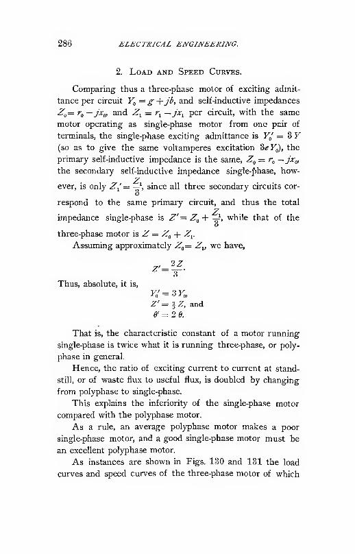
286 ELECTRICAL ENGINEERING.
2. Load and Speed Curves.
Comparing thus a three-phase motor of exciting admit-
tance per circuit I^ =^ +J^> and self-inductive impedances
Z^= r„ —jxg, and Z^ = r^ —j\ per circuit, with the same
motor operating as single-phase motor from one pair of
terminals, the single-phase exciting admittance is F/ = 3 F(so as to give the same voltamperes excitation 3^F„), the
primary self-inductive impedance is the same, ^„ = r^ —jx^^,
the secondary self-inductive impedance single-phase, how-Z
ever, is only Z^= —\ since all three secondary circuits cor-o
respond to the same primary circuit, and thus the total
Zimpedance single-phase is Z'=Zg+ -^, while that of the
three-phase motor is ^ = ^^ -|- Z^.
Assuming approximately Z'„= Z^, we have,
Z'=

INDUCTION MACHINES. 287
the curves of one circuit are given in Figs. 125 and 126, of
the constants
:
Three-phase, Single-phase.
F„ = .oi + .iy,
Zo = .1 — Zj,
Z, = .l-.3j,
Thus, 6 = 6.36.
Fo = .03 + .3J,
Zo = .1 - .3J,
Zi = .033 - .ly,
Thus, e = 12.72.
Fig. 730.

288 ELECTRICAL ENGINEERING.
It is of interest to compare Fig. 130 with Fig. 125 and
to note the lesser drop of speed (due to the relatively lower
secondary resistance) and lower power factor and efficiencies,,
especially at light load. The maximum output is reduced
from 3 X 7000 = 21,000 in the three-phase motor to 9100
watts in the single-phase motor.
Since, however, the internal losses are less in the single-
phase motor, it can be operated at from 25 to 30 ^ higher
magnetic density than the same motor polyphase, and in
this case its output is from | to | that of the polyphase
motor.
The preceding discussion of the single-phase induction
motor is approximate, and correct only at or near synchro-
nism, where the magnetic field is practically a uniformly
rotating field of constant intensity, that is, the quadrature
flux produced by the armature magnetization equal to the
main magnetic flux produced by the impressed E.M.F.
If an accurate calculation of the motor at intermediate
speed and at standstill is required, the change of effective
exciting admittance and of secondary impedance, due to the
decrease of the quadrature flux, have to be considered.
At synchronism the total exciting admittance gives the
M.M.F. of main flux and auxiliary flux, while at standstill
the quadrature flux has disappeared or decreased to that
given by the starting device, and thus the total exciting ad-
mittance has decreased to one-half of its synchronous value,,
or one-half plus the exciting admittance of the starting flux.
The effective secondary impedance at synchronism is the
joint impedance of all secondary circuits, at standstill, how-
ever, only the joint impedance of the projection of the
secondary coils on the direction of the main flux, that is,
twice as large as at synchronism. In other words, from
standstill to synchronism the effective secondary impe-
dance gradually decreases to one-half its standstill value at
synchronism.
For fuller discussion hereof the reader must be referred

INDUCTION MACHINES. 289
to my second paper on the Single-phase Induction Motor,
Transactions A. I. E. E., 1900, page 37.
The torque in Fig. 131 obviously slopes towards zero at
standstill. The effect of resistance inserted in the secondary
of the single-phase motor is similar as in the polyphase motor
in so far as an increase of resistance lowers the speed at
which the maximum torque takes place. While, however,
in the polyphase motor the maximum torque remains the
same, and merely shifts towards lower speed with the increase
of resistance, in the single-phase motor the maximum torque
decreases proportionally to the speed at which the maximumtorque point occurs, due to the factor (1 - s) entering the
equation of the torque,
T^e'a^il-i).
Thus, in Fig. 132 are given the values of torque of the
single-phase motor for the same conditions and the same
motor of which the speed curves polyphase are given in
Fig. 128.

290 ELECTRICAL ENGINEERING
increased by the insertion of secondary resistance, just as in
the polyphase motor.
3. Starting Devices of Single-phase Motors.
At standstill, the single-phase induction motor has no
starting torque, since the line of polarization due to the
armature currents coincides with the axis of magnetic flux
impressed by the primary circuit. Only when revolving,
torque is produced, due to the axis of armature polarization
being shifted by the rotation, against the axis of magnetism,
until at or near synchronism it is in quadrature therewith,
and the magnetic disposition thus identical with that of the
polyphase induction motor.
Leaving out of consideration starting by mechanical
means, and starting by converting the motor into a series or
shunt motor, that is, by passing the alternating current by
means of commutator and brushes through both elements of
the motor, the following methods of starting single-phase
motors are left :
1st. Shifting of the axis of armature or secondary polari-
zation against the axis of inducing magnetism.
2d. Shifting the axis of magnetism, that is, producing a
magnetic flux displaced in position from the flux inducing
the armature currents.
The first method requires a secondary system which is
unsymmetrical in regard to the primary, and thus, since the
secondary is movable, requires means of changing the
secondary circuit, such as commutator brushes short circuit-
ing secondary coils in the position of effective torque, and
open circuiting them in the position of opposing torque.
Thus this method leads to the repulsion motor, which is
a commutator motor also.
With the commutatorless induction motor, or motor with
permanently closed armature circuits, all starting devices
consist in establishing an auxiliary magnetic flux in phase

INDUCTION MACHINES. 291
with the induced secondary currents in time, and in quadra-
ture with the Hne of armature polarization in space. Theyconsist in producing a component of magnetic flux in quad-
rature in space with the primary magnetic flux inducing the
armature currents, and in phase with the latter ; that is, in
quadrature with the primary magnetic flux.
Thus if,
P = polarization due to the induced or armature currents,
M = auxiliary magnetic flux,
</) = phase displacement in time between M and P,and,
0) = phase displacement in space between M zxA P,
the torque is,
T=PM sin (D cos <^.
In general the starting torque, apparent torque efficiency,
etc., of the single-phase induction motor with any of these
devices are given in percent of the corresponding values of
the same motor with polyphase magnetic flux, that is, with a
magnetic system consisting of two equal magnetic fluxes in
quadrature in time and space.
The infinite variety of arrangements proposed for start-
ing single-phase induction motors can be grouped into three
classes.
1. Phase-Splitting Devices. The primary system is
composed of two or more circuits displaced from each other
in position, and combined with impedances of different in-
ductance factors so as to produce a phase displacement
between them.
When using two motor circuits, they can either be con-
nected in series between the single-phase mains, and shunted
with impedances of different inductance factors, as,- for in-
stance, a condensance and an inductance, or they can be
connected in shunt between the single-phase mains but in
series with impedances of different inductance factors. Ob-
viously the impedances used for displacing the phase of the
292 ELECTRICAL ENGINEERING.
exciting coils can either be external or internal, as represented
by high-resistance winding in one coil of the motor, etc.
In this class belongs the use of the transformer as a
phase- splitting device, by inserting a transformer primary in
series to dne motor circuit in the main line, and connecting
the other motor circuit to the secondary of the transformer,
or by feeding one of the motor circuits directly from the
mains, and the Other from the secondary of a transformer
connected across the mains with its primary. In either
case, it is the internal impedance, respectively internal admit-
tance, of the transformer which is combined with one of the
motor circuits for displacing its phase, and thus this arrange-
ment becomes most effective by using transformers of high
internal impedance or admittance, as constant power trans-
formers or open magnetic circuit transformers.
2. Inductive Devices. The motor is excited by the
combination of two or more circuits which are in inductive
relation to each other. This mutual induction between the
motor circuits can either take place outside of the motor in
a separate phase-splitting device, or in the motor proper.
In the first case the simplest form is the divided circuit
whose branches are inductively related to each other by
passing around the same magnetic circuit external to the
motor.
In the second case the simplest form is the combination
of a primary exciting coil and a short circuited secondary coil
induced thereby on the primary member of the motor, or a
secondary coil closed by an impedance.
In this class belong the use of the shading coil and the
accelerating coil.
3. Monocyclic Starting Devices. An essentially watt-
less E.M.F. of displaced phase is produced outside of the
motor, and used to energize a cross magnetic circuit of the
motor, either directly by a special teaser coil on the motor,
or indirectly by combining this wattless E.M.F. with the
main E.M.F.and thereby deriving a system of E.M.F.'s

INDUCTION MACHINES. 293
of approximately three-phase or any other relation. In this
case the primary system of the motor is supplied essentially
by a polyphase system of E.M.F. with a single-phase flow
of energy, a system, which I have called " monocyclic."
For a complete discussion and theoretical investigation
of the different starting devices, the reader must be referred
to the paper on the single-phase induction motor, "Ameri-
can Institute of Electrical Engineers' Transactions, 1898,"
February.
The use of the resistance-inductance, or monocyclic
starting device with three-phase wound induction motor,
will be discussed somewhat more explicitly as the only
method not using condensers, which has found extensive
commercial application. It gives relatively the best starting
torque and torque efficiencies.
In Fig. 133, M represents a three-phase induction motor
of which two terminals, 1 and 2, are connected to single-
I
Fig. 133.
phase mains, and the terminal 3 to the common connection
of a conductance a (that is, a resistance -1 and an equal
susceptance /a [thus a reactance — -j connected in series
across the mains.
Let Y= g + jb = total admittance of motor between
terminals 1 and 2 while at rest. We then have,
4 F = total admittance from terminal 3 to terminals 1
and 2, regardless whether the motor is delta or Y wound.
Let e = E.M.F. in single-phase mains.
E = difference of potential across conductance a of the
starting device.

294 ELECTRICAL ENGINEERING.
We then have,
Current in iz, ^ = Ea,
E.M.F. across /a, e — E.
Thus, current in ja,
h=Ja{e — E),
Thus current in cross magnetizing motor circuit from 3 to
1.2,
/o = /i - /a = E^-ja (e - E).
The E.M.F. of the cross magnetizing circuit is, as may-
be seen from the diagram of E.M.F. 's, which form a tri-
angle with Eg £ and ^ — ^ as sides,
Eo = E - (e -E) = 2E - e,
and since,
we have,
Ea -ja (e- E) = * y(2E - e).
This expression solved for E becomes,
3a + 3ja-8V)
which from the foregoing value of E^ gives,
Ea =3 ea (j — 1)
"° 3a + 3ja-8Y'or, substituting,
expanding, and multiplying both numerator and denomi-
nator by(3a- 8^"-) - /(3a - Si),
'""' ^•=" »-u)- + (--«>)
and the imaginary component thereof, or E.M.F. in quadra-
ture to e in time and in space, is
E^ = — jeaifl-lgj + ifi-lbj

INDUCTION MACHINES. 295
In the same motor on three-phase circuit this quadrature
E.M.F. is the altitude of the equilateral triangle with e as
V3sides, thus =je—^, and since the starting torque of the
motor is proportional to this quadrature E.M.F., the relative
starting torque of the monocyclic starting device, or the
ratio of starting torque of the motor with monocyclic start-
ing device that of the same motor on three-phase circuit, is
EJ ^2 a 2a-^{g-b)
2
For further discussion of this subject the reader is
referred to the paper on " Single-phase Induction Motors "
mentioned above.
4. Acceleration with Starting Device.
The torque of the single-phase induction motor (without
starting device) is proportional to the product of main flux
or magnetic flux produced by the primary impressed E.M.F.,
and the speed. Thus it is the same as in the polyphase
motor at or very near synchronism, but falls off with decreas-
ing speed and becomes zero at standstill.
To produce a starting torque, a device has to be used to
impress an auxiliary magnetic flux upon the motor, in quad-
rature with the main flux in time and in space, and the start-
ing torque is proportional to this auxiliary or quadrature
flux. During acceleration or at intermediate speed, the torque
of the motor is the resultant of the main torque, or torque
produced by the primary main flux, and the auxiliary
torque produced by the auxiliary quadrature or starting flux.
In general, this resultant torque is not the sum of main and
auxiliary torque, but less, due to the interaction between
the motor and the starting device.
All the starting devices depend more or less upon the
total admittance of the motor and its power factor. With

296 ELECTRICAL ENGINEERING.
increasing speed, however, the total admittance of the motor
decreases, and its power factor increases, and an auxiliary-
torque device suited for the admittance of the motor at
standstill will not be • suited for the changed admittance at
speed.
The currents induced in the secondary by the main or
primary magnetic flux are carried by the rotation of the
motor more or less in quadrature position, and thus produce
the quadrature flux giving the main torque as discussed
before.
This quadrature component of the main flux induces an
E.M.F. in the auxiliary circuit of the starting device, and
thus. changes the distribution of currents and E.M.F.'s in
the starting device. The circuits of the starting device
then contain, besides the motor admittance and external
admittance, an active counter E.M.F., changing with the
speed. Inversely, the currents produced by the counter
E.M.F. of the motor in the auxiliary circuit react upon the
counter E.M.F., that is, upon the quadrature component of
main flux, and change it.
Thus during acceleration we have to consider :
1. The effect of the change of total motor admittance,
and its power factor, upon the starting device.
2. The effect of the counter E.M.F. of the motor upon
the starting device, and the effect of the starting device
upon the counter E.M.F. of the motor.
1. The total motor admittance and its power factor
change very much during acceleration in motors with short
circuited low resistance secondary. In such motors the
admittance at rest is very large and its power factor low,
and with increasing speed the admittance decreases and its
power factor increases greatly. In motors with short cir-
cuited high resistance secondary, the admittance also de-
creases greatly during acceleration, but its power factor
changes less, being already high at standstill. Thus the
starting device will be affected less. Such motors, however,

INDUCTION MACHINES. 297
are inefficient at speed. In motors with variable secondary
resistance the admittance and its power factor can be main-
tained constant during acceleration, by decreasing the resist-
ance of the secondary circuit in correspondence with the
increasing counter E.M.F. Hence, in such motors the start-
ing device is not thrown out of adjustment by the changing
admittance during acceleration.
In the phase-splitting devices, and still more in the
inductive devices, the starting torque depends upon the
internal or motor admittance, and is thus essentially affected
by the change of admittance during acceleration, and by the
appearance of a counter E.M.F. during acceleration, which
throws the starting device out of its proper adjustment, so
that frequently while a considerable torque exists at stand-
still, this torque becomes zero and then reverses at some
intermediate speed, and the motor, while starting with fair
torque, is not able to run up to speed with the starting
device in circuit. Especiall)^ is this the case where capacity
is used in the starting device.
IV. Induction Generator.
1. Introduction.
In the range of slip from j = to j = 1, that is, from
synchronism to standstill, torque, power output, and power
input of the induction machine are positive, and the machine
thus acts as a motor, as discussed before.
Substituting, however, in the equations in paragraph 1
for s values > 1, corresponding to backward rotation of the
machine, the power input remains positive, the torque also
remains positive, that is, in the same direction as for J < 1,
but since the speed (1 — s) becomes negative or in opposite
direction, the power output is negative, that is, the torque
in opposite direction to the speed. In this case, the machine
consumes electrical energy in its primary and mechanical
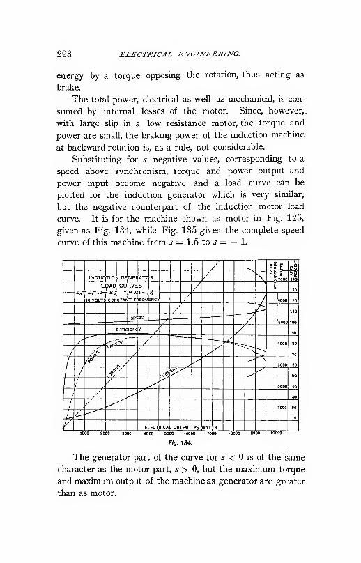
298 ELECTRICAL ENGINEERING.
energy by a torque opposing the rotation, thus acting as
brake.
The total power, electrical as well as mechanical, is con-
sumed by internal losses of the motor. Since, however,,
with large slip in a low resistance motor, the torque and
power are small, the braking power of the induction machine
at backward rotation is, as a rule, not considerable.
Substituting for s negative values, corresponding to a
speed above synchronism, torque and power output and
power input become negative, and a load curve can be
plotted for the induction generator which is very similar,
but the negative counterpart of the induction motor load
curve. It is for the machine shown as motor in Fig. 125,
given as Fig. 134, while Fig. 135 gives the complete speed
curve of this machine from .? = 1.5 to j = — 1.

INDUCTION MACHINES. 299
Thus an induction motor when speeded up above syn-
chronism acts as powerful brake by xeturning energy into
the Unes, and the maximum braking effect or the maximumenergy returned by the machine will be greater than the
maximum motor torque or output.

300 ELECTRICAL ENGINEERING.
devices, running up beyond synchronous speed as much as
required to consume the power suppHed to it.
Conversely, however, if an induction machine is driven at
constant speed and connected to a suitable circuit as load,
the frequency given by the machine will not be synchronous
with the speed or constant at all loads, but decreases with
increasing load from practical synchronism at no load, and
thus for the induction generator at constant speed a load
curve can be constructed as shown in Fig. 136, giving the

INDUCTION MACHINES. 301
3. Power Factor of Induction Generator.
The induction generator differs essentially from a syn-
chronous alternator (that is, a machine in which an armature
revolves relatively through a constant or continuous mag-netic field) by having a power factor requiring leading cur-
rent. That is, in the synchronous alternator the phase
relation between current and terminal voltage depends en-
tirely upon the external circuit, and according to the nature
of the circuit connected to the synchronous alternator the
current can lag or lead the terminal voltage or be in phase
therewith. In the induction or asynchronous generator,
however, the current must lead the terminal voltage by the
angle corresponding to the load and voltage of the machine,
or in other words the phase relation between current and
voltage in the external circuit must be such as required by
the induction generator at that particular load.
Induction generators can operate only on circuits with
leading current or circuits of negative effective reactance.
In Fig. 137 are given for the constant speed induction
generator in Fig. 136 as function of the impedance of the

302 ELECTRICAL ENGINEERING.
external circuit £ = -r^ as abscissae (where e^ = terminal volt-
age, Zj = current in external circuit), the leading power factor
/ = cos o) required in the load, the inductance factor q =sin (1), and the frequency.
Hence, when connected to a circuit of impedance s this
induction generator can operate only if the power factor of
its circuit is p ; and if this is the case the voltage is indefinite,
that is, the circuit unstable, even neglecting the impossibility
of securing exact equality of the power factor of the external
circuit with that of the induction generator.
Two possibilities thus exist with such an induction
generator circuit.
1st. The power factor of the external circuit is constant
and independent of the voltage, as when the external circuit
consists of resistances, inductances, and capacities.
In this case if the power factor of the external circuit is
higher than that of the induction generator, that is, the lead-
ing current less, the induction generator fails to excite and
generate. If the power factor of the external circuit is
lower than that of the induction generator, the latter excites
and its voltage rises until by saturation of its magnetic cir-
cuit and the consequent increase of exciting admittance,
that is, decrease of internal power factor, its power factor has
fallen to equality with that of the external circuit.
In this respect the induction generator acts like the
direct current shunt generator, that is, it becomes stable
only at saturation, but loses its excitation and thus drops
its load as soon as the voltage falls below saturation.
Since, however, the field of the induction generator is
alternating, it is usually not feasible to run at saturation,
due to excessive hysteresis losses, except for very low fre-
quencies.
2d. The power factor of the external circuit depends
upon the voltage impressed upon it.
This, for instance, is the case if the circuit consists of a

INDUCTION MACHINES. 303
synchronous motor or contains synchronous motors or syn-
chronous converters.
In the synchronous motor the current is in phase with
the impressed E.M.F. if the impressed E.M.F. equals the
counter E.M.F. of the motor, plus the internal loss of volt-
age. It is leading if the impressed E.M.F. is less, and
lagging if the impressed E.M.F. is more. Thus when con-
necting an induction generator with a synchronous motor, at
constant field excitation of the latter the voltage of the in-
duction generator rises until it is as much below the counter
E.M.F. of the synchronous motor as required to give the
leading current corresponding to the power factor of the
generator. Thus a system consisting of a constant speed
induction generator and a synchronous motor at constant
field excitation is absolutely stable. At constant field exci-
tation of the synchronous motor, at no-load the synchronous
motor runs practically at synchronism with the induction
generator, with a terminal voltage slightly below the coun-
ter E.M.F. of the synchronous motor. With increase of
load the frequency and thus the speed of the synchronous
motor drops, due to the slip of frequency in the induction
generator, and the voltage drops, due to the increase of lead-
ing current required, and the decrease of counter E.M.F.
caused by the decrease of frequency.
By increasing the field excitation of the synchronous
motor with increase of load, obviously the voltage can be
maintained constant, or even increased with the load.
When running from an induction generator a synchro-
nous motor gives a load curve very similar to the load curve
of an induction motor running from a synchronous generator;
that is, a magnetizing current at no-load and a speed gradu-
ally decreasing with the increase of load up to a maximumoutput point, at which the speed curve bends sharply down,
the current curve upward, and the motor drops out of step.
The current, however, in the case of the synchronous
motor operated from an induction generator is leading, while

804 ELECTRICAL ENGINEERING.
it is lagging in an induction motor operated from a synchro-
nous generator.

INDUCTION MACHINES. 305
generator, the over-compounding being such as to give
approximately constant terminal voltage, e.
Obviously when operating a self-exciting synchronous
converter from an induction generator, the system is unstable
also, if both machines are below magnetic saturation, since
in this case in both machines the induced E.M.F. is propor-

306 ELECTRICAL ENGINEERING.
a synchronous machine as exciter in the circuit supplying the
required leading current to the induction generator ; and in
this case the voltage of the system is controlled by the field
excitation of the synchronous machine, that is, its counter
E.M.F. Either a synchronous motor of suitable size running
light can be used herefor as exciter of the induction gen-
erator, or the leading exciting current of the induction
generator may be derived from synchronous motors or con-
verters in the same system, or from synchronous alternating
current generators operated in parallel with the induction
generator, in which latter case, however, these currents come
from the synchronous alternator as lagging currents. Elec-
trostatic condensers may also be used for excitation, but in
this case besides the condensers a synchronous machine is
required to secure stability.
Therefore, induction generators are more suited for cir-
cuits- which normally carry leading currents, as synchronous
motor and synchronous converter circuits, but less suitable
for circuits with lagging currents, since in the latter case
an additional synchronous machine is required, giving all the
lagging currents of the system plus the induction generator
exciting current.
Obviously, when running induction generators in parallel
with a synchronous alternator, no synchronizing is required,
but the induction generator takes a load corresponding to
the excess of its speed over synchronism, or conversely if the
driving power behind the induction generator is limited, no
speed regulation is required, but the induction generator runs
at a speed exceeding synchronism by the amount required
to consume the driving power.
The foregoing consideration obviously applies to the
polyphase induction generator as well as the single-phase
induction generator, the latter, however, requiring a larger
exciter in consequence of its lower power factor. Thecurves shown in the preceding apply to the machine as
polyphase generator.

INDUCTION MACHINES. 307
The effect of resistance in the secondary is essentially
the same in the induction generator as in the induction motor.
An increase of resistance increases the slip, that is, requires
an increase of speed at the same torque, current and output,
and thus correspondingly lowers the efficiency.
Regarding the synchronous induction machine, that is,
a machine having a single-phase or polyphase primary and a
single-phase secondary, I must refer to my book, " Theory
and Calculation of Alternating Current Phenomena," where
it is shown that such a machine not only operates like an
ordinary induction machine as motor below and as generator
above synchronism, 'but can operate also at synchronism
either as generator or as motor, according to the phase
relation between the impressed E.M.F. and the position of
the secondary circuit, the work being done in a similar
manner as in a reaction machine by a distortion of the wave
shape, or what may be called an energy component of self-
induction, due to a periodic variation of inductance.
V. Induction Booster.
In the induction machine, at a given slip s, current and
terminal voltage are proportional to each other and of con-
stant phase relation, and their ratio is a constant. Thus
when connected in an alternating circuit, whether in shunt
or in series, and held at a speed giving a constant and definite
slip s, either positive or negative, the induction machine acts
like a constant impedance.
The apparent impedance and its components, the apparent
tresistance and apparent reactance represented by the induc-
tion machine, vary with the slip. At synchronism apparent
impedance, resistance, and reactance are a maximum. They
decrease with increasing positive slip. With increasing
negative slip the apparent impedance and reactance decrease
also, the apparent resistance decreases to zero and then in-
creases again in negative direction as shown in Fig. 140,

308 ELECTRICAL ENUlNEERINL
which gives the apparent impedance, resistance, and reactance
of the machine sliown in Figs. 125 and 126, etc., with the
speed as abscissae.

INDUCTION MACHINES. 309
inserted in series in an alternating current circuit can be
used as a booster ; that is, as an apparatus to produce and
insert in the circuit an E.M.F. proportional to the current,
and the amount of the boosting effect can be varied by
varying the speed, that is, the slip at which the induction
machine is revolving. Above synchronism the induction
machine boosts ; that is, raises the voltage ; below synchron-
ism it lowers the voltage ; in either case also adding an out-
of-phase E.M.F. due to its reactance. The greater the slip,
either positive or negative, the less is the apparent resist-
ance, positive or negative, of the induction machine.
The effect of resistance inserted in the secondary of the
induction booster is similar to that in the other applications
of the induction machine ; that is, it increases the slip
required for a certain value of apparent resistance, thereby
lowering the efficiency of the apparatus, but at the same
time making it less dependent upon minor variations of speed
;
that is, requires a lesser constancy of slip, and thus of speed
and frequency, to give a steady boosting effect. .
VI. Phase Converter.
It may be seen from the preceding, that the induction
machine can operate equally well as motor, below synchron-
ism, and as generator, above synchronism.
In the single-phase induction machine, the motor or
generator action occurs in one primary circuit only, but in
the direction in quadrature to the primary circuit a mere
magnetizing current flows, either in the armature, in the
single-phase motor proper, or in an auxiliary field-circuit, in
the monocylic motor.
The motor and generator action can occur, however,
simultaneously in the same machine, some of the primary
circuits acting as motor, others as generator circuits. Thus,
if one of the two circuits of a quarter-phase induction machine
is connected to a single-phase system, in the second circuit

310 ELECTRICAL ENGINEERING.
an E.M.F. is induced in quadrature with and equal to the
induced E.M.F. in the first circuit ; and this E.M.F. can thus
be utilized to generate currents which, with currents taken
from the primary single-phase mains, give a quarter-phase
system. Or, in a three-phase motor connected with two
of its terminals to a single-phase system, from the third
terminal, an E.M.F. can be derived which, with the single-
phase system feeding the induction machine, combines to a
three-phase system. The induction machine in this applica-
tion represents a phase converter.
The phase converter obviously combines the features of a
single-phase induction motor with those of a double trans-
former, transformation occurring from the primary or motor
circuit to the secondary or armature, and from the secondary
to the tertiary or generator circuit.
Thus, in a quarter-phase motor connected to single-phase
mains with one of its circuits.
If,
Y^= g -\- jb = primary polyphase exciting admittance,
^0= ^o~y-*^o= self-inductive impedance per primary or ter-
tiary circuit,
Zj= ri — jx-^ = resultant single-phase self-inductive impe-
dance of secondary circuits.
Let
e = E.M.F. induced by mutual flux, and
Z = r — jx = impedance of external circuit supplied bythe phase converter as generator of second phase.
We then have,
I = „ „ = current of second phase generated by phase
converter,
eZE = IZ = y j_ y = 7 = terminal voltage at genera-
^ ztor circuit of phase converter.

INDUCTION MACHINES. 311
The current in the secondary of the phase converter is
then,
/i = /+ /'+/",where
T — load current = Z+Z,2'= I?K = exciting current of quadrature magnetic flux,
I' = — = current required to revolve the machine,
and the primary current is,
!, = !, + 1',
where/'= eYf,= exciting current of main magnetic flux.
From these currents the E.M.F.'s are derived in a similar
manner as in the induction motor or generator.
Due to the internal losses in the phase converter, the
E.M.F. of the two circuits, the motor and generator circuits,
are practically in quadrature with each other and equal only
at no load, but shift out of phase and become more unequal
with increase of load, the unbalancing depending upon the
constants of the phase converter.
It is obvious that the induction machine is used as phase
converter only to change single-phase to polyphase, since a
change from one polyphase system to another polyphase
system can be effected by stationary transformers. Achange from single-phase to polyphase, however, requires a
storage of energy, since the power arrives as single-phase
pulsating, and leaves as steady polyphase flow, and the
momentum of the revolving phase converter secondary
stores and returns the energy.
With increasing load on the generator circuit of the phase
converter its slip increases, but less than with the same load
as mechanical output from the machine as induction motor.
An application of the phase converter is made in single-
phase motors by closing the tertiary or generator circuit by
a condenser of suitable capacity, thereby generating the ex-
citing current of the motor in the tertiary circuit.

312 ELECTRICAL ENGINEERING.
The primary circuit is thereby relieved of the exciting
current of the motor, the efficiency essentially increased, and
the power factor of the single-phase motor with condenser in
tertiary circuit becomes practically unity over the whole
range of load. At the same time, since the condenser cur-
rent is derived by double transformation in the multitooth
structure of the induction machine, which has a practically
uniform magnetic field, irrespective of the shape of the pri-
mary impressed E.M.F. wave, the application of the condenser
becomes feasible irrespective of the wave shape of the gen-
erator.
Usually the tertiary circuit in this case is arranged on an
angle of 60° with the primary circuit, and in starting a power-
ful torque thereby developed, with a torque efficiency supe-
rior to any other single phase motor starting device, and
when combined with inductive reactance in a second ter-
tiary circuit, the apparent starting torque efficiency can be
made even to exceed that of the polyphase induction motor.
Further discussion hereof, see A. I. E. E. Transactions,
1900, p. 37.
Vn. Frequency Converter or General Alternating Current
Transformer.
The E.M.F. 's induced in the secondary of the induction
machine are of the frequency of slip, that is, synchronism
minus speed, thus of lower frequency than the impressed
E.M.F. in the range from standstill to double synchronism;
of higher frequency outside of this range.
Thus, by opening the secondary circuits of the induction
machine, and connecting them to an external or consumer's
circuit, the induction machine can be used to transform from
one frequency to another, as frequency converter.
It lowers the frequency with the secondary running at a
speed between standstill and double synchronism, and raises
the frequency with the secondary either driven backward or
above double synchronism.

INBUCTION MACHINES. 313
Obviously, the frequency converter can at the same timechange the E.M.F., by using a suitable number of primaryand secondary turns, and can change the phases of the systemby having a secondary wound for a different number of
phases than the primary, as, for instance, convert from three-
phase 6000-volts 25-cycle, to quarter-phase 2500-volts 62.5-
cycles.
Thus, a frequency converter can be called a " General
Alterating Current Transformer."
For its theoretical discussion and calculation, see " Theoryand Calculation of Alternate Current Phenomena."
The action and the equations of the general alternating
current transformer or frequency converter are essentially
those of the stationary alternating current transformer, ex-
cept that the ratio of secondary to primary induced E.M.F.
is not the ratio of turns, but the ratio of the product of
turns and frequency, while the ratio of secondary current
and primary load current (that is, total primary current
minus primary exciting current) is the inverse ratio of
turns.
The ratio of the products of induced E.M.F. and current,
that is, the ratio of electric power generated in the secondary,
to electric power consumed in the primary (less excitation),
is thus not unity, but is the ratio of secondary to primary
frequency.
Hence, when lowering the frequency with the secondary
revolving at a speed between standstill and synchronism,
the secondary output is less than the primary input, and the
difference is transformed in mechanical work ; that is, the
machine acts at the same time as induction motor, and when
used in this manner is usually connected to a synchronous
or induction generator feeding preferably into the secondary
circuit (to avoid double transformation of its output) which
transforms the mechanical power of the frequency converter
into electrical power.
When raising the frequency by backward rotation, the

314 ELECTRICAL ENGINEERING.
secondary output is greater than the primary input (or rather
the electric power generated in the secondary greater than
the primary power consumed by the induced E.M.F.) and the
difference is to be supplied by mechanical power by driving
the frequency changer backward by synchronous or induc-
tion motor, preferably connected to the primary circuit, or
by any other motor device.
Above synchronism the ratio of secondary output to
primary input becomes negative ; that is, the induction
machine generates power in the primary as well as the sec-
ondary, the primary power at the impressed frequency, the
secondary power at the frequency of slip, and thus requires
mechanical driving power.
The secondary power and frequency are less than the
primary below double synchronism, more above double syn-
chronism.
As far as its transformer action is concerned, the fre-
quency converter is an open magnetic circuit transformer
;
that is, a transformer of relatively high magnetizing current.
It combines therewith, however, the action of an induction
motor or generator. Excluding the case of over-synchro-
nous rotation, as of lesser importance, it is approximately
(that is, neglecting internal losses) electrical input -^ elec-
trical output -5- mechanical output = primary frequency -^
secondary frequency -=- speed or primary minus secondary
frequency.
That is, the mechanical output is negative when increas-
ing the frequency by backward rotation.
Such frequency converters are to a certain extent in
commercial use, and have the advantage over the motor-
generator plant by requiring an amount of apparatus equal
only to the output, while the motor-generator set requires
machinery equal to twice the output.
An application of the frequency converter when lower-
ing the frequency is made in concatenation or tandem control
of induction machines, as described in the next section. In

INDUCTION MACHINES. 315
this case, the first motor (or all the motors except the last of
the series) are in reality frequency converters.
VIII. Concatenation of Induction Motors.
In the secondary of the induction motor an F.M.F. is
induced of the frequency of slip. Thus connecting the
secondary circuit of the induction motor to the primary of a
second induction motor, the latter is fed by a frequency
equal to the slip of the first motor, and reaches its synchro-
nism at the frequency of slip of the first motor, the first
motor then acting as frequency converter for the second
motor.
If, then, the two induction motors are rigidly connected
together and thus caused to revolve at the same speed, the
speed of the second motor, which' is the slip s of the first
motor at no load, equals the speed of the first motor
s = \ — s, and thus s = .5. That is, a pair of induction
motors connected this way in tandem or in concatenation,
that is, "chain connection," as commonly called, tends to
approach ^ = .5, or half synchronism at no load, slipping
below this speed under load. That is, concatenation of two
motors reduces their synchronous speed to one-half, and thus
offers a means to operate induction motors at one-half speed.
In general, if a number of induction machines are con-
nected in tandem ; that is, the secondary of each motor
feeding the primary of the next motor, the secondary of the
last motor being short circuited, the sum of the speeds of all
motors tends towards synchronism, and with all motors con-
nected together so as to revolve at the same speed, the
system operates at - synchronous speed, when ;z = numbern
of motors.
Assuming the ratio of turns of primary and secondary as
1 : 1, with two induction motors in concatenation at standstill,
the frequency and the E.M.F. impressed upon the necond
motor, neglecting the drop of E.M.F. in the internal impe-

316 ELECTRICAL ENGINEERING.
dance of the first motor, equal that of the first motor. With
increasing speed, the frequency and the E.M.F. impressed
upon the second motor decrease proportionally to each
other, and thus the magnetic flux and the magnetic density
in the second motor, and its exciting current, remain constant
and equal to that of the first motor, neglecting internal losses.
That is, when connected in concatenation the magnetic den-
sity, current input, etc., and thus the torque developed by the
second motor, are approximately equal to that of the first
motor, being less only due to the internal losses in the first
motor.
Hence, the motors in concatenation share the work in
approximately equal portions, and the second motor utilizes
the power which without the use of a second motor at less
than one-half synchronous speed would have to be wasted
in the secondary resistance. That is, theoretically concate-
nation doubles the torque and output for a given current, or
power input into the motor system. In reality the gain is
somewhat less, due to the second motor not being quite
equal to a non-inductive resistance for the secondary of the
first motor, and due to the drop of voltage in the internal
impedance of the first motor, etc.
At one-half synchronism, that is, the limiting speed of the
concatenated couple, the current input in the first motor
equals its exciting current plus the transformed exciting cur-
rent of the second motor, that is, equals twice the exciting,
current.
Hence, comparing the concatenated couple with a single
motor, the primary exciting admittance is doubled. Thetotal impedance, primary plus secondary, is that of both
motors, that is doubled also, and the characteristic constant
of the concatenated couple is thus four times that of a single
motor, but the speed reduced to one-half.
Comparing the concatenated couple with a single motor
rewound for twice the number of poles, that is, one-half speed
also, such rewinding does not change the impedance, but

INDUCTION MACHINES. 317
quadruples the admittance, since one-half as many turns per
pole have to produce the same flux in one-half the pole arc,

318 ELECTRICAL ENGINEERING.
The slip under load, however, is less in the concatenated
couple than in the motor with twice the number of poles,
being due to only one-quarter the internal impedance, the
secondary impedance of the second motor only, and thus
the efficiency is higher.
Two motors coupled in concatenation are in the range
from standstill to one-half synchronism, approximately equiv-
alent to one motor of twice the admittance, three times the
8000 Is

INDUCTION MA CHINES. 319
cuits. Herefor the reader must be referred to " Theory and
Calculation of Alternate Current Phenomena," 3d edition.
The load curves of the pair of three-phase motors of the
same constants as the motor in Figs. 125 and 126 are given
in Fig. Irtl, the complete speed curve in Fig. 142.
Fig. 141 shows the load curve of the total couple, of the
two individual motors, and of the equivalent motor.
As seen from the speed curve, the torque from stand-
still to one-half synchronism has the same shape as the
torque curve of a single motor between standstill and syn-
chronism. At one-half synchronism the torque reverses and

320 ELECTRICAL ENGINEERING.
without changing its value. Beyond half-synchronism, how-
ever, resistance in the secondary lengthens the generator
part of the curve, and makes the second motor part of the
curve more or less disappear, as seen in Fig. 143, which
gives the speed curves of the same motor as Fig. 142, with
resistance in circuit in the secondary of the second motor.
The main advantages of concatenation are obviously the
ability of operating at two different speeds, the increased
torque and power efficiency below half-speed, and the gene-
rator or braking action between half-speed and synchronism.

INDEX.
PAGEAcceleration with starting device, sin-
gle-phase induction motor . . . 295
Admittance . . ... . )05
absolute, of induction motor . . . 275
primary, of transformer 85
and impedance . . 103
Algebraic calculation of transformer . . 75
Alternating current circuits, self-induc-
tion 29
, currents, effect . .... . ,38
current generator, characteristic
curves ... 139
current induction, formula .... 16
current transformer 69
E.M.F 13
wave 30
Alternators ... , • • 123
Ampere ... 2
Ampere-turn . . . . ... 2
Ampere-turns per cm . 3
Angle of hysteretic lead ... . , 50
of lag 34
Armature current and heating of con-
verters 228
reaction, commutating machines . . 187
reaction of converters .... 236
reaction of synchronous machines . 129
resistance in polyphase induction
motor 277
winding 165
Apparent efficiency . 270
power efficiency . . . . 270
reactance 52
torque efficiency .... . 270
Arc lamp . . 125
light machines . . _. . 124
Asynchronous, see induction.
Auto-transformer . ... . 125
See compensator.
Auxiliary magnetic flux, single-phase in-
duction motor . 291
Average induced E.M.F. 12
Backward rotation of induction machine
,
297
Balancmg effect of polyphase synchro.
nous motors . 152
Battery, primary and secondary
Biphase, see quarter-phase.
Bipolar machines, commutating
Booster . ...induction
Brushes, angle of lead .
Brush arc machine ,
PACE125
. . 163
123, 125
307
181
. . 124
Calculation of polyphase induction mo-
tor .. . . 2G6
Capacity and condensers . . 55
reactance .... 57
of transmission line . ... 57
in induction motor secondary . . 57
Characteristic constant of induction mo-tor 276
constant of single-phase induction
motor .... . . 286
curves of alternating current genera-
tor . .139curves of commutating machines . 192
curves of synchronous motors . 143
magnetic .... ,8Charge of condenser . . . 55
Charging current of condenser . . 56current of transmission line . . 57
Choking coil . .... 125
Circle representing sine wave in polar
coordinates . . .41Classification of electrical apparatus . . 121
Closed circuit winding ... . 168
Coefficient of hysteresis 52
Commutating machines .... 122, 162
machines, synchronous .... 124
Commutation . . ... , . 193
of converter ... ... 242
of direct current converter .... 259
Compass needle ... &Compensator . . 125
with direct current converter . . . 252
synchronous . 123
Complex imaginary quantity, introduc-
tion •. 80
Components, energy and wattless . . 40
Compounding commutating machines . 190
of converter 242
321

322 INDEX.
33
122, ]24
123, 251
J24, 312
304
Compounding curve ol commutating ma-
chine 191
curves of synchronous generator . . 139
curves ol synchronous motor . 144
ot transmission line for constant vol-
tage . .... 95
Compound generator, commutatmg 211
machines, commutating 163
motor, commutating .... 215
Concatenation of induction motors . 315
Condenser 125
and capacity . 55
charging current 56
Conductance . .^ 105
Conductivity, magnetic . . .4Constant current load saturation curve . 189
resistance load saturation curve . 190
speed induction generator . . . 299
Continuous current, etc., see direct cur-
rent, etc.
Continuous E.MF.Converter . . ...
direct current . . .
frequency
and induction generator
and motor generator . . ... 217
phase 1^phase induction . .
synchronous ... ... 217
as synchronous motor, etc 250
Coordinates, polar 41
rectangular . . , . 79
Counter E.M.F. of impedance .... 42
of resistance . . 32. 42
of self-induction .... 31, 42
Cross-currents in parallel operation of
alternators
.
° . . 155, 157
Cross-magnetization, single-phase induc-
tion motor . 283
Cumulative compounding .... 163, 215
Current, electric . 2,9
starting of 22
stopping of . . . . 24
Cylinder winding, see drum winding . . 164
DemagBetization curve, commutating
machine . . 205
of field pole, commutating machine . 179
Demagnetizing and magnetizing arma-
ture reaction of converter . 240
armature reaction, synchronous ma-
chines 130
Diamagnetic material . . ... 4
Dieleqtrichysteresiscurrent of condenser, 57
Differential compounding .... 163,215
Diphase, see quarter-phase.
Direct current converter 123, 251
PAGEDirect current induction, formula ... 13
self-induction ... ... 22
starting of 22
stopping of, 24
Distorting armature reaction of con
verter . 240
of synchronous machines ... 130
Distortion of field, commutating ma-
chine 179
Distribution ofmagnetic flux, commutat-
ing machines 177
Division of load in parallel operation of
alternators 156
Double current generators .... 124, 248
Double reentrant armature winding . . 169
Double spiral armature winding . . . 169
Drum winding 164
Dynamotors ]23
Eddy currents, effective resistance . . 53
in pole face 185
Effect and effective values 15
of armature resistance and starting,
polyphase induction motor . . . 277
of alternating currents 38
of saturation on magnetic distribu-
tion 181.
of slots on magnetic flux .... 184
transmission line 41
Effective alternating wave 16
impedance . , 53
reactance • '. 52, 104
resistance 52, 104
resistance and hysteresis .... 48
values and efiFect 15
Efficiency . . . 270
and losses, commutating machines . 193
and losses in synchronous machines , 150
curves of synchronous machines . 151
of induction motor .... 272
Electric current 9
Electrolytic apparatus . . 122
cell .... 125
Electromotive force, see E.M.F.Electrostatic apparatus .... 122
E.M.F 9
and magnetism ... .... 9
average induced ... ... 12
induction of 11
instantaneous induced . . < .12maximum induced ... .12of self-induction . . . . . 9
Energy cross-currents of alternators . . 156
current . ... 40
E.M.F ... ... ,39Engine regulation with alternators . . 158
Equalizers with compounded alternators . 161

INDEX. 323
PAGEEquivalent induction motor, concatena-
tion 317
sine waves 112
Excitation, field II
single-phase induction motor . . 283
Exciter of induction generator . . , 306
Exciting current of magnetic circuit . 49, 50
current, primary, of transformer . 71
current, single-phase induction mo-tor 282
External characteristic, series generator . 208
characteristic, shunt generator . . 206
Face commutator machines . . 164
Farad 55
Field characteristic, commutating ma-
chine 192
characteiij.ic cf synchronous gen-
erator 140
excitation .... 11
intensity, magnetic 1
Fluctuating cross-currents in parallel op-
eration of alternators 157
Flux, magnetic ... . ... 1
Form factor of alternating wave ... 16
Form factor in synchronous machines . 126
Formula of alternating current induc-
tion 16
of direct current induction . . 13
induction, of synchronous machines, 126
Foucault currents, effective resistance . 63
Four-phase, see quarter-phase.
Fractional pitch armature winding . 173
Frequency of commutation . . 195
converters . . . 124
Frequency converter or general alternat-
ing current transformers . . . 312
Friction, molecular magnetic . 49
Full pitch armature winding 173
Furnace, electric .... . . 125
Generator action of concatenated couple, 319
action of frequency converter . . . 314
Gerferators, alternating 123
alternating current , characteristic
curves 139
commutating 123
double current 124,248
induction 124 297
Gramme winding, see ring winding 164
Heater, electric 125
Heating and armature currents of con-
verter 228
of direct current converters . . . 259
Henry 20
Hexaphase, see six-phase.
PAGEHorizontal component of sine wave . . 80
intensity of terrestrial magnetic
field 14
Hunting of synchronous machine . . 158
Hysteresis coefficient ... 52
current .50dielectric 57
and effective resistance . . 48
loss 52
magnetic .... .... 49
Hysteretic effective resistance . . 52
lead angle 50
Imaginary quantity, introduction . 80
Impedance . . .34, 104
absolute, of induction motor . 275
and admittance . lOS
counter E.M.F of . . . 42
effective . , 53
effective, of induction machine , 308
E.M.F. consumed by . . 42
of transmission lines ... 58
Incandescent lamp .... 125
Induced E.M.F., average . . 12
commutating machines . . , 175
instantaneous ... . . 12
maximum .12of synchronous machines . . 128
Inductance . . 18
factor, induction generator . . 301
unit of 20
Induction, alternating current, formula . 16
apparatus, stationary .... 122, 125
booster 307
converters, see reaction converters,
direct current, formula . 13
of E.M.F. 's ... . . 11
formula of synchronous machines . 126
generator . . . 297
generator and converter , , . 303
generator, constant speed , . . 299
generator, magnetic saturation 302
generator, power factor . . . . 301
generator and synchronous machine, 303
machine.s 122, 124. 261
magnetic 4
motor 65. 124
motors, concatenation of .... 315
motor, single-phase, starting ... 108
mutual and self 18
phase converter 300
Inductive devices, starting single-phase
induction motor 292
Inferiority of single-phase induction mo-tor 286
Instantaneous induced E.M.F. . . 12
Intensit;' of alternating wave .... 43
324 INDEX.
PACKIntensity, magnetic 2
Jnterlinkages, magnetic IS
Inverted converters ... . . 124,246
Iron-clad armatures ... , . , 163
J., y, introduction of ....,., 80
Lag angle 34
Lagging current in converter . . . 242
Lamp, incandescent and arc . . . . 125
Lap winding of armature .... 170
Lead angle of brushes .... . J81
hysteretic 50
Leading current in converter . . Ii42
Lentz's law 10
Lines of magnetic force ... 1
Load, affecting converter ratio . . 226
curves, induction generators, con-
stant frequency 298
characteristic, series generator . . 209
characteristic, series motor .... 214
characteristic; shunt generator . . 206
characteristic, shunt motor . . . 212
characteristics of synchronous motor, 145
characteristic of transmission line . 89
current, primary, of transformer . 71
curves, induction generator, con-
stant speed 300
curves, induction motor concatena-
tion 319
curves of synchronous generator . . 141
magnetic effect on field .... 183
saturation curve, commutating ma-
chine : . . . , 189
saturation curve of commutating ma-
chine 203
saturation curve of synchronous ma-
chine .... 148
and speed curves, polyphase induc-
tion motor 272
and speed curves of single-phase in-
duction motor , c .... 286
Loss curves of synchronous machines 151
Losses and efficiency, commutating ma-
chines . . . . '. . 193
ard efficiency of syricHroHous ma-
chines 150
Loss of energy in pole face 186
Magnet field, inductance 21
Magnetic characteristic or saturation
curve of synchronous machine . 147
distribution, affected by saturation . 181
energy current 50
field 1
field of force". . 1
flux . . 1
PAGE184
291
177
185
49
49
4
18
4
9
1
9
Magnetic flux, affected by slots . . .
flux, auxiliary quadrature, single
phase induction motor . . .
flux distribution, commutating machines
flux, pulsation in pole face . . .
friction
hysteresis
induction
interlinkages . .
material
reaction ....Magnetism and electric currents
and E.M.FMagnetization curves 8
of field pole commutating machines . 179
Magnetizing armature reaction, synchro-
nous machines 130
current 50
and demagnetizing armature reaction
of converter . ,
force
Magneto machines, commutating
Magnetomotive force . .
Magneto and separately excited gener-
ator, commutating
Magnet pole
Maximum induced E.M.F.
mf =r microfarad ....mh =: milhenry . . .
Microfarad .
Milhenry
M.M.F., see magnetomotive force,
Molecular magnetic friction . . ,
Monocyclic devices, starting single-
induction motor
induction motor . .
Mono-phase, see single-phase.
Motor action of frequency converter
Motors, commutating 123
Motor generator and converter . ... 217
Motor, induction 124
synchronous 123, 141
synchronous, characteristic curves * 143
Multiple armature winding . . 164, 165
165
169
165
169
163
18
18
phase
240
3
162
2
205
1
12
55
21
55
21
49
292
264
314
drum winding ....reentrant armature vnnding
ring winding
spiral armature winding . ,
Multipolar machines, commutating
Mutual inductance
Mutual induction and self-induction
Negative resistance of induction ma-
chine .1,
Neutral conductor of three-wire system,
and converter . , c . . .

INDEX. 325
PAGE"Neutral point, line or zone, commutating
machines 178
Nomenclature of electrical apparatus . . 121
Nominal induced E.M.F. of synchronous
machine 128
Nonpolar induction 11
machine 125
"N-phase converter . . 226, 233, 235, 236
direct current converter . . . 252, 259
Ohm 9
Ohms law 103
Open circuit winding 168
coil arc machines 124
Oscillating armature reaction of con-
verter , ; 240
Over-compounding of coQverter . . . 244
curve of commutating machine . . 192
of transmission lines 98
Over-synchronous rotation of induction
machine .... . . . 298
Parallel connection 107
Parallelogram of sine waves 44
Parallel operation of alternators . . . 154
operation of alternators, division of
load 156
operation of alternators, fluctuating
cross-currents .... . . 157
Permeability . . ... . . 4
Phase .... . 13
of alternating wave . . 43
angles G5
characteristics of synchronous motor, J46
control of transmission lines . 94
converters 12 J, 124
converter, induction ... . 309
displacement, affecting converter
ratio 226
displacement in converter, affecting
rating 235
displacement in inverted converter . 247
splitting devices, starting single-
phase induction motor 291
Polar coordinates .41Polarization cell ... . . 125
Pole face, eddy currents .... . 185
energy loss ... 186
pulsation of flux . ... 185
Pole, magnetic .... . . . 1
Polygon of sine waves . . . . 44
Polyphase induction machines . . 124
induction motor 264
induction motor on single-phase cir-
cuit 285
synchronous machines, unbalancing 151
Potential regulator ... .... 125,
PAGEPower efficiency 270
factor of admittance and of impe-
dance, induction motor . . . 275
factor of induction generator . . 301
factor of reactive coil 53
Primary admittance of transformer . 85
Pulsating armature reaction of converter 240
Pulsation of magnetism in pole face . . 185
Quarter-phaser, armature reaction . . 132
Quarter-phase converter, ratio 221, 226, 233,
235,236
direct current converter . . 252, 259
Quadrature magnetic flux, single-phase
induction motor .... . 291
Racing of inverted converter . . . 247
Rating of converter, based on armature
heating 228
of direct current converters . . . 259
of synchronous machines by arma-
ture heating 236
Ratio of E.M.Fs. and of currents in
converters ... . . 218
Reactance . ... 31
capacity . . 57
effective 304
effective or apparent . 52
self-inductive . ... . . 52
synchronous . . 129, 136
of transmission line ... .34Reaction, armature, commutating ma-
chines 187
armature, of converters . ... 236
armature, of synchronous machines 129
converters ... . . 243
magnetic .... . ... 9
Reactive coil 53, 125
Real induced E. M. F. of synchronous
machine . . . , . ... 128
Rectangular components . G5, 79
Rectifying apparatus 122
machines 124
Reentrant armature winding . . . 169
Regulation curve, commutating machine 192
curves of synchronous generator . 140
of speed of alternators . , , . 156
of transformer . . ... .79Regulator, potential ....... 125
Reluctance, magnetic .19Repulsion motor 290
Resistance 9
characteristic, series generator . , 209
characteristic, shunt generator . . 208
commutation 195, 201
counter E. M. F. of . . . . 32, 42
curves, polyphase induction motor . 280

326 INDEX.
PAGE
Resistance, effective 52, 104
effective, of eddy currents .... 53
effective , and hysteresis ... .48E. M. F. consumed by . . . 32, 42
hysteretic . 52
inductance starting device of single-
phase induction mptor .... 293
negative, of induction machine • . 308
speed curves of single-phase induc-
tion motor 289'
Resistivity 9
Resultant of rectangular components . 80
Ring winding 164
Rotary converter, see converter.
Rotary transformer, see converter.
Saturation affecting magnetic distribu-
tion 181
coefficient, commutating machine . 189
coefiicient of synchronous machine . 148
curves, commutating machines, 188, 202
curve or magnetic characteristic of
synchronous machine 147
of field, affecting synchronous ma-
chines . 149
Self-inductance 19
Self-induction of alternating current cir-
cuits . . . 29
of direct current circuits . . 22
for converter compounding . . . 243
counter E. M. F. of 31, 42
E. M. F. of : . . 9
E. M. F. consumed by . . 32, 42
and mutual induction IS
of synchronous machines 133
of transmission line • . . . 17
Self-inductive reactance . . . 52
Separately excited machines, commutat-
ing 1R2
Separately excited and magneto gener-
ator, commutating . ... 205
Series armature winding . . 164, 166
connection ... 107
drum winding ... . . 166
generator, commutating . . . 208
machines, commutating . . . 162
motors . . . . . 123
motor, commutating ... . 214
Shift of brushes 181
Shunt generator, commutating . . . 206
machines, commutating . . 162
motors 123
motor, commutating . . 212
Sine waves, equivalent . . . 112
waves represented by circle ... 41
Single circuit single-phase converter 223, 226,
233, 235, 236
PAGfi.
Single-phase converter, ratio . 220, 223, 226,
233, 235, 236
direct current converter . . . 252, 259
induction machines . ... 124
induction motor . . . 264, 281
induction motors, starting devices . 290
Single-phaser, armature reaction . . . 132
Six-phase converter . . 224, 226, 233, 235, 236
Slip and armature resistance, induction
motor . 277
Slots, affecting magnetic flux . , 184
Smooth core armature .... 163
Sparking of converter ... ... 242
Sparkless commutation . . , 200-
Speed characteristic, shunt generator , 209
curves, induction machine . . . 299-
curves, induction motor concatena-
tion . . ' 319'
curves of polyphase induction motor 278
curves, series motor . . ... 214
curves, shunt motor . 212, 213
of inverted converter 247
and load curves, polyphase induction
motor 272"
and load curves of single-phase in-
duction motor 286
regulation of alternators . ... 156
variation of engines driving alterna-
tors 158
Spiral armature winding 169
Star connected three-phaser, E.M.F, . 16
Starting of converters 244
device and acceleration, single-phase
induction motor 295
devices of single-phase induction mo-tors 290
of direct current 22
of polyphase induction motor . . 277
of synchronous motors 153
torque, polyphase induction motor . 280
Stopping of current 24
Strength of magnet pole ...... 2Susceptance 105
Symbolic calculation of transformer . . 80
r<epresentation of sine waves ... 80
Synchronizing converters 245
Synchronous commutating machines . , 124
converters 124, 217
induction machine . ... . 307
madiines 122, 126
motor 123, 141
motor, characteristic curves . . 143
motor operated by induction genera-
tor ... . . .303motors, starting . .... 153
reactance .... . . 129, 136
watts ...., . 0(jgr

INDEX. 327
PAGETelephone line, mutual inductance . . 21
Tandem control of induction motors , . 315
Teeth of armature, saturation . . . 183
Terminal voltage of synchronous ma-
chine ... . .128Terrestrial magnetic field . . ... 5
Thermopile 125
Thonjson-Houston arc machine . . . 124
Three-phase armature winding .... 168
converter, ratio . .221, 226, 233, 235, 236
direct current converter . . 252, 259
machines . . 127
Three-phaser, armature reaction . . 132
E.M.F 16
Time constant of circuit .... 23, 34
Toothed armatures 163
Torque curves, series motor 214
efficiency ... 270
single-phase induction motor . . . 284
in synchronous watts 269
Transmission line capacity 57
charging current 57
compounding for constant voltage . 95
efficiency . 41
impedance . . , » . . . 58
load characteristic 89
magnetic fiux 6
overcompoundlng ...... g 98
phase control 45, 68, 88, 94
reactance . . . . . . c . . 34
self-induction 17
Transformer 69, 122, 125
general alternating current .... 312
rotary, see converter,
wave shape of exciting current . . 114
Trigonometrical calculation of trans-
former 72
Triphase, see three-phase.
Twelve-phase converter . 226, 233, 235, 236
Two-circuit single-phase converter, 223, 226,
233, 235, 236
Types of commutating machines , . . 202
Unbalancing of polyphase synchronous
machines 151
Uniphase, see single-phase.
Unipolar induction ..... „ 11
machine 125
Unit capacity 55
current ... ... = . = , 2
E.M.F . . . c 9
of inductance . 20
magnetic field ........ 1
magnet pole ..,....,, 1
resistance 9
Variation of the ratio of E.M.F. 's of
converter 225
Vector, polar representation of alternat-
ing wave a . . 43
Vertical component of sine wave . . , 80
Virtual induced E.M.F. of synchronous
machine . <> . . . . . . 128
Volt 9
Voltage commutation ....... 196
V/attless cross-currents of alternators . 156
current 40
currents and compounding of con-
verter 242
E.M.F 39
Wave, alternating ... ... 30
shape, affecting converter ratio . . 226
shapes of converter armature cur-
rents 229
shape of direct current converter ar-
mature currents 255
shape of synchronous machines . . 127
winding of armature ... . . 170
Winding, armature 165
Zero vector, choice of . 45


