theoretical effects of reentry aerodynamic heating
TRANSCRIPT

An
REPORT NO. RS.TR-65-3
t ]
m ao
to
L^iuJ
r^ n
L*J ( )
CD ■ -
CD _J ( j
K: «^1 eZC o? e-> «s^
THEORETICAL EFFECTS OF REENTRY AERODYNAMIC KEATING ON THE EXTERNAL SKIN STRUCTURE OF AMRAD
EXPERIMENT NUMBER ONE
by
W. G. Burieson and R. A. Reynolds
April 1965
Sponsored by Advanced Research Projects Agency
Project DEFENDER ÄRPA Order 198
U S ARMY MISSILE COMMAND REDSTONE ARSENAL. ALABAMA
NOTICE: When government or other drawings, speci- fications or other data are used for any purpose other than in connection vith a definitely related government procurement operation, the U. S. Government thereby incurs no responsibility, nor any obligation -whatsoever; and bhe fact that the Govern- ment may have formulated, furnished, or in any way supplied the said drawings, specifications, or other data is not to be regarded by implication or other- wise as in any manner licensing the holder or any other person or corporation, or conveying any rights or permission to manufacture, use or sell any- patented invention that may in any way be related
thereto.
1
D C
a JI1L121965 |
DOC-IRA E
I

MISSING PAGE
NUMBERS ARE BLANK
AND WERE NOT
FILMED

DDC AVAILABILITY NOTICE
Quxlified requesters may obtain copies of this report from DDC.
DISPOSITION IxNSTRUCTIONS
Destroy this report when it is no longer needed. Do not return it to the originator.
DISCLAIMER
The findings in this report are not to be construed as an official Department of the Army position, unless so designated by other authorized documents.
Use of trade names or manufacturers in this report does not constitute an official endorsement or approval of the use of such commercial hardware or software.

30 April 1965 Report No. RS-TR-65.3
THEORETICAL EFFECTS OF REENTRY AERODYNAMIC HEATING ON THE EXTERNAL SKIN STRUCTURE OF AMRAD
EXPERIMENT NUMBER ONE
by
W. G. Burleson and R. A. Reynolds
Sponsored by Advanced Research Projects Agency
Project DEFENDER ARPA Order 198
AMC Management Structure Cede No. 5900.21.16229
Stress and Thermodynamics Analysis Branch Structures and Mechanics Laboratory
Directorate of Research and Development U. S. Army Missile Command Redstone Arsenal, Alabama

ABSTRACT
Calculated reentry aerodynamic heating effects on the exter- nal skin of an ICBM reentry test vehicle having a relatively low wcight-to-drag ratio are presented in this report. The vehicle is a blunt cone with the aft portion designed to fail just after maxi- mum heating and the forward portion designed to survive to impact.
The tape-wound, reinforced plastic heat shield is subjected to maximum reentry heating rates between 125 x 10 and 650 x 104
kcal/m hr. Resulting external and internal surface te.nperature histories are given. Effects of extreme trajectory, vehicle char- acteristics, and atmosphere variations on the aluminum substruc- ture temperature histories are discussed.
ACKNOWLEDGMENT
Grateful acknowledgment is made to Mr. R. Eppes and Mr. M. W. Goodwin, for their contributions of Appendixes B, C, and D.
11

TABLE OF CONTENTS
Page
INTRODUCTION I
VEHICLE DESCRIPTION AND ENVIRONMENT 1
THEORETICAL PROCEDURES AND BASIC ASSUMPTIONS . . 2
HEAT SHIELD MATERIALS 3
RESULTS AND DISCUSSION 3
1. Aerodynamic Heating 3
2. Skin Temperature Histories 4
3. Ablation 4
4. Heat Shield Requirements 4
5. Initiation of Separation of Recovery Tip 5
CONCLUSIONS 5
LITERATURE CITED 18
SELECTED BIBLIOGRAPHY 20
Appendix A - USAMICOM AERODYNAMIC HEATING METHODS 23
Appendix B - VOLUME OF HEMISPHERICAL SECTION .... 27
Appendix C - VOLUME CALCULATION FOR FRUSTUMS OF RIGHT CIRCULAR CONES 29
1. Linear Variation of Thickness With Length 29
2, Nonlinear Variation of Thickness With Length 30
Appendix D - SIMPLE INTERNAL SURFACE DESCRIPTION FOR A HEMISPHERICAL TIP HAVING A SKIN THICKNESS VARYING WITH ANGULAR STATION 3 3
ill
L

LIST OF ILLUSTRATIONS
Table Page
I Skin Weights 6
II Relationships Between Maximum and Minimum Deceleration Trajectories Compared With the Nominal 6
Figure
1 Sketch of AMRAD Vehicle, Number One 7
2 Reentry Trajectory for Vehicle to 30.48 Kilometers and for Recovery Tip to Impact 7
3 Calculated Convective Heating Rates for Recovery Tip 8
4 Calculated Convective Heating Rates for Destructible Frustum 8
5 Calculated Exposed and Unexposed Surface Temperature Histories at the Stagnation Point of the Recovery Tip 9
6 Calculated Exposed and Unexposed Surface Temperature Histories at the 30-Degree Station of the Recovery Tip 9
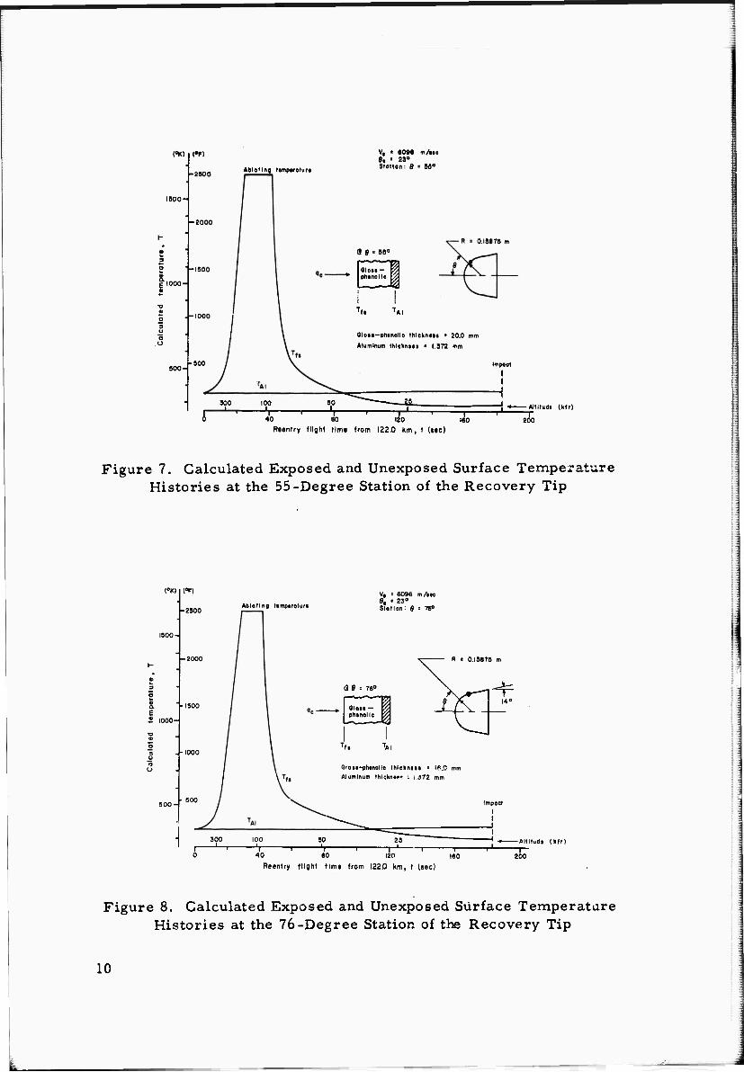
7 Calculated Exposed and Unexposed Surface Temperature Histories at the 55-Degree Station of the Recovery Tip 10
8 Calculated Exposed and Unexposed Surface Temperature Histories at the 76-Degree Station of the Recovery Tip 10
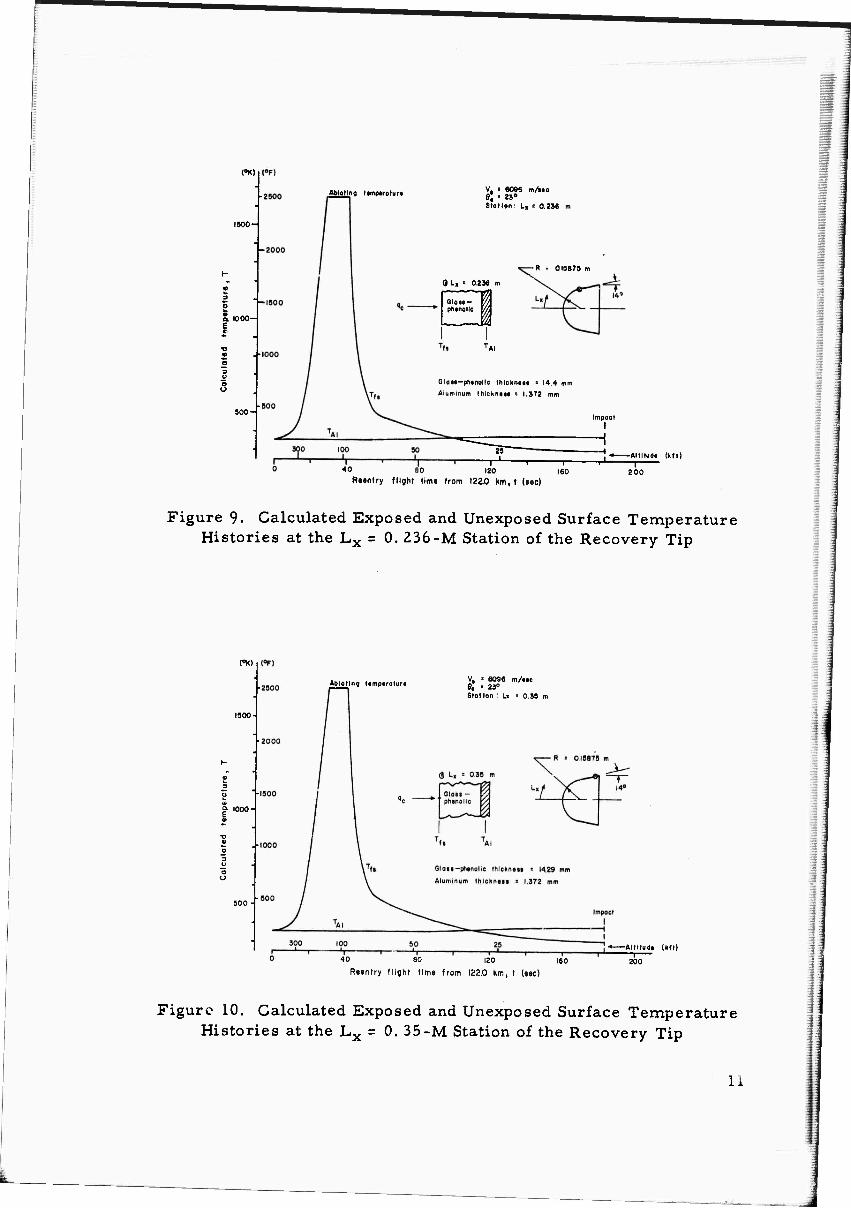
9 Calculated Exposed and Unexposed Surface Temperature Histories at the Lx = 0- 236-M Station of the Recovery Tip 11
10 Calculated Exposed and Unexposed Surface Temperature Histories at the Lx = 0. 35-M Station of the Recovery Tip 11
II Calculated Exposed and Unexposed Surface Temperature Histories on the Bulkhead of the Recovery Tip 12
IV

Page
LIST OF ILLUSTRATIONS (Concluded)
Figure
12 Calculated Exposed and Unexposed Surface Temperature Histories at the Lx = 0.4-M Station of the Destructible Frustum 12
13 Calculated Exposed and Unexposed Surface Temperature Histories at the Lx = 0.75-M Station of the Destructible Frustum .... 13
14 Calculated Exposed and Unexposed Surface Temperature Histories at the Lx = 1.4-M Station of the Destructible Frustum 13
15 Calculated Exposed Surface Temperature Distributions 14
16 Calculated Histories of Ablation Depths for Stations . . 14
17 Calculated Ablation Depths at Three Altitudes Versus Body Station 15
18 Calculated History of Weight Removed by Ablation. . . 15
19 Calculated Total Insulation Thickness Requirements. . 16
20 Calculated Substructure Temperature Histories for Forward Station of Aft Frustum 16
21 Calculated Substructure Temperature Histories for Intermediate Station of Aft Frustum 17
22 Calculated Substructure Temperature Histories for Aft Station of Frustum 17
23 Experimental Thermal Performance of a Reinforced Plastic 24
24 Volume of a Spherical Section 27
25 Linear Variation of Thickness With Length (L) 30
26 Nonlinear Variation of Thickness With Length (L) . . . 31
27 Procedure for Describing a Simple Internal Surface Configuration 33

INTRODUCTION
As a part of the ARPA experimental reentry radar discrimination program, the U.S. Army Missile Command (USAMICOM) bas been engaged in the design and fabrication of several typical, lightweight ICBM reentry vehicles having various ballistic factors. Vehicle No. 1, which is discussed in this report, is a blunt cone, ablative skin vehicle designed to survive intact to an altitude of 30.48 kilometers. At this altitude the forward portion of the vehicle separates xrom the destruct- ible aft frustum. The forward portion of the vehicle is designed to survive to impact so that recorded data can be obtained.
The purposes 01 this report are:
To show the type of reentry environment to which the vehicle is exposed.
To show the calculated ablative heat shield reqa remsnts.
To predict external surface temperatures along the external surface of the blunt cone vehicle.
To assist in determining the criteria for initiating separation of the recovery capsule.
VEHICLE DESCRIPTION AND ENVIRONMENT
The vehicle is a blunt cone having a nose radius of 0. 15875 meter (6. 25 inches) and a cone half angle of 14 degrees (Figure 1). The initial ballistic coefficient, W/CQA, is approximately 537 kg/m2
(110 lb/ft2). The forward portion of the vehicle, termed the recovery tip in Figure 1, contains a tape recorder and associated recovery gear and is designed to survive reentry to impact. The aft portion of the vehicle, the destructible frustum, is designed to fail at a reentry altitude just below 30.48 kilometers (100,000 feet). This type vehicle skin design is advantageous due to the critical weight limitations and other vital criteria specified in the vehicle experiment requirements.
Shielding of the reentry vehicle during ascent by use of a shroud is considered necessary to prevent heat from soaking through the heat shield to vital components before the reentry phase begins. Nominal reentry conditions are 6,096 m/sec (20,000 ft/sec) at an angle of 23 degrees below the local horizon. Shown in Figure 2 are the cal- culated velocity and altitude histories. These trajectory parameters were calculated by the Advanced Systems Laboratory, USAMICOM.

The vehicle spins about its centerline axis, and the initial angle-of- attack is less than 5 degrees.
THEORETICAL PROCEDURES AND BASIC ASSUMPTIONS
Aerodynamic heating to the vehicle was calculated by real gas procedures based on the widely accepted methods of Fay and Riddell, and of Rose, Probstein, and Adams. Aerodynamic heating, ablation, conduction, pressure distribution, and weight calculation procedures used by Stress and Thermodynamics Analysis Branch are described briefly in Appendixes A. B, and C. To obtain a simple internal config- uration on a hemisphere when the external radius and required thick- nesses versus angular station are known, a method was developed whereby the weight is kept to a minimum while the specified thick- nesses are met or slightly exceeded at all spherical stations. This procedure, as explained in Appendix D, is for an internal surface described by a spherical sector with the radius originating on the vehicle centerline.
Temperature limits were set on the aluminum substructure, as determined by the sens-üvity of internal components and the mechan- ical properties of aluminum alloys versus temperature. For the recovery tip the design temperature is approximately 378° K, and for the destructible frustum a design temperature of 478° K was selected. Based on these substructure limits, parameter studies were made for each vehicle station to determine the thickness of ablation material required to limit the aluminum to the specified temperature limits.
Ablation calculations are based on the assumption that the fabri- cated material is of a quality at least equal to that of the "lap-wound" glass-phenolic produced by Westinghouse Electric Corporation and tested in ABMA aerodynamic heating simulation facilities in 1959 and I960.1'2
The initial skin temperature, at the beginning of reentry, was estimated to be 355° K to account for heat radiated in from the shroud during ascent.
The net effects of a small angle-of-attack (5 degrees or less) on the heating to a spinning vehicle are assumed to be negligible so that zero angle-of-attack procedures can be used. Some investigators3
state that this approach is conservative.
\

HFAT SHIELD MATERIALS
The reinforced plastic heat shield selected for Vehicle No. 1 is "lap-wound" glass-phenolic. This material was selected because of its low cost, availability, suitability to tape winding, and adequacy as a h at shield in a relatively mild heating environment.
The lap-winding technique is extremely flexible4 since the lami- nations are parallel to the vehicle centerline and a flat tape is used, 2
The orientation of the tape in relation to the gas flow, though question- able at the beginning in 1958, proved to be of no importance when tested in the severe environment of rocket motor exhaust jets. *'* The ablation results for lap-wound materials were quite comparable with those of tape-wrapped materials having lamiiations making a 20-degree angle with the cone surface (each lamination sloping away from the centerline toward the rear of the vehicle).
Glass-phenolic, asbestos-phenolic., and Thermolag T-2305 were considered for protection of the recovery tip buiinead from base aerodynamic heating. Of these materials the Thermolag T-230, a subliming compound, appears to be the most practical, weightwise. The base region is subjected to low heating rates for a short period of time after separation near 30.48 kilometers. Since the shear and heating are low in the base region, a reinforced plastic is considered unnecessary to prevent pitting and gouging.
RESULTS AND DISCUSSION
1. Aerodynamic Heating
Calculated real gas convective heating rates to a hot wall are presented in Figure 3 for the recovery tip and in Figure 4 for the destructible frustum. Maximum reentry aerodynamic heating occurs near an altitude of 38 kilometers (125,000 feet). The peak heating rates are between 125 X 104 kcal/m2hr on the aft destructible frustum and 650 X 104 kcal/m2hr at the 30-degree station on the hemisphere. The period of significant reentry heating above an altitude of 30.48 kilometers is about 20 seconds. Figure 3 shows that no signifi- cant aerodynamic heating occurs elfter 45 seconds, corresponding to an altitude of approximately 24 kilometers. The calculated hea fluxes on the recovery tip drop quite rapidly after 38 seconds, due to the sharp decrease in velocity resulting from a significant change in ballistic coefficient when the recovery tip separates from the aft frustum.

2. Skin Temperature Histories
Calculated external surface and internal substructure temper- atures are shown in Figures 5 through 14 for several vehicle stations. For the recovery tip (Figures 5 through 10) the substructure tempera- tures peak at or near impact. The calculated bulkhead temperatures are shown in Figure 11 for Thermolag T-230, a subliming material on the outsida of aluminum.
In Figures 12 through 14 are calculated external and internal sur- face temperature histories for three stations on the aft destructible frustum. The aluminum substructure temperature rises rapidly near 40 seconds, due to the recession of the ablation front toward the sub- structure.
Surface temperature distributions at several altitudes are presented in Figure 15. Below an altitude of 40.9 kilometers (134,000 feet) the entire vehicle surface has reached the ablation temperature.
3. Ablation
Ablation-depth histories calculated at selected stations along the vehicle are shown in Figure 16. As expected, the forward stations begin ablating at altitudes above 200, 000 feet and the aft stations begin ablating at altitudes of approximately 150,000 feet. The ablation depths at three altitudes are plotted versus body station in Figure 17. From these ablation depths the weight of ablation material removed versus time or altitude was determined by procedures outlined in Appendixes B and C. Figure 18 shows the calculated ablation weight-loss versus flight time. At 100, 000 feet the total weight of material lost is almost 25 pounds or 15.6 percent of the initial vehicle weight. Approximately 5 pounds have been removed from the recovery tip and 20 pounds from the destructible frustum at 100,000 feet. For a constant CQA this weight loss results in the reduction of the ballistic coefficient from 110 lb/ft2 to approximately 93 lb/ft2.
4. Heat Shield Requirements
The total heat shield requirements necessary to limit the internal substructure to 378° K (220° F) on the iecovery tip and 478° K (400° F) at 100,000 feet on the aft destructible frustum are shown in Figure 19. The calculated glass-phenolic thicknesses are between 14 and 24 millimeters (0. 55 and 0.94 inch) on the recovery tip. Thick- nesses vary from 3 millimeters (0. 118 inch) at the aft end to 4 milli- meters (0. 153 inch) at the fore end of the destructible frustum.

Calculated total heat shield and aluminum substructure weights are tabulated in Table I. The total skin weight required is approxi- mately 65 pounds, of which almost 45 pounds are on the destructible frustum. Seventy percent of the total skin weight is attributed to the glass-phenolic heat shield,
5. Initiation of Separation of Recovery Tip
In determining a criterion for initiation of separation, several devices such as timers, temperature sensors, and deceleration switches were considered. The deceleration or "g" switch was selected as being the most practical. As a result of the variation of "g" levels, aero- dynamic loading, and stibsequent effects of aerodynamic heating on the substructure due to variations in trajectories and vehicle parameters, additional reentry analyses of the destructible frustum became necessary. In addition to the nominal trajectory, minimum and maxi- mum deceleration flights were analyzed. The primary differences in the trajectory parameters were determined by the Advanced Systems Laboratory, USAMICOM, and are shown in Table II.
Calculated aluminum substructure temperatures versus altitude for the destructible frustum are shown in Figures 20, 21. and 22. As anticipated, these data show the substructure temperature, at 30.48 kilo- meters to be highest for the vehicle flying the minimum "g" trajectory. The substructure temperature is lowest at any given altitude for the maximum "g" trajectory. This trend is reasonable due to the large variation in flight time from 100 kilometers to 30.48 kilometers and the time dependence of heat flow through an ablation material having a low thermal diffusivity. The flight time from 100 kilometers to 30.48 kiloxneters is approximately 34, 5 and 25. 5 seconds, respectively, for the minimum and maximum "g" trajectories.
Immediately below an altitude of 30.48 kilometers the substructure temperatures rise sharply. This is primarily due to the proximity of the receding ablation front to the aluminum substructure.
CONCLUSIONS
AMRAD Vehicle No, 1 is exposed to a relatively mild reentry environment. The major portion of the vehicle is exposed to maximum aerodynamic heating rates of 300 X 104 kcal/m2hr or slightly less.

The calculated glass-phenolic heat shield required for Vehicle No. 1 weighs about 46 pounds with 62 percent of this located on the destructible frustum. The aluminum substructure weighs approxi- mately 19 pounds with 87. 5 percent of this located on the destructible frustum.
At any given altitude above 30 kilometers, the calculated sub- structure temperature for the aft destructible frustum increases as the vehicle trajectory goes from the maximum, to nominal, to minimum deceleration cases. The increase in flight time to a given altitude is the major factor in this trend.
Table I. Skin Weights
Vehicle section Aluminum thickness
(in.)
Aluminum weight
(lb)
Heat shield weight
(lb)
Total skin weight
(lb)
Recovery tip
Destructible frustum
0.054
0.054
2.485
16.62
17.423
28.28
*19.908
44.90
*lncludes insulation and substructure on recovery tip bulkhead.
Table II. Relationships Between Maximum and Minimum Deceleration Trajectories Compared With the Nominal
Parameter Maximum "g" Minimum "g"
W/CDA 90% nominal 110% nominal
Reentry velocity 104 % nominal 95%> nominal
Reentry angle 26 degrees 20 degrees
Wind Headwind Tailwind

Recovery tip- • Destructible frustum
0.8666 m
Figure 1. Sketch of AMR AD Vehicle, Number One
(I03 m/.tejidO3 tt/Mc)
(K^m)
60-
4
40
20
(IC?ft)
150
>4-
100 ^
■»0
OX 0±
Ve = 6096 mA« 8, > 23»
Vehicle trojectocy
20
I Recovery tip f trajectory
Recoverable tip ■•-»*• Destructible fruttum
R =015875 tni ,14°
0.2625 m *
40 60 100 140
Reentry flight time from 122.0 km, t (sec)
Figure 2. Reentry Trajectory for Vehicle to 30.48 Kilometers and for Recovery Tip to Impact

\ m'hry
P. ZOO-
/ etu \
V, ■ 6096 m/uc 9, • ZJ» Material glow- phtnofic
Altitude (kit)
R»tntry flight tim« from 1220 Km, t («€c)
Figure 3. Calculated Convective Heating Rates for Recovery Tip
4 Kcol\ / Btu
n^hr/ V'
200-
V, = 6096 m/»«c 8e ■ 23» Material: glatt-phtnallc
300 -T—
10
ZOO
T" l90 -—Altitude (kft)
F Reentry flight time from 122.0 km, f (sec)
Figure 4. Calculated Convective Heating Rates for Destructible Frustum
8

CK)
IBOO-
■2000
1000-
900-
■1000
Abtotlng ttmpTotuft
V, = 6096 HVMC
e, ■- Sä" Station : Ä = 0»
0I987S m
GloM-phtnolic thlcKnsn - 240
Aluminum thlcknttl - 1.372 mm
100 50 -s— 80
25
40 80 120
Reentry flight time frotr I2Z.0 Km, t (see)
-i— 160
Impact
- Allltuda (Kit) —r
200
Figure 5. Calculated Exposed and Unexposed Surface Temperature Histories at the Stagnation Point of the Recovery Tip
Abloting Umptrqturt
Vi = 6096 m/ltc e ' 23° Station: 0 ■ 30°
R = 0.IS879
Slou-plionoMc thlckm»! ■ 220
Aluminum thlcltnott = 1.372 mm
1 1 j— 80 120 160
Reentry flight time from 122.0 hm, t (sec)
Impact \ I 1
-• ■«—Altllud» (kft)
200
Figure 6. Calculated Exposed and unexposed Surface Temperature Histories at the 30-Degree Station of the Recovery Tip
CK)
1800-
S glOOO-
500-
(0F)
AblaMng t«mp«rolur«
Vt i 6096 m/ito 8« • 23° Station: 8 • 8«°
300
0,13873 m
9 9 = 88°
phtnolfe Z Qlois
'Al
Glaii~ph«nollc thlchnaii a 20.0 mm
Aluminum thlcknlli = 1,372 mm
100 —L. -i r^ 1—
40 60 120 Reentry flight time from 122.0 km, t (tec)
80 160
-Altltudt (kit)
200
Figure 7. Calculated Exposed and Unexposed Surface Temperature Histories at the 55-Degree Station of the Recovery Tip
(0K)
1000-
t«FI
Ablating ltmp«ralurt
V, ■ 6096 m/iK 8, ■ 23° Stotion: 8 ■ 76°
\ R = 0,18675 m
17 A - 7cO \ J_
QlQtl — ^ phenolic 7/
i
4 \ t 14»
T 1
fl TAI
C ton-ptwrotic
lumtnum thick
thickn«»« =
n«- - t.,572
ISO mm
mm
Impact
120
-Alllluda (ktl)
Reentry flight time from 122,0 km, t (sec)
Figure 8. Calculated Exposed and Unexposed Surface Temperature Histories at the 76-Degree Station of the Recovery Tip
10
5. 1000- E
a
1 5
Ablallno (tmpiroturi V. ■ 609B m/i«c e, ■ a0
Station: I, i 0.23« m
-R = 0.15875 m
0 L, • 0 236 m
Glatt- phtnüllc l
I TAI
Glan-phtnollc thlckntu » 14.4 mm
Atumtnum thictntlt a 1,372 mm
Impoct I
r *0 SO 120 |60
Rtontry flight time from 122.0 km,t («ec)
, «—Altitudt (kit) TJ 1
Figure 9. Calculated Exposed and Unexposed Surface Temperature Histories at the Lx = 0. 236-M Station of the Recovery Tip
(°K)
| 1000
Ablating ttmptratura V, > 6096 m/tic 8, ■" 23° Station : U ' 0.39 m
40 80 120 160
Reentry flight time from 122.0 km, t (sec)
Altltudt (Ml)
Figure 10. Calculated Exposed and Unexposed Surface Temperature Histories at the Lx = 0. 35-M Station of the Recovery Tip
li

(0K)|(<>F)
V, = «09« m/„c 8, = 23»
■ R ■ O.I5«7S m
^ 340 ^„o
T-230"l>>liiiin«l = l.rBS mm Algmlrum ihleKnt.. r 0,111 mm
Altlludi (kft) 80 120
Re«n(ry flight time from 122.0 Km, t (sec) 200
Figure 11. Calculated Exposed and Unexposed Surface Temperatur« Histories on the Bulkhead of the Recovery Tip
V, = 603« m/Me 9, • 23» Stollon: L,! 0.40 m
«blolln« ttmp.rolur.
10° " Altltudt (Hft)
Reentry flight time from 122.0 km, t (sec)
Figure 12. Calculated Exposed and Unexposed Surface Temperature Histories at the Lx = 0.4-M Station of the Destructible Frustum
12

PK) CF)
2500
1500
Vt ■ 60S* ITI/MC 9, » 23" SMIWi : L, • 0.75 I
Abloiin« wnptrature
20 30 Retntry flight time from 122.0 l.m, t (MC)
"!0 -«—Altitudi (kit)
Figure 13. Calculated Exposed and Unexposed Surface Temperature Histories at the Lx = 0. 75-M Station of the Destructible Frustum
(•K) CF)
2500
| 3
V, . 6096 m/HC 9, ■ 23' Station : L, = 1.4 m
8 lx r 14 m
Glass- phenol.c
SUMS-plitnolic thickntss ■ 2.97 mm Aluminum thickntss s 1.372 mm
Ablating »mparature
10 20 30
RMItry flight time from 122 0 Km, t (sec)
100 ♦-Aifiigd, (km
Figure 14. Calculated Exposed and Unexposed Surface Temperatur« Histories at the Lx = 1. 4-M Station of the Destructible Frustum
13

a
ItOO-
1200
<V>
MOO
V, • MM m/.tc 0, ■ f S« MottrM: glat pmitolic
AMatüif Nnwtronn ■ i«4S*K
•00
I I 0
Body •totion, Lt/H
Figure 15. Calculated Exposed Surface Temperature Distributions
(mm) (in)
I'
V, • «096 m/ttc e, • «• Mowiol1 "lap-«mind" gluu-pNinllc
Statten
9 . o* SO*
7«» Lx • 0 236 m
0.79 m 1.40 m
"ST Retmry flight lime from 122.0 Km, t (MC)
Figure 16. Calculated Histories of Ablation Depths for Stations
14 V

VB ■ 6096 tti/f« 8, ■ ii' Madrid; "top-wound" gioM-ptenoüc
R = 0.I587S (In)
>04
i '4 3
* 6 Body »tation, L./R
Figure 17. Calculated Ablation Depths at Three Altitude! Versus Body Station
V, = 6098 m/i«c
Moterlo: : "lop-wound" glotl - ph.nollc
Altltud« (kfl)
Reentry flight time from 122.0 Km , t (sec)
Figure 18. Calculated History of Weight Removed by Ablation
15

(mm)
I I I e h-^t
V- « 6096 m/»« Ö, - 23» Mpttriol:"fap - wound" glai» -phtnolic
(Tongtnt point) A
^
Body station, Lx/R
Figure 19. Calculated Total Insulation Thickness Requirements
(•K) CF)
I
8, ■ 39 mm 80 = 1.372 mm
A Minimum dftitration
O Nominal decoltration
D Maximum ätctltration
Altitude, Y
Figure 20, Calculated Substructure Temperature Histories for Forward Station of Aft Frustum
1ft

(•K) CF) Lx = 0.75 m
82 ■ 1.372 mm
A Minimum dtcttorotion
O Nominot deceltration
Q Maximum dtciltration
110 100 (kfl) 1 1 ' 1 ' I 1 1
30 (Km)
Altitude. Y
Figure 21. Calculated Substructure Temperature Histories for Intermediate Station of Aft Frustum
{»K) CF) 81 ■ 2.P7 mm 80 = I.37Z mm
A Minimum dKMrotion
O Nominal dtcjitration
Q Maximum dvcvMration
Altitude, V
Figure 22. Calculated Substructure Temperature Histories for Aft Station of Frustum
17

LITERATURE CITED
l- Selected Concepts for a NIKE ZEUS Target Vehicle. ABMA Report RJ-TM-1-60, 23 September I960.
2 Edgewinding and Lapwinding Techniques for Heat Shield Fabrication, Westinghouse Report 608, DA-36-061-ORD-608, 31 October I960.
3- Low-Observable Reentry Vehicle Program, AVCO Report RAD-SR'-63-10, 31 January 1963 (Secret).
4. "Lap Winding Is Best for Cones," American Machinist/Metalworking Manufacturing, 2, Vol. 105, No. 15, pp 83, 84, 24 July 1961.
5. Properties of "Thermo-Lag" T-230 Ex 165 Subliming Compound, Emerson Electric Report 1141.
6. C. H. Lewis and E. G. Burgess. Ill, Charts of Sphere Stagnation Heat Transfer Rate in Air and Nitrogen at High Temperatures, AEDC-TDR-63-139, July 1963.
7. P. H. Rose, R. F. Probstein, and M. C. Adams, Turbulent Heat Transfer Through a Highly Cooled Partially Dissociated Boundary Layer, AVCO Research Report 14, January 1958.
8. L. T. Allen, Stagnation Point Heat Flux on a Sphere Moving With Hypersonic Velocities. ABMA Report DA-TN-53-58, August 1958.
9. R. Chapkis and M. Tauber. Aerodynamic Pressure Distribution Handbook, Boeing D2-5887, 1960-1961.
10. C. F. Hansen, Approximations for the Thermodynamic and Transport Properties of High Temperature Air, NASA TR-R-50, 1959.
11. J. Hilsenrath, M. Klein, and H, Woolley, Tables of Thermo- dynamic Properties of Air Including Dissociation and lonization From 1500 K to 15,000 K, AEDC TR-59-20, December 1959.
12. H. A. Millinger, Performance of Nose Cone Reentry Protection of JUPITER C R5-40 (U), ABMA Report DS-TN-116, 1957 (Confidential).
18

LITERATURE CITED (Concluded)
13. W. B, Schölten, Evaluation of the Thermal Performance of the Ablation Materialp on Recovered JUPITER IRBM Reentry Nose Cones (U), ABMA Report DSD-TR-6-60, January I960 (Secret).
14. W. G. Burleson, Comparisons of Measured Flight Temperatures and Ablation Data With Theoretical Results for Widely Varying Flight Environments (U). USAMICOM Report RS-TR-63-10. December 1963 (Confidential).
15. R. L. O'Neal and L. Rabb, Heat-Shield Perfurmance During Atmospheric Entry of Project MERCURY Research and Develop- ment Vehicle, NASA TM-X-490, May 1961 (Confidential).
19

SELECTED BIBLIOGRAPHY
1. Preliminary Specifications for Reentry Trajectories and Vehicles for AMRAD Phase I, MIT-Lincoln Laboratory Draft, 5 April 1962.
2. "The Problem of Aerodynamic Heating, " E. R. Van Driest, Aeronautical Engineering Review, October 1945.
3. A Manual for Determining Aerodynamic Heating of High Speed Aircraft, Bell Aircraft Corp. Report No. 7006-3352-001, June 1959.
4. A Study of the Motion and Aerodynamic Heating of Ballistic Missiles Entering the Earth's Atmosphere at High Supersonic Speeds, NACA Report No. 1381, 1959.
5. Fundamentals of Aerodynamic Heating, R. W. Truitt, The Ronald Press Co. , I960.
6. Some Aerodynamic Heating Considerations for NIKE ZEUS IRBM Target Missiles (U), DSD-TR-6-60, 13 April I960.
7. Preliminary Aerodynamic Heating Analysis for a PERSHING l3/4 Missile (U), USAMICOM Report No. RS-TN-62-1. 9 February 1962.
8. Calculated Aerodynamic Heating Effects on an IRBM JUPITER All-Plastic Nose Cone (U), ABMA Report No. RS-TN-2-61, 8 February 1961.
9. Handbook of Astronautical Engineering, H. H. Koelle, McGraw Hill Book Co., Inc., N. Y. , 1961.
10. Heat and Mass Transfer, E. R. G. Eckert and R. M. Drake, McGraw-Hill, N. Y. , 1959.
11. Progress in International Research on Thermodynamic and Transport Properties, ASME, Academic Press, N. Y. , 1962.
12. Numerical Methods for Transient Heat Flow, G. M. Dusinberre, Transactions of the A. S. M. E. , November 1945.
13. Heat-Transfer Calculations by Finite Differences, G. M. Dusinberre, International Textbook Co. , Scranton, Pa., 1961.
20

SELECTED BIBLIOGRAPHY (Continued)
14. A Method of Computing the Transient Temperature of Thick Walls from Arbitrary Variation of Adiabatic-Wall Temperature and Heat-Transfer Coefficient. NACA Report No. 1372, 1958.
15. Measurements of Heating to a Thermally Thick Spherical Copper Calorimeter, RSM-TM-1-60, 17 October I960. "~"
16. Results of Heat Flux Calibration Tests Performed on the Various ABMA Reentry Aerodynamic Heating Simulation Facilities (U), DSD-TM-20-58, 2 June 1958.
17. Some Ablation Results Obtained in ABMA Aerodynamic Heating Simulation Facilities (U), DSD-TR-6-58, 25 July 1958. "~
18. A Preliminary Evaluation of Thermal Insulation Applied by T.-pe Wrapping Techniques (U), DSN-TM-4-60, 25 March I960.
19. Thermal Physical Property Compilation for Missile and Aircraft Structural and Insulating Materials, Martin Report No. OR-520, Rev. 1, 18 July 1961.
20. Comparison of 1750 NM JUPITER Reentry Flight Conditions to Those of ABMA Aerodynamic Heating Simulation Facilities (U), DSD-TN-63-58, 19 November 1958.
21. Estimated Thermal Protection Requirements for a Low Decele- ration Satellite Reentering the Earth's Atmosphere (U), MNM-M-S&M-P-1-60, 11 July I960.
22. Pressure Measurements on Sharp and Blunt 5° and 15° Half- Angle Cones at Mach Number 3. 86 and Angles of Attack to 100°, J. L. Amick, NASA-TN-D-753, February 1961.
23. "Experiments on Circular Cones at Yaw in Supersonic Flow, " M. Holt and J. Blackie, Jr. , Journal of the Aeronautical Sciences, October 1956.
24. Generalized Heat Transfer Formulae and Graphs, R. W. Detra and H. Hidalgo, AVCO Research Report No. 72, March I960.
25. Effect of Angle Attack on Laminar Convective Heat Transfer on Sharp and Blunt Cones, A. E. Heins and T. J. Estes, GE Report No. 615D70.
21

SELECTED BIBLIOGRAPHY (Concluded)
26, "Theory of Stagnation Point Heat Transfer in Dissociated Air, " J. A. Fay and F. R. Riddell, Journal of the Aeronautical Sciences, Vol. 25, No. 2, pp 73-85, February 1958.
27. "Laminar Heat Transfer Over Blunt-Nosed Bodies at Hypersonic Flight Speeds, " L. Lees, Jet Propulsion, Vol. 26, No. 4, pp 259■■274. April 1956.
22
Appendix A
USAMICOM AERODYNAMIC HEATING METHODS
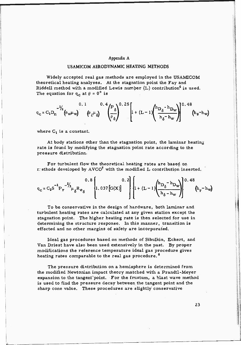
Widely accepted real gas methods are employed in the USAMICOM theoretical heating analyses. At the stagnation point the Fay and Riddell method with a modified Lewis number (L) contribution6 is used. The equation for qc at Ö = 0° is
-X/t 0. 1 0.4
qc=C1Dn (p^^ (pffx^
0.25
1+(L-1) -hDw\
0.48
(hs~hw)
where Qx is a constant.
At body stations other than the stagnation point, the laminar heating rate is found by modifying the stagnation point rate according to the pressure distribution.
For turbulent flow the theoretical heating rates are based on r.'ethods developed by AVCO7 with the modified L contribution inserted.
qc=C2S Pr u R,
0.8 0.2
1.037[G(X)] 1+(L-1)
0.48
(Vhw)
To be conservative in the design of hardware, both laminar and turbulent heating rates are calculated at any given station except the stagnation point. The higher heating rate is then selected for use in determining the structure response. In this manner, transition is effected and no other margins of safety are incorporated.
Ideal gas procedures based on methods of Sibulkin, Eckert, and Van Driest have also been used extensively in the past. By proper modifications the reference temperature ideal gas procedure gives heating rates comparable to the real gas procedure. 8
The pressure distribution on a hemisphere is determined from the modified Newtonian impact theory matched with a Prandtl-Meyer expansion to the tangent'point. For the frustum, a blast wave method is used to find the pressure decay between the tangent point and the sharp cone value. These procedures are slightly conservative
23
il

compared^athe GASL 3-D method of characteristics.9 Results from the blunt cone pressure routines used herein have been favorably com- pared with experimental pressure data.'
The viscosity, compressibility factor, specific heat ratios, local enthalpy, local temperature, local speed of sound, and local density are taken from data published by C. G. Hansen10 and J. Hilsenrath.11
On the hemisphere a modified Newtonian flow theory is used to determine the velocity gradient.
Before and after ablation, a forward finite difference heat conduc- tion procedure is used. During ablation a special conduction procedure applicable to conduction in a material having a receding surface is utilized. Both of these procedures compare well with exact solutions.
Ablation of material in flight is based on experimental results of material performance tests in liquid propellant rocket motors. The average effective heat of ablation, H^, versus heating rates (Figure 23) is determined by use of ablation depth measurements and metallic calorimeters.
o
o
o I
Heat flux to nonablating surface at the ca'atlng temperature
Figure 23. Experimental Thermal Performance of a Reinforced Plastic
24
k.

Ablation and calibration models used in thy tests had tip diameters from 19.05 to 635 millimeters. The stagnation temperatures were from 1920° to 4700° K and the pressures were between 70,000 and 105,000 kg/m2. Hot wall heat fluxes ranged between 50 X 104 and 2000 X 104 kcal/m2hr.
Even though the rocket motor exhaust gas composition differs con- siderably from air, excellent flight and theoretical ablation correlations have been obtained using this semiempirical method. One subscale and three full-scale IRBM vehicles flying near Mach 15 were recovered after flight and measured for material removal during the JUPITER research and development program. ^ 13'14 These ablation depth corre- lations were for glass-melamine, glass-phenolic, refrasil-phenolic, and asbestos-phenolic materials. The flight ablation depths of all four materials agreed very closely with the predicted values, especially on the hemispherical portion of the blunt cones.
Good comparisons have also been obtained between theoretical and flight data for the heat shield on a BIG JOE capsule reentering the earth's atmosphere approximately 6, 096 m/sec.14'15
25

Previous page ^as blank, therefore not filled.
Appendix B
VOLUME OF HEMISPHERICAL SECTION
Often in heat transfer work and in the design of blunt vehicles, it is necessary to calculate the weight of material removed by ablation or to determine the entire skin weight of hemispherical tips. To obtain the weight it is required that the volume be known.
The volume of the spherical section shown in Figure 24 is readily computed with the following equation:
Vt -- Z*A6 I [R206n - R062
n + 63n/3j sin 0n
n= 1 (i)
:::^
Figure 24. Volume of a Spherical Section
This equation is derived as follows:
x is the radius vector to the center of gravity of the incremental area
27
y-

;
y = x sin 9 is the moment arm
dA = xd0dx is the incremental area
dV = 27rydA = ZTTX2 sin ÖdÖdx
:. Vt = ZTT I I xz sin 0d0dx Je = ü
0 JR0 - 6
Zn *,e = * | Wo - (Ro " ö)3]sin ödö
Je = o0 3 '0 = 0 (2)
n = (t>/A0 r , Vt = ZnAe I [R2
06n - R062r, + 63
n/3j sin 0n (3)
By proper selection of the incremental angle, A0, commensurate with the particular variation of wall thickness, accurate volumes on a spherical tip can be obtained by use of Equation (3). The thickness 6 , measured normal to the external surface, is the average thickness over the A0 at increment n.
28

Appendix C
VOLUME CALCULATION FOR FRUSTUMS OF RIGHT CIRCULAR CONES
Equations determining the volume for frustums of right circular cones were derived using Pappus' second proposition;
"If a figure of area A revolves about an axis in its plane but not cutting it, then for a complete revolution, the volume of the solid generated is:
V = 27ryA (4)
where y is the distance from the axis to the center of gravity of A. "
The frustum volume equations were deduced for a linear and a nonlinear variation of skin thickness, 6, with length, Lx.
1. Linear Variation of Thickness With Length
The volume of the frustum of a right circular cone having a linear variation of thickness with length, Lx, may be calculated by adding the volume of the solid generated by the rectangular area "A" (Figure 25) to the volume of the solid generated by the triangular area "B" in the following manner:
For area "A" the volume is
VA = 27r62Lx
Jx R sin 0 + —- cos 0 sin 0
and for area "B" the volume is
VB= 2 U
R sin Ö + —- c os 6 - (ox + il^ii) sin
Combining Equations (5) and (6) gives the total volume, V^.
Vt = ^(-^-ij R sm 0 + (-i-^ij [—) cos 6
\ 61 + 62 /
sin Q
(5)
(6)
(•7)
29

Figure 25. Linear Variation of Thickness With Length (L)
2. Nonlinear Variation of Thickness With Length
The volume of the frustum of a right circular cone having a nonlinear variation of thickness with length can be calculated from the following equation where n is the increment being considered in the x direction:
n = x^/Ax Vt = 27rAx T
n = 1 R6n +
cos gxn 6n sin2 0
6^ (8)
30

In deriving Equation (8) (Figure 26):
The incremental area is dA = ödL
The moment arm is yc
The incremental volume is dV = 27ryc6dL
—<L
Figure 26, Nonlinear Variation of Thickness With Length (L)
Other pertinent equations are:
dL = dx
sin 0
Yj = R sin ß
Y2 = Yj + x cot 9
31

Yr = Y2 - ^ sin 9
.". Y = R sin Ö + x cot 0 - - sin 0 C Ci
Equation (8) can be used to accurately determine the volume of ablation material removed due to hypersonic flight in the atmosphere and the volume of an entire frustum of nonlinear thickness with length.
32

Appcrdix D
SIMPLE INTERNAL SURFACE DESCRIPTION FOR A HEMISPHERICAL TIP HAVING A SKIN THICKNESS VARYING WITH ANGULAR STATION
In the design of reentry vehicles, it is frequently desirable or necessary to deviate slightly from optimum ablation material or heat- sink thickness requirements on a hemispherical tip to simplify the internal surface configuration. A simple internal configuration is advantageous due to reduced costs of fabrication, especially for ve- hicles that are to be produced only in limited numbers.
For a given external spherical configuration and for known skin thickness requirements varying with angular stations (Figure 27), a procedure has been derived for determining an internal surface cor.- figuration described by a spherical sector with the radius originating on the vehicle centerline.
Figure 27. Procedure for Describing a Simple Internal Surface Configuration
Known parameters required for solution of the internal configura- tion are (Figure 27):
33

R0 - External radius
6) - Skin thickness measured normal to the external surface at any known d\
6% — Skin thickness measured normal to the external surface at any known ö2
It is required to find:
Center location, C, on the centerline for the internal surface
Internal surface radius, Rj
Calculated skin thicknesses at any desired angular station
With the known parameters listed in Figure 27 let
^i = (Ro - 6i) cos 0j
X2 = (Ro - 62) cos 02
Yi = (Ro - 61) sin 0!
Yz = (Ro - 62) sin 02
Then from triangle ACD
yj + (Xi + Ax)2 = R- (9)
and from triangle BCE
y|+ (X2 +Ax)z = Rl (10)
Solving Equations (9) and (10) simultaneously results in
yf - y| + (xj + Ax)2 - (x2 + Ax)2 = 0
or
and
(xf + yl) - (x2 + y2) + 2Ax(x1 - x2) = 0 (11)
Ax=(x2 + y|)-(x! + yf) 2(x1-x2)
v ;
34
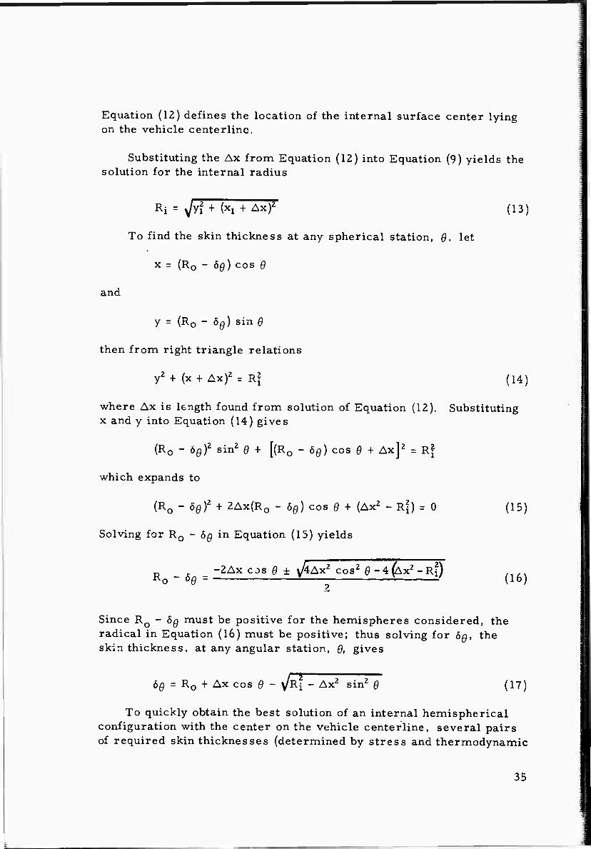
Equation (12) defines the location of the internal surface center lying on the vehicle centerline.
Substituting the Ax from Equation (12) into Equation (9) yields the solution for the internal radius
Ri = yjyl + fo + Ax)2 (13)
To find the skin thickness at any spherical station, Q, let
x = (R0 - 6^) cos 0
and
y = (RQ - 00) sin 9
then from right triangle relations
y2 + (x + Ax)2 = Rf (14)
where Ax is length found from solution of Equation (12). Substituting x and y into Equation (14) gives
(R0 - 6Q)Z sin2 6 + [(RQ - 6Ö) cos 0 + Ax]2 = R?
which expands to
(R0 - öQ)2 + 2Ax(R0 - 6Q) COS 9 + (Ax2 - R?) = 0 (15)
Solving for R0 - 6^ in Equation (15) yields
_ . -2Ax cos 9 ± v/4Ax2 cos2 0-4^x2-Ri) .1/x R0 - öö = 1 S^ f (16)
Since R0 - 6^ must be positive for the hemispheres considered, the radical in Equation (16) must be positive; thus solving for 6Q, the skin thickness, at any angular station, 9, gives
6Ö = R0 + Ax cos 9 - v/Ri - Ax2 sin2 9 (17)
To quickly obtain the best solution of an internal hemispherical configuration with the center on the vehicle centerline, several pairs of required skin thicknesses (determined by stress and thermodynamic
35

analyses) at known angular stations are investigated by use of a high- speed digital computer. The calculated skin thickness obtained from the computer program for each internal surface configuration (one configuration for each pair of skin thicknesses input to the program) is compared with known skin thickness requirements previously deter- mined from stress and thermodynamic analyses.
Selection of the best internal surface configuration is then made from the skin thickness comparisons by considering primarily the effects of skin thickness deviations on accomplishment of the mission and the effects of skin thickness deviations on the total weight of the hemispherical section.
With the skin thickness incorporated as an output to the configura- tion procedure, the weight of the material on a hemisphere is readily obtained by use of the volume equations presented in Appendix B.
36

UNCLASSIFIED Security Classification
DOCUMENT CONTROL DATA - RiD (Security ctaaaittc/ttion ot titlm, body of abstract and indexint Mnnotaliotl must be entered when the overall repo-t is ciasstlied)
1 O^lnlNATING ACTIVITY fCo/po/ste aylhor) Structures and Mechanics Laboratory Directorate of Research and Development U. S. Army Missile Command Redstone Arsenal. Alabama
2a REPORT SECURI TV C L ASSI FIC A TrON
Unclassified 2b GROUP
3 REPORT TITLE THEORETICAL EFFECTS OF REENTRY AERODYNAMIC HEATING
ON THE EXTERNAL SKIN STRUCTURE OF AMRAD EXPERIMENT NUMBER ONE
4 DESCRIPTIVE NOTES (Type ot report and inclusive dales)
5 AUTHORfS; (Last name, first name, initial)
Burleson, W. G. and Reynolds, R. A.
6 REPORT DATE
30 April 1965 Sa CONTRACT OR GRANT NO.
ij. PROJECT NO
AMC Management Structure Code No, 5900.21.16229
7a TOTAL NO. OT PASES
38 7 fa. NO. OF REFS
15 9a. ORIGINATOR'S REPORT NUMBERfSJ
RS-TR-65-3
9b. OTHER REPORT NOfS) (A ny other numbers that may be assigned this re pott)
AD 10. A VAIL ABILITY/LIMITATION NOTICES
Qualified requesters may obtain copies of this report from DDC.
II. SUPPLEMENTARY NOTES 12 SPONSORING MILITARY ACTIVITY
Same as No. 1
13 ABSTRACT
Calculated reentry aerodynamic heating effects on the external skin of an ICBM reentry test vehicle having a relatively low weight-to-drag ratio are presented in this report. The vehicle is a blunt cone with the aft portion designed to fail just after maximum heating and the forward portion designed to survive to impact.
The tape-wound, reinforced plastic heat shield is subjected to maximum reentry heating rates between 125 x 104 and 650 x 104 kcal/m2hr. Resulting external and internal surface temperature histories are given. Effects of extreme trajectory, vehicle characteristics, and atmosphere variations on the aluminum substructure temperature histories are discussed.
DD .Ä 1473 UNCLASSIFIED Security Classification 39

UNCLASSIFIED Security Clcissificdlion
KEY WORDS LINK C
HOLE WT
Reentry vehicle
Heat shield materials
Surface temperature histories
Destructible frustum
Recovery tip
INSTRUCTIONS
1. ORIGINATING ACTIVITY: Enter the Ruine and address of the contractor, subcontractor, grantee, Department of De- fense activity or other organization (corporate author) issuing the report.
2a. REPORT SECURTY CLASSIFICATION: Enter the over- all security classification of the report. Indicate whether "Restricted Data" is included. Marking is to be in accord- ance with appropriate security regulations.
2ft. GROUP; Automatic downgrading is specified in DoD Di- rective 5200.10 and Armed Forces Industrial Manual. Enter the group number, Also, when applicable, show that optional markings have been usedfor Group 3 and Group 4 as author- ized.
3. REPORT TITLE: Enter the complete report title in all capital letters. Titles in all cases should be unclassified. If a meaningful title cannot be selected without classifica- tion, show title classification in all capitals in parenthesis immediately following the title.
4. DESCRIPTIVE NOTES: If appropriate, enter the type of report, e.g., interim, progress, summary, annual, or final. Give the inclusive dates when a specific reporting period is covered.
5. AUTHOR(S): Enter the name(s) of authoKs) as shown on or in the report. Enter last name, first name, middle initial, If military, show rank and branch of service. The name of the principal author is an absolute minimum requirement.
6. REPORT DATE: Enter the date of the report as day, month, year; or month, year. If more than one date appears on the report, use date of publication.
7s. TOTAL NUMBER OF PAGES: The total page count should follow normal pagination procedures, i.e., enter the number of pages containing information.
76. NUMBER OF REFERENCES; Enter the total number of references cited in the report
8fl. CONTRACT OR GRANT NUMBER: If appropriate, enter the applicable number of the contract or grant under which the report wa? written,
86, 8c, 8t 8d. PROJECT NUMBER; Enter the appropriate military department identification, such as project number, subproject number, system numbers, task number, etc.
9a. ORIGINATOR'S REPORT NUMBER(S): Enter the offi- cial report number by which the document will be identified and controlled by the originating activity. This number must be unique .o this report.
96. OTHER REPORT NUMBER(S); If the report has been assigned any other report numbers (either by the originator or by the sponsor), also enter this numberCs).
10. AVAILABILITY/LIMITATION NOTICES; Enter any lim- itations on further dissemination of the report, other than those imposed by security classification, using standard statements such as:
(1) "Qualified requesters may obtain copies of this report from DDC "
(2) "Foreign announcement and dissemination of this report by DDC is not authorized."
(3) "U. S. Government agencies may obtain copies of this report directly from DDC. Other qualified DDC users shall request through
(4) "U. S. military agencies may obtain copies of this report directly from DDC Other qualified users shall request through
>■
(5) "All distribution of this report is controlled. Qual- ified DDC users shall request through
tf the report has been furnished to the Office of Technical Services, Department of Commerce, for sate to the public, indi- cate this fact and enter the price, if known.
11. SUPPLEMENTARY NOTES: Use for additional explana- tory notes. 12. SPONSORING MILITARY ACTIVITY: Enter the name of the departmental project office or laboratory sponsoring (pay- ing lor) the research and development. Include address. 13. ABSTRACT; Enter an abstract giving a brief and factual summary of the document indicative of the report, even though it may also appear elsewhere in the body of the technical re- port. If additional space is required, a continuation sheet shall be attached.
It is highly desirable that the abstract of classified re- ports be unclassified. Each paragraph of the abstract shall end with an indication oLthe military security classification of the information in the paragraph, represented as (TS), (S), (C). or (U).
There is no limitation on the length of the abstract. How- ever, the suggested length is from 150 to 225 words.
14. KEY WORDS: Key words are technically meaningful terms or short phrases that characterize a report and may be used as index entries for cataloging the report. Key words must be selected so that no security classification is required. Iden- fiers, such as equipment model designation, trade name, mili- tary project code name, geoRraphic location, may be used as key words but will be followed by an indication of technical context. The assignment of links, rules, and weights is optional.
40 UNCLASSIFIED Security Classification