theoretical and experimental stress analyses of ornl thin
TRANSCRIPT
\K i^' . ' — '•''}£* ORNL-5019
Theoretical and Experimental Stress Analyses of ORNL Thin-Shell Cylinder-To-Cylinder
Model 4
R. C. Gwaltney S. E. Bolt J. W. Bryson

^f^yw^m^^^mm^^-nv^mm-m^^ -^ - :^~
BLANK PAGE
> v,. .-*-.-. v..-.. • -••-;-...••:••.. . ^ i ^ V S ^ l W I B W W ! * * * ^ " "^-' • i ' " ' -

Printed in the United States of America. Available from National Technical Information Service
U.S. Department of Commerce 5285 Port Royal Road. Springfield. Virginia 22161
Price: Printed Copy S7.60; Microfiche S2.2S
This report was prepared as an account of work sponsored by the United States Government. Neither the United States nor the Energy Research and Development Administration, nor any of their employees, nor any of their contractors, subcontractors, or their employees, makes any wa'ranty. express or implied, or assumes any legal liability or responsibility for 'he accuracy, completeness or usefulness of any information, apparatus, product or process disclosed, or represents that its use mould not mfr;nge privately owned rights.

ORHL-5019 UC-79, -79b, -79k
Contract No. W-7W5-eng-26
Reactor D i v i s i o n
THEORETICAL AND EXPERIMENTAL STRESS ANALYSES OF CRKL THIN-SHELL CYLINDER-TO-CYLINDER MODEL k
R. C. Gwaltney S. E. B o l t J . W. Bryson
a* aa by * c I M u *
of thai
Eacqpr aoraajraf
ot leaaooaMfcy f d the aocwacy of «wy mtmwmtkm, affntmt, •reowct or
I, or ttpuMMU dM in we
JUNE 1975
OAK RIDGE NATIONAL LABORATORY Oak Ridge, Tennessee 3783O
operated by UNION CARBIDE CORPORATION
for the U.S. ENERGY RESEARCH AND DEVELOIMENT ADMINISTRATION
y-\

I l l
C-JBTSHTS
ABSTRACT 1
1 . EfTRODUCTIOH 1
2 . EXPERIMENTAL ANALYSIS 4
2 . 1 !fodel Construction 5 2 .2 Strain-Gage Layout 5 2 .3 Vest Description 8 2.4 Data Acquisi t ion and Reduction 13 2.5 Vsr ia t ions of Maxisun Measured S t resses Around
Nozzle-Cylinder Junct ion II* 3 . FINITE-ELEMENT ANALYSIS £3
3.1 Sackground 23 3.2 Finite-Element Method 2k 3.3 Finite-Element Idea l i za t ion of Model 30
4. COMPARISON OF THEORY A?ffi EXPERIMENT 32 4 . 1 In te rna l Pressure 22 U.2 Out-of-Plane Moment Loading, M ^ , on Nozzle 3** 4.3 Torsional Moment Loading, M_,, on Nozzle 3U 4.4 In-Plane Moment Loading, M™, on Nozzle 35 4.5 In-Plane force , Fy„, on Nozzle 35 4.6 Axial Force, F™, on Nozzle 36 4.7 Out-of-Plane Force, F„ N , on Nozzle 36 4.8 Torsional Moment Loading, I t . - , on Cylinder 37 4 .9 Out-of-Plane Moment Loading, M^,. on Cylinder 37 4.10 In-Plane Moment Loading, VL-, on Cylinder 33 4.11 Axial Force, F x c , on Cylinder 36 4.12 In-Plane Force, ?.._, on Cylinder 38 4.13 Out-of-Plane Force, F z c , on Cylinder 39
5 . CONCLUSIONS 39
ACKNOWLEDGMENTS 42
REFERENCEC 108
APPENDIX. TABULATION OF EXPERIMENTAL DATA I l l

THEORETICAL AND EXPERKHrTAL STRESS AHAL3T££S OF OiWL THIM-SKELL CYLaDER-TO-CYLIHDEP. MOL-EL k
R. C. Gwaltney S. £. Bolt J . V. Bryson
ABSTRACT
The Last in a ser ies of fcur th ' f . - sae i l cy l inder-tc-cyl in-der aodeis was tes ted, and the experi.rentaJ.ly determined e l a s t i c s tress distributions were compared wit*, theoret ical predic-t i o c s obtained fro* a thin-nhel l f ini te-e l i s ient analysis . The models in the ser ies are idealized thla--sh»:il structures consist ing of two circular cyl indrical s h e l l s t i n t intersect at right angles. There are no trans i t ions , re*nTorcesents, or fi.Mets in the junction region. This ser ies of -jodel t e s t s serves two basic purposes: ( l ) the experimental data provide design infomation d irect ly applicable t o nozzles in cyiit*ir:cal ve s se l s , and (2) the idealized models provide t e s t results for use in developing and evaluating theoret ical analyses «?pli;abie to nozzles in cyl indrical vesse l s and to thin pipir.r t e e s .
The cylinder of model k had an outside diameter of 1C i n . , and the nozzle had an outside diameter o!% 1.29 i n . , giving a do/Dg ratio of 0.129. The OD thickness ratios were 50 and 20.2 for the cylinder and nozzle respect*v«ly. Thirteen separate loading cases were analyzed. For <saeh loading condition one end of the cylinder was r ig idly held. In addition t o an internal pressure loading, three mutually perpendicular force components and three mutually perpendicular moment components were individually applied at the free end of the cylinder and at the end cf the nozzle. The experimental s tress distributions for each of the 13 loadings were obtained using 157 three-gage strain ros e t t e s located on the inner and outer surfaces.
Each of the 13 loading cases was also analyzed theoret ica l ly using a finite-element she l l analysis developed at the University of California, Berkeley. The analysis used f la t -p la te elements and considered f ive degrees of freedom per node in the f ina l assembled equations. The comparisons between theory and experiment show reasonably good agreement for t h i s model.
1. nrrsoDucTiON
Intersecting cylindrical shells are common configurations in structural components for nuclear reactor systems. Piping tees and nozzles in cylindrical vessels are specific examples. However, despite their common
->
occurrenee, proven elastic stress analysis methods for such configurations have not been generally available, and orly recently have potential analyses been developed. This is true even for the case of an idealized configuration consisting of two thin-shell normally intersecting cylinders with no transitions, reinforceaients, or fillets in the junction region. *
To rseet the need for experimental data obtained from carefully machine i models, Oak Ridge National Laboratory (OHHL) has tested a series of four thin-shell cylinder-to-cylinder models. In addition to providing test results for use in developing and evaluating potential analytical techniques, the models will provide design information directly applicable to nozzles in cylindrical vessels and to a class of thin piping tees as well. The test results will be particularly applicable to liquid-metal-cooled fast breeder reactor components in which relatively low internal pressures and high thermal transients dictate the use of thin-walled structures.
The four models have been tested, and the experimentally determined stress distributions have been compared with the predictions of a thin-shell finite-element analysis. This report describes the tests and analyses of r.odel 1* and presents comparisons cf theory and experiment. The tests and analyses for models 1 and 3 are described in Kefs. 1 to 3-
Model k is shown in Fig. 1 along with a listing of the significant dimensions af ail four models in the series. As indicated by the figure, these models are truly idealized shell structures. There are no transitions, fillets, or reinforcing in the junction region. The outside diameter D0 of the cylinder of the fourth model was 10 in., and the outside diameter d 0 of the nozzle was 1.29 in., giving a d /D Q ratio of 0.129. The cylinder thickness T was 0.2 in., and the nozzle thickness t was 0.06U in. Thus the 0D thickness ratios of the cylinder and nozzle were 50 and 20.2 respectively. The fourth model was obtainaa frojr the third by boring out the nozzle to provide a thinner wall thickness.
Model U is shown schematically in Fig. 2, together with the applied forces and moments to which it was subjected and the major dimensions. One end of the model was rigidly fixed, or "built-in," as shown, while external loads were applied to the free end of the cylinder and to the end of the nozzle. Three mutually perpendicular force components and three

3
IA-4 •K>TO«Ml »*
M U M OWttttONS •QOCL
NO. l -J •QOCL
NO. ». «. r < 1 wo so • i 0 « 2 MO wo At Ol 3 ML* 1JO 03 OMO 4 MO IJO 03 sow
Fig. 1. Thin-shell cylinder-to-cylinder model k and table of dimensions for all four models in test series.
mutually perpendicular moment components were applied individually at each location. Thus, including internal pressure, there was a total of 13 loading cases. These loading cases were examined both experimentally and analytically, and the results were compared for each loading case.
Chapter 2 of this report describes the testing aspects of the experimental analysis and also the strain-gage data-acquisition and reduction techniques used. Representative experimental results, in the form of maximum measured stress distributions around the nozzle-cylinder junction, are presented for each loading. The finite-element analysis, discussed in Chap. 3, includes a brief description of the formulation used and the specific element layout for the model. Complete comparisons of theory and experiment for all 13 loading cases are presented and discussed in Chap. U, and Chap. 5 contains a concise sumnary of the conclusions drawn from the

ORNL-OWG 74-3924
CYLINDER K) 00 * 0.20 WALL
DIMENSIONS ARE IN INCHES
Fig . 2 . Schematic of niodel k showing applied ex te rna l loadings.
study of model U. For the benef i t of the reader who wishes f* use the experimental data fc r comparisons with h i s own analyses, an appendix i s included t h a t gives a complete se t of experimental data for each of the 13 loading cases .
2 . EXPERIMENTAL ANALYSIS
In experimental inves t iga t ions of t h i n - s h e l l cy l inder - to -cy l inder pressure vesse l configurat ions, both s t ra in-gage metal models and photo-e l a s t i c models have been used. Strain-gage studies for i n t e rna l pressure and for ex te rna l nozzle loadings have been carried out by Hardenbergh, Zamrik, and Edmondson;4 by Hardenbergh and Zamrik; 5 and by R i l a y . 6 Contoured and reinforced ou t l e t s were used in the f i r s t two s tud ie s ; in the t h i r d , the model was fabr icated from hot ro l led sheet s t e e l by welding. In photoe las t ic s tudies ca r r i ed out by Taylor and Lind 7 and by Leven, 8 r e inforced openings were examined. Thus, of the previous s tud ies , only t h a t of R i l ey 6 used a t h i n - s h e l l ideal ized cy l inder - to-cyl inder metal model, and i t was of we]ded construct ion ra the r than being careful ly machined.

r
2.1 Model Construction
One of the pri-tary object ives of the experimental ana lys is described in t h i s report was t o obtain experimental data on a careful ly machined, cy l inder - to-cy l inder model so t h a t t he e f fec t s of geometrical imperfections would be minimized.
The basic configurat ion vas obtained by forging. A carbon s t e e l b i l l e t was formed in to t h e shape of a t e e and then annealed. The forging was then bored out to the rough inside dimensions, and the outside was rough machined. The s t ruc tu re was annealed a second t ime. To maintain the correc t dimensions during annealing, a t i g h t - f i t t i n g graphi te mandrel was machined and inse r ted in roth the nozzle and cy l inder . The inside surfaces were then machined t o the f ina l dimensions by boring. The f ina l machining on the outside surface was done on a t rac ing- type mi l l ing machine using a careful ly constructed mahogany wood pa t t e rn . The above descr ipt ion describes the manufacture of model 3 ; scxiel k was obtained by boring out the nozzle of model 3 .
2.2 Strain-Gage Layout
The model was instrumented with e l e c t r i c r e s i s t ance s t r a i n gages on both the outs ide and inside surfaces . Actually only the ins ide surface of the nozr^e had t o be s t r a i n gaged, since model k was made from model 3 by boring out the nozzle . A suf f ic ien t number of gages vas used on t h i s model t o provide a good descr ip t ion of the s t r e s s d i s t r i b u t i o n s for comparisons with predic t ions and for ident i fying the h i gh - s t r e s s regions.
The s t ra in-gage layouts for the outer and inner surfaces a re shown in Figs. 3 and U r e spec t ive ly . A t o t a l of 157 three-gage s t ra in-gage r o s e t t e s was used, a t o t a l of U71 individual s t r a i n gages. There were Qk r o s e t t e s on the outer surface and 73 on the inner surface. These were, in most cases, located 'back t o back'' at the locat ions shown in F igs . 3 and k.
The gages were arranged in two opposite quadrants along l ines running from the junc t ion of the nozzle and cy l inder . In one quadrant there are three l ines of gages a t U5* i n t e r v a l s , while in the other quadrant there are two l i ne s of gages a t 90° in te rva l s with only s ix ro se t t e s in a l ine on each surface.

» • id
"set %m*a
11 Hi
i
*-.. * c * «c9,***:c
Fig. 3. Strain-gage layout on the outer surface.

-i 5 i w «ufc •-•;*. •
I I I I I
i
• *
• -
Fig. k. Strain-gage layout on the Liner surface.
O"
There were two principal reasons for gaging two opposite quadrants. First, for the majority of the 13 loadings the behavior in the two quadrants was expected to he different. Second, for loadings such as internal pressure, where the behavior should be identical, experimental data from two supposedly identical quadrants allow a check of the data and provide soae indication of the effect? of geometrical imperfections in the model.
The three-gage rosettes usee*, were Micro-Measurements type EA-Q6-03OYB-120, option 3E, which is a very compact three-gage foil rosette. The three individual gages are arranged in a "Y" pattern and have an individual gape length of 0.030 in. As can be seen in the inset in the upper right-hand corner of Fig. 3, five coaplete rosettes were located along each gage line within the first 5/8 in. from the junction. These first five rosettes were supplied mounted on a conmon backing by the gage manufacturer. These assemblies have the same designation as the single rosettes except that the option becomes B27. One of the five-rosette assemblies is shown in Fig. 5-
The rcsettes were applied with an epoxy adhesive, BR-610, which is available from W. T. Bean, Inc. Curing times and temperatures ranged from 10 hr at 250°F to 2h hr at 200° F. Uninsulated U-mil-diam wire was used to connect the gages to terminal tabs to which larger lead wires were connected. The strain-gage data were recorded by a Datum Computer-Controlled Data-Acquisition System (Sect. 2.h).
The model is shown in Fig. 6 with the strain gages applied but not completely wired. The three lines of jages in the fourth quadrant can be clearly seen. They are in the longitudinal plane at 0°, U5° from the longitudinal plane, and in the transverse plane at 90° from the longitudinal plana. A closeup of the rosettes in the junction region is shown in Fig. 7.
2.3 Test D&scription
Figure 8 shows the instrumented model in a loading frame being subjected to an in-plane moment loading on the nozzle. The right end of the cylinder was rigidly clamped to the heavy flat plate using a split ring
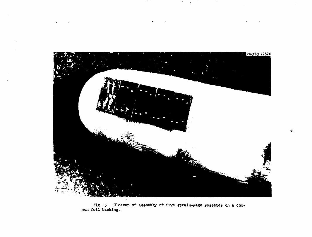
PHOTO 77674
-.0
Fig. 5- Closeup of assembly of five strain-gage rosettes on a common foil backing.

Fig. 6. Model during Instrumentation.
PHOTO 77968
o
£.
V
it
4.V

MMHRB
c o 60 n t, e o
V ^ X
to » to Of 60
<M
o & V a o
CO

PHOTO 78204
Fig. 8. Instrumented model in test frame being subjected to an in-plane moment loading on the nozzle.

13
arrangement acting over the flange on the end of the cylinder. The loading fixtures on the ether end of the cylinder and on the end of the nozzle were attached in a similar manner. Thc^e heavy fixtures in effect constrained the end circles of the shell to remain plane circles. The end fixtures were counterbalanced by weights attached to the cables (Fig. 8).
The external loads were applied by hydraulic rams acting through load cells, and the loads were controlled by the load cell indications. The pressure loading was applied using a hydraulic fluid. To avoid undue straining of the model, weights were used to counterbalance the weight of the pressurizing fluid in the model.
For all 13 loading cases, data were taken in eight steps. In most cases the data were taken at 0. 25, 5C, 75, 100, 100, 50, 0/- of full load. The procedure was then repeated, so that two complete sets of data were taken for each gage every loading.
2.U Data Acquisition and Reduction
The strain-gage data were recorded by a Datum Computer-Controlled Data-Acquisition System. The system consists of a data-acquisition unit composed of a data-acquisition control module controlled by a PDF-S/I computer with the following capabilities: (l) magnetic tape input/output system, (2) in-core calculation ability, and (3) teletypewriter input and output.
The system records the strain data in millivolt readings on magnetic tape. The PDP-8/I computer converts the millivolt reading on the tape intc engineering units (strains in this case) and stores them on a second tape which is compatible with the ORNL IBM 360-9I computer. This second tape is sent to the ORNL 36O-9I computer, and stresses are calculated for each rosette by stripping the "trains off the second tape.
The experimental results presented later in this report and tabulated in the appendix aro generally based on the strain-gage readings at maximum load and on the first of the two sets of data taken from each gage and loading. If the first set of data was questionable for some reason, the second set was used. The strain-gage readings at fractional values of the maximum load were used to check linearity and drift of the gages. In cases

Ik
rfherr nonlinearity or drift was excessive or where an individual gage or circuit was otherwise obviously malfunctioning, the rosette of which the gage was a part was not used in the final results for the specific loading case under consideration. In some instances, a gage that behaved erratically during one loading behaved normally during others. Thus, in the f*-nal plots showing the experimental stresses, results from a given rosette may be included for some loadings but not for others.
Stresses were calculated from the experimental strains by using a modulus of elasticity value of 30 • 10 6 psi and a Poisson ratio of 0.3.
2.5 Variations of Maximum Measured Stresses Around Nozzle-Cylinder Junction
In all cases, the maximum measured stresses occurred at the nozzle-to-cylir.der junction. Consequently, in this section representative experimental results, in the form of maximum measured stress distributions around the nozzle-cylinder junction, are presented and discussed for each loading. Plots of all the experimental point? along each gage line are presented in Chap, k for each loading and compared with theoretical predictions.
To examine the maximum stresses, stress ratios were considered. These ratios were determined by dividing the maximum absolute principal stress value at a point by a nominal membrane stress value. The membrane hoop stress in the cylinder and in the nozzle was used as the nominal stress level for the pressure loading. For the moment loadings on the nozzle or cylinder, the maximum membrane bending stresses (computed by Mc/I) or the membrane shear stress (computed by Tc, J and equal to the maximum normal stress) in the nozzle or cylinder were used as the nominal stresses. For the axial forces on the nozzle and cylinder, the axial membrane stress (calculated by P/A) was used. For the in-plane and out-of -plane forces on the nozzle, the nominal stress was somewhat arbitrarily chosen as the maximum bending stress in the nozzle (calculated by Mc/I) at the level of the top of the cylinder. For the in-plane and out-of-plane forces on the cylinder, the nominal stress was arbitrarily chosen as the utaximum bending stress in the cylinder at its midlength (at the center line of the nozzle).

15
The applied loads used in the experimental analyses are given in Table 1, together vith the r.omi:ial membrane stress levels calculated by the above procedures.
Table 1. A^liec". loads and nominal stress levels
Nominal Loading case Load level membrane stress
(psi)
300 ps i 7,350 l«)0 i n . - l b 5,300 1600 i n . - l b 10,590 400 i n . - l b 5,300 8o lb 10,060 too lb 1,620 60 lb 7,5to 30,000 i n . - l b 990 80,000 i n . - l b 5,300 80,000 i n . - l b 5,300 10,000 lb 1,620 3000 l b 3,880 3000 l b 3,880
The variations in the experimentally determined maximum stresses around the nozzle-cylinder junction are show, in Figs. 9 through 21 for each of the 13 individual loading cases. In each case, the stresses shown were detemined from the strain-gage rosettes immediately adjacent to the Junction, and of the four possible maximum stress distributions - cylinder inside and outside and nozzle inside and outside - those shown produced the largest stresses in each case.
The points labeled "extrapolated maximum" in the figures are estimated maximum stress ratios at the junction obtained by extrapolating the experimentally determined principal stress distributions along each gage line
Internal pressure Out-of-plane accent, M-_ Torsional moment, My_ In-plane moment, M^ In-plane force, F ^ Axial io.ee, F.-„ Out-of-plane force, F„„ Torsional moment, M -Out-of-plane moment, My-In-plane moment, M^ Axial force, F x_ In-plane force, F„ c
Out-of-plane force, ¥

l b
35 EXTRAPOLATED *•'
MAXIMUM •
OH*L - 0*0 73 ^«94
PRESSURE*' MODEL. 4
270' !NTtR\A;_ PRESSURE -•» 90*
— — : J T S O E .>.i%0ER
- • * — : U T S I O E W J L E
Fig. 9. Variation of maximum principal s t ress rat ios aiound the nozzle-cylinder junction for internal pressure.
I 7~
\ 9 180* *
OUNL-OWG 73-2695 ^ — K y
N \ M X N , 1 \ MODEL 4|
s~ 8.5 /EXTRAPOLATED
MAXIMUM
270 0 M*N
90'
OUTSIOE NOZZLE • INSIDE NOZZLE
/ . _ . . . . * y•_.
Fig. 10. Variation, of maximum principal s tress ra t ios around the nozzle-cylinder junction for out-of-plane moment, M^, on nozzle.

My„. o M O O € L 4 5
— ^ C - J T S I O E 3 "<GZZ,_E
;. - - ^ S i D E * W3ZZLE
- 2 7 0 ^ • * —- 90--
\L «f ,.5
EXTRAPOLATED MAXIMUM
O
Fig. 11. Variation of maTiimm principal stress ratios around the nozzle-cylinder junction for torsional moment, My„, on nozzle.
0 * * L - 3 * G TJ-ft$-r
• OOTSIOC , 9 ° * NOZZLE * MODEL 4
— •— >HSiO€ > WZZLt
6' EXTRAPOLATED .
MAXIMUM * " 0 '
Fig. 12. Variation of maximum principal stress ratios around the nozzle-cylinder junction for in-plane moment, M_„, on nozzle.

18
WOOEl 4
• * 90* -
—•—OUTSIOE NOZZLE
— I N S I D E NOZZLE
Fig. 13. Variation of maximum principal stress ratios around the nozzle-cylinder junction for in-plane force, F^., on nozzle.
ORNL-MG 7J-2699
22 / 20
18 16
14 12
— 1 - 2 7 0 # ' r-
21.6 EXTRAPOLATED
MAXIMUM
—•—OUTSIOE NOZZLE — •—INSIDE NOZZLE
~7^ iscr
* -» 0*
MODEL 4
90*»
Fig. 1U. Variation of maximal principal stress ratios around the nozzle-cylinder junction for axial force, F^, on nozzle.

-9
10 8 O
GO
ORNL-DWG 73-2700
r Z N - ! MODEL 4 |
i
/ - - 8.6 / EXTRAPOLATED i MAXIMUM 0
2 7 0 ° - — F Z N - 9 0 ° —
<L
•o— OUTSIDE NOZZLE
-*— INSIDE NOZZLE
Fig. 15- Variation of maximum principal stress ratios around the nozzle-cylinder junction for out-of-plane force, F ? w , on nozzle.
0WM.-DW6 73-2701
O CD MOOES- 4
-27CT- 90' !« O- I
5.0 EXTRAPOLATE0
MAXIMUM
INSIDE CYLINDER
- • — INSIDE NOZZLE
Fig. 16. Variation of maximum principal stress ratios around the noczle-cylinder junction for torsional moment, M x c, on cylinder.
20
ORNL-MG 73-2708 ' J L . — • • i
MOOEL 4
0.5 EXTRAPOLATEO
MAXIMUM
f270*
1 s
1.5
1.0
0.5
*
90*-
— OUTSIDE CYLINDER
- * - INSIDE NOZZLE
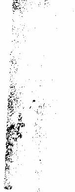
Fig. 17. Variation of aaxlmi principal stress ratios around the nozzle-cylinder junction for out-of-plane noHent, H™, on cylinder.
ORNL-OWG 73-2703
INSIDE CYLINDER
—•—INSIDE NOZZLE
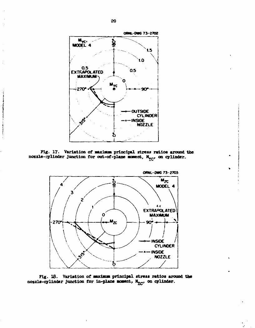
Fig. 18. Variation of mayimw principal rtntt ratios around the nozzle-cylinder junction for in-plane aoaent, M^, on cylinder.

21
270* f-
0Wl»c- OWG 73-2704
6 / " ^ i» \ Fxc N
6 / " ^ ~^-\ MODEL 4 , / / \
^-—*~~^
EXTRAPOLATED MAXIMUM
90*-• r 5 * ^ l
—•— INSIOE CYLINOCR ..*$' —•—INSJOE N0Z7LE
/
Fig. 19. Variation of tmxiam. principal stress ratios around the nozzle-cylinder junction for axial force, F^., on cylinder.
ORNL-QWG 73-2705
- ° — WStOE CVLINOE* " • " INSIDE NOZZLL
Fig. 20. Variation of imrlmm principal stress ratios around the nozzle-cylinder junction for in-plane force, F„c, on cylinder.

22
QRHL-Cm, 7 3 - 2 7 0 6
- INS«e CYLINDER , - !NSI0E NOZZLE /
*
1.3 :EXTRAPOLATED
MAXIMUM
.J
Fig. 21. Variation of maximum principal stress ratios around the nozzle-cylinder junction for out-of-plane force, F_ c, on cylinder.
to the peak stresses at the junction. It should be emphasized that the maxiuum stress estimates are based on a consideration of the stresses along gage lines only; this does not preclude the existence of slightly higher stresses at locations between gage lines. The maximum stress ratios and the locations of the maximum stresses based on both the experimental and the finite-element analyses are tabulated and compared in Chap. 5-
Figures 9 through 21 indicate that, in general, the maximum measured stresses varied in a reasonably smooth and consistent manner around the nozzle-cylinder junction. It i s particularly significant to note that the maximum stress occurred in the longitudinal plane of symmetry only for the internal pressure case, in-plane force and moment, and torsional moment on the nozzle. For al l other loadings, the maximum occurred in the transverse plane of symmetry or at an intermediate position between the two planes of symmetry.
23
3. FEHTE-ELEMHST ANALYSIS
3.1 Background
Thin-shell cylinder-to-cylinder intersection problems have, in recent years, been a favorite with the stress analyst. Their popularity stems not only from the common occurrence of such configurations in practical design, but also from the challenge that they present as complex shell analysis problems. In addition to their use in piping and pressure vessel configurations, thin-shell cylinder-to-cylinder intersections occur in the petroleum industry, which uses tubular structural members extensively in off-shore oil-drilling towers. Much of the cylinder-to-cylinder intersection research, both experimental and theoretical, that has been done was motivated by the off-shore oil-drilling tover application.9
Both analytical and numerical analyses have been developed and applied to thin-shell cylinder-to-cylinder intersection problems. In I96I, Reidel-bach 1 0 developed the first analytical solution for two perpendicularly intersecting cylindrical shells subjected to internal pressure. Eringen 1*" 1 4
and his co-workers corrected seme errors and approximations in Reidelbach's solutions and formulated a solution in which the intersection curve was approximated by a circle. These solutions consisted of products of Krylov functions and Hankel functions of the first kind. A collocation method was used whereby the boundary conditions were satisfied in a least-squares sense at selected boundary points.
In 1969, Hansberry and Jones 1 3 used the method developed by Re*del-bach and Eringen et al. to develop a solution for an in-plane bending moment applied to the nozzle of a nozzle-to-cylinder configuration. In 1970, Maye and Eringen 1 6 developed a solution using Fourier series involving Be&sel functions in place of the Krylov functions. In 1973, Hansberry and Jones 1 7 expanded their solution to include the case of an axial force applied to the nozzle. As in the case of earlier solutions, however, the nozzle diameter was limited relative to the cylinder diameter.
In I967, Bijlaard, Dohrmann. and Wang 1 8 formulated the problem to include the case where the nozzle and cylinder are of equal diameter. They indicated a solution in the form given by Fliigge for closed cylindrical
21.
shells. In 19&9, Fan developed a numerical solution to the differential equations of Flugge and Donoell that i s applicable to the equal-diareter case. He compared his predictions with the experimental results obtained by Riley 0 fur a z»zxle-diameter/cylinder-diameter ratio of l / 2 . By careful choice of some of the factors used in the .solution, he obtained predictions that agreed reasonably well with experiment.
In 1968, Hermann and Campbell20 presented a finite-element shell analysis formulation using flat-plate elements, and as a temple problem they used the l /2 dimeter ratio model tested by Riley. 8 The limited comparisons shown were for internal pressure and indicated reasonably good agreeaent between theory and experiment. In I969, Prince and Rashid 2 1 also presented a flat-plate finite-element shell analysis and used the cylinder-to-cylinder intersection as a sample problem. Their shell analysis program was developed under subcontract to OHRL as a part of the OWL Prestressed Concrete Reactor Vessel Program.
3.2 Finite-Element Method
The finite-element urogram used for the analysis of this model was chosen as being reasonably representative of currently available and widely used finite-element shell formulations. The program was developed at the University of California, Berkeley, under the direction of Professor R. W. Clough. The original program was written for general shell analysis by Johnson 2 2 ' 2 3 and was later modified and adopted by Greste 9 ' 2 4 for treating the "K" joints of cylindrical shells found in off-shore oi l-dril l ing towers.
The basic elements used in the program, shown in Fig. 22, are non-planar quadrilaterals that are built up of an assemblage of four component triangles as shown. Within each component triangle, the in-plane displacements u and v are assumed to vary quadratically over the plane of the t r i angle, except that they are constrained to vary linearly along the one exterior edge. The resulting membrane element, referred to as a constrained linear strain triangle (CLST), has two degrees of freedom (u and v) at each of the five nodes.

ORNL-OWO TO-422*
plSQREJIKP SHE,L,L, V (REPRESENTED BY QUADRILATERAL ELEMENTS)
CONSTRAINED LINEAR STRAIN TRIANGULAR MEMBRANE ELEMENT, u.v ASSUMED TO VARY QUADRATICALLY WITH »,
u»li.».y.» 2.»y.y 2j
v»[i.*,y.ii*,*v.y 2J
07
B i2
QUApRILATERAL ELEMENT T,u (BUILT UP OF FOUR TRIANGULAR ELEMENTS)
HSIEH, CLOUGH, TOCHER PLATE BENDING ELEMENT. w ASSUMEO TO VARY CUBICALLY WITH K,y WITHIN EACH SUB-TRIANGLE
w«[i.»,y.*'.*y.y'.» ,.>'y*.y 5J
> • /
l * . W
y
COVONENT TRIANGULAR ELEMFNT (DIVIDED INTO THREE SUB -TRIANGLES)
Fig. 22. Quadrilateral elemant and component trianglti.
26
The plate bending portion of the component triangle elements has three degrees of freedom at each of the three corner nodes — two rotations about axes in the plane of the element and the transverse, or normal, displace* meet w. The displacement expansion far this element is due to Hsieh, Clough, and Tocher,25 and the element is referred to as the HCT triangle. Full compatibility of displacements and slopes between triangular element boundaries is achieved by dividing the element into three subtriangles and assuming an independent cubic variation for v vithin each subtriangle. One of the tec terms of the general cubic is neglected in each subtriangle, so that in the final assembled component triangle the normal slope varies linearly along each exterior edge. It is this feature that ensures slope compatibility in the resulting element system for plate bending problems. The 27 constants in the three cubic expressions for v vithin the triangular element are reduced to 9 (and related to the 9 nodal degrees of freedom) by internal compatibility considerations. With v varying as a cubic polynomial within each subtriangle, the three components of curvature, and hence the bending and tvisting moments, vary linearly.
The total stiffness (membrane plus bending) of the triangular elements that form the components of the quadrilateral is obtained by superposition of the plate bending element and the membrane element. The membrane plus bending stresses vary piecewise linearly over the surface of the resulting triangular element.
The quadrilateral element stiffness is obtained from that of the four component triangles. In general, due to the curvature of the shell that is being discretized, an arbitrary quadrilateral will be nonplanar. This introduces a complication in the transformation of the triangular element stiffness, because on the element level only two bending rotations per node are defined. When transformed from the element coordinates to some other coordinate system, a third bending tation quantity is introduced, and in the transformed system three rotational degrees of freedom should be considered at each node. This consideration regarding the third rotational degree of freedom also arises in the subsequent assembly of the quadrilateral elements into the total structural stiffness, since adjacent elements are generally not coplanar. In his formulation, Johnson 2 2 chose to retain only tvo rotations per node in the total element assemblage. He argued
27
that since the eleaent plane in a sufficiently fine Mesh lies close to the shell tangent plane at each node, the rotations could he transformed frost the eleaent coordinates (in the plane of the eleaent) to coordinates in the shell tangent plane and the small transformed component of bending rotation about the normal to the shell could be neglected. This is perhaps a reasonable assumption everywhere except at the junction of intersecting shells.
The stiffness formulation for the quadrilateral eleaent, as veil as for the CLST membrane eleaent and the HCT plate bending eleaent, is sua* aarized by Greste.3 The quadrilateral eleaent has five degrees of freedom at each node: u, v, v, and the two rotations. In the final assembled structure, the five degrees of freedom per node are u, v, w, and the two rotations about the shell tangent coordinates at each node.
The task of the finite-element Method is to determine the unknown coefficients of the assumed eleaent displacement functions for u, v, and v. This is done by connecting the quadrilateral elements at discrete points, the corner nodes, and requiring compatibility of displacements and rotations and equilibriua of forces and moments at these nodes. Unfortunately, when the elements are assembled into a curved-shell structure, compatibility and equilibrium are not completely achieved along the element interfaces. Thus there are inherent small errors involved. However, studies by Johnson 2 2 have shown that these errors are not too significant provided a sufficiently fine element mesh is used.
There is an error in intersecting shell problems which is not diminished by mesh refinement. This error arises from the aforementioned neglect of the rotation about the shell normal. At the junction nodes in the cylinder-to-cylinder intersection problem, there are three nonzero rotational components, but only two of these can be retained as nodal degrees of freedom. Greste9 chose to define the tangent plane, and hence the two rotational degrees of freedom, at the junction codes as the cylinder tangent plane. The manner in which he treated the junction nodes thus constrained the normal rotation about the cylindrical shell normal to be zero at the junction. This rotational constraint unreal!stically constrains the bending deformation of the adjacent nozzle elements.

28
This constraint did not greatly affect the analysis of model 1, but its effect was significant in the analysis of model U. A problem arose in the analysis of model h, vith its smal? slender nozzle, that was not encountered in the analysis of model 1 or in similar models with relatively large nozzles. In the cases of the in-plane and out-of -plane forces and moments applied to the end of the nozzle, it was found that the membrane-type axial bending stresses, which should have been constant along the nozzle, vere dissipated vith distance from the end of the nozzle. This dissipation was traced to the neglect of the rotational degree of freedom about normals to the nozzle surface and occurred in model k because of the relatively large deformations of the small slender nozzle. This problem was overcame by redefining the neglected sixth degree of freedom for these loading cases.
The difficulty is illustrated by the example problem shown in Fig. 23, in which the nozzle of model 3 was analyzed by fixing a row of nodes near the junction.2 The mesh shown in Fig. 2k for the nozzle was used, and the nozzle was subjected to a bending moment at the free end. The distribution of normalized bending stress in the outer wall of the nozzle is shown for three different analyses. Also shown is the predicted stress based on simple beam theory vith I = Tra?h and c = a, where a is the radius of the midsurface and h is the nozzle thickness.
The middle curve in Fig. 23 was obtained with the component of bending rotation about normals to the nozzle surface neglected. These neglected rotations are small and are in effect set to zero in the assembled set of equations. Overall equilibrium implicitly requires that small moments be imposed at each node to maintain zero bending rotation. These small constraints combine to counteract a portion of the applied moment and result in the decrease in membrane bending stress depicted in Fig. 23.
To illustrate that these nodal constraints depend on the deflection of the nozzle, the problem was reexamined using a reduced elastic modulus for a section near the fixed end. The nozzle deflection produced by the applied moment was thus increased, and the bending moment was dissipated more rapidly as shown by the left-hand curve in Fig. 23.
The problem was overcome by redefining the neglected degree of freedom in the ncszle.2 Rather than setting the rotations about normals equal

29
DWG 71-3067
in
O
If i-
Fig. 23. Rrample problem demonstrating effects of neglecting the component of bending rotation about normals to the surface of a small slender nozzle.
to zero, the rotations about lines parallel to the nozzle axis were set equal to zero in the final assembled set of equations. The assumption of zero bending rotation about lines parallel to the nozzle axis is a reasonable one and is equivalent to the assumptici, often made in analyzing the local bending in cylindrical shells, that changes in curvature in the hoop direction are negligible compared with those in the axial direction. Bailey and Hicks, 2 e for example, made the latter assumption in examining

30
the effects of a bending moment applied to the nozzle of a nozzle-to-spherical-shell attachment. With this •edification, the Kenbrane bending moment remained constant, as shown by the right-hand curve in Fig. 23. This modification was used in the analysis of the in-plane and out-of-plane forces aud moments on the nozzle.
In conclusion, two significant points should be made. First, even though a computer program, may be checked for some geometries and conditions, there can be other cases for which it does not function properly. Thus, structural analysis programs must be thoroughly validated for the range of parameters over which they are expected tc apply. Second, the problems introduced by considering only five degrees of freedom per node could, be eliminated by retaining six degrees of freedom in the final assembled equations. However, for large systems, the five degrees of freedom per node has a distinct advantage from the standpoint of economy of computer time.
3.3 Finite-Element Idealization of Model
The finite-element representation chosen for model k is depicted in Fig. 2U, which shows developed views of one-half of the nozzle, cylinder, and end plates. It was necessary to consider only one-half of the structure because of symmetry considerations. This mesh layout was developed manually and was arranged so that lines of nodes corresponded to the lines of strain gages in the experimental model. There were 993 nodes, resulting in approximately U500 linear algebraic simultaneous equations to be solved for the unknown displacement parameters. There were 23 nodes along the (half) junction line between the nozzle and cylinder. All 13 loading cases considered experimentally were analyzed using this mesh, and the theoretical predictions were compared with the experimentally determined stresses (Chap. U).
Seven of the 13 loadings - pressure, axial forces on cylinder and nozzle, and in-plane moments and forces on cylinder and nozzle - produce behavior that is theoretically symmetric about the longitudinal plane of symmetry of the model. For these symmetric loadings, it is correct to consider just one-half of the model in the finite-element representation. The

0C-. '-• •.•v.* "A »* : - -» .
k-
V -v
Ic-V \ . - • £ « »~*'f
; ^ « «
Fig. 2k. Finite-element idealization of aodel k.
boundary conditions on nodal displaceaents and rotations are those commonly associated with symmetry conditions.
For the remaining six loadings - out-of-plane moments and forces on cylinder and nozzle and torsional moments on cylinder and nozzle — asymmetric conditions exist, and to consider just one-half of the model in the finite-element representation requires assumptions or approximations in establishing nodal displacement and rotational boundary conditions. Basically, the boundary conditions used were based on the assumption that the projection on the X-Y plane (see Fig. 2) of the boundary remained fixed in

to
the X-Y plane. In other nurds, the displacements in the X and Y directions and the rotation about the Z axis were assumed to be zero for the nodes along the boundary in the X-Y plane. Although these conditions are obviously not strictly correct, they nonetheless seen to be reasonable assumptions that are useful for reducing the size of the problem to be solved.
h. CCMPAMSCB OF THEORY AID EXPERIMENT
The theoretical predictions, based on the finite-element layout shown in Fig. 2k, are compared in this chapter with experimentally determined distributions for all 13 loading cases. For each loading, the theoretical and experimental stress distributions along the five gage lines on the cylinder and nozzle (see Pigs. 3 and k) are presented. The stresses shown are always those parallel (longitudinal) to the gage lines and those perpendicular (transverse) to the gage lines.
4.1 Internal Pressure
The measured and predicted stress distributions determined for an internal pressure of 300 psi applied to the model are shown in Figs. 25 through 29. Figure 25 shows the measured and predicted stress distributions on the outside and inside surfaces of the cylinder and on the outside and inside surfaces of the nozzle along the 0* gage line, which is the longitudinal plane of symmetry (see Figs. 3 and U). The stresses are shown as a function of distance from the junction of nozzle and cylinder midsur-faces. The heavy lines are the predicted stresses, while the fine lines through the experimental points show the measured distributions. The solid lines in each case represent the transverse stresses, which are perpendicular to the gage lines. The dashed lines represent the longitudinal stresses, which are parallel to the gage lines. Thus, we can compare the solid lines with each other and the dashed lines with each other.
The agreement between theory aad experiment is good in Fig. 25, except that the stresses at the junction, which is where the maximal occurs, are at times underestimated somewhat by the finite-element predictions.

33
However, the general shape and distributions of the stresses are well predicted by the theory.
Figures 26 through 29 are arranged to facilitate ready comparison of comparable results. Figure 26 shows the stresses along the 180* gage liue, which is opposite the 0* gage line in the longitudinal plane of ajnmlry. Because of 1 just try, the stresses along the 180* gage line are almost the sane as those along the 0* gage line shown in Fig. 25. Comparison of the two figures shows excellent agreement between results for opposite sides of the nozzle in the longitudinal plane of symmetry.
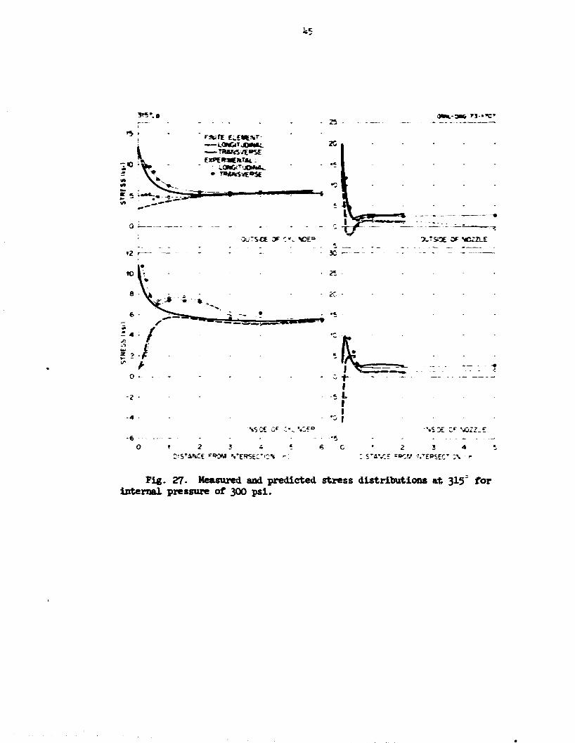
The results for a gage line J»5* from the longitudinal plane of symmetry (see Figs. 3 en* M «re shown in Fig. 27. Figure 27 shows the results for the 315* gage line, which is in the fourth quadrant. Agreement between theory end experiment is not as good here as for the previous two figures. Bote in particular the large disagreement In the shape of the meamiei and predicted stresses on the inner surface of the cylinder.
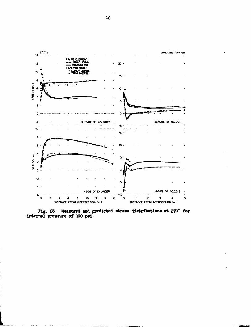
The internal pressure results foe the 270 and 90" gage lines, in the transverse plane of symmetry, are shown in Figs. 28 and 29 respectively. Here the agreement bctwecu theory and experiment is not as good on the transverse plane as along the longitudinal plane; however, since the stresses are low, the disagreement Is perbstps tot too significant. The overall agreement between theory and experiment is generally good.
The method used to determine the estimated maximum experimental stresses and stress ratios was described in Sect. 2.5. The maximnm theoretically predicted stresses were obtained in the same manner; that is, they were taken as the largest absolute values of the principal stresses. To match the experimental maximums, the search for the theoretical maximums was limited to gage lines only.
The maximum experimentally determined stress occurred on the inside surface of the cylinder at lflo", and the m a r l — stress ratio was 3.5. The theoretical maximum stress was on the outer surface of the nozzle at 0*; the maximum stress ratio was 3.1.

U.2 Out-of-Plane Mr— lit loading M^, on •oxxle
The measured and predicted stress distributions for an omt-of-plane moment loading of kOO in.- lb applied t o ttae noxxle of the model are shorn in Figs. 30 through 3k. Results for the f ive gage lines are arranged in the sane manner as for the internal pressure case, although the fourth and second quadrant results are not, in this case, theoretically the sane.
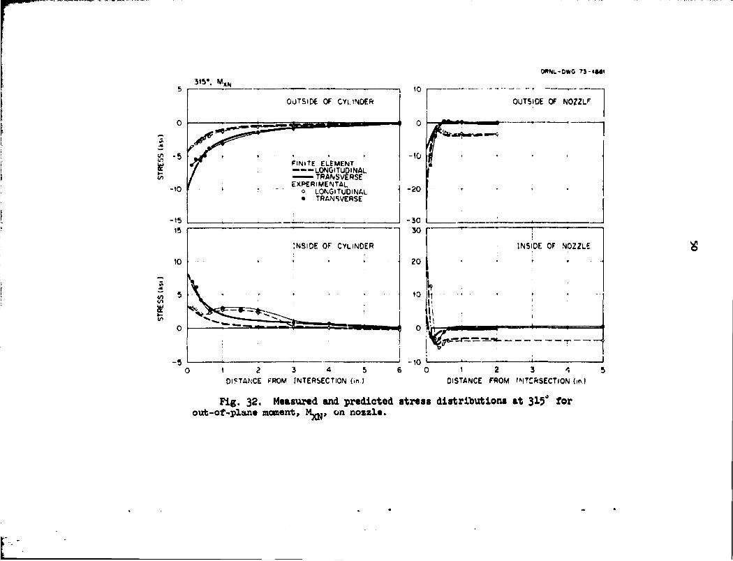
The results in Figs. 30 and 31 are for 0 and Iflo", respectively, in the longitudinal plant of jjaw try. As expected, the stresses are 1—11, since these locations are somewhat analogous to the neutral axis of a bean in bending. The results for the 3I5' gage line, which i s fc5* from the longitudinal plane of symmetry, are shown in Fig. 32. At this location the stresses are larger, and the agreement between theory aad experiment i s very good.
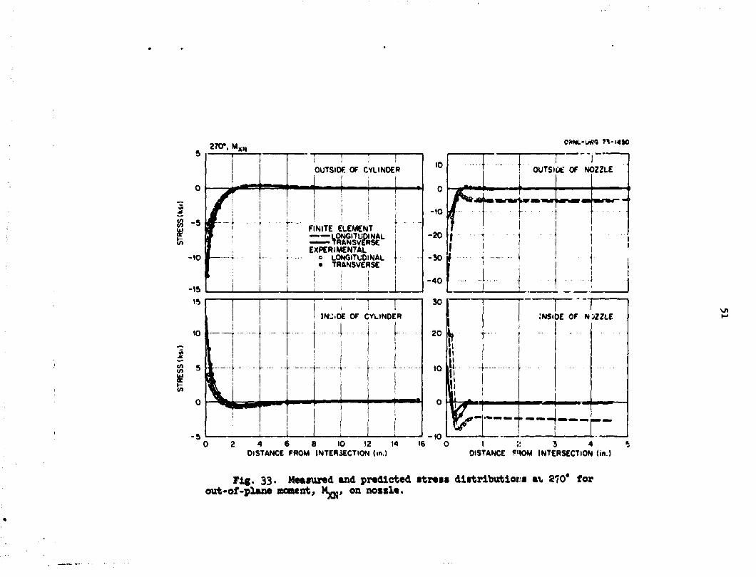
The results for the 270 and 90* r^ge lines, which are located in the transverse plane of syanetry, are shown in Figs. 33 and 34 respectively. Here, the stresses are a T i m on the transverse plane, and the agree-•est between theory and experiment is very good. The mimaii experimental stress i s on the inner surface of the nozzle and is closely predicted by the analysis.
The an Tiro experimentally determined principal stress ratio was 9.5r with the naximua stress occurring on the inner surface of the nozzle at the junction on the 270£ gage l ine. The theoretical maximum was on the outer surface of the nozzle at the Junction on the 270* gage l ine, and the na-riimm stress ratio was 7-6.
V.3 Torsional Moment Loading, M~, on Hozzle
The measured and predicted stress distributions for a torsional moment loading of 1600 in.-ib applied to the nozzle of the model are shown in Figs. 35 through 39. As in the previous case, the fourth and second quadrant results are not theoretically the same. Here the stresses in the longitudinal and transverse planes of symmetry are low and rise to their maximum Levels on the intermediate gage l ine. The distribution of stresses along the interaediate gage line is shown in Fig. 37. which i s 1*5' from
i t
the longitudinal ple-e of syanetry. Here the agreement i s very poor. Ir. general, the stresses are very low, and therefore the distributions show very pror quantitative agreeaent between theory- a-»i »xperiaentxL rcsu.tr.
The "^riF1— experiaentally determined stress ratio was 1.*,, with tt.i —-ri— stress located on the outer surface of the nozzle at tht* Junctisn on the 0* gage l ine. The imtlmw theoretical stress was also on the xrier surface of the nozzle at the sane location. The nazisme theoretical stres: ratio was 1.0.
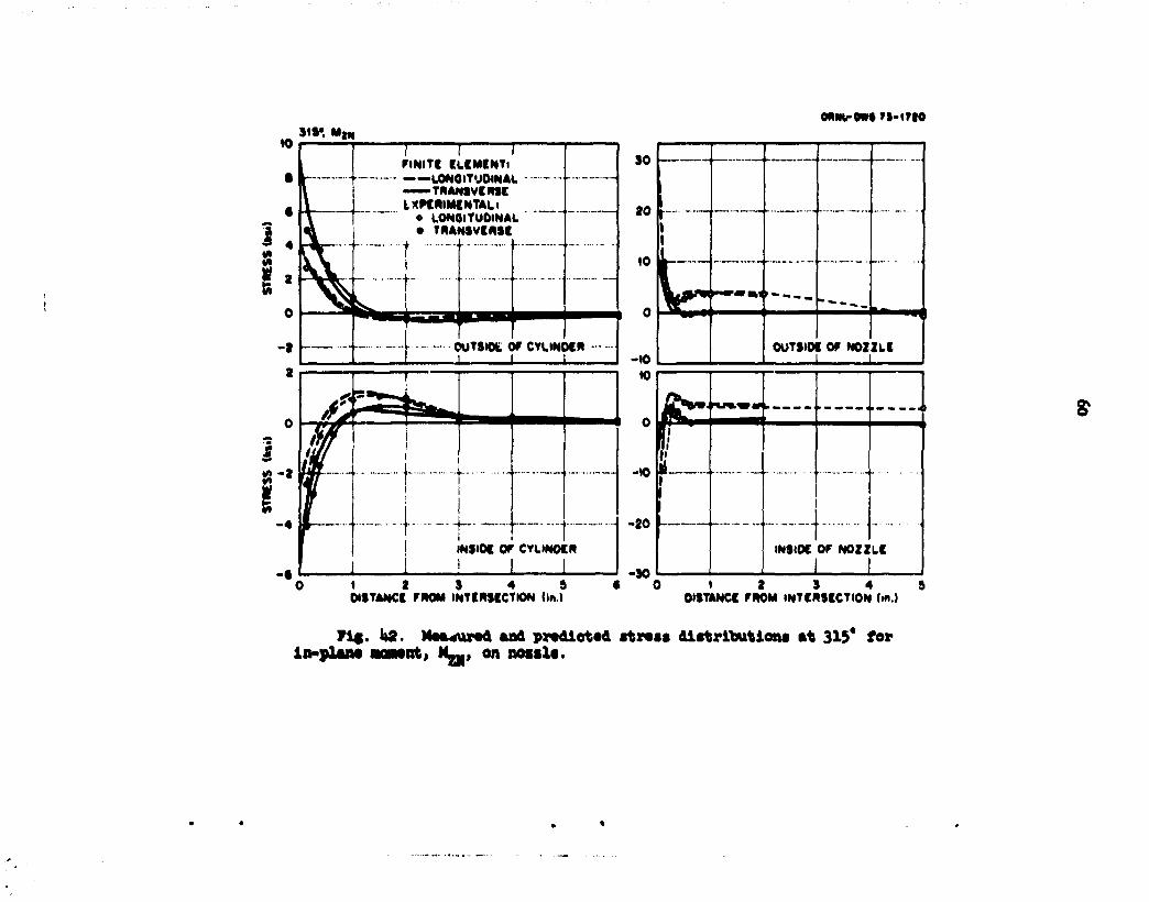
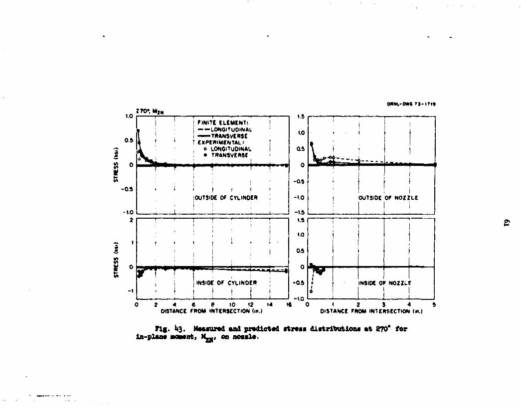
k.k In-Flane Honest Loading. JC-. on Sczzle
The aeasured and predicted stress distributions for an in-plaae z&-nent loading of fcGC in.- lb applied to the nozzle are shown in Figs. - : thro4gh Ui. Here the stresses are large in tht longitudinal place of syr.-aetry. as shown in Figs. '<. and ~1. The agreeaent between theory an-i ex-perieent i s very good for the gage lines in the ioagitudir.il plane of syn-aetry.
The stresses are lower along the gage line l~: frae the lotf it'jrtioal plane of sysawxry; in the transverse plase of sy=r.etry. the stresses %re very low (Figs. 1*3 and *•*). For ttu* loaiirsg. the transverse plane is soaewhet siai lar to the neutral axis of a bean.
The aaxismn experiaentally ieterainei stress ratio was 6 .1 , vi~& the ffafimi stress occurring on the outer surface of the nozzle at the junction along the o' gage line. The saxisue theoretical stress also occurred on the outer surface of the nozzle at the Junction along the 0' gage line. The stress ratio was 7-2.
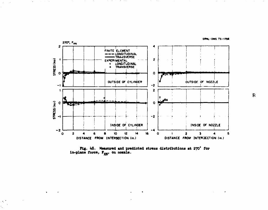
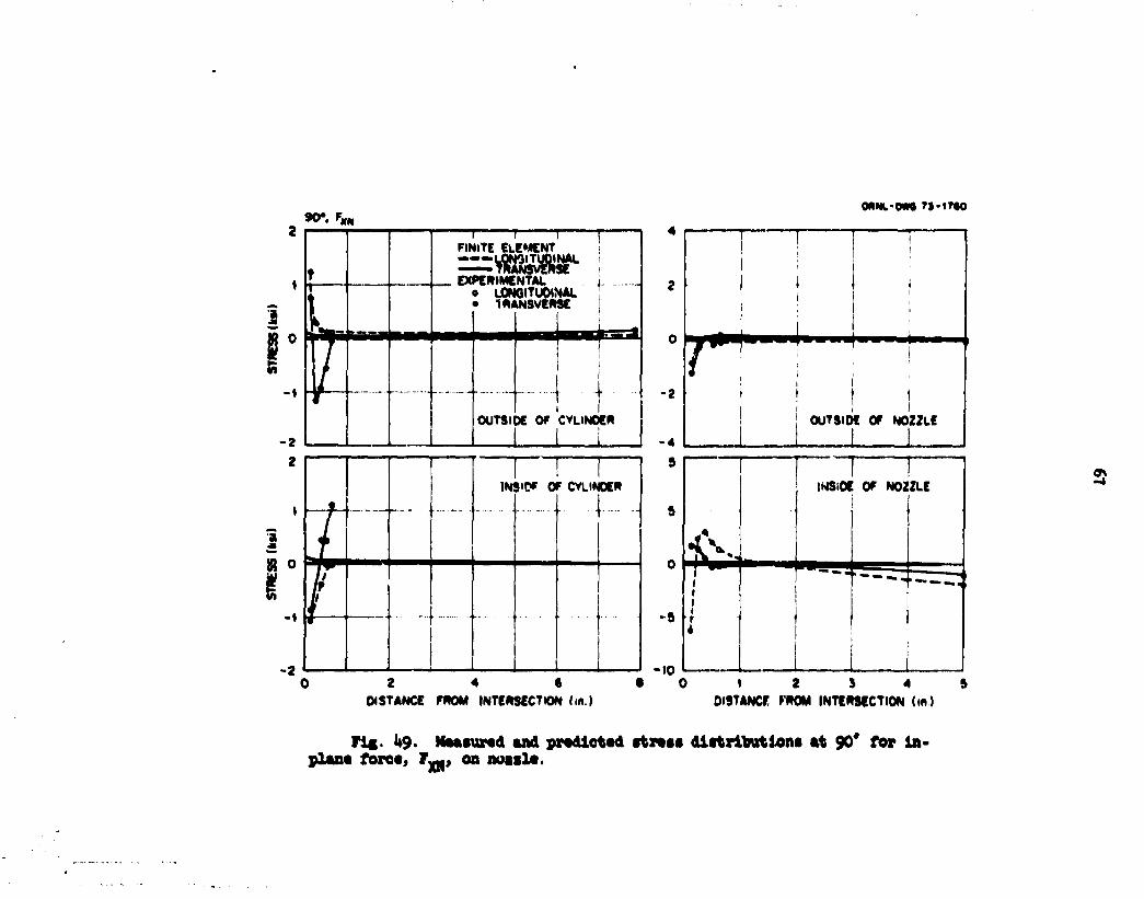
U.5 In-Flaae Force, F-., on Kozzle
The in-plane force applied to the nozzle had a value of So lb. The comparisons of theory and experiaent for the eight gage lines are shown in Figs. *5 through h). The results here are very si&ilar tc the previous case of the in-plane bending aoaent on the nozzle. and the overall agreeaent i s very gc>i.

36
The maximum experimentally determined stress occurred on the inner surface of the nozzle at the junction along the 0* gaps lJne; the ratio vas 7.2. The maximum theoretical stress occurred on the outer surface of the nozzle at the junction along the 0* gage line; the maximum theoretical stress ratio was 8.1.
k.6 Axial Force, F w , on Nozzle
The comparisons of theory and experiment for an axial force of 1*00 lb applied to the nozzle are presented in Figs. 50 through 5k. The agreement between theory and experiment is very good, except for the inside surface of the cylinder on the 315* gage line, which is U5 0 from the longitudinal plane of symmetry. The agreement is very good, particulArly as the larger stress levels are approached on the transverse plane of symmetry (Figs. 53 and 5U).
The experimentally determined maximum stress occurred on the inner surface of the nozzle on the 270° plane at the junction; the ratio was 21.6. The theoretically determined maximum stress occurred on the ouver surface of the nozzle on the 270° gage line at the junction; the ratio was I3.9.
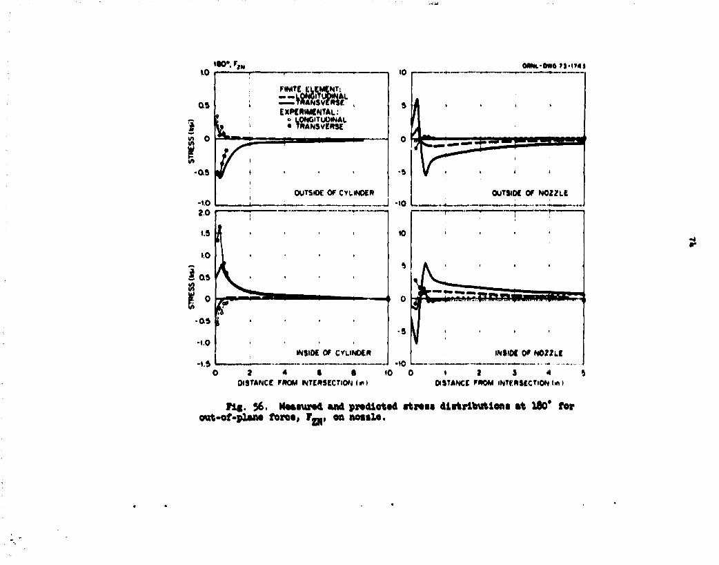
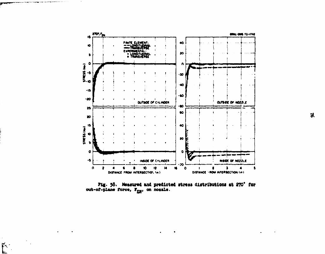
k.7 Out-of-Plane Force, f„„, on Nozzle
The comparisons of theory and experimental data for an out-of-plane force tf 60 lb applied to the noizie are presented in Figs. 55 through 5y. These results are very similar to the care of out-of-plane moment on the nozzle, and the o/eral l agreement between theory and experiment i s again very good, except on the inside surface of the cylinder along the 315' gage line 'Fig. 57). Since the stresses are very small on the 0 and 130 gage lines, the agreement does not look as good as along other gage l ines .
The experimentally determined maximum stress ( ra t io of 8.6) occurred on the inner surface of the nozzle along the 270° gage line at the junction. The theoretically determined maximum stress ( ra t io of 8.5) occurred or. the outer surface at the same location.

37
It. 8 Torsional Moment Loading, My r, on Cylinder
The comparisons of theory and experiment for a torsional moment of 30,000 in.-lb applied to the cylinder are presented in Figs. 60 through 6k.
The experimental stresses are low in the longitudinal and transverse planes o~ syanetry and rise to their maximum levels on the intermediate gage lice. The agreement between theory and experiment is satisfactory on the iintermediate line. However, the maximum theoretical stress is located on the 0" plane on the nozzle.
The experimentally determined maximum stress occurred on the inner surface of the cylinder along the 315° gage line at the junction, and the maximum stress i»axio was 5.0. The theoretically determined maximum stress occurred on the outer surface of the nozzle along the C c gage line at the junction, ard -he maximum stress ratio was 3.1.
U.9 Out-of-Plane Moment Loading, M^-, on Cylinder
The out-of-plane moment loading applied to the cylinder had a value of 80,000 in.-lb. The comparisons of theory and experiment are presented in Figs. 65 through 69. The 0 and 180c gage lines on the longitudinal plane of symmetry are analogous to the neutral axis of a beam in bending, and the stresses are thus low. However, the stresses are not very large anywhere in the model. A peculiarity of the finite-element analysis calculates a large stress at the junction on the 0 and 180C planes of symmetry which is obviously not correct. The maximum stress ratios for this case were the lowest of all 13 loading cases. As a result of the relatively low stress levels, the stress distributions are not too well defined on the 0, 180, and 3150 gage lines, and the agreement between theory and experiment appears to be relatively poor. However, on the gage lines of maximum stress (270 and 90°). the agreement between theory and experiment is fair.
Both the experimentally determined and the theoretical maximum stresses
occurred on the outside surface of the cylinder on the 90° gage line. The experimental maximum stress ratio was 1.3, and the theoretical was 1.0.

38
U.10 In-Plane Moment Loading, M__, on Cylinder
The comparisons of theory and experiment for the in-plane moment load* ing of SO,000 in.-lb applied to the cylinder are presented in Figs. 70 through 7k. The stress levels are a maximum in the transverse plane of symmetry, as shown in Figs. 73 and 7^, and agreement between experimental and analytical results is reasonably good. Where the stress levels are lower along other gage lines, the apparent agreement between theory and experiment is poorer.
The experimentally determined and the theoretical maximum stresses occurred on the inside surface of the cylinder at the junction. The experimental maximum was on the 90° gage line, while the theoretical maximum occurred both on the 90 and 270° gage lines. The maximum experimental stress ratio was 1+.0, and the maximum theoretical ratio was 3.1.
l*.ll Axial Force, F _, on Cylinder
The axial force applied to the cylinder had a value of 10,000 lb. The comparisons of theory and experiment for the five gage lines are presented in Figs. 75 through 79. Considering the relatively low stresses, the agreement between theory and experiment is reasonably good throughout. The agreement between theory and experiment is good for the 270 and 90" gage lines on the nozzle, as shown in Figs. 78 and 79-
The experimentally determined and the theoretically predicted maximum stresses occurred on the inner surface of the cylinder at the junction. The experimental maximum was on the 90* gage line, while the theoretical value was on both the 270 and 90° gage lines. The experimental maximum stress ratio was 3-7; the theoretical stress ratio was 3-0-
U.12 In-Plane Force, F V f >, on Cylinder
The comparisons of theory and experiment for the in-plane force of 3000 lb applied to the cylinder are shown in Figs. 80 through 8U. The agreement between theory and experiment is very good for this loading case.
39
Both the experimentally determined and the theoretical • ^ T W ^ stresses occurred on the inside surface of the cylinder at the junction. The experimental maximum was on the 90 a gage line, while the theoretical maximum was on both the 270 and 90* gage lines. The maximum experimental stress ratio was l».l, and the narimua theoretical ratio was 3.2.
k.13 Out-of-Plane Force, F 7 r, on cylinder
The comparisons of theory and experiment for the out-of-plane force of 3000 lb applied to the cylinder are shown in Figs. 85 through 89. The 0 and 180S gage lines, in the longitudinal plane of symmetry, are analogous to the neutral axis of a beaa, so that the stresses are low along these gage lines. However, the stresses build up for the other gage lines, and the agreement between theory and experiment is very good. A peculiarity of the finite-elarent analysis calculates a large stress at the junction on the 0 and 180" planes of symmetry on the nozzle which is obviously not correct. These points vere neglected.
Both the experimentally determined maximum and the theoretical maximal stresses occurred on the inner surface of the cylinder at the junction along the 315° gage line. The maximum experimental stress ratio was 1.3, while the majdmUB theoretical ratio was 1.2.
5. CONCLUSIONS
Table 2 represents an attempt to concisely summarize the principal findings of this study in terms of maximum principal stress ratios, locations of maximum principal stresses, and the relative overall agreement between theory and experiment for each loading case. The maximum stress ratios are based on the stresses, either measured or predicted, along the five lines of strain gages only and were determined by dividing the maximum absolute principal stress value by a nominal membrane stress value. The maximum experimental principal stresses were determined by extrapolating the experimentally determined stress distributions to peak stresses at the junction in all but one case.

Table 2. Summary of maximum stiffs ratios and maximum stress locations
Loading CMS Experimentally determined
maximum stress* Thooretloal maximum
stress Overall agree-aent between
theory and experlae.it b e Stress ratio Location Stress ratio b 0 Location
Overall agree-aent between
theory and experlae.it
Internal preasure 3-5 Inaide cylinder, 180* 3.1 Outside nossle, 0* Oood, poor M]Q|, out-of-plane
moment on nosale 8.5 Inside nosslo, 270* 7.6 Outside nossle, 270* Excellent
Hftl, torsional mo-<Mnt on nossle
1.5 Outside noaxle, 0* 1.0 Outside nettle, 0* Poor
Mgj,, in-plane moment on nossle
6.1 Outside nossle, 0* 7.2 Outside nossle, 0' Excellent
FJQ,. in-plane fore* on nossle
7.2 Inaide nossle, 0* 8.1 Outside nossle, 0* Excellent
Fy)|< axial fore* on nossle
21.6 Inside nossle, 270* 13.9 Outside nossle, 270* Oood
F-», out-of-plane Tore* on noasle
8.6 Inside nossle, 270* 8.5 Outside nossle, 270* Oood
Mxc> torsional moment on cylinder
5.0 Inside cylinder, 315* 5.1 Outside nossle, 0* Oood
NyC> out-of-plano moment on cylinder
1.3 Outside cylinder,*1 90* 1.0 Outside oylinder, d 90* Pair
N»c> In-plana moment on cylinder
U.O Inside cylinder, 90* 3.1 Inside cylinder, 90' Pair
F x c , axial forte on cylinder
3.7 Inside cylinder, 90* 3.0 Inside oylinder, 90* Oood, poor
Fyo in-plene fore* 01. cylinder
U.:. Inside cylinder, 90' 3.2 Inside oylinder, 90* Exoellent
rZC> otti-of-plam* force 01 cylinder
1-3 Inside oylinder, 315* 1.2 Inside oylinder, 315* Pair
*Baaed on extrapolation of experimental distributions to a maximum at the Junotlon. Ratio of maximum absolute principal atreaa value to nominal atreaa value.
eHaximums all occurred at the junction, "maximum not at Junction, at approximately 90* around on the transverse plane.

The relative overall agreeaent between the finite-eleaent predictions and the experimental results is rated in the table as excellent, good, fair, or poor. These ratings are, of course, a setter of opinion, but an attempt was made to make an unbiased evaluation by basing them on both the overall qualitative agreeaent along the gage lines and on the quantitative agreeaent in areas where the stresses were relatively high. For the internal pressure case and the case of an axial loading on the cylinder, the relative rating is listed as good, poor; that is, the agreeaent was good in regions where the stress levels were relatively high but poor in regions where they were relatively low.
Table 2 indicates that generally the experimentally determined maxi-mnm stress ratios and those based on finite-eleaent predictions are in good agreeaent. Furthermore, the degree of agreeaent between the stress ratios generally correlates well with the relative ratings of the overall agreeaent between theory and experiment. Generally, the agreeaent was best for cases involving loadings on the nozzle. However, the torsional aoaent on the nozzle was an exception; there the agreeaent was poor qualitatively and quantitatively.
In every loading case except one, the maximum stress occurred at tbe junction of the nozzle and cylinder. In the one exception, which was the case of an out-of-plane aoaent, It.-, on the cylinder, the aaxlaaa occurred on the outside surface of the cylinder at approximately 90° around on the transverse plane (around at the side of the cylinder). The stresses on the inside surface of the cylinder were, however, almost as high as those on the outer surface.
In 7 of the 13 cases, the aaximua values occurred in the transverse plane of syaaetry. The torsional moment on the cylinder and the out-of-plane force on the cylinder produced maximal stresses at points intermediate to the two planes of symmetry. The other four cases produced maximal stresses in the longitudinal plane of syaaetry.
Finally, it should be pointed out that, as would be expected, the out-of-plane aoaent and force loadings on the nozzle produced quite similar results, and the in-plane moment and force loadings on the nozzle produced similar results. The stress distributions wer« very similar for each pair, and xhe maximum stress ratios were very close.

U2
In conclusion, the comparison of these particular finite-element predictions with the experimental results shows reasonably good agreement. It is felt that this analysis would be satisfactory for aost engineering purposes.
However, there is room for improvement, particularly in the out-of-plane moment and force loadings on the cylinder. The finite-element analysis for these cases calculated a large stress at the junction on the longitudinal plane of symmetry which obviously is not correct. The inclusion of the sixth degree of freedom, at least in the junction region, might improve the predictions.
ACKHOWLEDCMHfTS
The planning and execution of the analytical and experimental study reported here would not have been possible without the assistance and cooperation of many individuals, both within OHWL and outside. The authors are deeply indebted to these people for their contributions.
Special thanks are due J. P. Rudd for the instrumentation of the model, which was a very painstaking task. The finite-element computer program used in the analysis was developed at the University of California, Berkeley, by C. P. Johnson under the direction of Professor R. W. dough.

o«*~-:*6 -*-«^o*
x v ^ i ; -
C^TSDE > C».<S3e s x*soe -y NOZZLE
0 2 4 6 8 D!S'A»lCE *%DW ftT£PS£C* Z".
Fig. 23. Measured and predicted stress distributions at 0° for internal pressure of 300 psi.

uu
«80*.p IMG T 5 - t n »
F««TE ELEMENT; LONGlTUOlNAL TRANSVERSE
EXPERIMENTAL: o LONGtTUCMNAL • TRANSVERSE
OUTSIDE OF CYLINDER
25
OUTSIDE OF NOZZLE
2 4 6 8 10 DISTANCE FROM INTERSECTION U«J
2 3 4 DISTANCE FROM INTERSECTION ( « )
Fig internal
. 26. Measured and predicted stress distributions at 180° for pressure of 300 psi.
i *
3*5*. p
- C • TRCIKSVE*SE
0 ;
»2 o 'sct y c v£=
rj-.»c»
x*soe o* ,*irzLE
?w NSD€ C c • w £ °
- 1 -1
-5 l 1 1
' - I
2 3 4 c 6 C s rANCE c»0M r ;
2 3 4
Fig. 27- Measured and predicted stress distributions at 315" for internal pressure of 300 psi.
i6
- » n t Ei£*C»T
'HStOE OF C»i.<NOC»» •• <*SiOE OF NO/Zi-E
2 « 6 8 < O ! ? < 4 « 6 0 ' 2 3 4 O'S'ANCE c » o v >VE«»S£CT>0* •'•" "> CXSTANCE "»OM fcTEWSECTiON :« i
Fig. 28. Measured and predicted stress distributions at 270* for internal pressure of 300 psi.

*7
«r.» *S--»C
~ LflNGiTuDMkL
> jjON&ruOMMi.
-2 OUTSIOC of c»L*ce«»
20
>C •»
• ^ ^ - ^
OUT&CCO* NOZZLE
25 -
2C •
^ •
fc= •%SiO€ C* :»L' ' iO£» 1 • « « 0* "JOKLE
2 3 t ; (, e -•o - - 2 3 4 yS'AHCt ct*CV 'NTE«»S£C*:0»i -T : G<S'4*C£ r » o » Hf»E*sec T 'Ca •»
Fig. 29. Measured and predicted stress distributions at 90° for internal pressure of 300 psi.

0*. M K N
4" —! 1 T" FINITE ELEMENT
EXPERIMENTAL
I ttT«L
OUTSIDE OF CYLINDER
2 4 6 8 DISTANCE FROM INTERSECTION (m.)
'" •
! INSIDE OF CYLIN DtR
ygw.
t
t
1 I
10
oftNi-t>wa ri-wr
&
DISTANCE FROM INTERSECTION (.«,»
Fit. 30. MMtuMd tnd prtdlettd it m i distributions tt 0* for out-of-plant aoMnt, M^, on noitlo.

i.O
T*%
8 r
i -
FINITE ELEVE*T: ——Um6tVJO0tH .
TRANSVERSE EXPERIMENTAL
o - O N S I T U P * * ^ • TRANSVERSE
9" -L 2 f
' »
- t
j f ~ ^ 2 * 3
OUTSOE OF CYLINDER
INSiOE OF CV- NDER
2 4 6 6 OlSTANCE FROM INTERSECTION <•«.:
- - 4 1 "f € "
K)
OUTAGE OF NOZZLE
It&X OF \CZZ-t
» 2 3 4 3'STA\CE C »CV INTERSECT.QM {.P.!
WAJ. 31. Hwnu*d and predicted stress distributions ct 180" for out-of-plane •oment, M_j, on nozzle.
0*NL-D*G 73-«Ml 31V. W X N
in
-10
10
CO
OUTSIDE OF CYLINDER
— • I
FINITE ELEMENT LONGITUDINAL TRANSVERSE
EXPERIMENTAL o LONGITUDINAL • TRANSVERSE
INSIDE OF CYLINDER
- 5 1 2 3 4 5
DISTANCE FROM INTERSECTION (in ) 1 2 3 ', 5
DISTANCE FROM INTERSECTION <m.)
Fig. 32. Measured and predicted stress distributions at 315" for out-of-plane moment, M™, on nozzle.
8
270*. M X N
OftNl-utfQ 7VHJ0
I
• -
2 4 6 8 10 12 14 DISTANCE FROM INTERSECTION (in.)
i ;: 3 4 * DISTANCE ?'*0M INTERSECTION (in.)
\j\
Fig. 33. Measured and predicted stress distribution ax 870* for out-of-plane moment, VL^, on nossle.

15
10
90*. M X N
ONNL-OWO r s - t t m
! 1 1 FINITE ELEMENT — — LONGITUDINAL
1 1 , — T R A N S V E R S E H
EXPERIMENTAL o LONGITUDINAL
-— • TRANSVERSE
—
• j = 1
I OUTSIDE OF CYLINDER . . ,L, .1 L
-10
•15
*A
i - • - i >
.. ...... ... —-
r-^~ INSIDE OF CYLINDER
1 ! L, ._ . . . -
40
50
20
10
0
-10 10
r: I 1
— - — -
__ r: I 1
— - — -
i < • — w_ _ — . . _ < • —
• « • w_
OUTSIDE OF NOZZLE .... , - J J
1 2 3 4 5 6 7 8 DISTANCE FROM INTERSECTION (in.)
- 30 0 1 2 3 4 5
DISTANCE FROM INTERSECTION d.t.)
Fig. 3k. Measured and predicted street distributions at 90* for out-of-plane aonent, Mj_, on nossle.

0 * . M V N WNL-OWO rs-trtt
FINITE ELEMENT: --LONGITUOINAL —— TRANSVERSE EXPERIMENTAL: :wamt
2 4 6 e K> DISTANCE FROM INTERSECTION («.)
1 2 3 4 OISTANCE FROM INTERSECTION (in.)
Fig. 35 • ItaMurtd and prodlotsd stress distributions at 0* for torsional sHswat, M^g, on nossls.
vn

W . M ™ ORW.-OWO T3-»T1J
FINITE ELEMENT: — —LQNClTUQlNAL -—TRANSVERSE EXPERIMENTAL:
• LONGITUDINAL • TRAN1
•0 r
•S
-«0 10
jPoo
—' 0 te -10 X
2 4 6 6 DISTANCE FROM INTERSECTION (in.)
ftnfZ?7fr^«^MrrJt"" j »
OUTSIDE OF NOZZLE I I
INSIOE OF NOZZLE J 1 1
1 2 3 4 DISTANCE FROM INTERSECTION (in >
Fig. 36. Maaaurad and pradlotad atrau distributions at 180* for torflonal aoannt, M™, on nossl*.

3I5* My,, ORW.-DWO TJ-1T1S
3 4 9 FROM INTERSECTION (in.)
1 2 3 4 OISTANCE F.TOM INTERSECTION (m.)
Fig. 37. Maaturad and pradlotad atraaa distribution* at 31?* for torsional aomot, H^, on nossla.
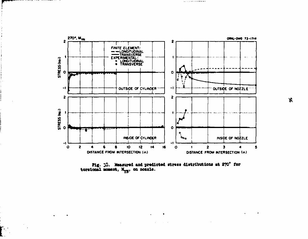
2 7 0 - , M w OmiL'Om 73-1714
0
FINITE ELEMENT; — —LONGITUDINAL —TRANSVERSE EXPERIMENTAL:
o LONGITUDINAL • TRANSVERSE
M H I
OUTSIDE OF CYLINDER
' •
l\»
f ,
0 /
1 * J 0
0
INSIDE OF CYLINDER 1 1 1 -1 1
INSIDE OF NOZZLE 1
8 10 12 14 16 DISTANCE FROM INTERSECTION (in.)
1 2 3 4 DISTANCE FROM INTERSECTION (in.)
Fig. 30. Maaaurad and pradictad itr«ii distributions at 270* for torsional Noaant, Hyj,, on nostl*.

•O". My H 4 OR*.-MM Tl'ITia
i i
- 4 -l
1
FINITE ELEMENT: --WQNWTUOINAL —TRANSVERSE EXPERIMENTAL!
: MBHRSt!t 2
9 4 »
*
' < • • - •
A t i 0 f ^ ^ " ^ ^ " " ^ IT" «l 0 v\
! i OUTSIDE Of CVLINI )ER
•2 OUTS0E Of NOZZLE
i l )ER
I 1 4
2
^ _
. . . .
} 0
I • •- - • i • -2 • f • - •
4 . . .,
i 1 WStOC Of CYLINDER _4 1 I •4
INSIDE Of NOZZLE
I 2 3 4 S » 7 DISTANCE FROM INTERSECTION (in.)
1 2 S 4 DISTANCE fROM INTERSECTION(in)
Fig. 39. Maaaurad and pradlotad itrtss dlatrltatlOM at 90* for torsional aoMnt, Hy-, on nossla.

OftNirDwors-m* 0-. M l M
OUTSIOC OF NOZZLE
•-•i— t 1 Bo-
i .....
— tNStDE OF NOZZLE - -
O 2 4 6 8 10 OISTANCE FROM INTERSECTION (in.)
0 1 2 3 4 5 OISTANCE FrtOM INTERSECTION (in.)
Fig. kO. Measured and predicted stress distributions at 0* for in-plans acsMot* M_|, on nossle.
o»

ORNL-0W9 7J-171« •JO*. M Z N
0 2 4 6 S DISTANCE OP INTERSECTION On.)
1 2 3 4 5 DISTANCE FROM INTERSECTION (in.)
Fig. Ul. Maaaurad and pradlotad ftrati distributions at X80* for ln-plana aoaant, H^, on noatla.
OftNtrM* U-1TIO
10
•
4
2
0
SIS*. M , N
! 1 ! PINITI ElEMENTi ——LOHOlTyOlHAL
I -—TRANSVERSE L IXREAIMENTAU \ J o LONQlTUOtNAL « • TRANSVERSE
_ OUTSIOL OF CTUNDER •-1 1 i
50 , ._.
20
10
r i i
\ f~ r
0
-10 OUTSIDE OP NOZZLE
1 I 10
1 2 5 4 9 DISTANCE PROM INTERSECTION (in.)
0 1 2 5 4 5 DISTANCE PROM INTERSECTION (in.)
Flf. U2. MMuurod and predicted stress distributions »t 315* for in-plAM MMnt, Hgi on nosslt.
OUNl-DWO M-t7«»
1.0 | 1
0 T * » > *
1 r
f •
rr-r
| FINITE ELEMENT) I — — LONOlTuOlNAL
TRANSVERSE XPERIMENTAL: ' o LONGITUDINAL i
TRANSVERSE
m +-H-t r \
lOUTSIDE OF CYLINDER
mamcssr. • ^ " " J " • j * n i * ' , * |
INSIDE OF CYLINDER t t f
2 4 6 P 10 12 14 16 DISTANCE FROM INTERSECTION (in.)
-1.5 1.5
1.0
0.5
0
-0.5
•10
yr\ 1 INSIDE OF NOZZL! t
6 , ,
0 1 2 3 4 5 DISTANCE FROM INTERSECTION (m.t
f*
Fig. U3. Maaaurad and pradictad ft ran distribution* at 870* for in-plana mcmnt, M^, on noaala.

QftNt-owon-im to
as
W . M , M
-as
-1.0
to
as
y FINITE ELEMENT) — —LONGITUDINAL — TRANSVERSE EXPERIMENTAL* o LONGITUDINAL • TRANSVERSE
fS^ffffffli^TS
OUTSIDE OF CYLINDER
-as
• M H « « W !
2
1
0
-1
-2
2
1
0
-1
-2
OUTSIDE OF NOZZLE
1 !
INSIDE OF CYLINDER
M—I—t-1 .,
i -j
1 2 3 4 S 6 7 DISTANCE FROM INTERSECTION (m.)
0 1 2 3 4 1 DISTANCE FROM INTERSECTION (in.)
Fig. Uk. Maasurad and pradlotad atraas diatributlona at 90* for in-piano MMntj M^, on nosila.

OMN.-OWO 7J-I7M
K) I r
8
8
—i 1 r OUTSIDE OF CYLINDER
FINITE ELEMENT LONGITUDINAL TRANSVERSE
EXPERIMENTAL o LONGITUDINAL • TRANSVERSE
20
"IF -40 fj
- 6 0
- 8 0
-100
1 1 1 4 - OUTSIDE OF NOZZLE
• + — 4 . — 4 - — 4 —
INSIDE OF NOZZLE
2 4 6 8 OISTANCE FROM INTERSECTION (in.)
- 2 0
10 0
^ S - ' - ~ - . - - ' •• 2 3 4 5
DISTANCE FROM INTERSECTION 'in.)
OS
Fig. U|5. Measured and predicted stress distributions at 0* for in-plane force, i'm, on nossle.

«•. s„ MM.-MM TS-1TM
8
I
• • ! 1 - INSIDE OF NOZZLE
fi « * _ • ^ w s - j ^.*=.—' — — — — = ? . T * » I
F --1 - —
—
0 2 4 6 8 DISTANCE FROM INTERSECTION (in.)
0 I 2 3 4 S DISTANCE FROM INTERSECTION (in.)
Fig. It6. Measured and predicted street distribution! at 180* for in-plane fore*, Fy-, on nossle.

31S«. F K M
OftNt-DWO 7J-1T97
OUTSIDE OF CYLINDER
FINITE ELEMENT ——LONGITUDINAL
TRANSVERSE EXPERIMENTAL
o LONGITUDINAL • TRANSVERSE
INSIDE OF CYLINDER
1 2 3 4 5 DISTANCE FROM INTERSECTION (in.)
20
0
-20
-40
-60
-80
-100 60
40
20 I
H—[• OUTSIDE OF NOZZLE
— i — r ~ INSIDE OF NO/ZLE
" °W^ -20 J_
0 1 2 3 4 5 DISTANCE FROM INTERSECTION (in.)
ON \J1
Fig. V?• Measured and predicted stress distributions at 315* for 1'i-plane force, Fy-, on nossle.
ORNL-OWG 73-ITS* 270*. FnH
m+
FINITE ELEMENT — LONGITUDINAL
TRANSVERSE EXPERIMENTAL
o LONGITUDINAL • TRANSVERSE
HH-! I i ; : ' INS IDE OF CYLINDER
-2 2
TTT / OUTSIDE OF NOZZLE
0 •
•2
jrffi.
!' ' ' ! '
; INSIDE OF NOZZLE J ; I
2 4 6 8 10 12 14 16 OISTANCE FROM INTERSECTION (In.)
0 1 2 3 4 5 DISTANCE FROV INTERSECTION (in.)
Fig. U8. Measured and predicted strata dlrfcrifcutiona at 270* for in-plane force, F^,, on notslo.
90*. F, OftNl-OWO T>.1T«0
XH
-1
?
i r i
FINITE ELEMENT
EXPERIMENTAL 1 » LONGITUDINAL • 1RANSVERSE j
i
p OUTSIDE OF
1
I i
CYLINDER
i Jr
OUTSIDE OF
1
I i
CYLINDER
i
-1
- 2
J *
/
IN J'DF a • • - — ' • •
r CYLIN
-
OEM
/ ' • • - • • - .
2 4 6 OISTANCE FROM INTERSECTION (in.)
F V M ^ O T W
OUTSIDE OF NOZZLE
1 i—r INSIDE OF NOZZLE
0 1 2 3 4 DISTANCE FROM INTERSECTION (in)
Fig. U9. MMturad and predicted «tr*si distributions at 90* for in-plana forc«, FJQJ, on nossl*.

V)
Si
MM TJ-»?I»
5 °
E -a
•«o
4
; i i ! ! i
4
1 !
f !
r i i INSIDE OF CYLINDER
I I 2 4 6 8
DISTANCE FROM INTERSECTION (•*>.)
20 10 0 1 2 3 4
DISTANCE FROM INTERSECTION (in)
s
Fig. ?0. Measured and predicted street distributions at 0* for axial force, Fyjj, on noaale.

t * * F , ORNL-OWO T|-|T>|N
| i/> i/t
w»
I l/t
2 4 « S OISTANCE PROM INTERSECTION (MI)
( 2 3 4 OISTANCE FROM INTERSECTION (in.)
Fit. 51. Mtaiurtd *nd pr«diot«d itrtsa distribution! at 180* for •xlal force, Fy,., on nosslc.

i
319», F w ORNL-OWO 7»-(7M
30
20
10
OUTSIDE OF CYLINDER J 1 1 -10
10
f
OUTSIDE OF NOZZLE J_
i
K fe-2
-4
-6
I 1 i
r' — — — •
^ t m m m m ^ r' — — — •
^ t m m m m ^ M ^ ^ ^ M M - J
f r°> r = . - © - - - i r ^ ^
t m m m m ^
f r°> r = . - © - - - i
i
INSIDE OF CYLINDER 1 i
i
INSIDE OF CYLINDER 1 i
I •(0
INSIDE OF NOZZLE -20
1 2 3 4 5 DISTANCE FROM INTERSECTION (in.)
1 2 3 4 DISTANCE FROM INTERSECTION (in.)
Fig. 92. Haaaurad and pradlotad rtrass distribution* at 3X9* for axial forea, F~, on noisla.

2 T 0 « F W
FINITE ELEMENT:
EXPERIMENTAL:
2»
20
IS
10
ft
0
to
QRNi-PWO 7>-tTM
—r <~ i
1 t i
i t
i i | t L • ' < (
-Xi '"[ 1 OUTStOE OF NOZZLE
y^< T"*" iTi n "Tp
-10 J
•20
2 4 6 8 tO 12 14 16 DISTANCE FROM INTERSECTION (*>)
I
INStOE OF NOZZLE
2 3 4 DISTANCE FROM INTERSECTION (in.)
Fig. 53. Mt«tur«d tnd prtdicttd rtrui distribution! at 270* for axial fore*, F™, on nossla.

90", F. OMNL-OWG rj-1711
2 3 4 5 6 7 DISTANCE FROM" INTERSECTION <w».)
1 2 3 4 DISTANCE FROM INTERSECTION ( « )
Fig. 5k. Measured and predicted stress distributions at 90* for axial force, Fyj., on noszle.

O'.F. IN
—TRANSVERSE EXPERIMENTAL;
e LONGITUDINAL • TRANSVERSE
OUTSIDE OF CYLINDER
INSIOt OT' CYLINOER
2 4 ft a DISTANCE FROM INTERSECTION U.)
1 2 3 4 OISTANCE FROM INTERSECTION <* )
Pig. 55. Maaaurad and pradiotad atraaa distribution* at 0* for oufc-of-plana foroa, F M , on noaala.
iao». r. to IN
FINITE ELEMENT:
EXPERIMENTAL:
•0 ONNi-DtMM-lMl
2 4 ft a DISTANCE FROM WTEWECTlON I * )
I 2 S 4 DISTANCE MOM INTERSECTION <* I
rig. 56. Maaaurad and pradlotad strati distribution* at I80* for out-of-plana fore*, T^, on noasla.

10 »»*.yw 0MW.-0W0 M-<M)
riNtTE CCCMtNT:
EXPCAlMENTAl:
« 2 S 4 S DISTANCE FROM INTERSECTION (m)
. * . - . „ - . . ««*<. .« i
OUTSIW C# N O t t t *
INSH* W N0Z2U
( 2 3 4 DISTANCE FROM INTERSECTION (m )
Fi§. 57• Mooeurad and pradiotod atraaa diatributionc at 315* for out-of-plana foroa, F^, on noaala.
»»«I»4I
J
riMTC ClCMCNT; -smmt i CMMMMfNTAt:
OUTSOC or en.t*oi* 1 . r
f T
• *
i i i * * »
-•0 •0
40
ao
CUTMK or Noin.e i.i i , nt — — a —
" • " T — t
r — •
"i - i <
i V 1
i
1
ft II
• t
fc 2 4 ft • 10 I t 14
OtSttNCC fHOM iNTCDKCTlOr. '*»>
•20 WHO* Or NOZZlC
. > i
1 1 4 0 I DlSTMCC -MOM WTCMICTHJN li«i)
rif, 58. MoMurtd and prtdlcttd ftrtis dtlitrlbutioni at 270* for out-of-pl*n« force, Fm., on nosslo.

25
20
90*. K„
-_- 15
t «
$ 10 • -
"» 5
1
V* "
0 0
• 4 m i _
FINITE ELEMENT; =IV«5N»E L
EXPERIMENTAL: o LONGITUDINAL • TRANSVERSE
m mHirr-T— y
OUTSIOE OF CVLINOf R
INSIDE OF CYLINDER
t 2 3 4 * 6 7 DISTANCE FROM INTERSECTION tin)
ORNL-OWG TJ-IT44 T
= t = * OUTSOE OF NOZZLE
! T £
1
INSIDE OF NOZZLE
1 2 3 4 DISTANCE FROM INTERSECTION («»
Pig. 59- Maaaurad and predicted atrata diatributiona at 90* for out-of-plant forco, T7H, on nozzle.
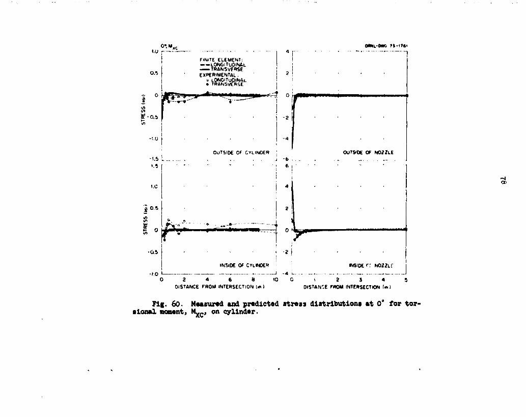
ONNL-OWO ?S-I7»i
-..6 L_ »5
t.C
i M !
FINITE ELEMENT. — -LONGITUDINAL — TRANSVERSE EXPERIMENTAL :
o LONGITUDINAL • TRANSVERSE
'f* -as
rl
OUTSIDE OF CYLINDER \ . . . . .j - 6
I d
- » • . .
••»-- d - 2 t
"1
OUTSIDE OF NOZZLE
I INSIDE OF CYLINDER | INSIDE r r NOZZLf
0 8 4 6 tt 10 C ^ 2 3 4 5 OISTANCE FROM INTERSECTION («.) DISTANCE FROM INTERSECTION (in)
Fig. 60. Measured and predicted stress distributions at 0° for torsional moment, M ^ , on cylinder.

1.0 180", M x c ORNL-0W0 73-1765
2 0 . 5 </>
»-to o ^ _
-Q5 ' 1.0
0.5
to 0 UJ
</>
-0.5
-1.0
FINITE ELEMENT: LONGITUDINAL TRANSVERSE
EXPERIMENTAL: o LONGITUDINAL • TRANSVERSE
OUTSIDE OF CYLINDER
INSIDE OF CYLINDER
0 2 4 € € DISTANCE FROM INTERSECTION (iru
1 2 3 4 5 DISTANCE FROM INTERSECTION (in.)
vo
FI,T. 61. Measured and predicted stress distributions at 180° for torsional moment, Mj.-, on cylinder.

31V. M w
FINITE ELEMENT: ——LONCITUOINAL — TRANSVERSE EXPERIMENTAL:
o LONOlTuOlNAL • TRANSVERSE
4
3
2
1
0
-1
-2
-3
(A
ORftfOftl M-17»»
: ' ! ! 1 i
1 ; • ! • •
...
N4- • T ! ' . . . *<
! ; 1 ! OUTSIDE OF NOZZLE
1 : , I 1 i
•
1'
1 i i
- "-— , - —'
. . .
^ i
I
T • -
1 1 i ....
INSIDE OF NOZZLE i 1
8
1 2 3 4 5 DISTANCE FROM INTERSECTION On.)
0 1 2 3 4 DISTANCE FROM INTERSECTION (in)
Fig. 62. Measured and predicted stress distributions at 315* for torsional moment, M ^ , on cylinder.
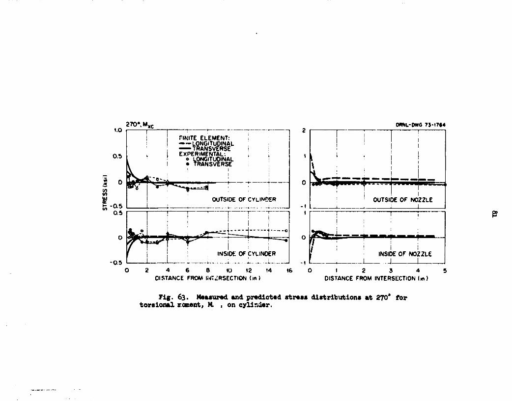
«.o 270' , M x c
0.5
°SH^
FINITE ELEMENT: — — LONGITUDINAL
TRANSVERSE EXPERIMENTAL:
• o LONGITUDINAL I • TRANSVERSE
* «S-*l T
OOTSIDE OF CYLINDER
— J-=f
0.5 INSIDE OF CYLINDER
2 4 6 8 10 12 14 16 DISTANCE FROM INTERSECTION (in)
OftNL-DWG 75-1764 T
> i i : ! i
OUTSIDE OF NOZZLE
INSIDE OF NOZZLE . . .J 1
2 3 4 DISTANCE FROM INTERSECTION (in)
Fig. 63. Measured and predicted stress distributions at 270* for torsional roment, M. , on cylinder.

• 0 9 0 * M), c ORNi.-OWG 7S-1763
0.5
FINITE ELEMCN T: — — I.UNGITU0INAL —— TRANSVERSE EXPERIMCNTAL:
o LONGITUDINAL • TRANSVERSE
• 2 3 4 5 6 7 OlSTANCE FROM INTERSECTION (in.)
INSIDE OF NOZZLE 2 L- - - - — - -
8 0 1 2 3 4 5 OlSTANCE FROM INTERSECTION (in.)
Fig. 6k. Measured and predicted stress distributions at 90° for torsional moment, My-, on cylinder.

0* .M Y C
OWK.-DW0 n-ITM
— I 1 FINITE ELEMENT ——LONGITUDINAL —TRANSVERSE EXPfRIMENTAL
o LONGITUDINAL • TRANSVERSE
8
8 ft
40
30
20
•0
•4-
1 i
N M f •+ r-
2 4 6 8 tO DISTANCE FROM INTERSECTION Itn.)
OUTSIDE OF NOZZLE
INSIDE OF NOZZLE
0 I 2 3 4 S DISTANCE FROM INTERSECTION <m.)
00
Fig. 65. Measured and predicted stress distributions at 0* for out' of-plane moment, M ^ , on cylinder.
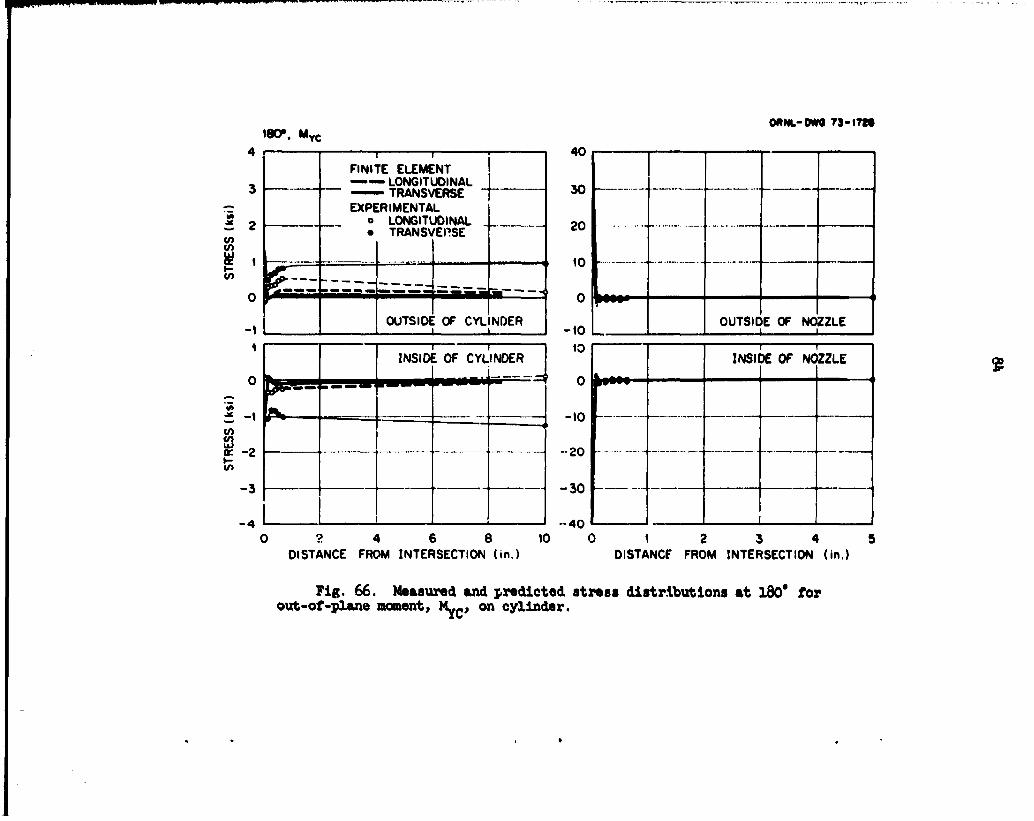
180\ M Y C
ORM.-0W0 79-t7te
4
3
2
1
0
-1 1
0
-1
-2
- 3
1 1 FINITE ELEMENT - — — LONGITUDINAL — TRANSVERSE EXPERIMENTAL
o LONGITUDINAL • TRANSVEPSE
^ ^ SwSi
OUTSIDE OF CYLINDER l I
30
Oft
30
Oft
10
0
10
10
0
10
10
0
10 OUTSIDE OF NOZZLE I I
t 1 1
INSIDE OF CYLINDER
M M Hi ^
10
0
-10
-20
- 3 0
•40
1 1 INSIDE OF NOZZLE
0 ? 4 6 8 10 DISTANCE FROM INTERSECTION (in.)
0 1 2 3 4 5 DISTANCF FROM INTERSECTION (in.)
Fig. 66. Measured and predicted stress distributions at 180* for out-of-plane moment, My-, on cylinder.

319*. M ^
FINITE ELEMENT —-LONGITUOINAL
TRANSVERSE EXPERIMENTAL
o LONGITUOINAL • TRANSVERSE
1 2 3 4 9 DISTANCE FROM INTERSECTION (in.)
OftNL-OWO 71-1710
20 20
«5 - • • • » • —
10 • -
9
0
- 9
-10
u» - • - " - " — ~ • • ' • * * • 9
0
- 9
-10 r _ J
OUTSIDE Of NOZZLE """* 1 1
19
10 - , ...... . ..., .
9 9
.,......__ ...... *.
•19 ••
„ . - . . . .. • • • - - " • •
INSIDE Of NOZZLE 1 1
1 2 4 9 DISTANCE FROM INTERSECTION (in.)
Fig. 67• Mcftiunad and predicted i t m i distributions »t 315* tor out-of-plan* moment, MyC, on oylindtr.

2T0*. Mvc OANt-m TS-<m 10 1 1 r~
FINITE ELEMENT — — 1 0 N 6 I T U 0 I N A I — TRANSVERSE EXPERIMENTAL
o LONGITUDINAL • TRANSVERSE
OUTSIDE Of CYLINDER
— 0
I
^— ! " ! • • 1 !
INSIDE Of CYLINDER
1 - • • } •
J&n
„ . . , ^ M C >•• • . .... i - • N X r ^ H " ' — ' — L . >
v r ! ' ! F V " - «
t f I ' : : f | f !
1 i 1 i
I :. i : i ' !
2 4 6 « 10 12 14 16 DISTANCE FROM INTERSECTION !>M
.. .
1 • J
OUTSIDE OF NOZZLE 1 L i
T 1 i
INSIDE 1 Of N0Z2LE
1
1
V •
Mi I 1 ! i
' ! 1 ;
L
—
O i 2 3 4 9 DISTANCE FROM INTERSECTION (in)
Tig. 68. Measured and predicted stress distributions at 270* for oub-of-plane moment, My C, on cylinder.
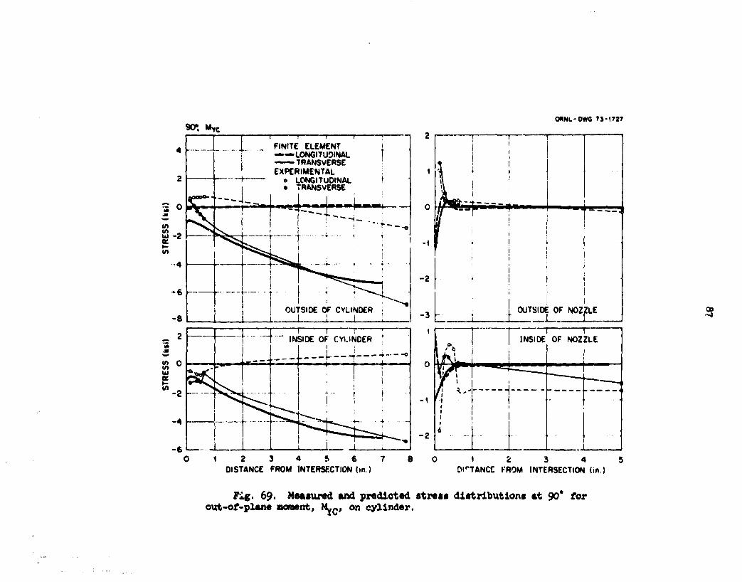
90», MyC
OUNL-OWQ TJ-1727
U) K
"0 (A Ui
to
1 2 3 4 ft 6 7 DISTANCE FROM INTERSECTION (in.)
1 2 3 4 5 Dl"TANCC FROM INTERSECTION (in.)
•2?
Fig. 69. Measured and predicted strew dlatrlbutiona at 90* for out-of-plane moment, MyC, on cylinder.

10 <*••»**: MM.-0W0 T1-I74*
FINITE ELEMENT: —lONGtTUOjNAL
2 4 DISTANCE FROM INTERSECTION (m ) 01 STANCE FROM INTERSECTION (m)
Fig. 70. Measured and predicted stress distributions at 0* for in* plane moment, M-_, on cylinder.
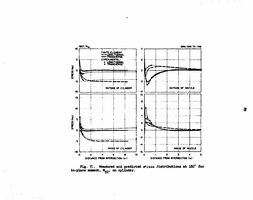
180'. M K OWN.-OW0 T1-IT4*
2 4 6 8 OISTMNCC FROM INTERSECTION tm ) DISTANCE FROM INTERSECTION (in.)
Fig. 71. Measured and predicted 8+r#«» distributions at 180* for in-plane moment, M__, on cylinder.

3<5» M K omi-cm FJ-ITSO
1 2 3 4 DISTANCE FROM INTERSECTION \m)
INSIDE OF NOZZLE
1 2 3 4 DISTANCE FROM WTERSCCTION <m)
Fig. 72. Measured end predicted stress distributions at 315* for in-plane moment, M^, on cylinder.

2 W , ¥ K OftNL-MM T»-lT«t
4 6 6 10 12 DISTANCE FROM INTERSECTION !">>
0 I 2 DISTANCE FROM INTERSECTION U )
Fig. 73. Measured and predicted stress distributions at 270* for in-plane moment, M^, on cylinder.

90*,Mjc OHWL-DWO 7J-1T4T
s
in
6
t 2 3 4 3 6 7 OISTANCE FROM INTERSECTION (to.)
O t 2 3 4 OISTANCE FROM INTERSECTION (in )
Fig. Tk. Measured and predicted stress distributions at 90* for in-plane moment, M ^ , on cylinder.
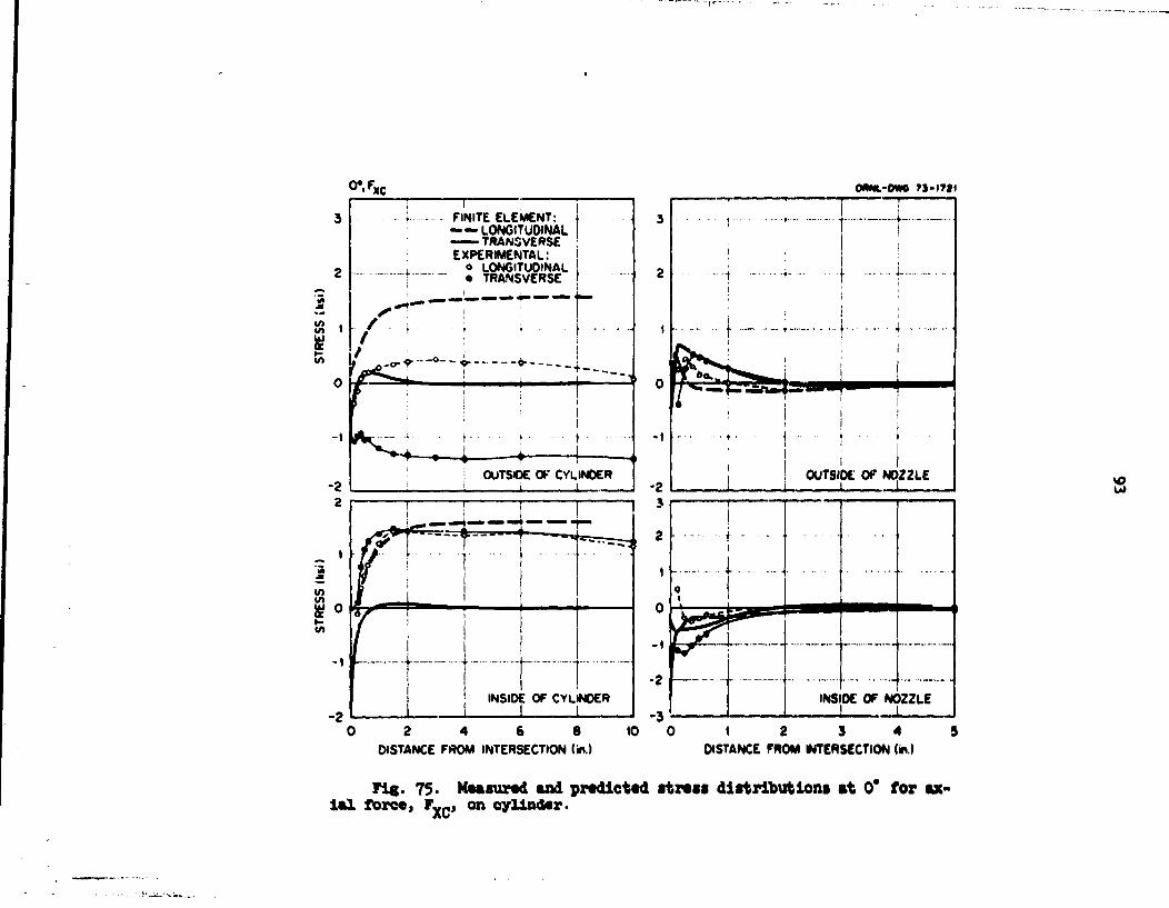
0*.F, OMNt-OWO Ti-ngl
0 2 4 6 8 DISTANCE FROM INTERSECTION (in.)
1 2 3 4 DISTANCE FROM INTERSECTION (in.)
Fig. 75- Measured and predicted atreif distributions at 0* for axial forces Fy C, on cylinder.
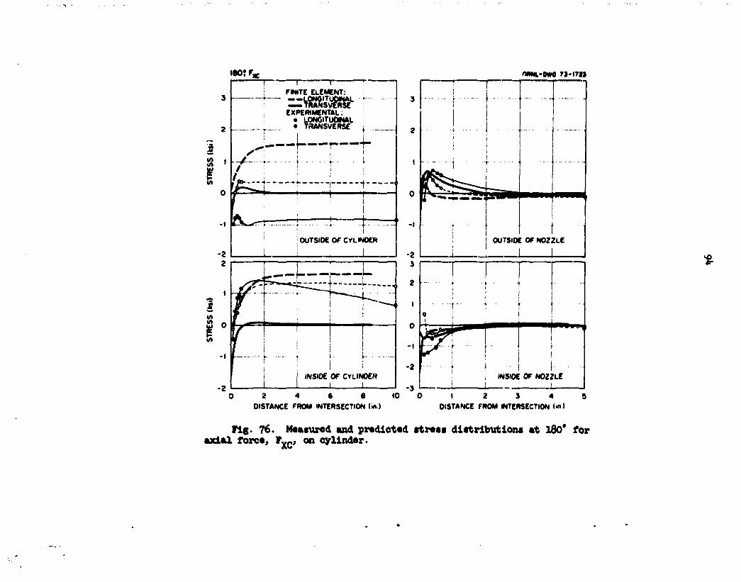
tSOTFg; nftftL-DWO r i - i T i i
3 -
T FINITE ELEMENT:
— --LOIWITupiNAL — TRANSVERSE EXPERIMENTAL.
.ONGlTUOfc . TRANSVERSE
o LONCITUOWAL • in
2 4 6 8 DISTANCE FROM INTERSECTION (in.)
2 \
•i 1
!
r •
sSe*
• —
- • • • • • • -
i • •
i :
( • '
OUTSIDE OF NOZZLE
1 1
•
.. ...
• • •
0 i
" 1 &
\^mm 1 \ i
Y
. •• ! i •• , INSIDE OF NOZZLE
1 2 3 4 DISTANCE FROM INTERSECTION (in >
Pig. 76. Matured and predicted strati distributions at 180* for axial force, FyC> on cylinder.

315*. F w OftNL-OWG 73-1723
1 , FINITE ELEMENT: ——LONGITUQINAL —TRANSVERSE EXPERIMENTAL:
^
-1 I_ r INSIDE OF CYLIUOER
I r - - t 1 2 3 4 5
DISTANCE FROM INTERSECTION (in.)
4
3 \
4 -OUTSIOE OF NOZZLE
i i
1 2 3 4 DISTANCE FROM INTERSECTION U.)
•
f I 1
f f 1
! !
raa-a—
1 1 i 1
1
4
1
1 I 1
l 1 i i
1 U-
i i i
INSIDE OF NOZZLE 1 t
! 1
Fig. 77. Measured and predicted stress distributions at 315* for axial force, F v r, on cylinder.

2*>*.^C omt-om 75-iri4 i 1 ; r~ I FINITE ELEMENT: 1 — — LONGITUDINAL
— T R A N S V E R S E * EXPERIMENTAL:
o LONGITUDINAL • TRANSVERSE
• • • I I I INSIDE OF CYLINDER
_t_
-2
2 4 6 8 tO 12 14 16 DISTANCE FROM INTERSECTION (in.)
" " T
1 i
! !
f. . t . . . I
• - i 1 ! 1 i
t i- i \ \
i |
4... •t OUTSIDE OF NOZZLE
1 I
INSIDE OF NOZZLE
1 2 3 4 (DISTANCE FROM WTERSECTtON(m)
Fig. 78. Measured and predicted street diitributiona at 270* for axial force, F Y r, on cylinder.

>
90*. F. « - I 1 f - —
FWITE ELEMENT:
—MOW!-EXPERIMENTAL:
o LONCITUOINAL • TRANSVERSE
OWNL-DWO ?J- IT I I
6 - • • • •
4 * • •• 1 i
2 1 , ' 1 ••" i
o 1 11 ~£Z3
j
-2 6. I I 1
OUTSIOC OF NOZZLE • • I !
2 3 4 5 6 7 DISTANCE FROM INTERSECTION (in.)
1 2 3 4 DISTANCE FROM INTERSECTION (in.)
Fig. 79* Measured and predicted stress distributions at 90* for axial force, F x c, on cylinder.

0 \ F ONM.-OWG 7S-17M
V F v m n
OUTSIDE OF NOZZLE
*•»"•TV>W 1 - .mmm~mm&mmr**'
INSIDE OF NOZZLE
2 4 6 8 DISTANCE FROM INTERSECTION On )
10 0 1 2 3 4 5 OlSTANCE FROM INTERSECTION On.)
Fig. 80. Measured and predicted stress distributions at 0* for in-plane force, F„ c, on cylinder.

w o * . ^ OMNL-OWS 7 3 - ( T M
FINITE ELEMENT: j —LONGITUDINAL — TRANSVERSE j EXPERIMENTAL,
o LONGITUOINAL • TRANSVERSE
-5 —-!--- - i . _ _ . OUTSIDE OF CYLINDER
J i i
10
V)
-5 -INSIDE OF CYLINDER
"""t
2 4 6 8 DISTANCE FROM INTERSECTION (in.)
10 1 2 3 4 DISTANCE FROM INTERSECTION (in.)
8
Fig. 81, Measured and predicted stress distributions at IdO* for in-plane force, F„ c > on cylinder.

3<»*. F ^
8 # « -2 L
T FINITE ELEMENT: ——LONGITUDINAL — TRANSVERSE EXPERIMENTAL:
o LONGITUOINAL • TRANSVERSE
-4
OUTSIDE 0 - CYLINDER
! i
- — • - • i >
; 1
- ' —r 1
r • - ?
1 !
INSIDE OF CYLINDER i
INSIDE OF CYLINDER
1 2 3 4 5 DISTANCE FROM INTERSECTION (in.)
Oftl-OWS 71-4MO
1 , - - • • •
r* — •
r* — •
* " * - <
<i
i . i i • OUTSIDE OF NOZZLE
_ i i,. i
\
i ! ! i
1 - T t • • • «
, I INSIDE OF NOZZLE i._. . ,L. L
1 2 3 4 DISTANCE FROM INTERSECTION (in.)
8
Fig. 82. Measured and predicted stress distributions at 31?* for in-plane force, F v„, on cylinder.
Xv

270-. Fyc r»-«7|7
FINITE ELEMENT: —-10NGITU0INAL , TRANSVERSE
_t_ EXPERIMENTAL: o L0N6ITU0INAL • TRANSVERSE
2 4 6 8 10 12 14 DISTANCE FROM INTERSECTION («.)
I 2 J 4 DISTANCE FROM INTERSECTION ( * )
Fig. 83. Measured and predicted stress distributions at 270* tor in-plane fore*, F„c, on eylindar.

K) W . F * omi-MKi r i> t?M
FINITE ELEMENT — LONGITUDINAL — TRANSVERSE EXPERIMENTAL.
o LONGITUDINAL • TRANSVERSE
-= ° ^ " ^ J J — — • - A * . 0 f t
I i t
iNSlOE OK CYLINDER
2 J « J 6 T DISTANCE FROM INTERSECTION (m )
L 0
OUTSIDE OF NOZZLE
R M M M W " 1 '
INSIDE OF NOZZLE
DISTANCE FROM INTCRSCCTlONIm,)
Fig. 8U. Meaeured and predicted itrou distribution! tt 90* for in-plane force, Fy., on cylinder.

or F l c OftMfa-OWtt M-(T»(
FINITE ELEMENT: — — LONGITUOINAL
TRANSVERSE EXPERIMENTAL s
o LONGITUOINAL • TRANSVERSE
H • • • • i g i i i m , , . 1 , •••
OOTSIOE OF CYLINDER
v>
5
0
-1
-2
-3
- 4
- 5
fe^^*» ' """
INSIDE OF CYLINOER
2 4 6 6 DISTANCE FROM INTERSECTION (in.)
« 2 3 4 5 OlSTANCE FROM INTERSECTION (m.l
Fig. 85. Measured and predicted stress distributions at 0* for OUt-of-plane force, F z c, on cylinder.

I80*F; OMfc-OWG 7J-I7M
2 4 6 8 DISTANCE FROM INTERSECTION <«.)
©
1 2 3 4 DISTANCE FROM *»T£RSECTtON tin.)
Fig. 86. Measured and predicted stress distributions at 180* out-of-plane force, F 2 C, or cylinder. for

3
2
1
0
- t
-2
* 5 - . F K WML-DWG 75-1782
V. ... I N
FINITE ELEMENT: —LONGITUDINAL
TRANSVERSE EXPERIMENTAL:
o LONGITUDINAL • TRANSVERSE
< * *
-2
-A
10
5
0
•5
-10
-13
-20
- J ••'
- • • • • • • • - - —
- t ..... +............. —-
i i — - f - • • * - - • • — —
— — — • -
—
J . -
i
-t INSIOE OF NOZZLE ..._ .1 .,... 1 1
1 2 3 4 5 DISTANCE FROM INTERSECTION (in.)
1 2 3 4 DISTANCE FROM INTERSECTION (MV)
Fig. 87' Measured and predicted stress distributions at 315* for out-of-plar*e force, F z c, on cylinder.

2T0». F j C OftNL-MN 7I-I7JS
0 2 4 6 8 10 12 14 16 DISTANCE FROM INTERSECTION (in.) DISTANCE FROM INTERSECTION («.»
Fig. 88. Measured and predicted strain distributions at 270* for out-of-plane force, F„„, on cylinder.

90«. F , c 0«*t-0W0 7J.l?»4
in w or
FINITE CLEMCNTi \ — — LONGITUOINAl ! TRANSVERSE
-*"- EXPERIMENTAL! • LONGITUOINAL • TRANSVERSE
g __ .4
I
BM^^p^Mkf
1.5
1.0
0.5
—-*w 0
OUTSIOE OF CYLINDER
1.0
I -OS
INSIOE OF CVLINOCR
OuTSIOC OF N02ZLF
1 2 3 4 5 6 7 DISTANCE FROM INTERSECTION U.)
INSIDE OF NOZZLE
I 8 J 4 9 OtSTANCE FROM INTERSECTION (*.>
Fig. 89. Measured and predicted stress distributions at 90* for out-of-plane force, F-c, on cylinder.

106
R0SRBRES
1. J. M. Const ct a l . , Theoretical and Btperisgntal Stress Analysis of pan. Thin-Shell Cyliiaier-to-Cyliafter it*3el Bo. 1. 0BBL-»553 (October
2. J. M. Const and W. L. Greenstreet, "Experneental Elastic Stress Analy-ses of Cylinder-to-CyUnder Shell Models and Conparisons with Theoretical Predictions," paper So. G2/5, First International Conference on Structural Mechanics in Heactor Technology, Berlin, Sept. 20Sh, 1971.
3. R. C. Qwaltney, J. V. Bryson, and S. E. Bolt, Theoretical and Bxperi-•ental Stress Analysis of OBEX Thin-Shell Cylinder-to-Cylinder Model i o . 3 . 6WL>5oSo7to be pnbiisSaT: *
k. 0. E. Bardenosrgh, S. 1. Zaarik, and A. J. Bfcsurtson, "Experissental Investigation of Stresses in Bossies in Cylindrical Pressure Vessels," Welding Research Council Bulletin 89. July 19S3.
5. D. E. Bardenbergh and S. T. ZaarUt, "Effects of External Loadings on Large Outlets in a Cylindrical Pressure Vessel," Welding Research Council Bulletin 96. May I96W.
6. V. P. Riley, Bxperinental DetersAnation of Stress Distributions in Thin Walled Cylindrical and Spherical Pressure Vessels with Circular Bossies. ITT Research Institute Report Bo. M5053 (March 1965).
7. C. 2. Taylor and B. C. Lind, "Photoelastic Study of the Stresses near Openings in Pressure Vessels," Welding Research Council Bulletin 113. April 1966.
8. M. M. Leven, "Photoelastic Determination of Stresses in Reinforced Openings in Pressure Vessels," Welding Research Council Bulletin 113. April 1966,
9. Ojars Greste, Finite Elenent Analysis of Tubular K Joints. Report UCSESM 70-11, University of California, Berkeley (June 1970).
10. W. Reidelbacb, "The State of Stress at ths Perpendicular Intersection of Two Right Circular Tubes," Ingenieur-Archiv. £0(5), 293-3I6 (1961).
11. A. C. Eringen, A. K. Ragbdi, and C. C. Thiel, "State of Stress in a Circular Cylindrical Shell with a Circular Hole," Welding Research Council Bulletin 102. January 1965.
12. A. K. Haghdi and A. C. Eringen, "Stress Distribution in a Circular Cylindrical Shell with a Circular Cut-Out," Ingenieur-Archiv. 3jf(3J. 161-72 (1965).

109
13. A. C. Eringen and E. S. Suhubi, "Stress Distribution at Two Normally Intersecting Shells," Sucl. Strut*. Ens. 2(3), 253-70 (1965).
Ik. A. C. Eringet et al., "Stress Concentrations in Two Normally Inter* secting Cylindrical Shell* Subject to Internal Pressure," Welding Research Council Bulletin 1*9. April 1969.
15. J. V. Hansberry aid I. Jones, "A Theoretical Study of the Elastic Be-bevior of Two Normally Intersecting Cylindrical Shells," Trans. ASMS, J. Enf. Bad. 9JB(3), 563-72 (1969).
16. R. P. Maye and A. C. Eringen, "Further Analysis of Two Normally Intersecting Cylindrical Shells Subjected to Internal Pressure," Bud. Bng. Das. 12(3), *57-7* (1970).
17. J. H. Hansberry and •- Jones, "Elastic stresses Due to Axial Loads on a Bottle which Intersects a Cylindrical Shell," Second International Conference on Pressure Vessel Technology, Part I, Design and Analysis, pp. 129-5*, October 1973.
18. P. P. Bijlaard, R. J. Dohmnnn, and I. C. Vang, "Stresses in Junction of Bottle to Cylinder Pressure Vessel for Equal Disaster of Vessel and Bottle," Bucl. Eng. Des. £(3), l*H& (1967).
19. K. C. Pan and R. E. Beckett, "Stress and Displacement Analysis of a Shell Intersection,'* Trans. ASMB, J. Eng. Ind. ?2B(3), 303-8 (Msy 1970).
20. L. R. Herrmann and D. K. Campbell, "A Finite-Element Analysis for Thin Shells," AIAA J. 6(10), 18*2-47 (I968).
21. B. Prince and T. R. Rashid, "Structural Analysis of Shell Intersections," presented at First International Conference on Pressure Vessels and Piping, Sept. 29-Oct. 2, .969, Delft, The Nether land*.
22. C. P. Johnson, The Analysis of Thin Shells by a Finite Element Procedure. Report 67-22, Department of Civil Engineering, University of California, Berkeley (September 1967).
23. C. P. Johnson and P. G. Smith, A Compater Program for the Analysis of Thin Shells, Report 69-5, Department of Civil Engineering, University of California, Berkeley (August 1967).
2U. Ojars Grerte, A Computer Program for the Analysis of Tabular K Joints, Report 69-19, Department of Civil Ergineering, University of California, Berkeley (November 1969).
25. R. W. Clough and J. L. Tocher, "Finite Element Stiffness Matrices for the Analysis of Plate Bending," Proceedings of Conference on Matrix Methods in Structural Mechanic*."Report AFFDL-TR-66-80. Wright-Patterson Air Force Base (November 1966).
i

110
26. R. Bailey and R. Hicks, "Localised Loads Applied to a Spherical Pressure Vessel Through a Cylindrical Insert," J. Nech. Sag. Sci. 2(U), 302 (196U).

HI
Appendix
TABULATION OF EXPERIMEHTAL DATA
For the benefit of the reader who would like to use these experimental data to prepare comparisons with his own analysis techniques, the experimental data on which the various plots in this report were based are given in Tables A.l to A.13. For each loading case, a set of data is tabulated for each operable rosette. These data were obtained fro* the several sets of data taken in each case by the procedures described in Sect. 2.k.
The rosette listings are grouped according to gage lines. For each rosette, the three strain readings are listed first, followed by the Dorsal stress transverse (perpendicular) to the gage line, the noraal stress parallel to the gage line, the shear stress (referred to the gage line as a coordinate axis), and the •arfaami and ainiiai principal stresses. The strains are given in Bicroinches per inch, and the stresses are in pounds per square inch.
The nonenclature used to identify and locate each rocette can be explained by considering the following sample designation:
I 180 9-B .
The letter 1 designates that the rosette is located on the inner surface of nozzle or cylinder, an 0 in this position denotes an outside rosette. The number 180 indicates that the rosette is located on the 160* gage line (see Fig. 3 for the gage line designations). The letter 3 indicates that the rosette is on the nozzle; a C in this position designates a rosette on the cylinder; and E designates the location of the rosette along the gage line according to the following convention:
Distance from nozzle-cylinder Rosette intersection (see Fig. 3)
designation (in.)
A *0 B 1/8 C l/'k D 3/8 E 1/2

112
Distance from nozzle-cylinder Rosette intersection (see Fig. 3)
nation ( in.)
F 5/8 G 7/8 H 1 J l 1/2 K 2 L 3 M h H 5 P 6 R 7.85 S 10 T 15.7
In every case, the rosettes were positioned on the gage lines so that the leg of the Y lay along the gage line and pointed away from the nozzle-cylinder junction. The convention used can be understood by referring to Fig. 7. The leg of the ¥ is designated as gage 1 in the tabul- .ions, with gages 2 and 3 being numbered from 1 in the counterclockwise direction.
Finally, in those cases where nonlinearity or drift was excessive or where an individual gage or circuit was otherwise obviously malfunctioning, the rosette of which the gage was a part was not used in the final results plotted in this report for the specific loading under consideration, nonetheless, these data are listed in the tabulations, but they ore marked by an asterisk beside the rosette number.

113
Tiable A . l . In te rna l pressure
IRTEBRiL PRBSSORE (300 PSI)
BICBC-STFAIR STRESSES PRIR STRESSES
ROSETTE GAGE1 C.«GE2 GAGE3 TEARS LORG SHE1R SIGHX SIGHR
I-O-C-C -33 351 360 15658 3696 -127 15659 3695 I-O-C-D 45 286 305 12950 5245 -254 12959 5237 I-O-C-E 76 26C 260 11344 5693 0 11344 5693 I-O-C-F 105 26C 243 10945 6433 222 10956 6422 I-O-C-B 107 2ce 210 9056 5937 -32 9056 5937 I-0-C-.T 88 186 184 8028 5056 32 8029 5056 I-O-C-K 62 172 184 7743 4184 -159 7750 4176 I-O-C-L* -100 165 184 7767 -672 -254 7775 -680 I-C-C-H 50 m 177 7655 3800 -32 7655 3800 I-O-C-P 62 179 179 7799 4 202 0 7799 4202 I-O-C-S 57 189 165 7704 4030 315 7731 4003 0-O-C-B 52 003 434 18336 7062 -410 18351 7047 O-O-C-C • 5 296 310 13284 5334 -190 13289 5329 O-O-C-0 •0 247 261 11103 4535 -189 11108 4530 0-O-C-E 19 228 223 9872 3525 65 9873 3524 O-O-C-F 21 206 194 8777 3267 158 8782 3263 O-O-C-B 21 111 175 7369 2845 -189 7377 2837 O-O-C-J 40 161 154 6879 3265 97 6882 3262 0-O-C-K 57 156 159 6860 3759 -31 6861 3758 O-O-C-L 61 166 168 7274 4024 -32 7274 4023 O-O-C-B 54 168 161 7177 3783 94 7180 3781 O-O-C-P 54 166 15« 7126 3768 127 7130 3763 O-O-C-S 59 159 168 7120 3906 -126 7125 3901 I-O-R-B -352 396 412 18176 -5108 -191 18178 -5110 I-O-R-C 158 30« 297 13037 8654 96 13039 8651 I-O-R-D 18* 184 201 8271 8014 -223 8400 7885 I-O-R-E 117 105 120 4819 4966 -191 5098 4687 I-O-B-P 69 77 91 3608 3166 -191 3679 3095 I-O-R-B 22 72 n 3240 1619 -64 3242 1616 O-O-R-B -67 315 287 13305 1995 379 13318 1982 0-O-R-C -67 68 64 2980 -1105 63 2981 -1106 O-O-R-D 19 14 12 545 726 30 731 540 O-O-R-E 69 19 24 857 2314 -64 2317 854 0-O-R-P 78 35 42 1626 2829 -94 2836 1619 O-O-R-B 64 5S 62 2582 2690 -31 2699 2574 0-O-R-K 35 71 71 3083 1984 -1 3083 1984 O-O-R-B* 21 59 1616 36795 11675 -20749 48489 -19
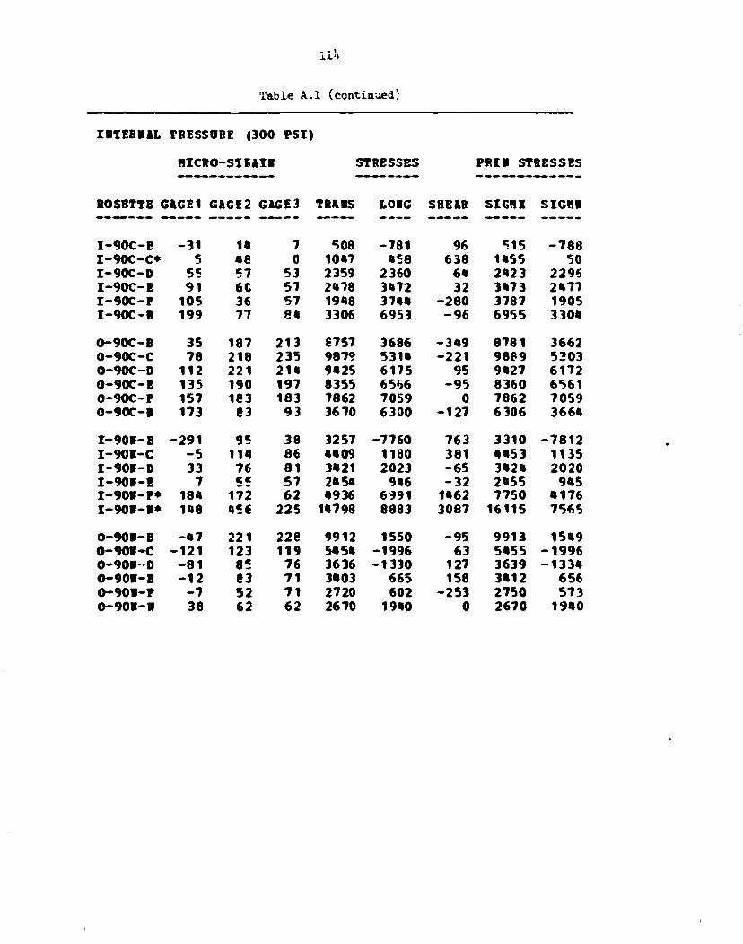
i l H
Table A.l (continued)
IBTEBBiL PBESSOBE (300 PSI)
HICBO-SIEAIB STRESSES PRII STRESSES
BOSBTTE G&GE1 GAGE2 GAGE3 TBABS LOIG SBBIB SIGHI SIGHB
I-90C-E -31 14 7 508 -781 96 515 -788 I-90C-C* 5 48 0 1047 458 638 1455 50 I-90C-D 55 57 53 2359 2360 64 2423 2296 I-90C-E 91 6C 57 2478 3472 32 3473 2477 I-90C-F 105 36 57 1948 3744 -280 3787 1905 I-90C-B 199 77 8« 3306 6953 -96 6955 3304
O-90C-B 35 187 213 €757 3686 -349 8781 3662 0-90C-C 78 218 235 9879 5314 -221 9889 5303 O-90C-D 112 221 214 9425 6175 95 9427 6172 0-90C-E 135 190 197 8355 6566 -95 8360 6561 0-90C-F 157 183 183 7862 7059 0 7862 7059 O-90C-B 173 83 93 3670 6330 -127 6306 3664 I-90B-B -291 95 38 3257 -7760 763 3310 -7812 I-90B-C -5 114 86 4409 1180 381 4453 1135 I-90I-D 33 76 81 3421 2023 -65 3424 2020 I-90B-E 7 cc 57 2454 946 -32 2455 945 I-90B-F* 184 172 62 4936 6991 1462 7750 4176 I-901-B* 148 • 56 225 14798 8883 3087 16115 7565 0-90B-B -47 221 228 9912 1550 -95 9913 1549 0-90B-C -121 123 119 5454 -1996 63 5455 -1996 0-901-D -81 85 76 3636 -1330 127 3639 -1334 O-90I-B -12 83 71 3403 665 158 3412 656 0-90I-F -7 52 71 2720 602 -253 2750 573 0-90B-B 38 62 62 2670 1940 0 2670 1940
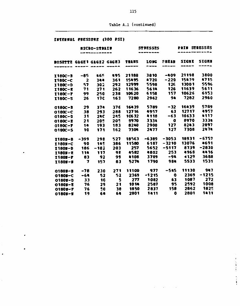
115
Table A.l (continued)
IffTBRffal PRESSURE (300 PSI)
BICBO-STBftIR STRESSES PRIB STRESSES
ROSETTE GAGE1 G1GE2 G1GE3 TRftHS LOHG SHE1R SIGHI SIGHB
I180C-B -85 •65 495 21188 3810 - • 0 9 21198 3800 I180C-C 2 3«« 361 15*95 •720 - 2 2 0 15*59 •715 I180C-D 57 302 292 12999 5598 126 13001 5596 I180C-E 71 271 262 11636 5 6 1 * 126 11639 5611 I180C-F 99 250 238 10620 6158 157 10626 6153 I180C-S 26 17C 163 7280 2962 9 * 7282 2960
0180C-B 29 37* 376 16*39 5789 - 3 2 16*39 5789 0180C-C 38 293 288 12716 *957 63 12717 •957 0180C-0 31 2«C 2*5 1C632 • 118 - 6 3 10633 • 117 0180C-E 21 205 205 3970 333* 0 8970 333« 0180C-P 1« 193 183 82*0 2900 127 82*3 2897 0180C-S 10 171 162 730* 2»77 127 7308 2 *7*
I180R-B -399 298 527 18563 -6389 -3053 18931 -6757 I180R-C 90 1«5 386 11580 6187 -3210 13076 4691 I180H-D 186 -182 203 257 5652 -5117 8739 -2830 I180R-E 11« 117 98 •582 •802 253 • 968 • • 1 6 I180R-P 83 92 99 • 108 3709 - 9 * 4129 3688 I180R-R 7 157 83 527« 1790 98* 5533 1531
0180H-B -78 230 271 11100 977 -5«5 11130 9*7 O180R-C - 6 * 52 52 2369 -1215 0 2369 -1215 0180R-D 33 1G 5 277 1082 63 1087 272 O180R-E 76 29 21 101* 2587 95 2592 1008 0180R-P 76 50 38 1850 2837 158 2862 1825 0 1 8 0 I - I 19 6« 6« 2801 1*11 0 2801 1*11

1 1 * XXIS
Table A.l (continued)
IRTERRAL PRESSORS (300 PSI)
HICRO-SIfAia STRESSED PRIR STRESSES
ROSETTE G16E1 GAGE2 GA6E3 TRARS LOiG SHEAR SIGRX SIGRR
I 2 7 0 C - C 4 • 7 52 2177 784 - 6 4 2180 7 8 1 I 2 7 0 C - D 59 5 * 62 2483 2521 - 9 7 2 6 0 1 2403 I 2 7 0 C - E 97 59 64 2597 3700 - 6 4 3704 2593 I 2 7 0 C - F 133 64 64 2664 4794 0 4794 2664 I 2 7 0 C - H 176 7 1 6 1 2719 6097 128 6102 2715 I 2 7 0 C - J 207 83 93 3636 7304 - 1 2 8 7308 3631 I 2 7 0 C - K * 203 i«e 95 5111 7609 698 7 7 9 1 4929 I 2 7 0 C - L 212 107 90 4097 7590 218 7603 4084 I 2 7 0 C - H 217 10C 93 3987 7694 94 7696 3985 I 2 7 0 C - P 201 93 95 3913 7192 - 2 9 7193 3912 I 2 7 0 C - R 197 105 89 4051 7115 222 7 1 3 1 4035 I 2 7 0 C - T 153 I S 55 1473 5042 - 4 7 9 5105 1410
O270C-B 79 247 238 10578 5529 127 10581 5526 O270C-C 105 228 216 9657 6036 158 9664 6029 0270C-D 133 219 212 9312 6789 95 9315 6785 O270C-E 147 205 195 8721 7039 190 8743 7018 O270C-P 157 19C 176 7875 7071 190 7918 7028 O270C-B 169 159 152 6660 7063 95 7084 6639 O270C-J 190 121 117 5017 7212 63 7214 5015 O270C-K 188 100 100 4183 6890 0 6890 4183 O270C-L 202 IOC 88 3906 7235 158 7 2 * 3 3899 O270C-H 190 9C 83 3608 6793 95 6795 3605 O270C-P 190 8 1 90 3556 6777 - 1 2 7 6782 3551 O270C-R 195 86 90 3655 6950 - 6 3 6951 3654 O270C-T* 183 1C2 0 2047 6110 1363 6525 1632
I 2 7 0 R - B - 3 0 5 60 36 2433 - 8 4 3 5 318 2443 - 8 4 4 4 I 2 7 0 R - C - 5 1C3 98 4411 1180 64 4412 1179 I 2 7 0 R - D 36 1C? 81 4052 2290 318 4107 2234 I 2 7 0 R - E 17 112 48 ?496 1550 859 3820 1225 I 2 7 0 R - P - 7 • 3 41 1849 333 32 1850 332
O270R-B - • 3 237 206 9787 1648 410 9807 1628 O270B-C - 1 2 3 111 114 5082 - 2 1 7 8 - 3 1 5082 - 2 1 7 8 O270B-D - 9 3 7 1 81 3448 - 1 7 4 9 - 1 2 7 3451 - 1 7 5 2 O270R-E - 5 5 59 67 2831 - 7 9 2 - 9 5 2833 - 7 9 5 O270R-P - 3 6 64 67 2914 - 1 9 6 - 3 2 2915 - 1 9 6 O270R-G - 2 6 62 62 2747 39 0 2747 39 O270R-R -2a 57 57 2535 47 0 2535 47 02701 -K 2 43 48 1984 667 - 6 3 1987 664 O270R-R 19 c t 57 2436 1302 - 3 2 2437 1301

117
Table A. l (continued)
IRTEBBAL PRESSURE |300 PSI)
HICBO-StEAIB STRESSES PRIi STRESSES
ROSETTE GAGE1 GAGE2 GAGE3 TBARS LOIG SHEAR SIGHX SIGBB
I 3 1 5 C - B - 7 * 167 315 1C685 9 8 * - 1 9 7 3 11071 598 I 3 1 5 C - C - 1 2 100 325 9357 2 * * 9 - 2 9 9 2 10*72 1 3 3 * I 3 1 5 C - D 55 75 2S2 7790 3987 - 2 7 5 1 9233 25«ft I 3 1 5 C - F 1 7 * 135 18S 7000 7 331 - 6 6 8 7 8 5 * 6477 I 3 1 5 C - H 179 1 3 * 2 1 0 7362 7583 -ioie 8*97 6 « « 8 I 3 1 5 C - J 1 8 * 1*3 198 7 3 0 * 7709 - 7 3 2 8266 6 7 * 7 I 315C-K 1 7 * 1«3 193 7210 7 3 9 * - 6 6 8 7977 6627 I 3 1 5 C - L 132 72 191 56*0 5639 - 1 5 9 2 7231 • 0 * 8 I 3 1 5 C - H 108 83 203 6167 5079 - 1 6 0 7 7320 3927 I 3 1 5 C - P 1 2 * 65 1 9 * 55*1 5 3 9 * - 1 7 2 0 7190 37«6
0315C-B 6« 311 171 10517 5078 1866 11095 • • 9 9 0315C-C 78 297 1«2 9563 5219 2055 10381 • • 0 0 O315C-0 78 320 123 9667 5250 2625 10889 • 0 2 8 0315C-E 59 3 0 1 102 8801 • • 2 1 2656 1005* 3168 0315C-F 83 27e 7 * 7628 • 7 8 0 2719 9 2 7 * 3135 0315C-H 88 2«S 57 6632 • 6 2 * 2561 8379 2877 0315C-K 109 20€ 50 5513 • 9 2 9 2087 7328 3 1 1 * 0315C-L 116 197 57 5*53 5125 1866 7162 3 * 1 6 0315C-H 126 199 6 2 5599 5«53 1 8 3 * 7362 3691 0315C-P 126 187 55 5182 5328 1771 7027 3*83
I 3 1 5 B - B - 2 7 7 1 9 * 213 92*0 - 5 5 5 1 - 2 5 5 9 2 * 5 - 5 5 5 6 I 3 1 5 B - C 69 2 0 1 225 9280 • 865 - 3 1 S 9303 • 8 * 2 I 3 1 5 B - D 103 132 1 * * 5932 • 865 - 1 5 9 5955 • 8 * 2 I 3 1 5 B - S • 8 62 7 2 2891 2303 - 1 2 7 2917 2276 I 3 1 5 B - F 19 • 1 7 2 24*9 1309 - * 1 * 2 5 8 * 117« I 3 1 5 B - H 2« 35 87 2S69 1508 - 6 9 1 2992 1186
0 3 t 5 R - B - 3 3 325 2 1 1 11823 2551 1518 12065 2308 0315B-C - 1 1 2 1 0 * 97 •556 - 1 9 7 9 95 • 557 - 1 9 8 1 O315B-0 - 5 2 23 58 185* - 1 0 0 1 - • 6 7 1929 - 1 0 7 5 0315B-E - 3 9 63 1599 • 0 « - 7 1 7 1935 68 0315H-P 18 19 73 1982 11«8 - 7 2 1 2397 732 0315H-G 21 33 75 2338 1326 - 5 6 5 2590 1 0 7 * 0 3 1 5 3 - H 18 35 73 23*5 1259 - 5 0 0 2 5 * 1 1063 031'5B-R 16 • 9 6 1 2395 1 2 0 * - 1 5 5 2*15 1 1 8 * 0315H-B - • 3 6 1 58 2666 - * 7 8 31 2666 - • 7 9

118
Table A.2. Out-of-plane moment, M „ , on nozzle
O0T-0F-PLANE HORENT LOADING, MEN, ON NOZZLE (100 III-LB)
HTCRO-STRAIN STRESSES PRIN STRESSES
ROSETTE GAGE1 GAGE2 GAGE3 TRANS LONG SHEAR SIGHX SIGHN
I-O-C-C 12 -190 179 -260 288 -4925 4947 -4919 I-O-C-D 0 -169 160 -197 - 5 1 -4385 4262 -4510 I-O-C-E 7 -140 129 -257 143 -3591 3540 -3654 I-O-C-P 7 -114 108 -156 176 -2956 2971 -2951 I-O-C-H 0 62 - 6 4 - 3 9 1 1684 1665 -1704 I -O-C-J 0 39 - 4 3 - 8 8 - 1 5 1080 1029 -1132 I-O-C-K 3 - 2 8 24 - 9 0 57 -703 690 -723 I -O-C-L* 0 - 1 7 14 - 5 2 - 1 6 -413 380 - 448 I-O-C-H 2 - 1 0 10 - 3 71 -254 291 -223 I-O-C-P 2 - 5 5 - 3 71 -127 166 - 9 8 I-O-C-S 2 - 2 5 50 87 - 9 5 165 - 2 9
O-O-C-B 5 - 8 8 7 1 -366 37 -2118 1963 -2292 O-O-C-C 2 - 9 7 88 -203 14 -2464 2372 -2561 O-O-C-D 3 - 8 0 7 1 -204 17 -2023 1932 -2120 O-O-C-E 3 - 6 6 60 -148 34 -1677 1622 -1736 O-O-C-F - 2 - 5 0 52 62 - 4 4 -1358 1368 -1351 O-O-C-H 3 - 2 8 29 7 80 -759 803 -716 O-O-C-J 2 - 1 4 19 102 102 -442 544 - 3 4 1 O-O-C-K 0 - 9 14 104 31 -31S 386 - 250 O-O-C-L 0 - 7 7 0 0 -190 190 -190 O-O-C-R 0 - 5 7 52 16 -158 193 -125 O-O-C-P 0 - 2 2 0 0 - 6 3 63 - 6 3 O-O-C-S 2 0 0 - 3 70 0 70 - 3
I -O-N-B 79 -199 172 -666 2171 -4945 5897 -4392 I-O-N-C - 1 0 - 3 4 - 2 -779 -521 -415 -216 -1084 I-O-N-D - 2 6 7 - 3 4 -5S3 -955 542 -174 -1332 I-O-N-E - 2 4 12 - 1 7 - 7 9 -742 383 96 -917 I-O-N-P - 2 2 5 - 2 76 -624 96 89 -636 I -O-N-N* -153 - 5 0 63 -4579 - 6 4 64 -4579
0-O-M-B - 2 64 - 8 8 -519 -227 2022 1655 -2400 0-O-N-C 2 ttO - 4 5 -107 39 1138 110b -1174 O-O-N-D* 2 749 - 9 16252 4947 10108 22181 -981 0-O-N-E 0 2 0 52 16 32 70 - 3 0-O-N-F 5 0 0 - 5 141 0 141 - 5 0-O-N-H 2 0 - 2 - 5 5 55 32 63 - 6 3 0-O-N-K - 5 0 - 5 - 9 9 -172 63 - 6 3 -208 0-O-N-N* 0 0 0 0 0 0 0 0

Table A.2 (continued)
O0T-0F-PLIHE HOHEMT LOADIHG, HM, OK NOZZLE (BOO IH-LB)
HICRO-STRAIW STRESSES PRIH STRESSES
ROSETTE GAGE1 GAGE2 GAGE3 TRUIS IOHG SHEAR SIGflX SIGHR
I-90C-B -17 -2*7 -227 -10402 -3635 -256 -3625 -10411 I-90C-C* -46 -192 0 -4163 -2624 -2554 -726 -6061 I-90C-D -34 -137 -132 -5866 -2774 -63 -2772 -5867 I-90C-E -31 -98 -91 -4136 -2186 -96 -2181 -4141 I-90C-P -22 -100 -67 -3652 -1754 -4 36 -1658 -3748 I-90C-R 7 2 2 81 226 1 226 81 O-90C-B 76 223 258 10493 5424 -474 10537 5380 O-90C-C 88 199 213 8971 5317 -191 8981 5307 O-90C-D* 85 168 0 3604 3636 2242 5862 1378 O-90C-B 80 123 130 5484 4058 -96 5491 4051 O-90C-P 71 102 102 4400 3450 -1 4400 3450 O-90C-S -3 -5 1 -78 -104 -86 -4 -178
I-^OW-B -591 72 -74 600 -17645 1939 804 -17849 I-90S-C 127 122 122 5214 5364 0 5364 5214 I-90R-D 246 62 100 3294 8358 -508 8409 3244 I-9011-E 215 -5 45 655 6635 -667 6709 582 I-90W-P* 24 -28 3 -588 555 -415 690 -723 I-90W-W 170 8« 48 2700 5895 477 5965 2630
O-90W-3 258 401 403 17388 12968 -31 17388 12967 O-90B-C 59 111 118 4983 3268 -94 4988 3263 0-90R-D 95 14 14 510 2991 1 2991 510 O-90W-E 107 -7 -2 -326 3105 -63 3106 -327 O-90H-P 130 38 5 795 4153 443 4210 738 O-90W-II 130 0 7 13 3918 -95 3921 11

120
Table A.2 (continued)
OOT-OP-PHBB HOBBIT LOADIBG, M B , OB BOZZLB (400 11-LB}
HICBO-STRAIB STBESSES PRIB STRESSES
ROSETTE G&GE1 GAGE2 GAGE3 THAWS LOBG SHEAR SIGBX SIGHS
I180C-B -19 162 -130 730 -357 3893 4118 -3744 I180C-C -12 212 -165 1031 -55 5024 5541 -4565 I180C-D -10 167 -1*2 562 -131 4115 4345 -3914 I180C-E -3 141 -123 397 38 3519 3741 -3306 I180C-P -3 115 -97 401 41 2827 3054 -2611 I180C-S 2 ft -1 71 66 63 131 6 O180C-B 9 85 -100 -340 167 2471 2397 -2570 O180C-C 2 90 -110 -441 -81 2664 2409 -2931 O180C-D a 73 -86 -278 38 2122 2008 -2248 O180C-E 4 61 -65 -72 104 1679 1698 -1666 O180C-P 5 53 -53 -5 142 1402 1472 -1336 O180C-S 22 5 0 81 670 64 677 75 I180B-B -33 246 -172 1662 -503 5561 6245 -5086 I180B-C 2 60 -14 993 370 985 1715 -352 I180B-D 5 24 17 886 409 95 904 391 I180H-E 0 -2ft 12 -262 -79 -477 315 -656 I180W-F 0 -7 4 -65 -30 -159 112 -207 I180N-W 10 2 -2 -10 283 64 296 -24 O180B-B 7 -77 33 -975 -77 -1478 1019 -2071 O180B-C 7 -36 31 -113 181 -892 938 -870 O180W-D 2 -5 12 155 118 -223 360 -87 O180B-E 2 5 0 102 102 64 166 39 0180W-P 0 7 -2 105 32 127 201 -64 O180N-R 2 2 2 102 102 0 102 102

121
Table A.2 (continued)
OOT-OP-PUBE HO HE IT LOIDUG, (III , OB BOZZLE (400 IB-LB)
HICBO-STBAIB STRESSES PBIB STRESSES
ROSETTE GiGEI G1GE2 G1GE3 TBABS LOBG SBE&8 SIGBX SIGBB
I 2 7 0 C - C 6 0 179 179 7797 4128 0 7797 4128 I 2 7 0 C - D • 5 129 124 5506 3012 64 5508 3010 I 2 7 0 C - B 33 93 95 4105 2233 - 3 2 4105 2233 I 2 7 0 C - P 21 69 69 3017 1549 0 3017 1549 I270C-B 5 31 29 1305 535 32 1307 533 I 2 7 0 C - J - 1 0 5 2 168 - 2 3 6 32 170 - 2 3 8 I270C-R - 1 7 - 2 - 7 - 1 9 1 - 5 5 e 64 - 1 8 1 - 5 6 9 I 2 7 0 C - L - 1 7 - 1 0 - 1 0 - 4 0 1 - 6 2 1 0 - 4 0 1 - 6 2 1 I 270C-B - 1 2 - 5 - 7 - 2 4 9 - 4 3 3 32 - 2 4 4 - 4 3 8 I 2 7 0 C - P - 5 2 0 58 - 1 2 6 32 63 - 1 3 1 I 2 7 0 C - H * 101 5 0 - 5 3016 64 3017 - 7 I 2 7 0 C - T 2 7 2 208 134 64 245 97
O270C-B - 1 2 4 - 2 8 1 - 3 0 0 -12630 - 7 5 0 9 255 - 7 4 9 6 - 1 2 6 4 2 0270C-C - 1 1 2 - 1 9 6 - 1 9 3 -8416 - 5 8 9 4 - 3 3 - 5 8 9 4 - 8 4 1 6 O270C-D - 1 0 0 - 1 5 5 - 1 5 8 - 6 7 5 7 - 5 0 3 9 35 - 5 0 3 9 - 6 7 5 7 O270C-E - 8 4 - 1 2 7 - 1 2 4 -5417 - 4 1 3 8 - 3 1 - 4 1 3 7 - 5 4 1 8 O270C-P - 6 9 - 1 0 3 - 9 8 - 4 3 3 7 - 3 386 - 6 4 - 3 3 8 1 - 4 3 4 1 O270C-H - 4 3 - 6 2 - 6 2 -2696 - 2 1 1 2 1 - 2 1 1 2 - 2 6 9 6 O270C-J - 2 0 - 2 5 - 2 7 -1108 - 9 2 2 30 - 9 1 8 - 1 1 1 3 O270C-K - 3 - 5 - 1 0 - 3 3 2 - 1 8 8 64 - 1 6 3 - 3 5 6 0270C-L 9 6 7 275 352 - 1 352 275 O270C-H 11 9 9 384 454 2 454 384 O270C-P 6 U 7 229 261 - 3 3 282 208 O270C-R 4 a 4 185 180 0 185 180 O270C-T 1 - 3 2 - 2 7 35 - 6 4 75 - 6 7
I 2 7 0 B - 8 637 12 43 507 19268 - 4 1 3 19277 498 I270B-C - 6 7 - 1 2 6 - 1 0 7 -5066 - 3 5 2 5 - 2 5 4 - 3 4 8 4 - 5 1 0 7 I 270B-D - 2 2 2 - 8 8 - 9 5 -3795 - 7 7 9 7 95 - 3 7 9 2 - 7 7 9 9 I 2 7 0 B - E - 2 0 3 - 2 6 - 4 8 -1403 - 6 5 0 7 286 - 1 3 8 7 - 6 5 2 3 I270W-P - 1 7 0 10 - 1 2 131 - 5 0 5 1 287 146 - 5 0 6 7
O270B-B - 2 8 4 - 3 4 4 - 3 2 2 -14324 - 1 2 8 2 5 -283 - 1 2 7 7 3 - 1 4 3 7 5 O270H-C - 6 2 - 1 0 9 - 1 1 4 -4825 - 3 2 9 3 63 - 3 2 9 0 - 4 8 2 8 O270W-D - 8 3 - 1 4 - 1 7 - 5 9 7 - 2 6 8 4 32 - 5 9 6 - 2 6 8 4 O270B-E - 1 3 6 7 5 402 - 3 9 5 3 31 402 - 3 9 5 3 O270B-P - 1 5 3 2 7 362 - 4 4 6 8 - 6 2 362 - 4 4 6 9 O270B-G - 1 6 2 0 - 7 16 - 4 8 5 1 95 18 - 4 8 5 3 O270H-H - 1 6 4 0 - 1 2 - 9 1 - 4 9 5 9 158 - 8 6 - 4 9 6 4 O270H-K - 1 6 * - 1 0 7 116 - 4 8 9 9 - 2 2 3 126 - 4 9 0 9 0270W-W - 1 6 4 0 - 1 0 - 4 3 - 4 9 4 8 127 - 4 0 - 4 9 5 1

Table A.2 (continued)
OOT-OF-PLARE HORERT LOADIRG, (IIR, OR ROZZLE («00 IR-LB)
HICRO-STRIIR STRESSES PRIR STRESSES
ROSETTE GAGE1 GAGE2 GAGE3 TRARS LORG SHEAR SIGHX SIGRR
I315C-B 41 41 284 7091 3345 -3245 8965 1472 I315C-C 33 12 2 7 5 6260 2881 -3499 8456 684 I315C-D 31 5 191 4272 2213 -2479 5927 558 I315C-P 50 41 86 2726 2322 -604 3161 1887 I315C-H 62 41 100 3028 2771 -795 3705 2093 I315C-J 60 45 86 2820 2637 -541 3277 2180 I315C-K 53 48 76 2671 2377 -382 2933 2115 I315C-L 0 2 36 836 251 - 441 1072 14 I315C-H - 5 8 21 657 45 -174 703 - 1 1315C-P - 5 0 2 47 -147 - 2 5 51 -150
0315C-B - 5 5 -228 - 6 4 -6353 -3543 -2181 -2353 -7542 0315C-C - 5 0 -199 - 4 7 -5367 -3105 -2023 -1918 -6554 0315C-D - 3 8 -209 - 4 7 -5589 -2816 -2149 -1644 -6760 0315C-B - 2 6 -176 - 4 5 -4820 -2229 -1738 -1356 -5693 0315C-F - 2 8 -145 - 3 3 -3879 -2018 -1486 -1195 -4701 0315C-H - 1 4 -109 - 3 1 -3060 -1345 -1043 -852 -3553 0315C-K - 7 - 4 5 - 2 1 -1452 -649 -316 -540 -1561 0315C-L - 7 - 2 4 - 1 7 -878 -477 - 9 5 -456 -900 0315C-H - 7 - 9 - 1 2 -461 -352 32 -343 -470 0315C-P - 2 2 - 2 3 - 7 0 63 39 -107
I315R-B 440 -136 79 -1749 12664 -2865 13213 -2297 I315R-C - 6 2 - 9 6 -108 -4408 -3195 160 -3175 -4428 I315R-D -165 - 5 1 - 9 4 -2984 -5851 573 -2874 -5961 I315R-B - 1 * 9 - 1 2 - 4 3 -1059 -4774 412 -1014 -4819 I315R-F -125 0 - 1 7 -245 -3812 222 - 231 -3826 I315R-R -125 4 11 480 -3591 - 9 6 482 -3593
0315W-B -209 -218 -368 -12648 -10058 1991 -8977 -13728 0315R-C - 3 6 - 5 7 - 128 -4027 -2276 948 -1861 -4442 0315R-D - 5 6 5 ^6 -393 -1801 404 -286 -1909 0315R-E - 9 1 16 3 516 -2586 185 521 -2597 0315R-F - 1 1 2 10 5 444 -3237 63 445 -3238 0315R-G - 1 2 2 3 - 4 96 -3623 95 98 -3626 0315R-H -117 3 - 7 34 -3502 125 38 -3506 0315R-K -117 3 - 1 1 - 6 5 -3533 186 - 5 5 -3543 0315R-R* -618 10 - 1 1 640 -18353 281 644 -18357

123
Table A. 3 . Torsional atoeent loading, H^,. on nozzle
TORSIORAL ROBERT LCADIRG, HTR, OR ROZZLE (1600 IH-LB)
HICRO-STMIR STRESSES PRIR STRESSES
ROSETTE • GAGE1 GAGE2 GAGE3 TRARS L O K SHEAR S I G H I SIGHR
I - O - C - C 7 - 2 * • 7 499 3 5 * - 9 5 * 1383 - 5 3 0 I - O - C - D 2 - 2 7 • 7 • 5* 198 - 9 8 6 1320 - 6 6 8 I - O - C - E 2 - 2 2 35 297 1 5 * - 7 6 3 992 - 5 * 0 I - O - C - F 0 - 1 7 28 251 66 - 6 0 3 768 - • 5 1 I - O - C - H - 3 19 - 1 0 197 - 2 7 381 * 8 3 - 3 1 2 I - O - C - J 0 I f - 1 0 137 28 350 «37 - 2 7 2 I - O - C - K 2 _ c 11 13* 98 - 2 1 9 335 - 1 0 * I - O - C - L * - 1 1 2 _ c 9 207 - 3 3 0 0 - 1 9 0 217 - 3 3 1 1 I - O - C - H 2 - 3 9 138 99 - 1 6 0 280 - * ? I - O - C - P 2 - 1 « 76 79 - 6 1 138 16 I - O - C - S 2 - 1 3 *0 61 - * 2 9 * 7
0 -O-C-B - 9 192 - 2 3 0 - 8 1 3 - 5 1 7 5619 * 9 5 6 - 6 2 8 6 O - O - C - r - 2 5C - 8 5 - 7 5 9 - 2 9 0 1801 1292 - 2 3 * 1 O-O-C-D - 2 31 - 5 6 - 5 5 * - 2 2 2 1166 790 - 1 5 6 6 0 - O - C - E - 2 17 -*o - * 9 * - 2 0 3 753 * 1 9 - 1 1 1 6 O-O-C-P 1 8 - 3 0 - 5 0 * - 1 3 3 506 220 - 8 5 7 0 -O-C-H - 2 "5 - 1 6 - 2 8 8 - 1 * 2 252 * 7 - « 7 8 0 - O - C - J - 2 0 - 6 - 1 2 9 - 8 6 90 - 1 5 - 2 0 0 O-O-C-R - 2 — 2 -a - 1 2 9 - 9 0 31 - 7 3 - 1 * 6 0 - O - C - L - 2 - 2 - * - 1 3 2 - 8 8 32 - 7 1 - 1 5 0 o-o-c-n - 2 1 -a - 8 0 - 7 7 6* - 1 * - 1 * 3 O-O-C-P - 2 — 2 - 2 - 8 2 - 7 7 - 2 - 7 6 - 8 2 0 -O-C-S - 2 — 2 - 2 - 8 0 - 7 0 0 - 7 0 - 9 0
T-O-R-B 57 - 2 1 3 220 8a 17*0 - 5 7 7 5 6 7 * 6 - * 9 2 3 I - C - R - C - 2 2 - 3 1 9 306 - 2 * 6 - 7 3 2 - 8 3 2 9 7 8 * * - 8 8 2 1 I - O - R - D - 3 1 - 3 3 5 309 - 5 * 9 - 1 1 0 8 - 8 5 8 3 7759 - 9 * 1 6 I - O - R - E - 3 9 - 3 2 6 337 300 - 1 0 6 9 - 8 8 36 8*79 - 9 2 * 7 I - O - R - P - 3 * - 3 2 6 3*C 3«a - 9 0 9 - 8 8 7 2 8612 - 9 1 7 7 I - C - R - R 2ft - 3 * 8 335 - 3 0 * 619 - 9 0 9 * 9263 - 8 9 * 8
0 -O-R-B 5 HO2 - 0 9 3 -1966 - * 3 » 119*1 10765 - 1 3 1 6 5 0-O-W-C 20 "i9« - * 1 7 - 5 1 1 * 3 2 10805 10776 - 1 0 8 5 5 O-O-R-0 8 373 - * 3 3 - 1 3 * 3 - 1 7 3 10738 9996 - 1 1 5 1 2 0 -O-R-E 10 375 -uia - 8 8 2 35 10517 10103 - 1 0 9 5 0 0 -O-R-P 15 387 -am - 6 2 3 256 10670 10*96 - 1 0 8 6 2 0 -O-R-H - 1 6 * 1 - - 3 9 5 395 - 3 6 7 10766 10787 - 1 0 7 5 8 0-O-R-K - 9 * 0 1 - 3 9 8 12* - 2 2 5 1067* 1 0 6 2 * - 1 0 7 2 6 0-O-R-R - 5 2 401 - 3 7 0 7 3* - 1 3 3 1 1027* 10028 - 1 0 6 2 5

Table
TCRSIOB&L ROBERT LCftDIBG,
HICB0-S1UIC
BOSETTE GAGE1 GAGI2 G1GE3
I -90C-B - 7 - 6 9 • 5 I -90C-C* - 1 0 - 1 1 ? 0 I -90C-D - 7 - 9 6 91 I - 9 0 C - E - 2 - 7 4 72 I - 9 0 C - P - 2 - 2 9 55 I -90C-B 2 C 0
O-90C-B - 1 8 138 - 8 e
O-90C-C - 4 74 - 5 2 O-90C-D - 2 57 - • 0 O-90C-E - 4 5C -3e O-90C-P - 2 48 - 3 8 O-90C-B - 2 - « - 4
I - 9 0 I - B - 9 ? - 2 7 0 303 I -90R-C - 4 8 - 3 1 0 408 I -90R-D - 6 2 - 3 2 6 412 I - 9 0 R - E - 6 6 - 3 3 8 400 I - 9 0 R - F 11 _ e 2 I - 9 0 B - B * 86 - 1 7 6 117
O-90R-B •5 • 37 - • 2 0 O-90R-C 22 373 - 3 9 8 O-90R-D 2 * 385 - 3 9 6 O-90R-B* 89 390 - 2 0 8 O-90R-F 91 212 - 2 * 2 O-90R-B* 91 36€ - 2 5 1
12U
A.3 (continued)
HYW, OB ROZZLB (1600 IR-L9)
STRESSES PRIH STRESSES
TB1BS LOBG SHEAR SIGRI SIGHB
- 5 1 9 - 3 7 1 - 1 5 3 0 1088 - 1 9 7 6 2513 - 1 0 4 1 - 1 5 3 0 - 7 9 - 3 4 7 5
- 9 7 - 2 * 5 -2ft 87 2317 - 2 6 5 8 - 5 0 - 8 7 - 1 9 4 5 1876 - 2 0 1 3 581 103 - 1 1 1 6 1483 - 7 9 9
- 3 71 0 71 - 3
1193 - 1 8 9 2972 3553 - 2 5 4 9 08a 13 1677 1942 - 1 4 4 5 383 54 1294 1523 - 1 0 8 6 276 - • 9 1171 1296 - 1 0 6 8 220 2 1138 1255 - 1 0 3 3
- 1 7 2 - 1 1 2 - 1 0 - 1 1 0 - 1 7 4
843 - 2 5 2 1 - 7 6 3 1 6975 - 8 6 5 4 2190 - 7 8 2 - 9566 10387 - 8 9 7 5 1957 - 1 2 5 9 - 9 8 4 6 10325 - 9 6 2 7 1039 - 1 5 5 9 - 9 8 4 3 9897 - 1 0 0 1 7 - 8 3 31ft - 9 4 335 - 1 0 4
1386 2176 - 3 9 1 3 469ft - 3 9 0 4
370 265 11413 11730 - 1 1 0 9 5 -58ft ft7tt 1027ft 10232 - 1 0 3 4 2 - 2 7 3 691 10ft 00 1059ft - 1 0 2 2 5 3992 3860 8029 11956 - 4 1 0 3 - 7 5 3 2«99 6039 7128 - 5 3 8 1 2128 3450 8218 11173 - 5 2 9 5

125
"able A.3 {contin-jed}
TORSIOHL ROflElT LCI D U G . BT1, 0 1 •OZXLE (1600 IK-LB)
f l l C H O - S l l l I l STRESSES P i l l STRESSES
ROSETTE GAGE1 G1GE2 GAGE3 TRARS L01G SBEAR SIGSV SIGH!
I 1 8 0 C - B 0 -1"? - 2 « - 8 8 1 - 2 6 « 9« - 2 5 0 - 8 9 5 I 1 8 0 C - C 0 - • 5 7 - 8 2 9 - 2 « 9 - 6 9 1 211 - 1 2 8 8 I 1 8 0 C - 0 5 - 3 3 9 -523 - 1 6 - 5 6 5 350 - 8 8 9 I 1 8 0 C - E 5 - 2 8 7 - • 7 1 0 - • 7 1 291 - 7 6 2 I 1 8 0 C - P 2 - 2 1 c - 3 6 5 - 3 9 - 3 * 5 180 - 5 8 « I 1 8 0 C - S 0 — 2 2 0 0 - 6 3 63 - 6 3
O180C-B 12 2 1 1 - 2 0 2 250 • 3« 55«8 5890 - 5 2 0 6 0180C-C 2 93 - 5 7 78a 308 1997 2557 - 1 * 6 5 0180C-D 2 62 - 3 6 «i7« 2«6 1300 1720 - 9 0 0 0180C-E 0 • 3 - 2 9 • 20 128 887 1173 - 6 2 5 0180C-P 2 33 - 1 C 503 210 571 9«6 - 2 3 2 0 1 8 0 C - S * - 8 ~2 2 97 - 1 9 7 - 2 97 - 1 9 7
I 1 8 0 1 - B - 2 1 - 1 5 « 165 267 - 5 » 1 - • 2 5 2 • 135 - • • 0 8 I 1 8 0 1 - C 9 1 - 3 " 268 - 2 0 1 2 2132 - 8 2 8 9 9604 - 8 « 8 » I 1 8 0 1 - D 101 - 2 8 1 2«6 - 8 6 8 2 7 6 * - 7 0 1 9 8198 - 6 3 0 3 I 1 8 0 1 - E 98 - 3 9 7 306 - 2 1 2 3 2313 - 9 3 6 9 9722 - 9 5 3 3 I 1 8 0 1 - P 10« - « 1 5 325 - 2 0 8 2 2»87 - 9 8 6 2 10325 - 9 9 2 1 I 1 8 0 1 - 1 * 203 -U3S 218 - 5 0 6 1 • 5 7 9 - 8 f 3 3 9739 - 1 0 2 1 6
01801-B - 2 9 • 58 - 2 9 3 3662 23» 9997 12092 - 8 1 9 5 01801-C - 2 2 • 6 3 - 3 7 6 19*6 - 6 6 11182 12167 - 1 0 2 8 7 O1801-D - 5 • 35 - 3 6 9 1058 285 10706 11593 - 9 8 5 1 01801 -B - 7 * * 2 - • 0 2 1099 105 11371 1198« - 1 0 7 7 9 01801 -P - 1 7 • 37 - 3 9 7 903 - 2 3 3 11120 11tt70 - 1 0 7 9 9 0 1 8 0 1 - 1 16 • 09 - 3 8 8 • 37 619 10613 11111 - 1 0 0 8 5
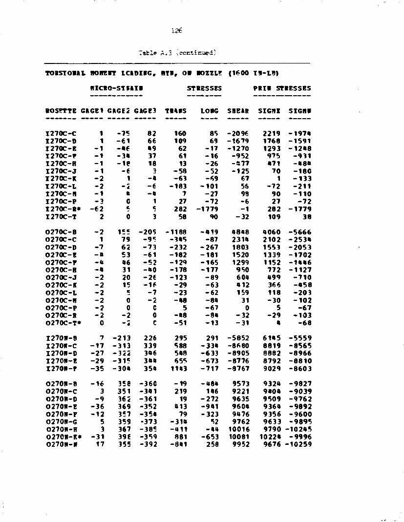
126
i ib l e A.3 -iecntiirjed)
TORSTORAL ROBERT ICiDIRG, HTR, 0 1 ROZZLE (1600 Tl-LB)
fllCRO-STMIH STRESSES PRIR STRESSES
ROSETTE GftGEI GHGE2 G»GE3 TIMS LORG SHEAR SIG71Z SIGHR
I 2 7 0 C - C 1 - 7 5 82 160 85 - 2096 2219 - 1 9 7 4 I 2 7 0 C - D 1 - 6 1 66 109 69 - 1 6 7 9 1768 - 1 5 9 1 I 2 7 0 C - E - 1 - 4 6 49 62 - 1 7 - 1 2 7 0 1293 - 1 2 4 8 I 2 7 0 C - F - 1 - 3 4 37 61 - 1 6 - 9 5 2 975 - 9 3 1 I 2 7 0 C - H - 1 - i e 18 13 - 2 6 - 5 7 7 471 - • 8 4 I 2 7 0 C - J - 1 - 6 3 - 5 8 - 5 2 - 1 2 5 70 - 1 8 C I 2 7 0 C - K - 2 1 - 4 - 6 3 - 6 9 67 1 - 1 3 3 I 2 7 0 C - L - 2 — 2 - 6 - 1 8 3 - 1 0 1 56 - 7 2 - 2 1 1 I 2 7 0 C - H - 1 a - 4 7 - 2 7 98 90 - 1 1 0 I 2 7 0 C - P _3 0 1 27 - 7 2 - 6 27 - 7 2 I 2 7 0 C - R * - 6 2 K c 282 - 1 7 7 9 - 1 282 - 1 7 7 9 I 2 7 0 C - T 2 0 3 58 90 - 3 2 109 38
O270C-B - 2 155 -20S - 1 1 8 8 - 4 1 9 4818 4060 - 5 6 6 6 O270C-C 1 79 - 9 5 - 3 4 5 - 8 7 2314 2102 - 2 5 3 4 O270C-D - 7 62 - 7 3 - 2 3 2 - 2 6 7 1803 1553 - 2 0 5 3 O270C-E - a 53 - 6 1 - 1 8 2 - 1 8 1 1520 1339 - 1 7 0 2 O270C-F -a 46 - 5 2 -12<» - 1 6 5 1299 1152 - 1 4 4 6 O270C-H -a 31 -HO - 1 7 8 - 1 7 7 950 772 - 1 1 2 7 O270C-J - 2 20 - 2 6 - 1 2 3 - 8 9 604 499 - 7 1 0 O270C-R - 2 15 - 1 6 - 2 9 - 6 3 412 366 - 4 5 8 O270C-L - 2 c - 7 - 2 3 - 6 2 159 118 - 2 0 3 O270C-H - 2 0 - 2 - 4 8 - 8 4 31 - 3 0 - 1 0 2 O270C-P - 2 0 C 5 - 6 7 0 5 - 6 7 O270C-R - 2 - 2 0 - 4 8 - 8 4 - 3 2 - 2 9 - 1 0 3 O270C-T* 0 ^
- < C - 5 1 - 1 3 - 3 1 4 - 6 8
I 2 7 0 R - B 7 - 2 1 3 226 295 291 - 5 8 5 2 6145 - 5 5 5 9 I 2 7 0 R - C - 1 7 - 3 1 3 339 588 - 3 3 4 - 8 6 8 0 8819 - 8 5 6 5 I 2 7 0 R - 0 - 2 7 - 3 2 2 346 548 - 6 3 3 - 8 9 0 5 8882 - 8 9 6 6 I 2 7 0 R - E - 2 9 - 3 1 5 344 655 - 6 7 3 -8776 8792 - 8 8 1 0 I 2 7 0 R - P - 3 5 - 3 0 4 354 1143 - 7 1 7 - 8 7 6 7 9029 - 8 6 0 3
O270R-B - 1 6 35e - 3 6 0 - 1 9 - 4 8 4 9573 9324 - 9 8 2 7 O270R-C 3 351 - 3 4 1 219 146 9221 9404 - 9 0 3 9 O270R-D - 9 362 - 3 6 1 19 - 2 7 2 9635 9509 - 9 7 6 2 O270R-E - 3 6 369 - 3 5 2 413 - 9 4 1 9604 9364 - 9 8 9 2 O270R-P - 1 2 357 - 3 5 4 79 - 3 2 3 9476 9356 - 9 6 0 0 O270R-G 5 359 -373 - 3 1 4 52 9762 9633 - 9 8 9 5 O270H-H 3 367 - 3 8 5 - 4 1 1 - 4 4 10016 9790 - 1 0 2 4 5 O270H-K* - 3 1 396 - 3 5 9 881 - 6 5 3 10081 10224 - 9 9 9 6 O270H-R 17 355 - 3 9 2 - 8 4 1 258 9952 9676 - 1 0 2 5 9

127
Table A.3 (continued)
TOISIOUL IK3 HE IT L C I D I K , BYf. Of BOZZLZ (1600 I I - I B )
HICBO-STBIIB STRESSES P i l l STIESSES
SOSETTE G1GE1 GAGE2 GAGE3 TtABS LOBC SBEit SIGBX SIGH*
I 3 1 5 C - B 0 3 1 101 2901 876 - 9 2 5 3260 517 I 315C-C c c 113 2582 926 - 1 « 3 1 3«08 101 I 3 1 5 C - 0 7 2 7B 1679 718 - 9 5 8 2270 127 I 3 1 5 C - F • 3 29 B1 1*91 1 7 * 8 - 1 5 9 1 8 2 * 1 M B I 3 1 5 C - B 27 20 39 1253 1177 - 2 5 6 1B73 956 I 3 1 5 C - J 22 20 31 1098 987 - 1 5 9 1211 8 7 * I 3 1 5 C - I 17 17 24 890 783 - 9 5 9 * 6 727 I 3 1 5 C - L - 5 - 2 12 215 - 7 9 - 1 9 1 309 - 1 7 3 I 3 1 5 C - B 0 c 110 - 1 1 0 - 6 4 127 - 1 2 7 I 3 1 5 C - P - 2 0 6 3 - 7 1 0 3 - 7 1
0315C-B 53 155 - * 7 2312 2279 2687 • 9 8 3 - 3 9 2 0315C-C • 8 96 - • 200* 20«1 1356 3379 666 O315C-0 55 17 - 7 8 - 1 3 9 9 1232 1265 17«2 - 1 9 0 8 0315C-B - 2 1 3 - 6 6 - 1 1 6 6 - 1 0 « 2 917 - 2 7 3 - 2 1 3 5 0315C-F - 2 1 3 - 6 1 - 1 2 5 1 - 1 0 0 2 863 - 2 5 5 - 1 9 9 8 0315C-H - 1 8 - 1 1 - • 7 - 1 2 6 1 - 9 2 7 • 7« - 5 9 1 - 1 5 9 7 0315C-K - I B - I B - 2 3 - 8 0 0 - 6 5 0 12B - 5 8 0 - 8 7 0 0315C-L - 1 1 - 6 - 1 % - • 2 8 - • 6 « 9» - 3 5 0 - 5 * 2 0315C-H - 7 - • - 9 - 2 8 7 - 2 8 6 65 - 2 2 1 - 3 5 2 0315C-P - 2 — i - 7 - 1 8 1 - 1 1 0 66 - 7 0 - 2 2 1
I 3 1 5 P - B 8« - 2 2 0 280 1222 2877 - 6 6 5 7 8758 - • 6 5 9 I 3 1 5 I - C 0 - 3 1 6 311 - 1 0 5 - 3 2 - 8 3 « 5 8277 -8B1B I 3 1 5 I - D - 1 7 - 3 3 5 316 - • 0 2 - 6 2 3 - 8 6 6 « 8152 - 9 1 7 7 I 3 1 5 I - E - 1 2 - 3 3 2 316 - 3 5 5 - • 6 5 - 8 6 3 2 8223 - 9 0 * 2 I 3 1 5 B - P - 2 « - 3 3 9 330 - 1 8 « - 7 7 2 - 8 9 1 9 B M 6 -9M>2 1 3 1 5 1 - i * 59 - 2 6 B 299 712 1982 - 7 5 0 6 8880 - 6 1 8 6
0315B-B * 2 3B0 - • 7 9 - 3 1 1 7 629 10909 982B - 1 2 3 1 3 0315P-C 60 352 - 3 8 9 - 8 8 5 1528 98 6« 10259 - 9 6 1 7 0 3 1 5 I - D 87 357 -39B - 9 1 8 2333 10008 108*6 - 9 » 3 1 0 3 1 5 I - E 59 380 - 3 7 1 m 1806 10008 11017 - 9 0 6 8 0315W-F 35 376 - 3 8 0 - 1 3 8 1018 10071 10528 - 9 6 * 8 0315H-G 26 373 - 3 6 6 130 817 9852 10332 - 9 3 8 5 0 3 1 5 8 - 1 2 * 387 - 3 6 6 • • 2 8«0 100«0 10682 - 9 » 0 1 0315B-K 21 371 - 3 7 5 - 1 2 2 600 9946 10191 - 9 7 1 « 0315B-B - 5 1 362 - 3 8 7 - 5 0 7 - 1 6 8 1 9977 8 9 0 1 - 1 1 0 8 9

1 9 «
Ttble A-1*. Ia-plane w e n t loading, M^, on nozzle
i t - m i i BOUHT L C U I K . «•> oo MSSLI C«OO H - L H
•IOO-SYIAZI STI1SSBS P i l l STIES SIS
•0S1TTB CICE1 68612 C16B3 mis 1 0 K SBB8B s icn SI O i l
I -O-C-C - 3 0 -110 - 1 2 9 -5198 -2700 258 -2676 -5219 ! - • - € - • - 7 •01 - 1 0 2 -8023 - 1 8 t 9 206 -1300 -6056 I - l - C - B 10 - € 2 - 7 9 -3090 - 6 8 1 222 - 6 2 1 -3110 I - l - C - f 22 - 5 0 - 6 8 -2536 -118 190 - 9 9 -2551 I - O - C - l 3* - 3 6 - 3 1 -1899 557 - 6 8 559 - 1 5 0 1 i-«-c-a 26 - 2 6 - 1 9 -1010 806 - 9 6 892 -1026 I - « - C - I 17 - 1 7 - 2 1 -050 251 62 258 - 0 5 3 I - l - C - l * -162 - 1 2 - 1 7 -862 -5802 68 -861 -5003 I - O - C - l 0 - 7 - 10 -376 - 1 2 0 31 -116 - 3 7 9 I - « - C - t 0 - 7 - 5 - 276 - 9 1 - 3 1 - 0 6 - 2 0 1 I -O-C-S - 3 - 3 - 6 -186 -127 10 -116 - 1 5 7
o-«-c-i 66 256 261 11209 5301 - 6 8 11290 5 300 o-o-c-c •0 171 176 7560 3801 - 6 3 7560 3800 0-«-C-D 19 130 133 5766 2302 - 3 2 5767 2302 O-O-C-E -2 109 102 8685 1325 98 8680 1323 0-O-C-F -7 00 70 3659 000 126 3668 002 O-O-C-l -16 •5 85 2000 176 0 2000 176 O-O-C-J - 1 * 21 17 058 -166 62 050 - 1 7 0 0-O-C-E -5 12 10 879 5 32 881 3 0 - O - C - l 0 5 5 212 60 0 212 60 o-o-c-i 0 5 5 212 67 0 212 67 O-O-C-F -2 0 0 6 -66 0 6 -66 o-o-c-s -2 0 0 7 - 6 5 0 7 - 6 5
I - 0 - 1 - B -098 50 89 3602 -13057 - 5 1 1 3617 -13872 I - O - l - C 70 110 117 8925 3565 - 9 6 •932 3558 1 - 0 - 1 - 0 201 61 88 3811 7061 - 3 2 7061 3611 I - O - l - E 192 26 31 1002 6050 - 9 6 6052 1000 I - O - l - F 158 0 10 80 8755 -127 6759 37 1 - 0 - 1 - 1 * - 1 9 - 5 0 - 79 -595 - 6 8 - 7 1 - 6 0 3
0 - 0 - 1 - 1 197 267 205 12389 9613 32 12389 9613 O-O-l -C 6* 83 81 3532 2908 32 3533 2902 0 - 0 - 1 - 0 100 5 5 102 3021 1 3021 102 0 - 0 - 1 - B 1*0 - 1 7 - 7 -672 3997 -126 6001 - 6 7 6 O - o - l - P 15* ~1"» - 5 -635 8835 -156 6*80 - 6 8 0 O - O - l - l 16* 5 0 -73 8888 63 6888 - 7 6 0 - 0 - 1 - E 161 5 - 2 -123 8803 95 W605 - 1 2 5 O - O - l - l * 168 1 * -1761 -30572 -6521 23655 6026 -51119

129
Table A-fc (continued)
IB-NABE BOOR L00BIB6, B I , 06 P0XZL8 f«00 IB-LB)
BICBO-STBUB ST1ESSBS R H STIES SIS
BOSBTTB 606B1 616E2 6B6B3 TIIBS LOB6 SBBBB S I6BI S I 6 B I
I-90C-B 12 112 - 7 9 723 570 2550 3201 - 1 9 0 2 I -90C-C* 12 105 0 3015 1003 2200 •902 70 I -90C-B 10 130 -13*3 02 300 3002 3775 - 3 0 3 0 I-90C-B 2 112 - 1 1 7 -100 39 3000 3027 -3095 I-90C-B 5 90 - 9 0 -50 120 2502 2010 -2550 I-90C-B - 2 0 0 3 - 7 1 0 3 - 7 1
O-90C-B - I f 2« - 6 0 -912 - 0 3 9 1201 320 -2077 o-9oc-c - 1 2 10« - 9 3 200 -205 2023 2020 -2007 0-90C-B - 7 7 * - 0 9 152 -177 1930 1925 -1950 0-90C-B - 7 SO - 5 0 0 - 2 2 2 1327 1221 - 1 M 2 o-9oc-r - 7 33 - • 0 -150 -200 979 770 -1192 O-90C-B 0 0 - 3 - 0 1 - 3 3 • 0 - 1 0 - 1 0 0
I-90B-B 117 122 -106 -055 3303 3501 5390 - 2 7 5 0 I -90B-C - 3 1 - 2 1 - 1 9 -055 - 1 1 0 * - 3 2 -052 -1107 I -90B-B - 5 0 - 3 0 24 -207 -1502 -790 100 - 1 9 2 9 I -90B-B - 3 0 - 1 0 12 - 10 -1140 -3ft9 09 -12»« I -90B-F - 2 1 - 1 7 17 29 - 029 -««0 250 - 0 5 3 I - 9 0 B - I 21 12 12 • 0 * 779 0 779 0 0 *
0-99B-B - 3 - 5 5 52 - 50 - 9 0 - 1 * 2 2 13*5 -1500 O-90B-C - 5 - 3 0 35 -50 -107 -979 000 -1093 O-90B-0 - 5 - 1 2 9 -50 -109 -203 175 - 0 0 3 0-90B-B 0 0 - 3 -02 - 3 2 31 - 1 2 - 0 1 0-90B-P - 3 2 - 3 - 0 - 0 3 02 27 - 1 1 0 O-90B-B - 3 0 - 3 - 0 1 - 9 7 31 - • 3 - 1 1 5
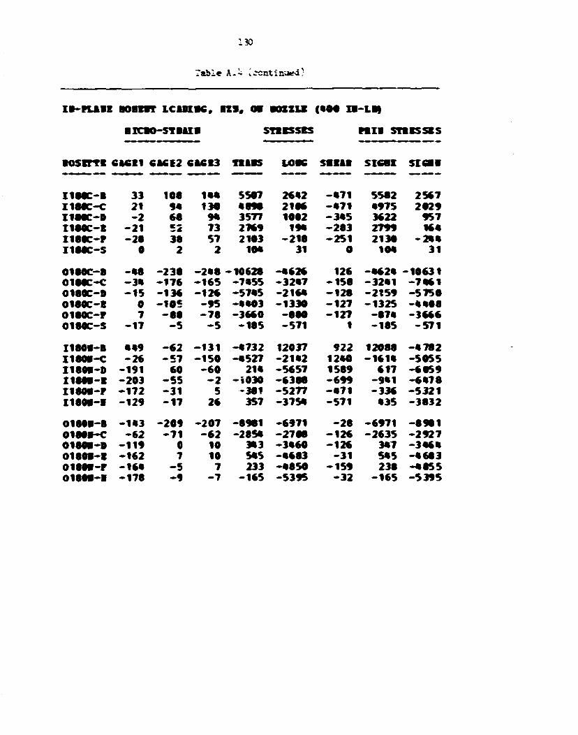
130
I 8 - H A 1 E BOBEBT LCADI8C, l » ( 0 8 BOZZU | 8 0 0 IB-LB)
BICBO-STBUB STBESSES M i l STB8SSBS
•OSITT8 C1CE1 CBCE2 CB8E3 f l i B S LOBS SBE1I SICBt SIOEB
I188C-B 33 108 188 5507 2882 - • 7 1 5582 2567 I188C-C 21 98 138 8898 2186 - • 7 1 •975 2829 I188C-D - 2 88 98 3577 1862 - 3 8 5 3622 957 I180C-B - 2 1 52 73 2789 19* - 2 8 3 2799 168 I188C-P - 2 8 38 57 2183 -218 - 2 5 1 2138 - 2 8 8 X188C-S 8 2 2 10* 31 0 10« 31
0180C-B - • 8 -238 - 2 8 8 -10628 - • 6 2 6 126 - • 4 2 * -16631 0188C-C - 3 8 -176 - 1 6 5 -7855 -32«7 - 1 5 8 -3281 - 7 8 6 1 O180C-D - 1 5 -136 - 1 2 8 -5785 -2168 - 1 2 8 -2159 - 5 7 5 0 O180C-B 0 -105 - 9 5 - • • 8 3 -1330 - 1 2 7 -1325 - • • 0 8 0180C-P 7 - 8 8 - 7 8 -3660 -880 -127 -878 -3666 O180C-S - 1 7 - 5 - 5 -105 - 5 7 1 1 -185 - 5 7 1
I1801-B •«9 - 6 2 - 1 3 1 -8732 12037 922 12088 - 8 7 8 2 I180B-C - 2 8 - 5 7 - 1 5 0 - •527 -21«2 1280 -1618 -5055 I180B-D -191 60 - 6 0 2 1 * -5657 1589 617 -6859 I180B-B -203 - 5 5 - 2 -1030 -6388 - 6 9 9 -9«1 -8878 I180B-P - 1 7 2 - 3 1 5 -381 -5277 - • 7 1 -336 - 5 3 2 1 I180B-B -129 - 1 7 26 357 -3758 - 5 7 1 •35 -3832
0188B-B - 1 « -209 -207 -6981 -6971 - 2 8 -6971 - 8 9 8 1 0180B-C - 8 2 - 7 1 - 6 2 -2858 -2708 - 1 2 6 -2635 -2927 0180B-B -119 0 10 383 -3860 -126 3*7 -3«6« 0180B-E -182 7 10 585 -8683 - 3 1 585 - • 6 8 3 0188B-P -16» - 5 7 233 -8850 - 1 5 9 236 -8855 O180B-B -178 - 9 - 7 -165 -5395 - 3 2 - 1 6 5 -5395

IB-KABE BOBEBT L C W I K , 1 1 1 , OB BOZZU | 0 0 0 IB~LB)
BICSO-STBIIB STBCSSBS FBII STB ESSES
BOSBTTB 616E1 C1CE2 CBCE3 TB1BS LOBS SBEIB SIOBX SIC9K
I270C-C - 2 -172 153 -007 -107 -0322 0027 -0620 I270C-B - 5 -103 127 - 3 5 1 -2«2 -359B 3290 -3007 I270C-E - 5 - 120 100 - 3 5 1 -2«2 -3003 2707 -3379 I270C-F - 5 - 100 9 1 -19« -19% -2502 23*8 -2737 I270C-B - 2 - 6 7 65 - 3 8 - 7 5 -1700 1691 -1005 I270C-J - 2 - 3 0 36 - « 2 - 7 7 - 9 « f 925 -1000 I270C-B - 2 - I t 17 - • 3 - 0 0 - O r j 015 - 5 3 0 I270C-L 0 - • 0 - 0 0 - 2 2 • 5 7 11 - 1 2 1 I270C-B - 2 -3 - 5 - 3 9 - 7 5 96 00 - 1 5 5 I270C-B - 2 - 2 - 2 - 9 0 - 9 0 - 1 - 9 7 - 9 9 I270C-B* 150 - 2 0 - 223 0602 - 3 3 0603 - 2 2 3 I270C-T - 2 - 7 - 2 -190 - 1 3 0 - 6 0 - 9 2 - 2 3 6
O270C-B 2 - 7 7 109 700 267 -2070 2960 -1993 O270C-C - 1 - 7 9 99 009 110 -2379 2660 - 2 1 0 1 O270C-B 7 - 6 0 73 205 203 - 1 7 7 2 2056 -1000 O270C-E % - • 3 50 2 3 * 197 -1299 1515 -1003 O270C-E 0 - 2 0 30 101 101 - 380 1069 - 7 0 7 O270C-B 2 - 0 14 120 91 - 2 8 0 390 - 1 7 5 O270C-J 2 6 - 3 7 1 73 125 197 - 5 2 O270C-B - 1 11 - 1 0 31 - 7 206 290 - 2 7 5 O270C-1 - 1 11 - 1 0 25 - 9 200 292 - 2 7 7 O270C-B 0 5 - 5 - 1 2 - 1 0 120 115 - 1 0 0 O270C-B 0 0 0 - 1 3 - 1 6 - 1 - 1 3 - 1 6 O270C-B 0 0 0 - 1 1 - 1 3 0 - 1 1 - 1 3 O270C-T 0 0 0 - 1 « - 1 0 0 - 1 0 - 1 9
I270B-B - 2 6 -162 165 75 - 7 7 1 -0356 0029 - • 7 2 5 I270B-C - 3 - 1 2 12 - 1 - 7 6 -317 201 - 3 5 0 I270B-B 0 19 - 2 6 - 160 - 5 3 600 500 - 7 1 3 I270B-B - 3 10 - 1 9 -210 - 1 0 0 382 209 - 5 5 9 I270B-P - 1 2 - 7 -104 - 7 0 120 39 - 217
O270B-B I t 70 - 0 3 665 6 3 0 1509 2196 - 9 0 2 O270B-C 2 52 - 0 0 260 151 1232 1039 -1020 02701-0 * 21 - 1 7 0 * 155 500 629 - 3 9 0 O270B-E • 7 - 5 33 101 157 253 - 7 9 O270B-P 7 • - 3 19 202 07 200 - 2 3 O270T-O 7 5 0 90 235 60 259 6 6 O270B-f 7 7 - 3 79 223 127 297 5 O270B-E « « - 3 27 132 03 106 - 2 7 O270B-B - 1 2 - 1 27 - 1 0 32 05 - 3 1
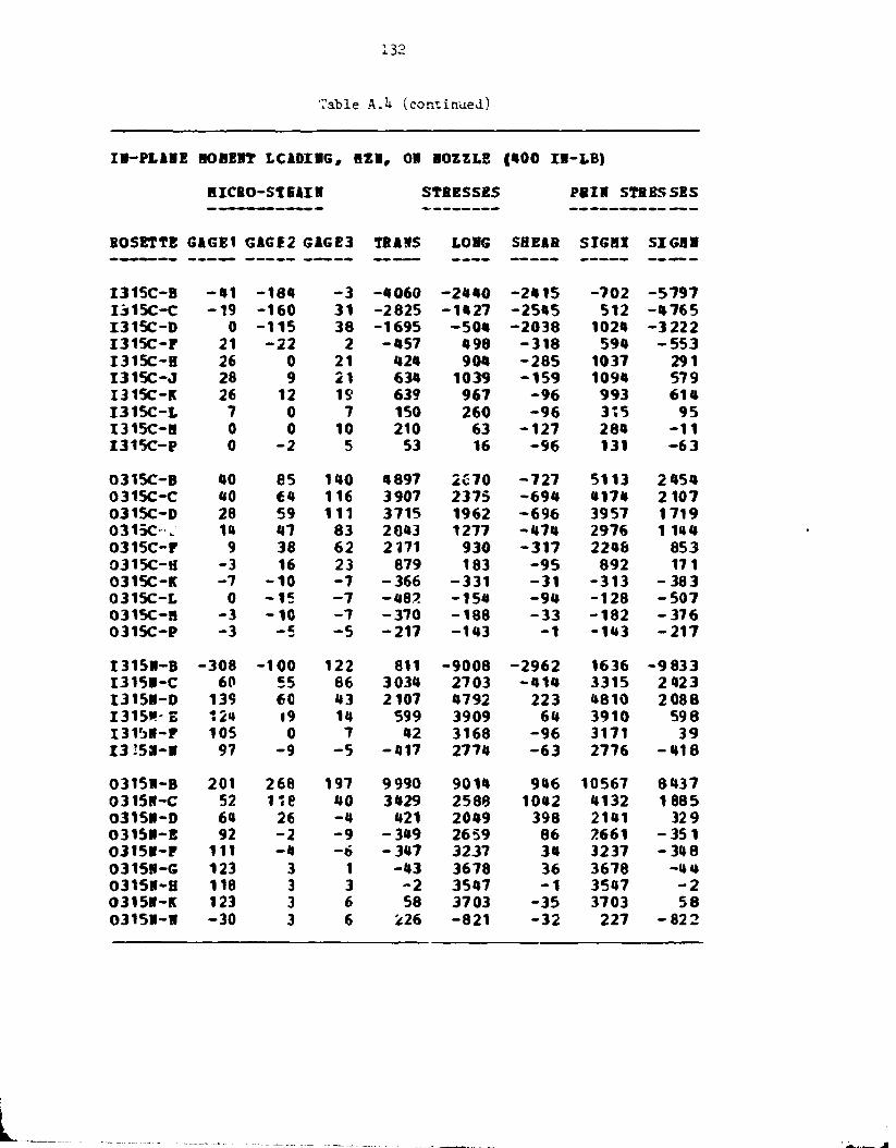
132
Table A.U (continued)
IH-PLAHE BOH EST LCADIBG, BZH, OH BOZZLE | 4 0 0 IH-LB)
BICBO-STEAIH STRESSES PBIR STRESSES
BOSETTE GAGE1 GAGE2 GAGE3 TRAMS LOBG SHEAR SIGH! SIGBB
I315C-B - 4 1 -184 - 3 -4060 -2440 -2415 -702 -5797 I315C-C - 1 9 -160 31 -2825 -1427 -2545 512 -4765 I315C-D 0 -115 38 -1695 -504 -2038 1024 - 3 222 I315C-P 21 - 2 2 2 -457 498 -318 594 - 5 5 3 I315C-B 26 0 21 424 904 -285 1037 291 I315C-J 28 9 21 634 1039 -159 1094 579 I315C-K 26 12 IS 639 967 - 9 6 993 614 I 3 1 5 C - I 7 0 7 150 260 - 9 6 315 95 I315C-B 0 0 10 210 63 -127 284 - 1 1 I315C-P 0 - 2 5 53 16 - 9 6 131 - 6 3
0315C-B HO es 140 4897 2670 -727 5113 2 454 0315C-C ao 64 116 3907 2375 -694 4174 2107 0315C-D 28 59 111 3715 1962 -696 3957 1719 0315O . 14 47 83 2843 1277 -474 2976 1 144 0315C-r 9 38 62 2171 930 -317 2248 853 0315C-H - 3 16 23 879 183 - 9 5 892 171 0315C-K - 7 - 1 0 - 7 -366 -331 - 3 1 -313 - 3 8 3 0315C-L 0 - 1 5 - 7 -482 -154 - 9 4 -128 - 5 0 7 0315C-B - 3 - 1 0 - 7 -370 -188 - 3 3 -182 - 3 7 6 0315C-P - 3 — 5 - 5 -217 -143 - 1 -143 - 2 1 7
I315B-B -308 -100 122 811 -9008 -2962 1636 -9833 I315H-C 60 55 86 3034 2703 -414 3315 2 423 I315H-D 139 60 43 2107 4792 223 4810 2088 1315*-S 12* 19 14 599 3909 64 3910 598 I315H-F 105 0 7 42 3168 - 9 6 3171 39 I 3 25S-H 97 - 9 - 5 -417 2774 - 6 3 2776 - 4 1 8
0315H-B 201 268 197 9990 9014 946 10567 8437 0315H-C 52 118 40 3429 2588 1042 4132 1885 0315H-D 64 26 - 4 421 2049 398 2141 329 0315H-E 92 - 2 - 9 -349 2659 86 2661 - 3 5 1 0315H-F 111 -ft - 6 -347 3237 34 3237 - 3 4 8 0315H-G 123 3 1 - 4 3 3678 36 3678 -4 4 0315H-H 118 3 3 - 2 3547 - 1 3547 - 2 0315R-K 123 3 6 58 3703 - 3 5 3703 58 0315R-H - 3 0 3 6 226 -821 - 3 2 227 - 8 2 2

133
Table A. 5- In-plane force, F.
IM-PLAMB FO'CE LOiCIHG, FIR, OH MOZZLB (80 LB)
HICRO-STFAIM STRESSES PRIM STRESSES
ROSETTE GAGF1 GAGI2 GAGE3 TRAMS LOMG SHEAR SIG!1X SIGHP
I - O - C - C 86 265 286 12018 6184 - 2 86 12032 6170 I - O - C - D 17 196 229 9316 3297 - 4 45 9349 3265 T -O-C-E - 3 3 150 174 7169 1151 - 3 1 7 7186 1134 I - O - C - F - 5 7 12ft 1ft1 5884 50 - 2 2 2 5892 42 I -O -C- H - 8 8 76 7« 3402 - 1 6 2 4 31 3403 - 1 6 2 4 I - O - C - J - 7 1 57 50 2«42 - 1 4 1 1 95 2444 - 1 4 1 4 I - O - C - K -as ftl 46 199ft - 7 5 9 - 9 6 1997 - 7 6 2 I - O - C L * -13ft 26 3ft 1462 - 3 5 7 4 - 9 5 1464 - 3 5 7 6 i-o-c-n - 7 19 22 903 59 - 3 2 904 58 I - O - C - P - 5 12 10 483 5 32 485 3 I - O - C - S 0 7 c 262 84 3* 269 77
0 -O-C-E - 1 6 8 - 6 1 1 - 6 4 0 -27311 - 1 3 2 3 2 376 - 1 3 2 2 2 - 2 7 3 2 1 o-o-c-c - 1 0 2 - 4 0 0 - 4 2 2 -17945 - 3 4 3 3 285 - 8 4 2 4 - 1 7 9 5 4 O-O-C-D - ^ 2 - 3 0 8 - 3 2 4 -1383^ - 5 7 0 0 219 - 5 6 9 5 - 1 3 8 4 1 0 - O - C - E - 2 - 2 5 8 - 2 5 5 -11277 - 3 4 3 8 - 3 6 - 3 4 3 8 - 1 1 2 7 7 O-O-C-F 8 - 2 1 1 - 196 -8950 - 2 4 5 4 - 1 8 9 - 2 4 4 8 - 8 9 5 6 0 -O-C-H 29 - 1 1 1 - 1 1 9 -5063 - 6 5 0 94 - 6 4 8 - 5 0 6 5 0 - O - C - J 20 - 5 9 - 5 1 -2445 - 1 4 1 - 1 0 0 - 1 3 6 - 2 4 4 9 0-O-C-K 3 - 3 5 - 3 3 -1488 - 3 5 6 - 3 2 - 3 5 5 - 1 4 8 9 O-O-C-L - 9 - 2 1 - 2 1 -906 - 5 3 4 1 - 5 3 4 - 9 0 6 o-o-c-n - 7 - 1 6 - 1 6 - 7 0 0 - 4 0 5 1 - 4 0 5 - 7 0 0 0 - O - C - P -ft - 9 - 9 - 3 9 2 - 2 4 1 - 2 - 2 4 1 - 3 9 2 0 -O-C-S - 2 - 7 - 7 - 2 8 8 - 1 3 2 0 - 1 1 2 - 2 8 8
I - O - M - B 1188 - 1 1 5 - 2 0 6 -8346 33146 1212 33181 - 3 3 8 1 I -O-W-C -1*13 - 2 7 3 - 2 6 8 -11720 - 8 1 0 3 - 6 3 - 8 1 0 2 - 1 1 7 2 1 I - O - M - D -ft62 - 2 0 6 - 1 8 9 -8174 - 1 6 3 0 9 - 2 2 4 - 8 1 6 8 - 1 6 3 1 5 I - O - N - E - 0 3 1 - 6 7 - 6 9 - 2 5 2 2 - 1 3 6 8 0 30 - 2 5 2 1 -136e i I - O - N - F - 3 5 2 - 9 - 1 7 - 1 8 3 - 1 0 6 1 1 98 - 1 8 2 - 1 0 6 1 1 I -O-N-W 19 -2ft 22 - 5 8 566 - 6 0 7 937 - 4 2 8
O-C-N-B -H55 - 6 7 8 - 6 7 8 -29283 - 2 2 4 2 9 1 - 2 2 4 2 9 - 2 9 2 8 3 0 -O-H-C - 1 3 9 - 1 9 6 - 1 9 6 -8464 - 6 7 1 8 2 - 6 7 1 8 - 8 4 6 4 0 -O-H-D - 2 1 5 - 1 1 - 2 1 - 4 7 3 - 6 5 9 5 130 - 4 7 0 - 6 5 9 7 0 - O - J - E - 3 0 3 38 5 1285 - 8 6 99 444 1304 - 8 7 1 9 0 - O - N - P - 3 « 1 ?€ - 2 1122 - 9 8 8 4 503 1145 -990*7 O-C-M-H -3ft6 - 9 - 9 - 2 4 - 1 0 3 7 5 - 1 - 2 4 - 1 0 3 7 5 O-O-K-K - 3 0 0 - 7 - 9 - 2 5 - 9 0 1 4 33 - 2 5 - 9 0 1 5 O-O-M-M* - 1 9 6 - 1 6 1147 25060 1631 - 1 5 4 9 2 32768 - 6 077

Table A. 5 (continued)
TW-PLAWfc FORCE LOHCTRG, FTR, 0!l MOZZLE (80 LB)
MCRO-STFUR STRESSES PRIH STRESSES
ftOSETTB GIGF1 GAGF2 GAGE3 TR\HS LONG SHEAR SIGffl SIGH*
I - 9 0 C - B - 2 6 - 2 4 2 2 0 1 -86ft - 1 0 4 8 - 5 9 0 1 4946 - 6 8 5 8 I - 9 0 C - C * -2ft - 3 6 4 0 - 7 9 7 0 - 3 1 0 7 - 4 8 4 8 - 1 1 5 - 1 0 9 6 2 T -90C-D - 1 7 - 3 0 « 3 2 3 4 4 2 - 3 6 9 - 8 3 5 7 8404 - 8 3 3 1 I -OAC-E - 5 - 2 5 6 2 7 5 4 2 8 - 1 2 - 7 0 8 1 729 3 - 6 8 7 7 I - 9 0 C - F - 1 2 - 1 8 0 2 3 0 1110 - 2 4 - 5 4 6 1 6033 - 4 9 4 7 I - 9 0 C - P * 0 0 C 3 3 0 4 3
O-90C-B 3ft - 8 7 12« 7 7 1 1248 - 2 8 0 6 3826 - 1 8 0 7 O-90C-C 2 2 - 2 5 8 2 0 7 - 1156 3 0 9 - 6 1 9 5 5815 - 6 6 6 2 0 - 9 0 C - D 15 - 1 9 2 15C - 9 2 8 165 - 4 5 5 8 4210 - 4 9 7 2 O-90C-E 10 - 1 3 2 1 0 7 - 5 6 9 129 - 3 1 9 2 2991 - 3 4 3 1 0 - 9 0 C - F 5 - 8 ? 83 - 4 3 140 - 2 2 4 4 2294 - 2 1 9 7 O-90C-R 1 1 6 1 5 * 63 - 7 8 2 0 0 18
I - 9 0 1 - B -22ft - 2 6 7 3 3 2 1668 -6214 - 7 9 8 1 6627 - 1 1 1 7 4 I - 9 0 M - C 6ft 57 10 1399 2354 6 3 5 2671 1082 I - 9 0 H - D 9 f 9 1 - 6 0 5 8 0 3049 2004 4168 - 5 3 9 I - 9 0 K - E 7 0 48 - 6 0 - 3 3 4 1986 1431 2668 - 1 0 1 7 I - 9 0 K - F ft8 ftl - t t5 -15a 1389 1144 1997 - 7 6 2 I -90H-1 I -5ft - 2 1 - 3 3 - 1 1 1 6 - 1 9 6 3 1 5 9 - 1 0 3 7 - 1 9 9 2
O-90S-B - 1 6 79 - 1 3 7 - 1 2 7 0 - 8 6 2 2877 1818 - 3 9 5 0 O-90H-C 3 62 - 7 5 - 2 9 * - 5 1832 1688 - 1 9 8 8 O-90W-D 1 c - 2 72 39 93 1 5 0 - 3 9 O-90R-? - 6 - 2 1 15 - 1 2 2 - 2 1 2 - 4 7 4 3 0 9 - 6 4 2 0-90W-F - 6 - 1 3 20 142 - 1 4 4 - 4 39 4 6 1 - 4 6 3 O-90W-R - 2 - 1 8 13 - 1 2 2 - 8 7 - 4 1 0 3 0 6 - 5 1 5

135
Table A.t> (continued)
IN-PLANE FORCE LOAtTNG, FXN, ON NOZZLE J80 LB)
HICRO-STSAIN STRESSES PRIN STRESSES
ROSETTE GAGE1 GAGF.2 GAGES TRANS LORG SHEAR SIGftX SIGfIN
I 180C-B - 7 5 - 2 5 2 - 3 1 6 - 1 2 * 0 9 - 5 9 8 7 849 - 5 8 7 7 - 1 2 5 1 9 I 1 8 0 C - C - 5 2 - 2 3 1 - 2 8 3 - 1 1 2 4 ? - 4 9 2 9 692 - 4 8 5 4 - 1 1 3 1 7 T180C-0 9 - 1 7 0 - 2 0 9 - 8 3 0 2 - 2 2 0 7 503 - 2 1 6 5 - 8 3 4 9 I 1 8 0 C - E 50 - 1 2 7 - 1 6 3 -642<> - 4 4 2 471 - 4 0 5 - 6 4 6 6 I 1 8 0 C - F 66 - 9 4 - 1 2 7 - 4 9 4 * 498 440 533 - 4 9 8 0 I180C-S 2 _ c - 5 - 2 0 7 11 0 11 - 2 0 7
O180C-B 115 5ao 526 23297 10433 192 23300 10430 O180C-C 81 ao e 38f 17275 7702 251 17282 7695 O180C-D U4 305 300 13139 5311 129 13340 5309 O180C-E 8 241 229 1019* 3293 222 10203 3286 01 POOF - 1 7 195 176 8173 1955 253 8134 1945 O180C-S - 3 2 0 0 38 - 9 5 1 1 38 - 9 5 1
I 1 8 0 N - B - 1 0 3 9 120 311 10607 - 2 7 9 8 2 - 2 5 3 7 1077 3 - 2 8 1 » 8 T180N-C 51 12C 344 10137 4561 - 2 9 8 5 11434 3265 11 SON-0 »32 - 1 5 2 129 - 9 7 0 12676 - 3 7 4 7 13637 - 1 9 3 1 I180N-E 451 113 - 4 1890 14105 1559 14301 1694 I 1 8 0 N - F 380 57 - 9 620 11578 880 11649 550 I180N-N 10ft 20 - 3 3 - 4 3 8 4179 702 4283 - 5 4 2
O180N-B 328 500 468 209 25 16124 422 20961 16087 O180N-C 128 171 138 6655 5850 4 4 4 6851 5653 0180N-D 250 c - 3 1 - 8 4 7 7 239 475 7267 - 8 7 5 O180N-B 345 - 1 2 - 3 1 - 1 3 1 8 9951 254 9956 - 1 3 2 4 0180N-F 347 m - 2 6 - 6 4 2 10223 539 10250 - 6 6 9 0180N-N 202 5 0 - 115 6032 63 6032 - 1 1 5

136
Table A.5 (continued)
I I -PL 1KB FORCE LOICI1G, F l l , OR ROZZLE (80 LB)
HICRO-STEAIR STRESSES PRIR STRESSES
ROSETTE GIGF1 GAGE2 GAGE3 TR1RS LORG SHEAR SIG1I SIGHR
I 2 7 0 C - C - » 378 - 3 6 1 37* 5 9 8 * 9 100*0 - 9 6 6 1 I 2 7 0 C - D - 1 316 - 3 0 2 321 61 8233 8a2a - 8 0 * 3 I 2 7 0 C - B 6 276 - 2 5 6 »21 306 7005 7 * * 9 - 6 7 2 2 I 2 7 0 C - F t 223 - 2 2 C 56 126 5910 6001 - 5 8 1 9 T270C-B - 3 1*9 - 1 5 1 - 3 6 - 1 1 3 4002 3928 - * 077 I 2 7 0 C - J 1 80 - 8 7 - 1 6 6 - 1 3 2226 2138 - 2 3 1 7 I270C-K - * 39 - • 5 - 1 1 3 - 1 5 6 1115 981 - 1 2 5 0 I 2 7 0 C - L - a C - * 30 - 1 0 9 120 99 - 1 7 8 I270C-H - 1 « •• 6 60 - 1 0 - 1 2 3 153 - 1 0 3 I 2 7 0 C - P - 3 - 2 6 79 - 5 6 - 1 0 2 133 - 1 1 1 T270C-R 11 4 * 2 92 361 3 361 82 I 2 7 0 C - T 0 - 3 2 - 3 2 - 1 » - 6 » * 2 - 8 7
O270C-B 1 205 - 2 » 6 -90S - 2 a 3 6012 5 * * 7 - 6 5 9 5 0270C-C 5 195 - 2 2 3 - 6 0 6 - 1 9 5572 5267 - 5 8 9 2 O270C-O - 9 150 - 1 6 6 - 3 3 1 - 3 6 * 4206 3858 - * 5 5 « O270C-E - * 112 - 1 2 0 - 1 7 7 - 1 7 6 3101 292a - 3 2 7 8 0270C-F - 2 79 - 8 5 - 1 2 7 - 9 0 2 1 8 * 2075 - 2 2 9 3 O270C-H 1 27 - 3 0 - 7 5 0 759 722 - 7 9 7 O270C-J 3 - 9 10 3» 105 - 2 5 1 322 - 1 8 * O270C-R 5 - 1 8 2 * 125 200 - 5 7 0 7 3 * - a 0 9 O270C-L 3 - 2 1 24 83 116 - 6 0 0 699 - 5 0 1 0270C-B 3 - 9 13 7a 115 - 2 8 8 383 - 1 9 a O270C-P 1 3 3 133 66 1 133 66 O270C-R 1 1 1 23 29 0 29 23 O270C-T* 1 - 2 0 - 3 9 20 - 2 3 28 - a 6
I 2 7 0 S - B 31 358 - 3 7 0 -29a 8U5 9700 9993 - 9 f t * 1 I270! f -C 0 2 106 33 0 106 33 I270H-D 2 - 7 a 9 1 366 183 - 2 1 9 a 2 * 7 1 - 1 9 2 2 I 2 7 0 R - E 7 - 5 2 76 518 372 - 1 7 1 8 216a - 1 2 7 * I270W-F 11 - 3 a 50 356 a a i - 1 1 1 7 1516 - 7 1 9
O270H-B - 2 8 - 1 3 2 74 - 1 2 5 6 - 1 2 1 0 - 2 7 a 5 1511 - 3 9 7 8 0270H-C - 7 - 9 5 69 - 5 5 3 - 3 6 9 - 2 1 8 0 1721 - 2 6 a 3 O270R-D - a - 1 8 13 -126 - 1 5 9 - a i a 271 - 5 5 6 02701-E - 9 15 - 1 6 - 1 7 - 2 7 2 * 1 3 288 - 5 7 7 O270W-F - 6 22 - 2 3 - 2 - 1 8 6 599 512 - 7 0 1 0270H-G - 7 19 - 2 3 -8tt - 2 2 9 5 7 0 U18 - 7 3 1 O270W-H - 9 17 - 2 3 -118 - 2 9 7 5 39 339 - 7 5 0 O270H-K - 1 25 - 1 8 13<» 1 57a 6U8 - 5 0 8 O270W-R 1 22 - 2 3 - 1 0 31 601 611 - 5 9 0

137
Table A.5 (continued)
IR-PLftRB FORCE LOAEIBG, P I 1 , OR ROZZLE (80 LB)
RICKO-STBAIR STRESSES PRIR STRESSES
ROSETTE G&GE1 GAGE2 G1GE3 TR1RS LOHG SBEAR SIGfIX SIGBH
I 315C-B 93 • 25 - • 9154 55«8 5722 13350 1352 I 3 1 5 C - C • 3 373 - 8 3 6326 3200 6076 11037 - 1 5 1 1 I 3 1 5 C - D - 3 266 - 9 7 3717 1036 «8«7 7«05 - 2 6 5 2 I 3 1 5 C - F - 5 * «e - 9 925 - 1 3 5 3 763 1157 - 1 5 8 5 I 3 1 5 C - H - € • i - 5 6 - 1 1 5 5 - 2 2 6 1 762 - 7 6 7 - 2 6 * 9 I 3 1 5 C - O - 7 3 - 2 6 - 5 7 - 1 7 2 6 - 2 7 1 8 «1« - 1 5 7 6 - 2 8 6 8 I315C-R - * 9 - 3 0 - • 7 - 1 6 M - 2 2 6 0 223 - 1 5 6 9 - 2 3 3 2 I 3 1 5 C - L - 1 9 2 - 2 « - • 5 3 - 7 1 1 3«8 - 2 1 1 - 9 5 3 I 3 1 5 C - H - 5 - 1 - 2 1 - • 8 8 - 2 8 9 27« - 9 8 - 6 8 0 I 3 1 5 C - P 0 0 - 1 2 - 2 6 2 - 7 5 157 1« - 3 5 1
0315C-B - 9 * - 1 9 6 - 3 3 « - 1 1 S O - 6 2 8 6 18 3« - 5 7 0 9 - 1 2 1 2 1 0315C-C - 8 9 - 1 * 2 - 2 7 » - 9 0 » 7 - 5 3 9 9 1766 - « 6 8 « - 9 7 6 2 0315C-D - 6 3 - 1 2 5 - 2 5 8 - 8 3 5 5 - • • 0 9 1771 - 3 7 3 1 - 9 0 3 3 0315C-E - 3 3 - 9 7 - 1 8 9 - 6 2 » 9 - 2 8 6 1 1233 - 2 « 6 0 - 6 6 5 0 0315C-P - 1 8 - 7 7 - 1 « 0 - • 7 * 3 - 1 9 7 5 831 - 1 7 » « - • 9 7 * 0315C-H 12 - 3 8 - 5 « - 2 0 2 9 - 2 3 6 221 - 2 0 9 - 2 0 5 5 0315C-K 15 26 17 938 722 125 995 665 0315C-L 3 19 17 801 329 31 803 327 0315C-H 0 19 12 693 218 97 712 199 0315C-P 5 8 5 276 238 3* 296 218
I31SR-B 715 227 - 2 7 3 - 1 7 8 « 20923 6661 22733 - 3 5 9 * I 3 1 5 R - C - 1 3 « - 1 5 5 - 1 7 5 - 7 1 0 6 - 6 1 5 0 255 - 6 0 8 6 - 7 1 7 0 I315R-D - 3 1 3 - 1 6 7 - 6 9 - • 8 5 8 - 1 0 8 5 8 - 1 3 0 7 - • 5 3 6 - 1 1 1 3 0 I 3 1 5 1 - E - 2 7 3 - 7 2 - 7 - 1 * 3 3 - 8 6 0 9 - 8 6 0 - 1 3 3 2 - 8 7 1 1 I 3 1 5 R - F - 2 2 5 - 2 » 10 - 6 7 - 6 7 6 5 - • • 6 - 3 7 - 6 7 9 5 I315R-R - 1 0 6 - 7 28 584 - 3 0 0 3 - • 7 1 6ft5 - 3 0 6 6
0315R-B - • 5 6 - 6 1 2 - • 8 6 - 2 3 6 2 3 - 2 0 7 6 6 - 1 6 7 2 - 1 9 9 9 6 - 2 « 3 9 3 0315R-C - 1 0 * - 2 5 8 - 1 1 6 - 8 1 0 8 - 5 6 2 » - 1 8 9 * - • 6 0 1 - 9 1 3 1 0315R-D - 1 3 0 - • 2 - e - 9 6 0 - • 1 7 6 - 4 6 3 - 8 9 » - • 2 « 1 0315R-E - 1 8 8 28 2 870 - 5 385 3«9 890 - 5 » 0 « 0315R-P - 2 3 1 28 - 1 0 6U3 - 6 7 3 1 • 99 677 - 6 7 6 U 0315R-G - 2 « 0 13 - 2 2 91 - 7 * 5 8 • 66 120 - 7 6 8 7 0315R-H -2U0 10 - 2 6 - 1 1 - 7 2 0 5 533 28 -72Uft 031<R-K - 2 1 9 18 - 2 9 7 - 6 5 6 * 6 28 67 - 6 6 2 3 0315R-R - 5 3 *6 - 2 6 - 1 7 5 - 1 6 3 » 563 17 - 1 8 2 6

138
Table A.6. Axial force, FVK, on nozzle
AXIAL FCRCB LOADIIG, FT I , CS BOZZLB (400 LB)
HICBO-STBAIB STBBSSES PRIP STBBSSBS
BOSETTE GIGE1 GAGE2 GAGF3 TBASS LOiG SHEAR SIGHX SIGHB
I -O -C -C - 1 5 - 5 0 - 1 1 5 -3616 - 1 5 2 3 858 - 1 2 1 6 - 3 9 2 3 I - O - C - 0 2 * - 5 8 - 1 1 7 - 3 8 6 5 - 4 52 794 - 2 7 6 - 4 0 4 1 I - O - C - B • 3 - 6 0 - 1 1 0 - 3 7 8 2 148 667 258 - 3 8 9 2 I - O - C - F 50 - 6 7 - 1 1 0 - 3 9 4 3 311 573 387 - 4 019 I - O - C - B 54 - 9 3 - 7 2 - 3 6 9 0 526 - 2 8 6 546 - 3 710 I - O - C - J • 0 - e i - 6 2 - 3206 243 - 2 5 3 261 - 3 2 2 5 I - O - C - I 28 - 5 3 - 7 4 - 2 8 2 7 - 2 289 28 - 2 8 5 7 I - O - C - L * 69 - 4 1 - 5 8 -2245 1409 223 1423 - 2 2 5 8 I - O - C - H 9 - 3 6 - 4 6 - 1 8 0 8 - 2 6 8 126 - 2 5 8 - 1 8 1 8 I - O - C - P 2 - 2 7 - 2 9 - 1 2 3 2 - 3 1 1 34 - 3 1 0 - 1 2 3 3 I - O - C - S 2 - 1 5 - 1 4 - 6 3 2 - 1 3 8 - 1 4 - 1 3 7 - 6 3 3
O-O-C-B 52 2C9 194 8792 *193 192 8800 4 185 O-O-C-C 26 163 142 6676 2778 284 6696 2757 O-O-C-D 1 * 137 123 5702 2124 191 5712 2114 O-O-C-E - 3 125 106 5086 1441 257 5104 1423 0 - O - C - F - 1 113 92 4518 13.19 284 4543 1314 O-O-C-B - 3 78 75 3370 926 32 3371 926 O-O-C-J 2 66 54 2644 854 160 2659 840 O-O-C-K 7 52 47 2170 856 63 2173 853 O-O-C-L 7 42 38 1755 730 63 1759 726 O-O-C-B « 35 31 1444 567 63 1449 563 O-O-C-P 0 26 23 1086 317 32 1087 316 O-O-C-S - 5 14 14 621 33 0 621 33
I - O - i - B - 3 8 6 103 31 3360 - 1 0 5 6 4 957 3425 - 1 0 6 2 9 I - O - K - C 7 117 105 4879 1670 159 4887 1662 I - O - l - D 98 77 81 3362 3945 - 6 3 3951 3355 I - O - B - E 81 33 36 1432 2864 - 3 0 2864 1432 I - O - l - F 57 17 17 666 1918 - 2 1918 666 I - O - I - B 62 7 - 3 24 1867 128 1876 15
O-O-a-B 21 168 187 7785 2971 - 2 5 3 7799 2957 O - O - i - C - 6 0 26 45 1615 - 1 3 0 2 - 2 5 4 1637 - 1 3 2 4 O - O - I - D - 2 » -26 - 1 4 - 8 6 8 - 9 7 9 - 1 5 9 - 7 5 5 - 1 0 9 2 O - O - i - B 14 - 2 9 - 2 1 - 1116 85 - 9 6 93 - 1 1 2 3 O-O- l l -F 31 - 2 4 - 1 4 - 8 7 5 654 - 1 2 5 665 - 8 8 5 O - O - i - B 42 - 1 7 - 1 0 - 6 2 5 1087 - 9 4 1092 - 6 3 1 O - O - I - K 54 - 1 4 - 7 - 5 3 2 1466 - 9 5 1471 - 5 3 7 O - O - l - B 57 0 77 1632 2191 - 1 0 3 3 2982 841

139
Table
AXIAL POBCE LOADIBG, PYB,
BICBO-SIBAIB
BOSRTE GAGE1 GAGI2 GAGE3
I-90C-B - 1 7 - ? 0 - 5 0 I -90C-C* - 1 0 - 4 1 0 I-90C-D 10 - 2 4 - 3 3 I -90C-E 24 - 1 2 - 1 9 I -90C-P 33 14 - 1 0 I-90C-B 12 - 2 - 1 0
0-90C-B 35 121 142 O-90C-C 33 119 116 0-90C-D 29 57 88 O-90C-E 1* 62 57 0-90C-P 5 46 43 O-90C-B - 9 - I B - 1 4
I -90B-B - 2 9 6 76 - 1 0 I -90B-C 59 79 69 I -90B-D 109 33 45 I -90B-E 83 - 1 2 5 I -90B-P» - 7 4 - 5 3 28 I -90B-B - • 3 - 3 1 - 3 6
O-90B-B 81 188 206 O-90B-C - 1 2 43 64 0-90B-D 19 - 2 12 0-90B-E 31 - 2 10 O-90B-P • 5 17 12 0 - 9 0 1 - B 29 - 5 7
CB BOZZLE (400 LB) STBESSES PBIB STBESSES
TBABS LOBG SBEAB SIGHX SIGHB
- 2 1 9 0 - 1 1 5 9 0 - 1 1 5 9 - 2 1 9 0 - 8 8 3 - 5 5 2 - 5 4 2 - 1 5 1 - 1 2 8 4
- 1 2 7 2 - 9 5 127 - 8 1 - 1 2 8 6 - 7 1 0 505 96 512 - 7 1 7
68 1025 319 1122 - 2 8 - 2 7 6 276 96 292 - 2 9 2
5731 2777 - 2 8 6 5759 2749 5129 2539 32 5129 2538 4041 2070 126 40«9 2062 2595 1209 64 2597 1206 1979 738 63 1982 735 - 6 0 4 - 4 6 2 - 3 - 4 6 2 - 6 0 4
1791 - 8 3 4 3 1145 1919 - 8 4 7 0 3178 2735 128 3212 2701 1608 3767 - 1 6 0 3779 1596 - 2 5 0 2423 - 2 2 3 2442 - 2 6 8 - 4 5 8 - 2 3 7 2 - 1 0 7 9 28 - 2 8 5 7
- 1 4 3 2 - 1 7 2 5 64 - 1 4 1 9 - 1 7 3 8
8570 4995 - 2 5 3 8588 4 977 2364 356 - 2 8 5 2403 316
192 631 - 1 9 0 702 121 126 968 - 1 5 8 997 98 580 1530 64 1534 576
25 865 - 1 5 8 893 - 3

ihG
Table A.6 (continued)
IXI iL POBCE LOAOIIG. PYI, CI BOZZLE («00 LB)
HICBO-STBAI* STRESSES PBII STB ESSES
BOSETTE G1GE1 GiGE2 GBGE3 TBilS LOBG SHEAB SIGHI SIGHI
I 180C-B - 7 - 7 6 - 3 1 - 2 3 3 5 - 9 2 0 - 5 9 8 - 7 0 1 - 2 5 5 4 I 1 8 0 C - C 7 - 1 0 4 - 5 0 - 3 3 8 8 - 8 1 2 - 7 2 4 - 6 2 2 - 3 5 7 7 I 1 8 0 C - 0 33 - 1 0 2 - 6 2 - 3 6 2 4 - 1 1 0 - 5 3 4 - 3 0 - 3 7 0 3 I 1 8 0 C - E 52 - 1 0 2 - 6 9 - 3 8 0 1 407 - 4 3 9 452 - 3 8 4 6 I 1 8 0 C - P 52 - 9 0 - 7 3 - 3 6 4 3 456 - 2 2 0 468 - 3 6 5 4 I 1 8 0 C - S - 1 - 2 2 - 2 4 - 1 0 0 8 - 3 2 2 31 - 3 2 0 - 1 0 0 9
O180C-B 35 142 190 7268 3237 - 6 3 6 7366 3139 0180C-C 21 119 154 5973 2417 - 4 7 3 6035 2355 0180C-D 9 1C7 133 5262 1846 - 3 5 0 5298 1810 0180C-E - 1 92 112 4485 1330 - 2 5 4 4505 1310 O180C-P - 7 €6 95 3979 980 - 1 2 7 3984 974 0 1 8 0 C - S * 33 17 19 747 1223 - 3 2 1225 745
I 1 6 0 I - B - 2 8 7 0 117 2867 - 7 7 3 5 - 1 5 5 9 3091 - 7 9 6 0 I 1 8 0 I - C - 3 1 38 126 3638 154 - 1 1 7 6 3998 - 2 0 6 I 1 8 0 I - D 64 - 4 1 62 389 2039 - 1 3 6 7 2811 - 3 8 3 I 1 8 0 1 - E 62 43 26 1439 2284 221 2338 1385 I 1 8 0 I - P 37 28 9 778 1357 250 1450 685 I 1 8 0 1 - 1 36 12 - 1 2 - 5 5 1049 316 1133 - 1 3 9
O180 I -C - 2 6 115 124 5273 798 - I I S 5276 795 O 1 8 0 I - C - 7 1 21 21 1019 - 1 8 3 4 0 1019 - 1 8 3 4 O180W-D - 2 6 - 3 1 - 1 7 - 1 0 1 6 - 1 0 8 9 - 1 9 0 - 8 5 9 - 1 2 4 6 O 1 8 0 I - E 7 - 3 1 - 1 7 - 1 0 5 3 - 1 0 2 - 1 9 0 - 6 5 - 1 0 8 9 O180M-P 19 - 2 1 - 1 4 - 8 5 7 314 - 1 2 7 327 - 8 7 0 0 1 8 0 1 - 1 50 - 5 2 - 1 0 7 1466 - 9 5 1471 - 1 1 3

Table k.6 (continued;
IIIAL POBCE LOADIBG, PTB. CB BOZZLE (400 LB)
HICBO-STBAIB STBESSES PBIB STBESSES
BOSETTE G&GE1 GiGf2 GAGB3 TBABS LOIG SHEAB SIGBZ SIGH!
I270C-C - 3 4 - 1 1 0 - 8 9 -4338 - 2 3 2 0 - 2 8 6 - 2 2 8 0 - 4 3 7 8 I270C-D - 1 0 - 7 7 - 5 8 - 2 9 5 0 - 1 1 8 8 - 2 5 6 - 1 1 5 1 - 2 9 3 7 I 2 7 0 C - E 7 - 5 3 - 3 9 - 2 0 2 7 - 4 1 0 - 1 9 1 - 3 8 8 - 2 0 4 9 I 270C-P 21 - 3 * . - 2 2 -1256 250 - 1 5 9 267 - 1 2 7 2 I270C-B • 2 - 1 0 2 - 2 3 3 1199 - 1 5 9 1216 - 2 5 0 I 2 7 0 C - J 57 9 16 494 1849 - 9 7 1855 487 I270C-K 52 7 19 501 1715 - 1 6 1 1736 480 I 2 7 0 C - L 13 14 9 451 1412 58 1415 448 I 270C-B 28 - 1 - 1 - 5 8 822 - 1 822 - 5 8 I270C-P 15 - 7 - 7 - 3 4 1 334 3 334 - 3 4 1 I270C-B 8 - 7 - 7 - 3 1 6 145 - 3 145 - 3 1 6 I 270C-T - 1 2 - 2 3 37 - 3 4 5 - 6 4 48 - 3 5 5
O270C-B 104 245 276 11329 6533 - 4 1 1 11363 6498 O270C-C 85 166 173 7 372 4774 - 9 6 7376 4770 O270C-D 71 121 140 5872 3895 - 1 2 5 5880 3887 O270C-E 52 104 104 4533 2923 0 4533 2923 O270C-P 38 8 1 83 3555 2201 - 3 2 3556 2201 O270C-H 9 38 40 1703 788 - 3 1 1704 787 O270C-J - 1 2 2 0 51 - 3 5 0 31 53 - 3 5 3 O270C-K - 2 6 - 1 4 - 1 9 - 7 1 2 - 1 0 0 6 64 - 6 9 9 - 1 0 1 9 O270C-L - 2 9 - 2 6 - 2 9 -im - 1 2 1 9 31 - 1 1 6 5 - 1 2 3 7 O270C-H - 2 7 - 2 4 - 2 7 - 1 0 8 9 - 1 1 2 8 34 - 1 0 6 9 - 1 1 4 7 O270C-P - 1 3 - 1 7 - 2 2 -84 ' i - 6 3 0 62 -613 - 8 6 2 0270C-B - 1 0 - 1 2 - 1 7 - 6 3 4 - 4 9 2 64 - 4 6 8 - 6 5 9 O270C-T 4 11 9 ft43 251 32 448 246
I270B-B - 5 2 8 24 7 1250 - 1 5 4 5 6 222 1253 - 1 5 4 5 9 I270B-C 57 126 105 5018 3216 288 5063 3 1 7 1 I270B-D 17a 79 74 3160 6167 63 6168 3 1 5 9 I 2 7 0 B - E 148 12 21 567 4600 - 1 2 6 4604 563 I270B-P 106 - 1 7 - 1 2 - 7 4 8 2967 - 6 4 2968 - 7 4 9
O270B-B 184 2 9 1 270 12132 9170 281 12158 9143 O270B-C 7 e5 90 3837 1356 - C 3 3839 1355 O270B-D 33 9 14 479 1138 - 6 3 1144 474 O270B-E 81 - 5 2 -147 2378 - 9 6 2382 - 1 5 1 O270B-F 93 2 7 96 2805 - 6 3 2807 94 O270B-G 95 9 21 573 3025 - 1 5 8 3035 56 2 O270W-H 88 9 24 628 2823 - 1 9 0 2840 611 O270B-R 71 9 12 383 2248 - 3 3 2249 383 O270B-B 57 - 7 4 - 1 2 6 1666 - I S C 1680 - 1 4 0

Ih2
Table A.6 (continued;
1XIIL FOBCE L01CIBG, PYB # C* BOZZLE (400 LB)
HICBO-STBIIB STRESSES PBIB ST1 ESSES
BOSETTE G1GE1 G1GE2 G4GE3 TBBIS LOBG SBEAB SIGHX SIGBB
I 3 1 5 C - B - 4 3 - 4 3 - 1 7 4 -4734 - 2 7 1 2 1751 - 1 7 0 1 - 5 7 4 5 I 3 1 5 C - C - 1 2 - 3 6 - 1 7 9 - 4716 - 1 7 7 7 1908 - 8 3 8 - 5 6 5 5 I 3 1 5 C - D 7 - 2 1 - 1 3 1 - 3 5 6 9 - 8 4 9 134ft - 2 9 3 - 4 1 2 1 X315C-F - 1 0 - 3 1 - 6 5 -2096 - 9 2 1 445 - 7 7 1 - 2 2 4 6 I 3 1 5 C - B - 1 7 - 2 7 - 7 9 - 2 3 0 1 - 1 1 9 8 7 0 0 - 8 5 8 - 2 6 » 1 I 3 1 5 C - J - 1 9 - 3 1 - 6 7 - 2 1 4 0 - 1 2 2 1 477 - 1 0 1 9 - 2 3 * 3 I 3 1 5 C - B - 1 9 - 3 4 - 5 5 - 1 9 2 8 - 1 1 5 9 286 - 1 0 6 4 - 2 0 2 3 I 3 1 5 C - L 29 - 4 - 1 5 - 4 5 0 726 136 741 - 4 6 5 I 315C-B 21 - 1 7 102 668 - 1 1 2 689 8 0 I 3 1 5 C - P 16 - 5 19 291 574 - 3 1 1 774 9 1
0315C-B 57 214 107 6979 3805 1422 7523 3 2 6 1 0315C-C 52 163 90 5942 3351 1232 6434 2859 O315C-0 36 ie7 90 6063 2889 1296 6525 2 4 2 7 0315C-E 24 1 ( 1 78 52«2 2286 1106 5610 1918 0315C-P 24 138 62 4356 2021 1012 4733 1644 0315C-B 5 65 38 2699 947 6 3 2 2903 74 3 0315C-K 2 12 19 670 268 - 9 4 691 247 0313C-L 12 5 9 293 438 - 6 3 462 269 0J15C-H 2 - 1 2 5 - 1 6 4 19 - 2 2 2 167 - 3 1 2 0315C-P - 1 0 - 2 2 - 7 - 6 2 2 - 4 7 5 - 1 9 1 - 3 4 4 - 7 5 3
1 3 1 5 1 - 3 - 4 4 0 93 7 2686 - 1 2 3 9 6 1148 2773 - 1 2 4 8 3 I 3 1 5 I - C 57 115 124 5182 3269 - 1 2 6 5190 3 2 6 1 I 3 1 5 S - D 148 69 81 3136 5381 - 1 5 9 5393 3125 I 3 1 5 I - E 119 16 26 803 3819 - 1 2 9 3824 798 I 3 1 5 I - P 91 - 5 5 - 1 1 1 2685 - 1 2 8 2691 - 1 1 7 I 3 1 5 I - B 48 0 - 1 0 -274 1357 125 1367 - 2 8 3
0 3 1 5 1 - B 154 275 287 121*1 8260 - 1 5 9 12188 8254 0315B-C - 2 4 S5 81 3880 449 189 3890 439 03151 -D 0 9 - 1 2 - 4 8 - 1 2 280 251 - 3 1 1 0315B-E 42 - 9 - 2 3 - 7 6 7 1040 187 1059 - 7 8 6 0 3 1 5 I - P 68 - 5 - 1 9 - 5 8 6 1870 188 1885 - 6 0 1 0315R-G 73 2 - 5 - 126 2149 94 2153 - 1 3 0 0315H-B 71 2 0 -23 2109 31 2110 - 2 3 03151-K 66 - 5 5 - 6 7 1955 - 1 2 6 1962 - 7 5 0 3 1 5 1 - B * 503 - 7 7 - 5 4 7 14918 - 1 8 8 14921 - 5 4 9

Table A.7- Cvt-of-place force, F - , on nozzle
00T-OF-PL1IE POKE I O I D I K , P 2 I . 0 1 IOZZLE (60 LB)
BICIC-S1BAII STRESSES P i l l STiESSES
IOSETTE GIGE1 CBGE2 GAGE3 TIA9S LOK SIElfi SIGHI SICK!
I -O-C-C 12 -322 293 - 6 5 1 155 - 8 1 9 9 7960 - 8 4 5 9 I -O-C-D 2 -289 265 - 5 3 1 - 9 1 - 7 3 7 7 7068 - 7 6 9 3 I -O-C-B 7 -234 2 1 1 - 4 3 7 79 - 5 9 7 5 5802 - 6 1 5 9 I -O-C-F 9 -189 179 - 2 2 8 212 - • 8 9 3 4890 - 4 9 0 6 I -O-C-B 0 102 - 1 0 8 - 1 1 5 - M 2797 2718 - 2 8 7 7 I -O-C-J 0 €4 - 6 9 - 1 1 8 - M 1780 1700 - 1 8 6 2 I-O-C-K 1 - • 3 10 - 7 2 112 - 1 1 1 0 1134 - 1 0 9 3 I -O -C-L* -136 - 2 7 21 30 - • 0 6 5 - 6 3 6 127 - 4 1 6 1 I - O - C - l 0 - 1 7 16 - 1 1 - 1 2 - • • 6 434 - 4 5 7 I -O-C-P 0 - e 9 35 0 - 2 2 1 239 - 2 0 4 I -O-C-S - 1 „ e 5 - 1 - 1 5 - 1 3 7 130 - 1 4 6
0-O-C-B 5 - 1 6 4 119 - 9 9 5 - 1 5 6 - 3 7 5 8 3206 - 4 357 0-O-C-C - 2 - 1 7 1 112 - 6 2 2 - 2 5 8 - • 1 6 8 3732 - 4 6 1 2 O-O-C-0 5 - 1 4 2 116 - 5 7 8 - 3 1 - 3 4 4 2 3148 - 3 7 5 7 0-O-C-E 5 - 1 1 1 97 - 3 7 0 31 - 2 8 1 0 2648 - 2 9 8 7 0-O-C-P - 5 - 9 0 83 - 1 5 1 - 1 8 8 - 2 3 0 5 2136 - 2 4 7 5 0-O-C-B 2 - 5 5 17 - 1 5 9 23 - 1 3 5 8 1293 - 1 4 2 9 0-O-C-J - 2 - 2 6 28 55 - 5 5 - 7 2 6 728 - 7 2 8 0-O-C-K 0 - 1 9 19 0 0 - 5 0 5 505 - 5 0 5 0-O-C-L 0 - 9 12 52 16 - 2 8 1 319 - 2 5 1 0-O-C-B 0 - 9 7 - 5 2 - 1 6 - 2 2 1 188 - 2 5 6 0-O-C-P 0 - 5 5 0 0 - 1 2 6 126 - 1 2 6 0-O-C-S 0 - 2 2 0 0 - 6 3 63 - 6 3
I - O - l - B 143 - 3 1 9 275 - 1 1 1 2 3971 - 7 9 1 3 9740 - 6 8 8 2 I - O - l - C - 1 2 - 1 1 - 2 * - 1 4 1 2 - 7 9 0 - 2 2 » - 7 1 8 - 1 4 6 4 I - O - l - D - 4 8 33 - 7 7 - 8 9 7 - 1 7 1 2 1468 219 - 2 8 2 8 I - O - l - B - • 3 36 - 5 0 - 2 7 2 - 1 3 8 1 1150 451 - 2 1 0 3 I -O-tf-P - 3 6 24 - 2 6 - 1 9 - 1 0 8 7 669 303 - 1 4 0 9 I - O - l - l * -134 - 5 2 85 - 4 0 0 3 - 9 6 87 - 4 0 0 5
O-O-l-B - 9 78 - 1 3 5 - 1 2 1 0 - 6 5 6 2843 1909 - 3 8 0 6 O-O-l -C - 2 • 5 - 6 2 - 3 6 2 - 1 8 0 1421 1153 -1vS95 0 - 0 - 1 - 0 - 4 0 - 5 - 9 1 - 1 6 2 65 - 5 2 - 2 0 0 O-O-l -E - 5 - 1 6 11 - 1 3 2 - 4 4 1 386 - 5 0 7 O-O-l -P - 2 - 1 9 10 - 6 1 - 5 0 6 482 - 5 3 2 O-O-l-B 0 - 2 1 - 9 9 - 2 1 - 5 0 6 446 - 5 6 8 O - O - l - l 0 - 2 1 - 1 0 0 - 2 0 - 5 0 4 446 - 5 6 6 O - O - l - l 0 - 1 9 16 596 181 - 8 6 1 1276 - 4 9 5
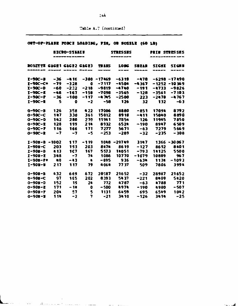
144
Table A.7 (continued)
OOT-OP-PLABB POKE LOADIK, P M , OB BOIZIB <60 LB)
•ICBO-S1E1II STIESSES PBIB STBBSSSS
BOSETTB CACE1 61CE2 6ICE3 TBABS LOBC SBEAB SIGBX SICBB
I -90C-B - 3 6 - • 1 6 -380 -17*69 -6318 - * 7 8 -6298 - 1 7 * 9 0 I -90C-C* - 7 9 -328 0 -7117 - * 5 0 * - * 3 6 7 -1252 -10369 I-90C-D - 6 0 -222 -218 -9819 - *7«0 - 1 9 1 - • 7 3 3 -9826 I-90C-B - • 8 -167 -158 -7098 -3565 - 1 2 8 -3561 -7103 I -90C-P - 3 6 -100 -117 - • 7 * 5 -2500 223 -2»78 - • 7 6 7 I-90C-B 5 0 - 2 -58 126 32 132 -63
0-90C-B 126 358 • 22 17006 8880 - 8 5 1 1709* 8792 O-90C-C 1*7 330 361 15012 8918 - • 1 1 150*0 8890 O-90C-D 1*2 280 270 119*1 735* 126 119*5 7850 0-90C-B 128 199 2 1 * 8932 652* - 1 9 0 89*7 6509 0-90C-P 116 166 171 7277 5671 - 6 3 7279 5669 O-90C-H - 7 - 7 -5 -253 -289 - 3 2 -235 - 3 0 8
I-90B-B --1002 117 -119 10*8 -297*9 31*7 1366 -30067 I-90B-C 203 153 203 8«7« 8619 - 1 2 7 8692 8*01 I-90B-D • 13 1C7 167 5573 1*051 - 7 9 3 1*125 5500 I -901-E 3*8 - 7 7* 1086 10770 -1079 10889 967 I -90B-P* *0 - * 3 « -895 936 -63« 113* - 1093 I-90B-B 217 117 79 *06 * 7737 509 7806 399*
0-90E-B «32 669 672 28087 21652 - 3 2 28987 21652 O-90B-C 97 1€5 202 8393 5*37 - 2 2 1 8*09 5*20 0-90V-0 152 19 2* 772 •787 - 6 3 •788 771 O-90B-B 171 - I B 0 -500 * 9 7 * -190 • 980 -507 0-90B-P 20* 57 5 1131 6*59 695 65*9 1042 0-901-1 1 1 * - 2 7 -21 3*10 -126 3 * 1 * - 2 5
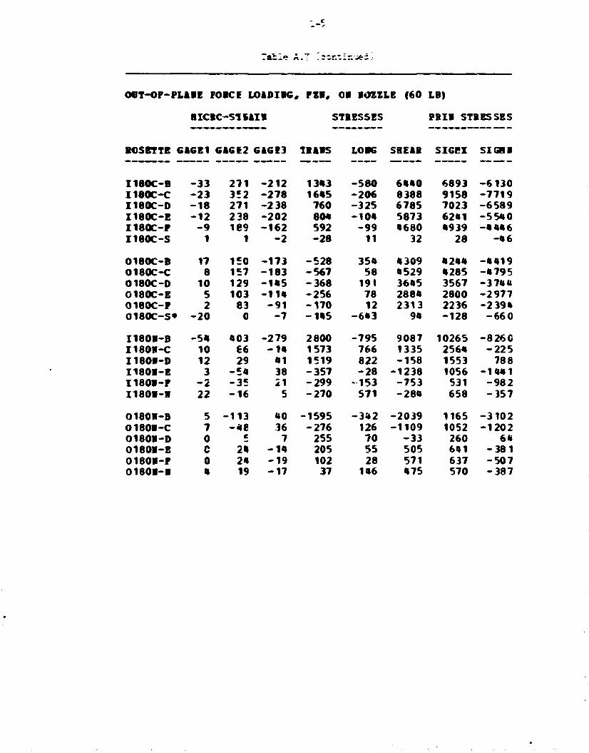
Table A.T '.zzT.;izi*z..
OOT-OF-PLABE FORCE LOADIBG, FEB, 08 IOZZLE (60 LB)
HICBC-SliAIR STRESSES PBIB STRESSES
ROSETTE G1GE1 GAGE2 GAGE3 TBABS LOK SHEAR SIGPI SIGHB
I180C-B - 3 3 2 7 1 -212 1343 -580 6440 6893 -6130 I180C-C - 2 3 352 -278 1645 -206 8388 9158 -7719 I180C-D - 1 8 271 -238 760 -325 6785 7023 -6589 I180C-E - 1 2 238 -202 804 -104 5873 6241 -5540 I180C-F - 9 ie9 -162 592 - 9 9 4680 4939 -4««6 I180C-S 1 1 - 2 - 2 8 11 32 28 - 4 6
0180C-B 17 150 -173 -528 354 4309 4244 -4419 O180C-C 8 157 -183 -567 58 4529 4285 -4795 0180C-0 10 129 - 1 * 5 -368 191 3645 3567 - 3 74 a C180C-E 5 103 - 1 1 * -256 78 2884 2800 -2977 O180C-F 2 83 - 9 1 -170 12 2313 2236 -2 394 0180C-S* - 2 0 0 - 7 -145 -643 94 -128 -660
I180B-B - 5 4 403 -279 2800 -795 9087 10265 -826C I180B-C 10 66 -m 1573 766 1335 2564 -225 I180B-D 12 29 41 1519 822 -158 1553 788 I180B-E 3 - 5 4 38 -357 - 2 8 -1238 1056 -1441 I180V-F - 2 - 3 5 21 -299 -153 -753 531 -982 I180B-B 22 - 1 6 5 -270 571 -284 658 -357
0180R-B 5 -113 MO -1595 -342 -2039 1165 -3102 O180B-C 7 - * e 36 -276 126 -1109 1052 -1202 0180B-0 0 c 7 255 70 - 3 3 260 6« 0180B-E C 24 - i n 205 55 505 641 - 3 8 1 0180B-F 0 2« - 1 9 102 28 571 637 -507 0180B-B 4 19 - 1 7 37 146 475 570 -387

IU6
Table A.f {cor.ti.-.uei}
OOT-OF-PLANE FOBCE LOADING, FZN, ON NOZZLE (60 LB)
HICRC-S1BAIN STRESSES PRIN STRESSES
ROSETTE GAGE1 GAGE2 GAGE3 TRANS LONG SHEAR SIGHX SIGHN
I270C-C 98 3C6 296 13120 6885 127 13123 6883 I270C-D 77 218 210 9320 5102 97 9322 5099 I270C-E 54 159 159 6914 3681 1 6914 3681 I 2 7 0 C - F 32 118 113 5049 2479 64 5051 2U77 I270C-H 4 54 49 2256 787 63 2258 784 I 2 7 0 C - J - 2 0 11 6 378 - 4 9 6 66 383 - 5 0 1 I270C-K - 3 0 - 4 - 9 - 2 4 5 - 9 8 4 67 - 2 3 9 - 9 9 0 I 270C-L - 3 0 - 1 7 - 1 4 - 6 4 7 - 1 1 0 1 - 5 2 - 6 4 1 - 1 1 0 7 I270C-H - 2 0 - 6 - 8 - 2 9 1 - 6 9 2 35 - 2 8 8 - 6 9 5 I270C-P - 1 0 C 1 32 - 2 9 0 - 6 32 - 2 9 0 I270C-B - 7 2 3 119 - 1 6 9 - 2 119 - 1 6 9 I 270C-T 2 - 4 0 - 9 0 47 - 6 4 72 - 1 1 5
C270C-B - 2 1 1 - 4 6 e - 5 1 3 - 2 1 3 2 8 - 1 2 7 3 3 600 - 1 2 6 9 1 - 2 1 3 7 0 O270C-C - 1 8 3 - 3 3 2 - 3 2 0 - 1 4 1 4 4 - 9 7 2 1 - 1 5 7 - 9 7 1 5 - 1 4 150 01'70C-D -166 - 2 6 1 - 2 6 1 -11292 - 8 3 6 7 - 2 - 8 3 6 7 - 1 1 2 9 2 O270C-E - 1 3 7 - 2 1 6 - 2 0 9 - 9 1 8 0 - 6 8 7 7 - 9 6 - 6 8 7 3 - 9 1 8 4 O270C-F -116 - 1 7 1 - 1 6 6 - 7 2 7 1 - 5 6 6 3 - 6 3 - 5 6 6 0 - 7 274 O270C-H - 7 1 - 1 0 4 - 1 0 4 -4499 - 3 4 7 5 0 - 3 4 7 5 - 4 499 O270C-J - 3 3 - 4 7 - 4 7 -2030 - 1 5 9 2 2 - 1 5 9 2 - 2 0 3 0 O270C-K - 7 - 1 4 - 1 4 - 6 0 2 - 3 8 1 0 - 3 8 1 - 6 0 2 O270C-L 15 10 10 422 567 0 567 422 O270C-H 17 12 12 520 667 - 2 667 520 0270C-P 8 5 8 271 312 - 3 1 329 255 027CC-R 3 3 5 169 136 - 3 2 188 117 O270t -T - 2 - 2 0 - 3 1 - 6 2 - 3 1 - 1 1 - 8 1
I270N-B 1090 24 64 735 32933 - 5 4 1 32942 726 I270N-C - 1 0 5 -2C5 - 1 8 6 - 8 4 9 1 - 5 7 0 3 - 2 5 3 - 5 6 8 1 - 8 513 I270N-D - 3 6 8 - 1 4 6 - 1 6 2 -6366 - 1 2 9 4 2 223 - 6 3 5 8 - 1 2 9 4 9 I270N-E - 3 3 2 - 3 8 - 7 9 - 2 2 0 9 - 1 0 6 2 2 542 - 2 1 7 5 - 1 0 6 5 6 I270W-F -265 12 - 2 4 32 - 8 ^ 5 7 478 60 - 8 085
O270N-B - 4 9 1 - 7 2 5 - 5 8 5 -28263 - 2 3 1 9 7 - 1 8 6 3 - 2 2 5 8 6 - 2 8 8 7 5 O270N-C - 9 7 - 1 9 2 - 1 9 0 -827^ - 5 3 9 9 - 3 2 - 5 3 9 9 - 8 279 O270N-D -130 - 2 6 - 2 3 - 9 9 4 - 4 2 1 1 - 6 4 - 9 9 3 - 4 2 1 2 O270N-E - 2 1 1 7 12 663 - 6 1 3 9 - b 3 663 - 6 1 4 0 O270N-F -240 5 12 €48 - 6 9 9 5 - 9 6 649 - 6 9 9 7 O270N-G - 2 5 2 . 5 - 9 -30 -7563 63 - 2 9 - 7 56 4 O270N-H - 2 4 9 - 7 - 1 6 - 2 3 4 - 7 5 4 8 127 -232 - 7 5 5 0 O270N-K - 2 2 5 - 1 5 7 1 - 6762 - 3 4 v 19 - 6 7 7 9 O270N-N - 1 4 7 - 2 - 1 1 - 1 3 2 - 4 4 4 7 126 - 1 2 8 - 4 4 5 0
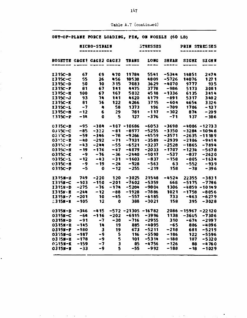
1*7
Table A.7 (continued)
00T-OF-PLAHE FOBCE LOiDIIG, FZN# OS NOZZLE (60 LB)
HICBO-SIBAIH STRESSES PBIH STRESSES
BOSETTE GAGE1 G1GE2 G4GE3 THUS LONG SHEAR S I G H SIGH!
I 3 1 5 C - B 67 £9 470 11784 5541 - 5 3 4 4 14851 2 4 7 4 I 3 1 5 C - C 55 26 456 10538 4809 - 5 7 2 6 14076 1 2 7 1 I 3 1 5 C - D 50 10 315 7083 3629 - 4 0 7 0 9777 93 5 I 3 1 5 C - F 81 67 141 4475 3778 - 9 8 6 5173 3 0 8 1 I 3 1 5 C - H 100 67 167 5032 4518 - 1 3 3 6 6135 3 4 1 4 I 3 1 5 C - J 93 74 141 4620 4179 - 8 9 1 5317 3 4 8 2 I 315C-K 81 76 122 4266 3715 - 6 0 4 4654 3 3 2 6 I 3 1 5 C - L - 7 4 58 1373 196 - 7 0 9 1706 - 1 3 7 I 3 1 5 C - H - 1 2 6 29 781 - 1 1 7 - 3 0 2 874 - 2 0 9 I 3 1 5 C - P - 1 4 0 5 127 - 3 7 6 - 7 1 137 - 3 8 6
03 15C-B - 9 5 - 3 8 4 - 1 0 7 - 1 0 6 8 6 - 6 0 5 3 - 3 6 9 8 - 4 0 0 6 - 1 2 7 3 3 0315C-C - 8 5 - 3 3 2 - 8 1 - 8 9 7 7 - 5 2 5 5 - 3 3 5 0 - 3 2 8 4 - 1 0 9 4 8 02i"JC-D - 5 9 - 3 4 6 - 7 8 - 9 2 6 6 - 4 5 5 9 - 3 5 7 1 - 2 6 3 5 - 1 1 1 8 9 03^5C-E - 4 0 - 2 9 2 - 7 1 - 7 9 3 1 - 3 5 8 9 - 2 9 3 9 - 2 1 0 6 - 9 4 1 4 0 3 U C - F - 4 3 - 2 4 4 - 5 5 - 6 5 2 1 - 3 2 3 7 - 2 5 2 8 - 1 8 6 5 - 7 8 9 4 0315C-H - 1 9 - 1 7 6 - 4 7 - 4 8 7 9 - 2 0 3 3 - 1 7 0 7 - 1 2 3 4 - 5 6 7 8 0315C-K - 9 - 7 6 - 3 6 - 2 4 4 0 - 1 0 1 7 - 5 3 7 - 8 3 7 - 2 6 2 0 0 3 1 5 O L - 1 2 - 4 3 - 3 1 - 1 6 0 3 - 8 3 7 - 1 5 8 - 8 0 5 - 1 6 3 4 0315C-H - 9 - 1 9 - 2 4 - 9 2 8 - 5 6 3 63 - 5 5 2 - 9 3 9 0315C-P - 5 0 - 1 2 - 2 5 5 - 2 1 9 158 - 7 8 - 3 9 6
I 3 1 5 I - B 749 - 2 2 0 120 - 3 0 2 5 21548 - 4 5 2 4 22355 - 3 8 3 1 I 3 1 5 I - C - 1 0 3 - 1 5 0 - 2 0 1 - 7 6 0 2 - 5 3 5 9 668 - 5 1 7 5 - 7 7 8 6 I315W-D - 2 7 5 - 7 6 - 1 7 4 -5204 - 9 8 0 4 1306 - 4 8 5 9 - 1 0 1 4 9 X315V-E - 2 4 4 - 1 2 - 8 8 - 1 9 2 8 - 7 8 8 6 1021 - 1 7 5 8 - 8 0 5 6 I 3 1 5 I - ? - 2 0 1 10 - 4 5 - 5 5 7 - 6 1 8 5 733 - 4 6 3 - 6 2 7 9 ; . 3 1 5 I - I - 1 0 5 12 0 368 - 3 0 2 1 158 395 - 3 0 2 8
0315B-B - 3 4 6 - 4 1 5 - 5 7 2 - 2 1 3 0 5 - 1 6 7 8 2 2086 - 1 5 9 6 7 - 2 2 1 2 0 0315H-C - 6 4 - 1 1 6 - 2 0 2 - 6 9 1 5 - 3 9 9 6 1138 - 3 6 0 5 - 7 3 0 6 0315N-D - 9 1 - 7 - 3 0 - 7 1 6 - 2 9 5 5 310 - 6 7 4 - 2 9 9 7 031511-E - 1 4 5 14 19 885 - 4 0 9 5 - 6 5 886 - 4 0 9 6 0 3 1 5 I - F - 1 8 0 3 19 673 - 5 2 1 1 - 2 1 8 681 - 5 2 1 9 03'-511-G - 1 8 7 - 9 5 116 - 5 5 9 0 - 1 8 6 122 - 5 5 9 6 03 15B-H - 1 7 8 - 9 5 101 - 5 3 1 4 - 1 8 8 107 - 5 3 2 0 0315H-K - 1 5 9 - 7 3 85 - 4 7 5 6 - 1 2 6 88 - 4 7 6 0 0 3 1 5 V - I - 3 3 - 9 5 - 5 5 - 9 9 2 - 1 8 8 - 1 8 - 1 0 2 9

U 8
Table A.8. Torsional moment loading, M _, on cylinder
TORSIOHAL ROBERT LOADIRG, HXC, OH CTLIROEB (30000 TI-LB)
RICBO-STBAIR STRESSES PBIR STRBSSBS
BOSBTTB GAGE1 GAGI2 GAGE3 TBAHS LORG SBEAB SIGBX SIGBR
I-O-C-C -3 -51 40 -225 -1*9 -1208 1022 -1396 I-O-C-D 2 -60 57 -71 41 -1557 1543 -1573 I-O-C-B 5 -53 *2 -21 130 -1398 1455 -1346 I-0-C-? 7 -46 f.2 138 247 -1302 1496 -1111 I-O-C-H 2 43 -39 87 83 1081 1166 -996 I-O-C-J 4 35 -39 -78 106 986 1005 -976 I-O-C-K 7 -34 35 23 207 -918 1037 -807 I-O-C-I* 0 -39 33 -127 -29 -954 877 -1033 I-O-C-B 4 -36 35 -21 123 -955 1009 -907 I-O-C-P -1 -32 37 131 23 -920 999 -845 I-O-C-S -3 -32 36 102 -64 -904 926 -888 O-O-C-B -5 55 -64 -199 -197 1578 1380 -1776 O-O-C-C 0 52 -57 -97 -25 1453 1J92 -1515 0-O-C-D -2 57 -54 61 -47 1484 1491 -1478 O-O-C-B -2 55 -57 -40 -77 1483 1424 -1541 0-O-C-F 3 50 -57 -152 32 1422 1365 -1435 0-O-C-H -2 45 -47 -41 -78 1231 1172 -1291 0-O-C-J 0 40 -47 -147 -35 1167 1078 -1259 O-O-C-K 0 38 -45 -147 -37 1105 1015 -1198 0-O-C-L 0 36 -38 -44 -5 980 955 -1004 O-O-C-B 0 38 -35 61 25 980 1023 -937 0-O-C-P 3 33 -40 -151 33 979 924 -1042 O-O-C-S -2 38 -35 63 -42 979 991 -«*70 I-O-H-B 7 -17 -24 -904 -57 96 -46 -915 I-O-R-C -10 -7 -22 -622 -476 191 -344 -754 I-O-H-0 -7 -5 -12 -362 -325 96 -246 -441 I-O-H-B -5 -7 -2 -206 -207 -63 -143 -270 I-O-H-P 0 -7 0 -159 -49 -96 7 -215 I-O-H-H 2 0 2 48 85 -32 104 30 0-O-H-B 0 17 -24 -149 -40 537 446 -634 O-O-H-C -2 -2 0 -38 -76 -31 -20 -93 0-O-H-D -a -7 12 125 -91 -250 290 -255 0-O-H-B -2 -9 10 14 -54 -251 233 -273 O-0--H-F -2 -7 10 70 -36 -223 246 -212 0-O-H-H -2 -7 7 14 -57 -190 171 -215 O-O-H-K -2 -5 3 -42 -f6 -93 40 -1*8 0-O-H-H -2 0 -1 -1 -61 13 1 -64
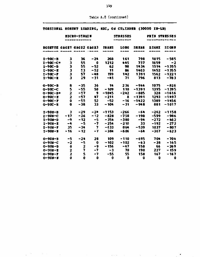
1»»9
Tafcle A.8 (ccnti n'Jed)
TOBSIOBAL H08EIT LOADIBG, IXC, 0 « CTLIIDBB {30000 IB-LB)
BICBO-STBAIB STRESSES PBII STRESSES
BOSBTTE GAGE1 G1GE2 GIGE3 TBABS LOBG SBBAB SIGBI SIGBB
I-90C-B 3 36 -2* 268 161 798 1015 -585 I-90C-C* 3 55 0 1212 •*5 737 1659 -2 I-90C-D 3 55 -52 62 98 1*3* 151* -1355 I-90C-B 3 £3 -52 11 86 1*03 1*52 -1355 I-90C-F 3 57 -•8 199 142 1391 1562 -1221 I-90C-B 3 29 -31 -•1 71 796 813 -783 O-90C-B 8 -35 36 1* 236 -9«* 1075 -826 O-90C-C 5 -55 50 -109 110 -1391 1395 -1395 0-90C-D* 2 -57 9 -10*5 -2*2 -885 328 -1616 0-90C-B 2 -57 •7 -211 8 -1391 1293 -1*97 O-90C-P 0 52 -52 -16 -1*22 1389 -1*56 O-90C-B 0 -38 33 -10* -31 -9*8 881 -1017 I-90I-8 3 -29 -2* -1153 -266 -6* -262 -1158 I-90B-C -17 -26 -12 -828 -738 -190 -599 -986 I-90I-D -9 -12 -S -35* -380 -9* -272 -*62 I-90I-E -* -5 -7 -254 -210 33 -192 -272 I-90B-P 35 -3* 7 -633 86* -539 1037 -807 I-90I-B -16 -12 -7 -38* -606 -6* -367 -623 O-90B-B -5 -2* 28 109 -110 -695 70* -70* O-90R-C -2 -5 0 -102 -102 -63 -38 -165 O-901-D 0 2 -9 -156 -*7 158 66 -269 O-901-E 2 7 -7 -3 70 190 227 -159 O-901-F 2 5 -7 -55 55 158 167 -167 O-90B-B 0 0 0 0 0 0 0 0

150
Table A.8 (continued)
TOBSIOI1L HO BEIT L01DIIG, BXC, OB CYLIBDEB (30000 IB-LB)
B7CBO-S1B1IB STRESSES PRII STBESSES
BOSETTE GiGEI G1GI2 GIG13 TBIBS LOIG SHEAB SIGBX SIGBB
I180C-B 5 - 2 1 27 126 187 -636 793 - * 8 1 I180C-C 5 - * » 50 111 182 -1255 1*02 -1108 I180C-D 5 - * 9 55 112 181 -1382 1532 -1232 I180C-E 3 - 52 52 12 83 -1382 1*30 -1336 I180C-P 3 - * 7 •7 9 80 -1256 1301 -1213 I180C-S 3 - 2 8 3* 125 128 -816 9*3 - 6 9 0
O180C-B 3 50 - 5 7 - 1 * 5 «2 1*29 1381 - 1 * 8 3 O180C-C 1 53 - 5 7 -87 -8 1*57 1*10 -1505 C180C-D 5 55 - 5 9 -101 131 152* 15** -1513 0180C-E 5 55 - 5 7 - * 5 1*5 1*91 15«* - 1 * * 5 O180C-F 0 50 - 5 7 -174 - 6 * 1*26 1308 - 1 5 * 6 0180C-S* 0 28 - * 1 -277 -83 917 7*1 -1102
I180B-B 3 - 2 - 1 9 - • • 6 - * • 226 58 - 5 * 7 I180B-C - 2 1 - 1 6 - 3 * 2 -^©0 22* -10 - * 9 3 I 1 8 0 I - D - 2 - 1 1 -289 -1 *2 128 - 6 7 -363 I180B-E 0 - 2 - * - 1 3 * -25 3* -16 - 1 * * I180B-P 0 - 2 5 61 26 -93 138 - 5 1 I180B-B - 2 1 - 2 -21 -63 3* - 2 - 8 2
0180B-B - 1 0 i« - 7 161 -2*5 28* 307 - 3 9 1 Ot80B-C 2 0 0 - 1 * 60 - 1 60 - 1 * 0180B-D 2 - 1 0 5 -117 25 -192 159 - 2 5 1 O180B-E 2 - 10 9 - 8 58 -256 283 -233 01803-P 2 - 7 7 - 6 65 -190 222 -163 O180I-B 0 0 0 -15 -16 0 - 1 5 -16

151
Table A.8 (continued)
TORSIOBAL BOBEBT ICiDIBG, BXC, OB CTLIBDEB (30000 IB-LB)
BICBO-STB1IB STBESSSS PBIB STBESSBS
BOSETTE G16E1 6 i 6 E 2 6A6E3 TBABS L0B6 SBE&B SI6BX 5I6BB
I 2 7 0 C - C - 1 58 -5f t 100 - 1 2 1493 1538 - 1 4 5 0 I 2 7 0 C - D 1 €1 -5f t 151 75 1528 1642 - 1 4 1 6 I 2 7 0 C - B 0 58 -5f t 7ft 35 1493 1548 - 1 f t 3 9 I 2 7 0 C - P - 2 53 - 5 0 76 - 3 5 1366 1388 - 1 3 * 7 I 2 7 0 C - B 1 46 - f t5 23 22 1207 1229 - 1 1 8 f t I 2 7 0 C - J 5 36 -ftO -9ft 129 1017 1041 - 1 0 0 6 I270C-K - 2 31 - 3 5 - 8 8 - 9 0 891 802 - 9 8 0 I 2 7 0 C - L - 2 28 - 3 3 - 1 0 6 - 9 4 815 715 - 9 1 5 I 2 7 0 C - B - 2 3ft - 3 1 76 - 3 4 859 882 - 8 f t 0 I 2 7 0 C - P 0 3« - 3 8 - 9 5 - 3 0 951 889 -101 f t I 270C-B 2 41 - 3 6 100 96 1022 1120 -92 f t I 2 7 0 C - T 5 17 - 1 9 - 6 6 123 ft79 516 - 4 5 9
0270C-B - 2 - 5 5 60 107 - 3 9 - 1 5 2 2 1558 - 1 4 9 0 O270C-C - 5 - 5 2 57 119 - 1 0 0 -1 f t58 1471 - 1 4 5 2 0270C-D 0 - 5 7 53 - 9 5 - 2 1 - 1 4 6 0 1402 - 1 5 1 8 O270C-E 0 - 5 7 53 - 9 5 - 2 1 - 1 4 5 8 1401 - 1 5 1 7 0270C-P 0 - 5 2 53 10 10 - 1 3 9 5 1405 - 1 3 8 5 O270C-B -a - 5 0 50 17 - 1 2 9 - 1 3 3 2 1278 - 1 3 9 0 O270C-J 0 - f t7 ft8 14 13 - 1 2 6 7 1281 - 1 2 5 3 O270C-K 3 -ftO 43 59 96 - 1 1 1 0 1188 - 1 0 3 2 O270C-L 3 - 4 3 38 - 9 5 50 - 1 0 7 7 1058 - 1 1 0 2 O270C-B 1 - 3 8 36 - 3 3 6 - 9 8 5 972 - 9 9 9 O270C-P -ft -ftO 3ft - 1 3 0 - 1 6 2 - 9 8 2 836 - 1 1 2 8 O270C-B - 2 - • 0 3ft - 1 3 7 - 9 6 - 9 8 4 867 - 1 1 0 1 O270C-T* 1 - f t2 0 - 9 3 1 - 2 5 5 - 5 6 4 65 - 1 2 5 0
I 2 7 0 B - B 0 7 ft 250 63 32 255 57 I 270B-C 4 - 2 12 198 193 - 1 8 9 385 6 I270B-D ft 0 9 199 19ft - 1 2 7 32ft 6 9 I 2 7 0 B - E ft 2 2 93 161 1 161 93 I 2 7 0 B - F 3 5 - 2 51 105 95 177 - 2 1
O270B-B - 2 - 2 8 2ft - 9 5 - 9 2 - 6 9 4 600 - 7 8 7 O270K-C - 2 - 5 3 -ft4 - 8 0 - 9 5 3ft - 1 5 9 O270B-D - 2 7 - 7 3 - 7 1 190 160 - 2 2 8 O270B-E 0 10 - 1 0 0 0 254 25ft - 2 5 4 O270B-P 0 7 - 1 0 - 5 2 - 1 6 222 189 - 2 5 7 O270B-G - 2 7 - 1 0 - 5 0 - 8 6 ?22 155 - 2 9 1 O270W-H - 2 7 - 1 0 - 5 0 - 8 6 222 155 - 2 9 1 O270B-K - 2 2 - 2 3 - 7 1 63 39 - 1 0 7 O270K-B - 2 - 2 - 2 - 1 0 2 - 1 0 2 0 - 1 0 2 - 1 0 2

152
Table A.8 (continued)
TOBSIOHAL HOHBHT ICADIHG, F.XC, OH CTLIHDBB (30000 IH-LB)
HICBO-STEAIR STBESSES PBIH STBESSBS
BOSBTTB G4GE1 GAGE2 GIJE3 TBAHS LONG SBEAB SIGHX SIGHH
I315C-B 12 - 9 1 - 7 8 -3725 -755 -161 -747 -3734 I315C-C 12 - 6 2 - 5 2 -2517 -390 -127 -383 - 2 525 I315C-D 9 - 4 9 - 3 6 -1871 -278 -181 -257 -1891 I315C-P 0 - 2 6 - 2 6 -1140 -333 0 -333 -1140 I315C-H - 2 - 2 1 - 2 8 -1080 -384 94 -372 -1092 I315C-J 3 - 1 9 - 2 6 -983 -212 96 -200 -994 I315C-K 8 - 2 1 - 2 4 -991 - 7 0 32 - 6 9 - 992 I315C-L 41 - 1 9 - 2 4 -988 923 58 924 - 9 9 0 I315C-H 43 - 2 8 - 1 7 -1035 988 -157 1000 -1047 I315C-P 44 - 2 2 - 2 1 -985 1011 - 7 1011 - 9 8 5
0315C-B 5 - 3 3 - 2 6 -1308 -250 - 9 5 -242 -1317 0315C-C 9 - 2 1 - 1 7 -844 31 - 6 3 36 -849 0315C-D 14 - 2 1 - 1 9 -902 156 - 3 2 157 - 903 0315C-E 26 - 1 9 - 1 4 -758 555 - 6 3 558 - 7 6 1 0315C-P 28 - 2 8 - 1 4 -969 563 -190 586 - 993 0315C-H* 0 - 1 4 - 1 6 -667 -200 32 -198 - 6 6 9 0315C-K 38 - 1 6 - 1 9 -815 902 30 902 -815 0315C-L 41 - 1 6 - 2 1 -865 959 63 962 -868 0315C-H 45 - 1 9 - 2 4 -979 1064 64 1066 - 9 8 1 0315C-P 45 - 2 6 - 1 9 -1028 1050 - 9 3 1054 -103 3
I315H-B 5 - 7 9 - 8 1 -3521 -907 31 -906 -3522 I315H-C - 3 6 - 5 2 - 5 2 -2263 -1748 - 1 -1748 -226 3 I315H-D - 2 8 - 3 3 - 3 1 -1376 -1267 - 3 2 -1259 -1385 I315H-E - 1 9 - 1 9 - 1 9 -808 -808 1 -807 -809 I315H-P - 1 2 - 1 2 - 1 4 -554 -517 33 -498 -573 I 3 1 5 H - I * - 3 0 -282 -6190 -1953 3765 248 -8392
0315H-B 13 - 3 1 - 2 1 -1154 42 -124 55 -1167 0315H-C 5 14 19 731 368 - 6 2 741 358 0315H-0 - 1 1 14 19 752 -112 - 6 6 757 - 1 1 7 0315H-E - 4 12 12 531 31 - 2 531 3 1 0315H-P - 9 8 10 392 -147 - 3 0 394 - 1 4 9 0315H-G - 6 5 5 238 -123 2 238 - 123 0315H-H - 9 3 3 131 -226 0 131 - 226 0315W-K - 4 - 2 - 4 -124 -164 29 -109 - 1 7 9 0315H-H - 3 9 - 2 - 2 - 3 4 -1187 0 - 3 4 -1187

153
ils A.9. Out-cf-plaae aceseat lo&disg, IL , 00 cyl inder
OOT-OF-PLABE BO BE 11 LOADIBC, BTC. 0 1 CYLIBDEE (80000 II -LB)
BICBC-S1B1IB STBESSES PBII STRESSES
BOSETTE 616E1 GIG 12 6AGE3 T H I S LOK SBEIB SIGBI SIGH!
I -O-C-C 0 - 1 9 - 1 4 -734 -220 - 6 « -212 - 7 4 2 I-O-C-D 0 - 1 7 - 1 9 -786 -236 32 -234 - 7 8 8 I -O-C-E 5 - 1 7 - 1 9 -792 - 9 4 32 - 9 3 - 7 9 3 I -O-C-F 5 - I B - 2 1 -792 - 9 4 95 - 82 - 804 I-O-C-B 7 - 2 1 - 1 7 - 8 * 7 - 3 9 - 6 * - 3 4 - 8 5 2 I -O-C-J 10 - 2 4 - 1 2 -797 • 7 -159 76 - 8 2 6 I-O-C-K 12 - 1 2 - 2 4 -799 118 159 145 - 8 2 6 I -O-C-L* -122 - S - 2 1 -529 -3821 158 -522 -3828 I-O-C-B 12 - 9 - 2 4 -733 150 192 190 - 7 7 3 i-o-c-p 12 - 9 - 1 8 -620 185 125 204 - 6 3 9 1-0-C-S 15 - 2 - 1 2 -330 350 1«1 378 - 3 5 8
0-O-C-B 9 12 12 505 430 1 505 430 0-O-C-C 7 1« 16 659 406 - 3 2 663 402 0-O-C-D 9 16 19 762 505 - 3 0 765 501 0-O-C-E 9 19 21 862 5 3 * - 2 9 865 532 o-o-c-r 9 19 21 866 53« - 3 2 869 531 0-O-C-B 12 1€ 23 861 605 - 9 4 892 574 0-O-C-J 11 16 23 860 600 - 9 2 889 571 0-O-C-K 16 16 21 802 728 - 6 3 838 691 0-O-C-L 14 16 21 807 657 - 6 4 830 633 0-O-C-B 14 1€ 21 806 659 - 6 4 830 635 0-O-C-P 16 14 19 700 698 - 6 2 761 637 0-O-C-S 19 7 16 488 702 -127 761 430
I - O - i - B - 2 9 - 7 - 1 0 -337 -963 32 -335 - 9 6 5 I - O - I - C - 1 2 2 5 171 -308 - 3 2 173 - 3 1 0 I-O-B-D - 5 2 5 163 - 9 5 - 3 2 167 - 9 9 I -O-B-E - 5 2 2 111 -111 0 111 - 1 1 1 I -O-B-P - 5 2 2 111 -111 0 111 - 1 1 1 I-O-B-l l 0 0 0 0 0 0 0 0
0-O- I -B - 1 0 9 9 • 17 -167 - 1 417 -167 0-O-B-C - 1 5 4 * 207 -375 - 1 207 - 375 0 -O- I -D - 1 2 2 0 54 -3»9 30 56 - 3 5 1 O-O-l-E - 1 0 2 0 54 -277 31 57 - 2 8 0 0-O-B-F - 7 0 0 - 3 -22» 1 - 3 -224 0-O-B-B - 5 C 0 - 2 -150 1 - 2 - 1 5 0 0-O-W-I 2 0 0 - 8 56 - 1 56 - 8 O-O- i -B* 2 2 - 4 1 -868 -197 580 138 -1203

Table A.9 (continued'
OOT-OP-PLAH* HO HE IT f.OADIRG, HTC, OH CYLIHDEB (80000 II-LB)
HIC80-STEAIR STRESSES PRIR STRESSES
ROSETTE GAGE1 GAGE2 GAGE3 TEARS LORG SHEAR S I G H SIGHR
I - 9 0 C - B - 5 -3a - 2 6 - 1 3 1 0 - 5 3 7 - 9 6 - 5 2 5 - 1 3 2 2 I - 9 0 C - C * - 1 2 - 3 * 0 - 7 2 3 - 5 7 6 - 4 4 7 - 1 9 7 - 1 1 0 2 I - 9 0 C - D - 1 2 - 3 4 - 2 2 - 1 1 9 7 - 7 1 8 - 1 5 9 - 6 7 0 - 1 2 4 5 I - 9 0 C - E - 1 4 - 3 6 - 2 2 - 1 2 a 7 - 8 0 5 - 1 9 1 - 7 3 4 - 1 3 1 8 I - 9 0 C - F - 1 4 - 5 - 2 4 - 6 1 6 - 6 1 6 255 - 3 6 0 - 8 7 1 T-90C-R 77 - 1 2 2 - 1 2 0 - 5 3 9 7 679 - 3 2 679 - 5 3 9 7
O-90C-B 16 9 14 488 632 - 6 6 658 463 O-90C-C 22 c 0 91 678 64 685 84 O-90C-D 26 - 4 - 9 - 3 2 a 697 59 700 - 3 2 7 O-90C-E 29 - 9 - i a - 5 a 3 702 64 705 - 5 4 6 O-90C-F 33 - 1 2 -2a - 8 0 9 761 159 777 - 8 2 5 O-90C-R 19 - 1 5 1 - 1 5 8 - 6 8 1 7 - 1 4 6 5 85 - 1 4 6 4 - 6 8 1 9
I - 9 0 R - B - 6 0 0 - i a - 2 4 8 - 1 8 6 2 191 - 2 2 6 - 1 8 8 4 I - 9 0 R - C 5 5 5 204 204 0 204 20 4 I - 9 0 R - D 16 2 7 189 550 - 6 5 561 178 I - 9 0 R - E 14 2 - 1 8 C17 - 6 5 426 - 2 7 I - 9 0 R - P - 2 4 - 1 2 12 26 - 7 0 8 - 3 1 8 145 - 8 2 6 I - 9 0 R - R - 1 9 - 1 4 - 1 1 - 5 3 6 - 7 2 1 - 3 2 - 5 3 1 - 7 2 6
O-90R-B 22 29 29 1239 1024 0 1239 1024 O-90R-C 3 7 10 376 193 - 3 3 381 187 O-90R-D 3 3 3 116 117 - 2 118 115 O-90R-E 5 0 3 59 176 - 3 1 184 5 2 O-90R-P 5 0 3 60 172 - 3 0 179 52 O-90R-R - 4 - 2 0 - 3 3 - 1 4 3 - 3 1 - 2 5 - 1 5 1
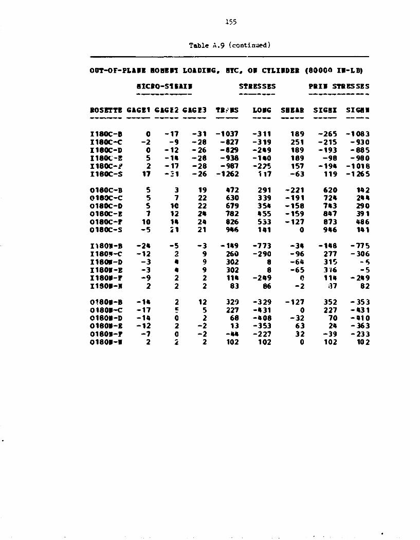
155
Table A.9 (continued)
O0T-OF-PL1BE BO HE 11 LOIDIBG, BYC, OB CTLIBDEB ( 8 0 0 0 0 IB-LB)
BICBO-SIBAIB STBESSES PBIB STRESSES
BOSETTE GAGE1 G1GE2 G1GE3 TB.-BS LOIG SBEIB SIGBZ SIGflB
I180C-B 0 - 1 7 - 3 1 -1037 -311 189 -265 -1083 I180C-C - 2 - 9 - 2 8 -827 -319 251 -215 -930 I180C-D 0 - 1 2 - 2 6 -829 -249 189 -193 -885 I180C-E 5 - I B - 2 8 -938 -140 189 - 9 8 - 980 I180C-J? 2 - 1 7 - 2 8 -987 -225 157 -194 -1018 I180C-S 17 - 3 1 - 2 6 -1262 117 - 6 3 119 -1265
0180C-B 5 3 19 472 291 - 2 2 1 620 142 0180C-C 5 7 22 630 339 - 1 9 1 724 244 0180C-0 5 10 22 679 35« -158 743 290 0180C-E 7 12 24 782 455 -159 847 391 0180C-F 10 IB 24 826 533 -127 873 486 O180C-S - 5 21 21 9*6 141 0 946 141
I180B-B - 2 * - 5 - 3 -149 -773 - 3 4 -148 -775 I180J-C - 1 2 2 9 260 -290 - 9 6 277 -306 I180B-0 - 3 « 9 302 8 - 6 4 315 - 5 I180B-E - 3 4 9 302 8 - 6 5 316 - 5 I180B-P - 9 2 2 1 1 * -249 0 114 - 249 I1S0B-B 2 2 2 83 86 - 2 37 82
O180B-B - 1 4 2 12 329 -329 -127 352 - 353 O180B-C - 1 7 c 5 227 -431 0 227 - 4 3 1 O180B-D - 1 * 0 2 68 -408 - 3 2 70 - 4 1 0 0180B-E - 1 2 2 - 2 13 -353 63 24 -363 0180B-P - 7 0 - 2 - 44 -227 32 - 3 9 -233 0180B-B 2 2 2 102 102 0 102 102
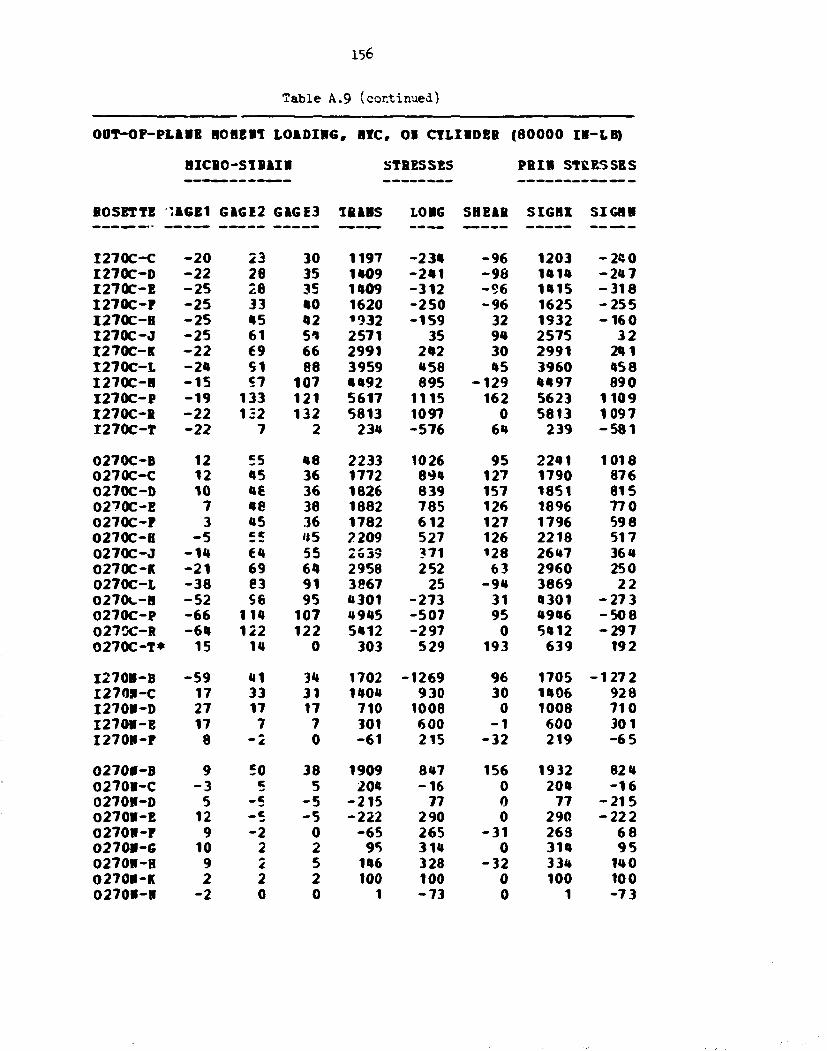
156
Table A.9 (continued)
O0T-OP-PL1BE BOBEB1 LOADIRG, BYC, 01 CYLIBDEB (80000 IR-LB)
BICBO-S1BAIB STRESSES PBII STRESSES
BOSETTE ',1GE1 G1GE2 G1GE3 IBiBS LOBG SHEAB SIGBX SIGBB
I 270C-C - 2 0 23 30 1197 - 2 3 4 - 9 6 1203 - 2 4 0 I270C-D - 2 2 28 35 1409 - 2 4 1 - 9 8 1414 - 2 4 7 I 2 7 0 C - E - 2 5 28 35 1409 - 3 1 2 - 9 6 1415 - 3 1 8 I 2 7 0 C - P - 2 5 33 40 1620 - 2 5 0 - 9 6 1625 - 2 5 5 I 2 7 0 C - B - 2 5 45 42 *932 - 1 5 9 32 1932 - 1 6 0 I 2 7 0 C - J - 2 5 61 5 * 2571 35 94 2575 3 2 I270C-K - 2 2 69 66 2991 242 30 2991 241 I 2 7 0 C - L - 2 4 S1 88 3959 458 45 3960 458 I 2 7 0 C - B - 1 5 «7 107 4492 895 - 1 2 9 4497 890 I 2 7 0 C - P - 1 9 133 121 5617 1115 162 5623 1109 I270C-R - 2 2 132 132 5813 1097 0 5813 1097 I 2 7 0 C - T - 2 2 7 2 234 - 5 7 6 64 239 - 5 8 1
0270C-B 12 55 48 2233 1026 95 2241 1018 0270C-C 12 05 36 1772 894 127 1790 876 0270C-D 10 46 36 1826 839 157 1851 815 0270C-E 7 «e 38 1882 785 126 1896 770 0270C-P 3 U5 36 1782 612 127 1796 598 0270C-B - 5 c t U 5 2209 527 126 2218 517 0270C-J - 1 * €4 55 2S33 ?71 128 2647 364 0270C-K - 2 1 69 64 2958 252 63 2960 250 0270C-L - 3 8 e3 91 3867 25 - 9 4 3869 2 2 0270C-B - 5 2 se 95 4301 - 2 7 3 31 4301 - 2 7 3 O270C-P - 6 6 114 107 4945 - 5 0 7 95 4946 - 5 0 8 027GC-B - 6 * 122 122 5412 - 2 9 7 0 5412 - 2 9 7 0 2 7 0 C - T * 15 14 0 303 529 193 639 192
I270B-B - 5 9 41 34 1702 -1269 96 1705 - 1 2 7 2 I270SI-C 17 33 31 1404 930 30 1406 928 I270B-D 27 17 17 710 1008 0 1008 710 I 2 7 0 B - E 17 7 7 301 600 - 1 600 301 I 2 7 0 B - P 8 - 2 0 - 6 1 215 - 3 2 219 - 6 5
O270B-B 9 50 38 1909 847 156 1932 824 0270B-C - 3 c 5 204 - 1 6 0 204 - 1 6 0270B-D 5 - 5 - 5 - 2 1 5 77 0 77 - 2 1 5 0270B-E 12 _ e - 5 - 2 2 2 290 0 290 - 2 2 2 0270B-P 9 - 2 0 - 6 5 265 - 3 1 263 6 8 0270B-G 10 2 2 95 314 0 314 9 5 0270W-H 9 0*
i. 5 146 328 - 3 2 334 140 O270B-K 2 2 2 100 100 0 100 100 0270V-B - 2 0 0 1 - 7 3 0 1 - 7 3

OOT-OF-PLARB HO BE IT LOiDIRG, BTC. OB CTLIHDEB (80O00 I9-LB}
HICBO-S1BAIH STBESSBS PBIH STBESSES
BOSETTE GAGE1 GiGE2 GAGE3 TBABS LOBG SBEAB SIGBX SIGHI
I 315C-B - 9 26 - 2 3 78 - 2 5 8 665 J 9 6 - 7 7 6 I315C-C - 7 31 - 3 3 - 2 8 - 2 1 5 859 7ft2 - 9 8 6 I 3 1 5 C - D - 5 34 - 3 3 16 - 1 3 9 888 830 - 9 5 3 I 3 1 5 C - P - 9 12 - • 185 - 2 2 0 223 283 - 3 1 9 I 315C-H - 7 15 -1ft 30 - 1 9 3 380 315 - » 7 8 I 3 1 5 C - J -ft 20 -1f t 129 - 9 1 445 478 -ftftO I315C-K 3 29 - m 329 186 572 83ft - 3 1 9 I 3 1 5 C - L 31 82 - 1 9 133ft 1333 1346 2680 - 1 3 I 3 1 5 C - H 52 94 - 2 2 1539 2033 15ft5 3351 221 I 3 1 5 C - P 62 125 - 1 5 23ft3 2553 1856 • 3 0 7 589
0315C-B 7 15 26 891 ft 92 - 1 5 8 946 • 3 7 0315C-C 12 1ft 29 938 646 - 1 9 1 1032 552 0315C-D 15 12 • 3 1192 793 - f t 1 1 1449 536 0315C-E 1« 12 ft5 12«5 805 -« f t3 1520 531 0315C-P 19 3 50 1139 919 - 6 2 9 1667 391 0315C-H 21 7 52 1282 1027 - 6 0 1 1768 540 C315C-K 26 - 2 69 1ft33 121« -9 f t9 2279 369 0315C-L 26 - 2 6 88 1330 1184 - 1 5 T 7 2776 - 2 6 2 0315C-H 31 - 2 6 102 1636 1418 - 1 7 0 7 3237 - 1 8 3 0315C-P 33 - 3 5 123 1895 1566 - 2 1 1 7 3854 - 3 9 3
I 3 1 5 H - B - • 3 21 5 622 - 1 1 1 1 22ft 650 - 1 140 I315R-C 7 12 m 562 378 - 3 1 567 37 3 I 315R-D 12 5 7 239 ft 25 - 3 2 ft 30 23« I 3 1 5 B - B 7 0 0 - 1 9 20-, - 1 202 - 1 9 I 3 1 5 I - P 2 0 0 -1ft 61 - 1 61 •1ft I 3 1 5 H - B 0 - 2 0 - 5 2 - 1 6 - 3 1 3 -7 0
0315B-B - 5 19 33 115* 209 - 1 8 9 1191 173 0315R-C - 1 7 5 2 177 - 4 4 4 32 178 - • 4 5 0215R-D - 9 3 - 9 -12ft - 3 0 2 150 - 3 9 - 3 8 8 0315R-E - f t 2 - 9 -1f t2 - 1 7 0 151 -ft - 3 0 8 0315H-F 1 1 - 9 - 1 8 2 - 3 1 127 41 -25 f t 03151-G - 2 3 - 9 - 1 2 2 - 8 5 160 57 -26 f t 0315R-B - 2 3 - 7 - 8 1 - 7 5 124 46 - 2 0 2 0315R-X - 2 1 - 2 - 2 0 - 5 9 29 -ft - 7 ft 0315R-R - • 1 — d. -ft - 8 0 - 1 2 5 2 31 - 7 9 - 1 2 5 3
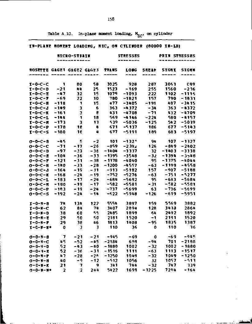
158
Table A.10. In-plane moment loading, M-,,, on cy l inder
IH-PLAHE ROHEVT LOIDIRG, HZC, OH CTLIIIDBR (80000 IB-LB)
HICRO-STF1IH STRESSES PRIR STRESSES
ROSETTE GiGEI 6&6I2 G16E3 TRAMS LORG SHEAP SIGHT SIGKH
I -O-C-C 1 80 58 3025 928 287 3063 189 I -O-C-D - 2 1 00 25 1523 - 1 6 9 255 1560 - 2 1 6 I -O-C-E - a 7 32 15 1079 - 1 0 9 3 222 1102 - 1 1 1 6 I -O-C-F - 6 9 22 10 780 - 1 8 2 1 157 790 - 1 8 3 1 I -O-C-H - 1 1 8 1 15 »77 - 3 0 0 5 - 1 9 1 087 - 3 0 1 5 I -O-C-J - 1 0 9 3 6 363 - 0 372 - 3 0 363 - 0 3 7 2 I-O-C-K - 1 6 1 3 8 a31 - 0 7 0 8 - 7 1 032 - 0 7 0 9 I -O-C-L - 1 0 0 1 18 569 - 0106 - 2 2 0 580 - 0 1 5 7 I -O-C-H - 1 7 3 3 13 539 - 5 0 3 6 - 1 2 5 50 2 - 5 0 3 9 I -O-C-P - 1 7 8 i e a 671 - 5 1 3 7 186 677 - 5 1 0 3 I -O-C-S - 1 8 0 16 a 677 - 5 1 9 1 189 683 - 5 1 9 7
0-O-C-B - 0 5 c - 2 101 -132" 1 90 107 - 1 3 2 7 o-o-c-c - 7 1 - 1 7 - 2 6 - 8 5 9 - 2 3 9 * 126 - 8 0 9 - 2 0 0 2 0-O-C-D - 9 7 - 3 3 - 3 6 - i a o « - 3 3 37 32 - 1 0 0 3 - 3 3 3 8 0-O-C-E - 1 0 0 - 3 6 - 3 3 -1395 - 3 5 0 8 - 3 2 - 1 3 9 0 -3*>08 0-O-C-P - 1 2 1 - 3 1 - 3 8 - 1 1 7 8 - 0 0 0 0 95 - 1 3 7 5 - 0 0 0 0 0-O-C-H - 1 0 0 - 3 3 - 2 8 - 1 2 0 0 -0557 - 6 3 - 1 1 9 9 - 0 5 5 8 0-O-C-J - 1 6 0 - I S - 3 1 - 9 1 3 - 5 1 8 2 157 - 9 0 7 - 5 1 8 8 0-O-C-K - 1 6 8 - 2 1 - 1 9 - 7 5 2 - 5 2 7 6 - 6 3 - 7 5 1 - 5 2 7 7 0-O-C-L - 1 8 3 - 1 7 - 2 a - 6 8 0 - 5 6 8 2 95 - 6 8 3 - 5 6 8 0 0-O-C-H - 1 8 0 - 1 9 - 1 7 - 5 8 2 - 5 5 8 1 - 3 1 - 5 8 2 - 5 5 8 1 0-O-C-P - 1 9 3 - 1 9 - 2 a - 7 3 7 - 5 6 9 9 63 - 7 3 6 - 5 6 9 9 o-o-c-s - 1 9 2 - 2 a - 1 0 - 6 2 2 - 5 9 0 8 - 1 2 6 - 6 1 9 - 5 9 5 1
I - O - H - B 7tt 13a 12? 5550 3897 159 5569 3882 I -O-W-C 62 8a 7a 3a 07 2890 128 3033 2860 I - O - I I - O 38 60 15 2a 85 1899 60 2092 1892 I -O -W-E 29 50 50 2181 1520 - 1 2131 1520 I -O -W-P 29 38 a6 1813 1008 - 9 5 1835 1387 I - C - W - l l * 0 3 3 110 36 0 110 36
O _ 0 - H - B 7 - 2 1 - 2 1 - 9 0 5 - 6 9 0 - 6 9 - 9 0 5 0 - O - S - C as - 5 2 - a 5 -2180 698 - 9 0 701 - 2 1 8 0 0 -O-H-D 52 - a 3 -ao - 1 8 8 0 1002 - 3 2 1002 - 1 8 8 0 0 - 0 - ^ - E 52 - 3 6 - 3 1 -1516 1111 - 6 3 1113 - 1 5 1 7 O-O- l i -P U7 - 2 8 - 2 * - 1 2 5 0 1009 - 3 2 1009 - 1 2 5 0 0-O-W-H UO - 9 - 1 2 -512 1056 32 1057 - 5 1 3 O-C-H-K 21 7 9 301 700 - 3 2 707 339 0 -O-R-R* 2 2 2UU 5022 1698 - 3 2 2 5 7 2 * 0 - 1 6 0

IW-PLAWE HOflERT LOAPIHG, B2C, 0!l CYLINDER (80000 IH-LB)
HICRO-S1MI1I STRESSES PRIM STRESSES
ROSETTE GAGE1 GAGE2 GAGE3 TRAWS LOHG SHEAR rIGHX SIG3R
I - 9 0 C - B 98 - 3 8 7 - 3 8 5 -17083 - 2 1 7 5 - 3 1 - 2 1 7 5 - 1 7 0 8 3 I - 9 0 C - C * ^8 - 2 7 * 0 - 6105 - 102 - 3 6 6 3 1632 - 7 8 3 9 I - 9 0 C - D 50 - 2 3 2 - 2 0 3 - 9 6 1 0 - 1 3 7 2 - 3 3 3 - 1 3 5 0 - 9 6 3 2 T -90C-E 53 - 1 9 8 - 1 7 0 -8209 - 8 8 7 - 3 1 9 - 8 7 3 - 8 2 6 2 I - 9 0 C - F 55 - 1 5 9 - 1 5 5 - 6976 -03 f t - 5 0 - 0 3 0 - 6 9 7 7 T-90C-R - 2 1 0 - 1 9 - 3 8 7 - 7 5 3 255 - 2 5 6 - 8 8 3
0 -90C-B - 1 7 - 2 0 0 - 2 0 2 - 1 0 6 6 1 -3695 - 3 1 - 3 6 9 5 - 1 0 6 6 1 0 -90C-C - 3 8 - 2 1 3 - 2 0 6 - 9 1 7 8 - 3 8 8 2 - 9 0 - 3 8 8 1 - 9 1 7 9 O-90C-B - 3 5 - 1 8 2 - 1 6 8 - 7 6 6 0 - 3 3 5 5 - 1 9 3 - 3 3 0 7 - 7 6 6 9 O-90C-E - 2 6 - 1 0 7 - 1 5 6 -6635 - 2 7 6 3 128 - 2 7 5 9 - 6 6 3 9 0 -90C-P - 1 6 - 1 0 9 - 1 5 2 -6595 - 2 0 7 0 32 - 2 0 7 0 - 6 5 9 5 O-90C-R 22 - 0 8 63 670 - 1 6 8 711. 20
I - 9 0 R - B 168 - 3 3 0 - 2 3 6 -12703 1215 -130O 1336 - 1 2 9 2 9 I - 9 0 R - C - 1 0 7 - 1 9 1 - 2 1 2 - 8 6 8 2 - 7 0 2 0 285 - 6 9 7 7 - 8 7 3 0 T -90H-0 - 1 2 6 - 1 0 0 - 1 1 2 -0527 - 5 1 5 0 159 - 0 0 8 9 - 5 1 8 8 I - 9 0 M - E - 6 9 - 5 0 - * 7 -2283 - 2 7 5 9 96 - 2 2 6 0 - 2 7 7 7 I - 9 0 H - F 8 " - 1 6 1 - 3 0 85 - 7 9 2 2189 032 -O708 I -90W-R 01 27 20 1077 1550 31 1*56 1075
0-90W-B 83 - 1 7 8 - 1 6 3 -7589 226 - 1 9 0 231 - 7 ' , 9 0 O-90R-C 70 20 31 1132 2555 - 9 6 2561 1125 O-90H-D - 0 69 62 2836 735 90 2890 731 0 -90S-E - 2 1 50 05 2121 12 6tt 2123 10 O-90R-P - 3 3 17 33 1100 - 6 0 1 - 2 2 0 1171 - 6 6 8 O-90W-R 10 c c 212 357 0 357 212

i6o
Table A.1J (continued)
IW-PLAME qOHERT LOADING, HZC, 09 CYLINDER (80000 IP-LB)
BTCRO-STRAIW STRESSES PRIM STRESSES
ROSETTE GAGE1 GAGE2 GAGE3 TRAMS LOHG SHEAR SIGliX SIGHR
I 180C-B - 7 ma 130 6028 1603 190 6036 1595 I 1 8 0 C - C - 4 80 45 2763 694 473 2865 592 I 1 8 0 C - D - 2 8 52 n 1U94 - 3 8 9 503 1619 - 5 1 5 I 1 8 0 C - B - 5 0 38 c 1006 - 1 3 1 7 439 1086 - 1 3 9 7 I 1 8 0 C - P - 7 3 26 3 713 - 1 9 7 2 314 750 - 2 0 0 8 T180C-S - 1 5 0 36 5 1068 - 4 1 8 8 408 1099 - 4 2 1 9
O180C-B - 4 3 0 10 262 - 1 2 0 0 - 1 2 6 273 - 1 2 1 0 O180C-C - 7 1 - 3 1 - 1 2 - 8 5 5 - 2 3 9 1 - 2 5 4 - 8 1 4 - 2 4 3 2 O180C-0 - 9 5 - 4 3 - 2 8 -1460 - 3 2 8 5 - 1 9 0 - 1 4 4 1 - 3 3 0 5 0180C-E - i m - 4 5 - 3 6 - 1 6 4 7 - 3 9 1 4 - 1 2 7 - 1 6 3 9 - 3 9 2 1 O180C-P - 1 3 0 - 4 7 - 3 2 -1599 - 4 3 7 9 - 1 9 1 -* i586 - 4 3 9 2 O180C-S - 1 3 2 - 1 6 - 1 6 - 5 5 * - 4 1 1 6 5 - 5 5 4 - 4 1 1 6
I180M-B 43 131 155 6247 3164 - 3 1 7 6279 3132 T180W-C 67 69 95 35*6 3069 - 3 4 9 3730 2884 I180W-D* 43 7 69 1633 1780 - 8 2 6 2536 977 I 180H-E 36 50 72 2637 1866 - 2 8 6 2731 1772 I 180H-P 31 43 50 1996 1526 - 9 3 2013 1508 I180W- I I * 2 0 0 0 73 0 73 0
O180W-B 2a - 3 3 - 3 3 -1075 288 3 288 - 1 4 7 5 01804-C 06 - 5 9 - 5 9 - 2 6 3 9 579 2 579 - 2 6 3 9 O180H-D 51 - 4 0 - 6 * - 2333 820 320 852 - 2 3 6 5 O180W-E 48 - 3 3 -U5 -1766 9 20 164 930 - 1 7 7 6 O180H-P 05 - 2 1 - 3 5 - 1 2 9 7 975 189 991 - 1 3 1 3 O180K-H 1 3 3 135 65 0 135 65
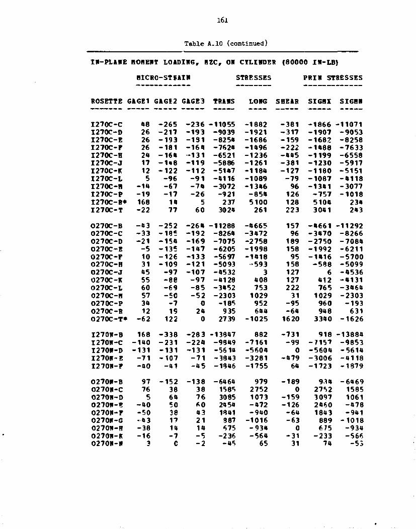
161
Table A.10 (continued)
IH-PLAHE ROBERT LOADIMG, HZC, OH CTLIHDEB (80000 IN-LB)
HICRO-STFAIW STBESSES PBIH STBESSES
ROSETTE G&GE1 GAGE2 GAGE3 TRAMS LONG SHEAR SIGHX SIGHR
I 2 7 0 C - C 08 - 2 6 5 - 2 3 6 -11055 - 1 8 8 2 - 3 8 1 - 1 8 6 6 - 1 1 0 7 1 I 270C-D 26 - 2 1 7 - 1 9 3 - 9 0 3 9 - 1 9 2 1 - 3 1 7 - 1 9 0 7 - 9 0 5 3 I 2 7 0 C - E 26 - 1 9 3 - 1 9 1 -8250 - 1 6 8 6 - 1 5 9 - 1 6 8 2 - 8 2 5 8 I 2 7 0 C - P 26 - 1 8 1 - 1 6 0 -7620 - 1 0 9 6 - 2 2 2 - 1 0 8 8 - 7 6 3 3 I 2 7 0 C - H 2a - 1 6 a • 1 3 1 - 6 5 2 1 - 1 2 3 6 - 0 0 5 - 1 1 9 9 - 6 5 5 8 I 2 7 0 C - J 17 - 1 * 8 - 1 1 9 -5886 - 1 2 6 1 - 3 8 1 - 1 2 3 0 - 5 9 1 7 I270C-K 12 - 1 2 2 - 1 1 2 - 5 i a 7 - 1 1 8 a - 1 2 7 - 1 1 8 0 - 5 1 5 1 I 2 7 0 C - L 5 - 9 6 - 9 1 -0116 - 1 0 8 9 - 7 9 - 1 0 8 7 - 0 1 1 8 I 2 7 0 C - H - 1 * - 6 7 - 7 a - 3 0 7 2 - 1 3 0 6 96 - 1 3 0 1 - 3 0 7 7 I 2 7 0 C - P - 1 9 - 1 7 - 2 6 - 9 2 1 - 8 5 a 126 - 7 5 7 - 1 0 1 8 I 2 7 0 C - B * 168 10 5 237 5100 128 510a 230 I 2 7 0 C - T - 2 2 77 6 0 3020 261 223 3001 203
O270C-B - 0 3 - 2 5 2 - 2 6 a -11288 - 0 6 6 5 157 - 0 6 6 1 - 1 1 2 9 2 O270C-C - 3 3 - 1 8 5 - 1 9 2 -8260 - 3 0 7 2 96 - 3 0 7 0 - 8 2 6 6 O270C-D - 2 1 - 1 5 a - 1 6 9 -7075 - 2 7 5 8 189 - 2 7 5 0 - 7 0 8 0 O270C-E - 5 - 1 3 5 - 1 0 7 - 6 2 0 5 - 1 9 9 8 158 - 1 9 9 2 - 6 2 1 1 O270C-F 10 - 1 2 6 - 1 3 3 -5697 - 1 0 1 8 95 - 1 0 1 6 - 5 7 0 0 O270C-H 31 - 1 0 9 - 1 2 1 - 5 0 9 3 •593 158 - 5 8 8 - 5 0 9 9 O270C-J 05 - 9 7 - 1 0 7 -0532 3 127 6 - 0 5 3 6 0270C-K 55 - 8 8 - 9 7 - 0 1 2 8 008 127 012 - 0 1 3 1 O270C-L 60 - 6 9 - 8 5 -3052 753 222 765 - 3 0 6 0 0270C-H 57 - 5 0 - 5 2 -2303 1029 31 1029 - 2 3 0 3 O270C-P 3a - 7 0 -185 952 - 9 5 960 - 1 9 3 O270C-B 12 19 20 935 600 - 6 0 908 631 O270C-T* - 6 2 122 0 2739 - 1 0 2 5 1620 3300 - 1 6 2 6
I 270H-B 168 - 3 3 8 - 2 8 3 -13807 882 - 7 3 1 918 - 1 3 8 8 0 I 2 7 0 B - C - m o - 2 3 1 - 2 2 a - 9 8 0 9 - 7 1 6 1 - 9 9 - 7 1 5 7 - 9 8 5 3 I 270R-D - 1 3 1 - 1 3 1 - 1 3 1 -5610 - 5 6 0 0 0 - 5 6 0 0 - 5 6 1 0 I 2 7 0 H - E - 7 1 - 1 0 7 - 7 1 -3803 - 3 2 8 1 - 0 7 9 - 3 0 0 6 - 0 1 1 8 I 2 7 0 H - P - a o - 0 1 - 0 5 -1906 - 1 7 5 5 60 - 1 7 2 3 - 1 3 7 9
O270H-B 97 - 1 5 2 - 1 3 8 -6060 979 - 1 8 9 910 - 6 0 6 9 O270H-C 76 38 38 1585 2752 0 2752 1585 0270W-D 5 6a 76 3085 1073 - 1 5 9 3097 1061 O270H-E - 0 0 50 60 2050 - 0 7 2 - 1 2 6 2060 - 0 7 8 O270H-P - 5 0 38 03 1801 - 9 0 0 - 6 0 1803 - 9 0 1 O270R-G - 0 3 17 2 1 987 - 1 0 1 6 - 6 3 889 - 1 0 1 8 O270W-H - 3 8 10 10 675 - 9 3 0 0 675 - 9 3 0 O270H-K - 1 6 - 7 - 5 -236 - 5 6 0 - 3 1 - 2 3 3 - 5 6 6 O270H-H 3 C - 2 - 0 5 65 31 70 - 5 3

162
Table A.10 (continued)
IR-PL&RE ROBERT LOADIRG, HZC, OR CYLIRDER (80000 IR-L3)
HICRO-STSAIR STRESSES PRIR STRESSES
ROSETTE GAGE1 GAGE2 G1GE3 TR&RS LOHG SHEAR SIGHX SIGHR
I31SC-B 31 -203 3 -4426 -391 -2738 992 -5810 I315C-C 7 -219 70 -3296 -766 -3848 2020 -6082 T315C-D - 1 4 -203 84 -2601 -1213 -3822 1977 -5792 I315C-F 3 - 8 3 - 1 9 -22*2 -590 -859 -224 -2607 I315C-H - 1 2 - 6 1 27 -1171 -696 -1433 518 -2386 T315C-J - 1 2 - 7 6 24 -1122 -682 -1336 452 -2255 I315C-K - 2 6 - 6 6 22 -951 -1058 -1177 173 -2182 I315C-L - 7 2 -129 24 -2236 -2822 -2046 -462 -4596 I315C-R - 7 6 -110 14 -2100 -2918 -1709 -751 -4267 I315C-P - 5 2 - 7 9 - 9 -1382 -2131 -930 -1068 -2944
0315C-B - 2 6 24 -199 -3816 -1917 2971 253 -5986 0315C-C - 4 5 2S -194 -3586 -2419 2969 23 -6028 0315C-D - 5 2 3e -261 -4834 -3007 3982 165 -8006 0315C-E - 7 1 33 -249 -4655 -3527 3761 -288 -7894 0315C-»* - 7 3 - 1 5 1 -247 -8662 -4796 1269 -4417 -9041 0315C-B - 7 3 24 -227 -4379 -3500 3350 -561 -7318 0315C-K - 5 9 29 -180 -3251 -2738 2779 -204 -5785 0315C-L - 5 6 39 -149 -2359 -2395 2496 119 -4873 03I5C-H - 4 2 43 -130 -1863 -1826 2309 465 -4154 0315C-P -m 39 - 8 5 -1002 -712 1646 796 -2510
I315R-B 108 -100 -103 -4580 1859 31 1859 -4580 I315R-C - 5 0 - 5 5 -100 -3353 -2507 604 -2192 -3667 I315R-D - 5 0 - 2 8 - 4 3 -1512 -1955 191 -1441 -2026 I315R-E - 2 1 - 1 9 . 5 -492 -787 -190 -399 -880 I315R-P - 9 - 1 9 10 -190 -338 -382 125 -653 I315R-R 8 3 - 2 3 253 64 268 - 1 2
0315R-B 50 - 3 3 -197 -5095 - 3 5 2185 778 -5908 0315R-C 57 - 1 4 - 2 8 -986 1425 193 1 M 1 -1001 0315R-D 26 - 1 2 26 284 862 -501 1151 - 5 0315R-E 5 - 1 9 31 254 219 -657 894 - 421 0315R-P 0 - 2 1 28 158 51 -657 763 -554 0315R-G 2 - 2 1 19 - 5 0 58 - 5 32 539 -530 0315R-H 0 - 1 9 17 - 4 8 - 1 2 -469 440 - 500 0315R-K 0 - 7 9 56 19 -?19 257 -182 0315R-R* - 5 1 0 - 5 - 4 3 -1541 63 - 4 0 -1544

163
Table A. 11 . Axial f&rce, TYr, on cy l inder
AXIAL POBCB LOADIRG, r i C . OM CYLIBDBB (10000 LB)
BICBO-STBAIB STBBSSBS PBIH STBBSSBS
•OSBTTE GAGE1 GIGE2 GAGB3 THAIS IOWG SHBAB SIGBI SIGHM
I -O-C-C - 5 2 2 10* -115 0 104 -115 I -O-C-0 5 1 * 21 776 373 - 9 5 797 351 I -O-C-B 9 26 2* 1085 609 32 1087 607 I -O-C-F 1 * 31 26 1239 798 64 1248 789 I-O-C-H 26 31 33 1381 1197 - 3 2 1387 1191 I -O -C-J 33 33 36 1*77 1440 - 3 1 1495 1422 I-O-C-K 33 33 33 1*2* 142* 1 1*25 1423 I -O-C-L* - 7 9 31 33 1*95 -1914 - 3 2 1496 -1914 I-O-C-H 31 33 33 1429 1355 0 1429 1355 I -O-C-P 33 33 33 . •23 142* 1 1*24 1422 I -O-C-S 26 28 29 1225 1147 - 3 1226 1147
O-O-C-B - 2 - 2 6 - 2 * -1090 -396 - 3 2 -394 - 1 0 9 1 O-O-C-C 5 - 2 * - 2 1 -991 -153 - 3 1 -152 -992 0-O-C-D 12 - 2 1 - 2 1 - 9 * 8 7* - 1 74 - 9 * 8 O-O-C-B 17 - 2 * - 2 * -1056 184 - 1 184 -1056 O-O-C-F 17 - 2 6 - 2 1 -1057 18* - 6 3 188 -1060 O-O-C-H 21 - 2 6 - 2 8 -1218 27fc 32 279 -1219 O-O-C-J 24 - 3 1 -28 -1325 315 - 3 2 319 -1325 0-O-C-K 26 - 2 8 - 3 1 -1327 389 32 389 -1327 0-O-C-L 29 - 3 1 - 3 1 -1382 «*3 A 443 -1382 O-O-C-H 26 - 3 1 - 3 3 -1*32 356 32 357 - 1 * 3 3 0-O-C-P 26 - 3 1 - 3 1 -1380 372 0 372 -1380 0-O-C-S 17 - 2 8 - 3 5 -1422 77 95 82 - 1 * 2 8
I - O - I - B 29 - 3 1 - 2 1 -118* 512 -128 522 -1193 I-O-I I -C 3 - 3 1 -26 -1262 - 3 0 1 -64 -297 -1266 I-O-S-D - 2 - 2 * -2ft -10*8 -331 0 -381 - 1 0 * 8 I -O-B-E - 2 - 19 -19 -837 -318 - 1 -318 -837 I -O- l l -F 0 - I B - 1 9 -732 -216 65 -208 - 7 * 0 I - O - B - i 0 0 - 2 - * 5 - 9 ZZ 9 - 6 3
O-O-B-B 12 - 1 2 - 7 - * 2 6 230 - 6 3 236 -432 0-O-W-C 12 5 7 25* 436 -31 441 2*8 0-O-B-D 5 12 12 511 291 - 1 511 291 0-O-B-B 0 12 9 466 136 31 469 133 0-O-B-P 0 9 9 413 120 1 413 120 0-O-W-H - 2 7 5 261 4 32 265 0 0-O-B-K -5 0 0 4 - 1 * 7 0 4 - 1 * 7 0-O-B-B* - 5 - 5 - 8 8 -2043 -758 1113 -116 -2685

161
Table A.II (continued)
AXIAL PORCE LOADIBG, PXC, OB CTLIMDER (10000 IB)
HICRO-STfiAIfl STRESSES PRIW STRESSES
ROSETTE GAGE1 GAGE2 GAGE3 TRASS LOWG SHEAR SIGHX SIGRB
I - 9 0 C - B - 1 0 112 115 4998 1201 - 3 3 4999 1201 I - 9 0 C - C * 12 81 0 1769 878 1080 2402 155 I - 9 0 C - D 16 64 67 2860 1352 - 3 2 28b 1 1351 I - 9 0 C - E 19 55 59 2487 1309 - 6 4 2490 1305 I - 9 0 C - P * 21 116 52 367* 1737 846 3992 1420 I - 9 0 C - B - 5 6 43 40 1886 - 1 1 0 0 33 1886 - 1 1 0 0
O-90C-B - 1 9 31 19 1108 - 2 4 2 157 1126 - 2 6 0 O-90C-C - 2 6 19 17 808 - 5 4 4 31 808 - 5 4 5 O-90C-D - 3 1 17 1 * 706 - 7 1 7 33 707 - 7 1 8 O-90C-E - 3 6 1« 17 714 - 8 5 7 - 3 2 715 - 8 5 8 O-90C-P - 3 8 17 17 769 - 9 1 1 0 769 - 9 1 1 O-90C-B* 1 * 64 66 2 8 * 1 1276 - 2 8 2841 1275
I - 9 0 B - B • 5 62 67 2778 2182 - 6 3 2784 2176 I - 9 0 B - C 21 26 31 1232 1011 - 6 3 1249 994 I - 9 0 B - D 2 17 10 575 247 96 601 221 I - 9 0 B - E - 5 1 * 10 529 13 63 537 6 I - 9 0 B - P * 33 33 33 1U25 1423 1 1425 1423 I - 9 0 B - B 9 5 5 193 340 0 340 193
O-901-B - 5 5 - 1 4 - 1 9 - 6 7 3 - 1 8 4 3 63 - 6 7 0 - 1 8 4 6 0 - 9 0 1 - C - i l - 2 * - 2 9 - 1 1 2 8 - 9 8 2 64 - 9 5 8 - 1 1 5 2 O - 9 0 I - D - 7 - 2 4 - 2 1 - 9 8 7 - 5 1 4 - 3 1 - 5 1 2 - 9 8 9 O-901 -E - 7 - 1 7 - 1 7 - 7 2 6 - 4 3 7 0 - 4 3 7 - 7 2 6 O-90B-P - 7 - 1 * - 1 7 - 6 7 4 - 4 1 9 31 - 4 1 6 - 6 7 8 O - 9 0 B - I - 5 - 5 - 5 - 2 0 8 - 2 0 8 0 - 2 0 8 - 2 0 8

165
Table A.11 (continued)
AXIIL POBCE LOIDIMG, PIC, OH CTLIHOBB f10000 LB)
RICRO-STBUW STRESSES PRII STRESSES
ROSETTE GIGE1 G16I2 G&GB3 TBAHS LOBG SHEtB SIGH! SIGBB
I180C-B 0 - 1 0 - 1 0 -431 -139 - 2 -139 - 4 3 1 I180C-C n 9 11 444 265 - 3 3 450 258 I180C-D 4 18 21 858 383 - 3 2 860 381 I180C-B 11 21 23 953 629 - 3 1 956 626 I180C-F 16 26 28 1158 834 - 3 1 1161 831 I180C-S 35 16 13 604 1217 32 1219 602
O180C-B 2 - 2 0 - 2 4 -968 -243 61 -238 - 9 7 3 O180C-C 9 - 1 7 - 1 7 -772 26 3 26 - 7 7 2 O180C-D 13 - 1 5 - 1 7 -712 185 29 186 - 7 1 3 O180C-E 21 - 1 7 - 1 7 -777 385 - 1 385 - 7 7 7 O180C-P 21 - 2 2 - 1 9 -917 363 - 3 2 363 - 9 1 8 O180C-S 20 - 2 2 - 1 7 -863 328 - 6 4 332 - 866
I180H-B 29 - 2 6 - 3 8 -1441 431 160 444 -1454 I180H-C 0 - 2 1 - • 0 -1358 -404 254 -340 -1421 I180H-D - 7 0 - 3 1 -668 -4 12 414 -107 -973 118OH-E - 5 - 1 9 - 3 1 -1090 -456 160 -428 - 1 1 2 9 I180H-F 0 - 1 5 - 1 9 -739 -232 6 1 -225 -746 I180R-H - 5 - 2 - 2 - 9 3 -167 1 - 9 3 - 1 6 7
O180H-B 9 0 - 1 0 -220 216 127 251 -254 O180H-C 14 17 9 555 592 95 670 477 O180R-D 7 17 17 720 426 - 1 720 426 O',80H-E 2 U U 623 254 - 1 623 254 C180J-P 0 12 14 574 1 7 i - 3 2 576 168 0180H-H - 3 - 2 - 2 -107 -107 0 -107 -107

166
Table A.11 (continued)
1XI&L FOECE LOADIHG, F I C # OB CTLIRDEB (10000 LB)
HICBO-STBUR STBESSES PBIB STBESSES
BOSETTE G1GB1 GAGE2 GAGE3 TB1BS LOWG SHEAR SIGRX SIGBI
I 2 7 0 C - C 7 77 72 3252 1197 64 3254 1195 I 270C-D 15 60 57 2563 1204 33 2563 1204 I 2 7 0 C - E 14 5* 52 2326 1117 31 2327 1116 I 2 7 0 C - P 19 50 47 2117 1054 32 2118 1054 I 2 7 0 C - H 14 • 5 35 1749 943 127 1769 923 I 2 7 0 C - J 7 • 5 33 1710 718 158 1734 693 I270C-K 0 40 31 1562 463 126 1576 449 I 2 7 0 C - L - 1 9 41 28 1546 - 1 1 5 168 1563 - 1 3 2 I270C-H - 3 1 33 31 1434 - 5 1 2 31 1434 - 5 1 3 I 2 7 0 C - P - 5 2 40 24 1467 - 1 1 3 2 224 1487 - 1 1 5 1 I270C-B - 5 8 33 33 1528 - 1 2 8 3 2 1528 - 1 2 8 3 I 2 7 0 C - T 19 14 21 744 794 - 9 6 868 670
O270C-B - 1 5 24 26 1102 - 1 0 8 - 3 0 1103 - 1 0 8 O270C-C - 1 9 21 24 1002 - 2 7 9 - 3 2 1003 - 2 8 0 O270C-D - 2 * 19 23 956 - 4 3 6 - 6 1 958 - 4 3 9 O270C-E - 2 9 16 21 856 - 6 0 9 - 6 3 858 - 6 1 1 O270C-F - 2 9 19 19 856 - 6 0 9 0 856 - 6 0 9 O270C-H - 3 1 19 21 908 - 6 6 6 - 3 1 909 - 6 6 6 O270C-J - 2 9 21 21 955 - 5 8 1 - 1 955 - 5 8 1 O270C-K - 2 4 24 26 1112 - 3 8 9 - 3 1 1113 - 3 9 0 O270C-L - 1 5 31 40 1569 33 - 1 2 8 1579 23 O270C-H - 1 40 42 1800 514 - 2 9 1801 513 O270C-P 13 49 49 2147 1041 - 2 2147 1041 O270C-B 18 49 47 2096 1174 32 2097 1173 O270C-T* - 4 9 21 0 506 - 1 3 1 6 274 546 - 1 3 5 6
I 270B-B 38 76 69 3153 2088 95 3162 2 079 I270N-C 29 41 40 1750 1381 1 1750 1381 I 270B-D 9 24 24 1037 594 0 1037 594 I 2 7 0 B - E 0 31 17 1047 311 191 1094 264 I 2 7 0 B - P - 2 17 14 683 130 32 685 129
O270W-B - 5 9 - 1 7 - 1 2 - 5 5 7 - 1 9 4 2 - 6 3 - 5 5 4 - 1 9 4 5 O270B-C - 2 6 - 2 6 - 2 6 - 1 1 1 5 - 1 1 1 5 0 - 1 1 1 5 - 1 1 1 5 O270W-I* - 7 - 2 2 - 2 2 - 9 4 2 - 5 0 4 1 - 5 0 4 - 9 4 2 O270B-B 0 - 1 7 - 1 9 - 7 9 3 - 2 4 4 31 - 2 4 3 - 7 9 5 O270B-P - 3 - 1 5 - 1 5 - 6 3 9 - 2 7 3 1 - 2 7 3 - 6 3 9 0270B-G 0 - 1 2 - 1 2 - 5 2 7 - 1 6 2 0 - 1 6 2 - 5 2 7 O270B-H 0 - 1 2 - 1 2 - 5 3 3 - 1 6 8 0 - 1 6 8 - 5 3 3 O270H-K 0 —* - 7 - 2 7 3 - 9 2 31 - 8 7 - 2 7 8 O270B-B - 5 - 3 - 3 - 1 1 4 - 1 8 8 0 - 1 1 4 - 1 8 8

iCl
Table A.II (continued;
AXIAL FORCE LOADIHG, FIC, OR CTLIBDBt (10000 LB)
niCRO-STRAIR STRESSES PRIB STRESSES
ROSETTE GAGE1 GAGE2 GAGE3 TRABS LOIG SBBAB SIGRX SIGHR
I315C-B - 2 • 5 • 3 1939 508 33 19*0 508 I315C-C 9 «8 31 1715 798 223 1767 7 * 7 I315C-D 12 • 7 21 1*92 806 3*3 163* 6 6 * I315C-F 1« 29 26 1186 782 32 1188 779 I315C-B 2 * 31 21 1120 1048 128 1217 951 I315C-J 26 31 19 1066 1103 159 1245 925 I 3 1 5 C - I 26 31 17 1015 1087 191 12*5 857 I315C-L 29 38 2 860 1119 • 8 5 1*92 «87 I315C-B 28 • 1 - 1 0 650 10*6 672 15*9 1*7 I315C-P 19 • 6 - 3 2 285 6 * 1 1028 1506 - 5 8 0
0315C-B - 1 0 - * 3 38 - 9 8 -318 -1075 872 -1288 0315C-C - 7 - • 0 38 - • 8 - 2 3 1 - 1 0 * 2 907 -1186 0315C-D - 2 - • 5 52 156 - 2 7 -12S6 136* -1235 0315C-B 0 - • 5 • 7 • 9 13 -1233 126* -1202 0315C-F* - 2 -119 • 7 -15€5 - 5 * 3 -2213 1217 -3326 0315C-B 0 - • 1 40 - 1 * - 1 7 -1075 1059 - 1 0 9 0 0315C-K 2 - 3 1 38 1*2 103 -915 1038 -793 0315C-L 11 - 3 1 35 7 * 365 -885 1116 - 6 7 7 0315C-B 19 - 1 9 38 385 676 -760 130* - 2 * 3 0315C-P 31 0 50 1045 1229 -666 1809 * 6 5
I315B-B 31 5 36 854 1181 - * 1 3 1*62 5 7 * I315W-C 1« 0 1 * 289 510 -190 619 180 I315B-D 5 0 0 - 1 8 131 0 131 - 1 8 I315B-E 0 « - 3 39 2 9 * 116 - 7 5 I315B-F 0 9 - 3 1 M 3 * •i58 257 - 7 9 I315B-B 0 0 0 - 2 0 7 - 1 7 - 2 0
0315B-B - 2 5 - 3 1 19 -242 -830 -667 192 - 1 2 6 * 0315B-C - 7 - 1 5 2 -262 -300 -223 - 5 7 - 5 0 5 0315B-D 0 - 7 0 -158 - 5 0 - 9 3 3 - 2 1 2 0315R-B 0 - 2 - 2 -105 - 3 4 1 - 3 * - 1 0 5 0315B-F - 2 - 2 - 2 -105 -106 0 -105 -106 0315B-G - 2 0 - 2 - 5 * - 9 1 31 - 3 7 - 1 0 8 03151-B - 2 - 2 - 5 -155 -121 31 -102 - 1 7 * 0315R-K - 2 0 - 5 -106 -105 63 - * 2 - 1 6 8 0315B- I * - 3 6 0 0 35 -1078 0 35 -1078

168
Table A.12. In-plane force, F v _ , on cylinder
IN-PLANE FORCE LOAEIRG, FTC, ON CYLINDER (3000 LB)
HICRO-STBAIN STRESSES PRIN STRESSES
ROSETTE GAGE1 GAGE2 GAGE1 TRANS LONG SHEAR SIGHX SIGHN
I-O-C-C -2 33 33 1»70 370 0 1470 370 I-O-C-D -12 10 10 4 32 -228 0 432 -228 I-O-C-E -31 2 0 86 -904 32 87 -905 I-O-C-F -45 _c -5 -160 -1408 0 -160 -1408 I-O-C-H -79 -12 -10 -38S -2477 -32 -385 -2478 I-O-C-J -98 -12 - m -469 -3075 32 -469 -3075 I-O-C-K -103 -17 -12 -516 -3232 -64 -515 -3234 I-O-C-L* -177 -14 _c -226 -5367 -127 -223 -5370 I-O-C-H -98 -12 -7 -312 -3030 -64 -311 -3031 I-O-C-P -91 -2 -12 -21S -2786 127 -209 -2792 I-O-C-S -72 -2 -7 -131 -2188 64 -129 -2190
O-O-C-B -26 10 12 597 -610 33 598 -611 O-O-C-C -45 0 _c -66 -1377 63 -63 -1380 O-O-C-D -6 2 -10 -10 -358 -1966 1 -358 -1966 O-O-C-E -69 -12 -10 -407 -2195 -29 -407 -219* O-O-C-F -79 -7 -12 -341 -2461 63 -339 -2463 O-O-C-H -90 -10 _c -226 -2780 -63 -225 -2782 O-O-C-J -102 2 -5 46 -3059 97 49 -3062 O-O-C-K -102 fl 2 151 -3025 -31 151 -3025 O-O-C-L -107 4 2 262 -3136 31 26 2 -3136 o-o-c-n -100 2 a 253 -2923 -32 254 -2923 0-0-C-P -88 2 0 137 -2603 33 137 -2603 0-0-C-S -7 2 0 7 222 -2082 -95 226 -2096
I-O-R-B 31 91 86 3861 2093 64 3863 2090 I-O-N-C 38 65 *5 2590 1927 128 2614 1903 I-O-H-D 24 ue «•€ 2027 1327 32 2028 1325 I-O-R-E 19 41 38 1716 1090 32 1718 1088 T-O-R-F 17 31 38 1508 955 -96 1524 939 I-O-R-R 2 0 0 -3 71 0 71 -3 O-O-R-B -3 -5 -12 -373 -190 94 -150 -413 O-O-R-C 19 -34 -3tt -1497 110 -1 110 -1497 O-O-R-D 26 -33 -31 -1446 339 -33 340 -1447 O-O-R-E 26 -29 -20 -1183 419 -64 421 -1186 O-O-R-P 26 -26 -22 -1081 449 -62 451 -1084 O-O-R-H 26 -10 -12 -505 624 32 625 -506 O-O-R-K 16 5 2 132 526 31 528 130 O-O-R-R* 2 h 87 1998 663 -1094 2612 49
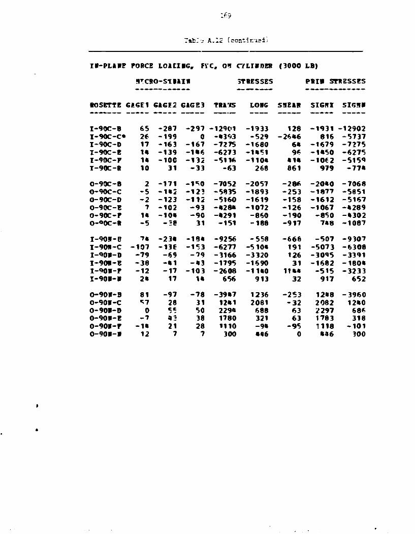
Tab:.- A. 12 (ccr-tir.-i?d/
IB-PL*HP FORCE LOACI1G, FVC, 0 1 C7LT1DEB (3000 LB)
STC80-STBAI1 3T BESSES PRIB ST1ESSES
BOSETTE 6A6E1 GAGE2 GAG 2 3 TRA'iS LOIG SHEAR SIGRZ SIGH!
I-90C-B 65 -287 -297 -12901 -1933 128 -1931 -12902 I-90C-C* 26 -199 0 -•393 -529 -26B6 816 -5737 I-90C-D 17 -163 -167 -7275 -1680 6« -1679 -7275 I-90C-E IB -139 -1B6 -6273 -1B51 96 -1B50 -6275 I-90C-F IB -IOC -132 -5116 -110* • IB -1062 -5159 I-90C-R 10 31 -33 -63 268 861 979 -77* 0-90C-B 2 -171 -1*0 -7052 -2057 -286 -20*0 -7068 O-90C-C -5 -1B2 -123 -5835 -1893 -253 -1877 -5851 O-90C-0 -2 -123 -112 -5160 -1619 -158 -1612 -5167 0-90C-E 7 -102 -93 -•28* -1072 -126 -1067 -•289 0-90C-F IB -10B -90 -•291 -860 -190 -850 -•302 O-OOC-R -5 -•8 31 -151 -188 -917 7»8 -1087 I-901-B 7« -23B -18B -9256 -558 -668 -507 -9307 I-901-C -107 -136 -153 -6277 -51 OB 191 -5073 -6308 I-90B-D -79 -69 -79 -3166 -3320 126 -3095 -3391 I-901-E -38 -•1 -•3 -1795 -1690 31 -1682 -180B I-90B-F -12 -17 -103 -2608 -11B0 11BB -515 -3233 I-90I-1 2« 17 IB 656 913 32 917 652 0-901-3 81 -97 -78 -39B7 1236 -253 12«8 -3960 0-90I-C *7 28 31 12«1 2081 -32 2082 12B0 0-901-0 0 ce 50 229* 688 63 2297 686 0-901-E -7 • 3 38 1780 321 63 1783 318 0-901-F -IB 21 28 1110 -9B -95 1118 -101 0-901-1 12 7 7 300 •46 0 «»6 300

170
Table A.12 (continued!
H - P I M E FORCE L01CI1G, FTC, OS CTLIHDER (3000 LB)
OTCSQ-STBAIR SfRESSBS P R I l STRESSES
ROSETTE GAGE* GAGE2 GAGE3 TRAWS LORG SHEAR SIGRI SIGH!
I 1 8 0 C - B - 5 92 68 3528 917 31ft 3566 880 I 1 8 0 C - C - 2 • 2 26 1505 381 220 15«7 339 I 1 8 0 C - D - 2 1 19 2 »90 - * 9 0 220 537 - 5 3 7 1-180C-E - • 2 K - 7 - 5 -1275 157 1ft - 129 f t neoc-p . C O - 2 - 1 2 -2f t6 - 1 8 » 2 126 - 2 3 6 - 1 8 5 2 I I 8 0 C - S - 1 * 1 - 2 - 1 2 - 1 * 5 -ft 570 126 - U 2 - « 5 7 »
O180C-B - 2 6 12 22 768 -5ft8 - 1 2 6 "»80 - 5 6 0 O180C-C - 5 0 „ K 3 11 - 1 * 8 7 - 9 6 18 -1 f t93 O180C-D - 6 9 -1ft - 7 - 3 9 0 -2178 -9ft - 3 8 5 - 2 1 8 3 O180C-E - 9 3 - 1 6 - 1 2 - 5 3 0 - 2 6 5 0 - 6 3 - 5 2 8 - 2 6 5 2 O180C-F - 1 0 5 -2ft - 1 7 - 7 7 3 - 3 3 7 1 - 9 5 - 7 7 0 -337 f t O180C-S* 0 12 - 1 0 52 16 285 320 - 2 5 2
I 1 8 0 1 - B 12 97 117 •696 1761 - 2 5 7 • 709 1729 I 1 8 0 R - C »C 5ft 8 1 2929 2086 - 3 5 0 3056 1959 I 1 8 0 R - D * 28 2 59 1316 12«3 - 7 6 * 204ft 515 I 1 8 0 R - E 2» ft3 6ft 2317 1O01 - 2 8 9 2000 1318 I 1 8 0 R - P 2 1 3« «2 1*86 11«3 - 9 * 1702 1127 T180R-R 2 - 1 0 - 2 2 55 - 2 55 - 2 2
0180R-B _«; - 1 9 - 1 7 - 7 7 « - 3 7 5 - 2 9 - 3 7 3 - 7 7 6 O180R-C 2 1 - 5 C - f t3 - 2 0 6 1 2ft - 9 5 28 - 2 0 6 6 O180R-0 26 - * 8 - 5 0 - 1 9 6 2 1 % 158 208 -197 f t O1P0J-E 31 - 3 1 - 3 2 - l e « 5 a 9« 32 090 -1ftft5 O180R-P 29 - 2 1 - 3 1 - 1 1 8 1 502 127 511 - 1 1 9 0 O180H-R 0 2 2 105 31 0 105 31

IR-PLARE FOPCE LOACIRG, FTC, OI CTLIRDE3 (3000 LB)
MCRO-STFAIR STRESSES M I ! STRESSES
ROSETTE GAGE1 GAG52 GACE3 TRARS LORG SHEAR SIGfll SIGfll
I270C-C 28 - 2 0 1 -177 -83R5 -1665 -319 -1650 -8360 I270C-0 11 - 168 -1«€ -69 \7 -1735 -?89 -1719 -6928 I270C-5 15 - IRS -133 -621? -1399 -220 -1388 -6222 I270C-F 15 - I R S -121 -57 9 i -1270 -287 -1256 -5810 I270C-H 15 - 1 3 3 - 9 2 - •957 -1028 - 5 39 -956 -5029 I2"»0C-J 18 - 1 2 3 - 9 2 -0521 -%22 -503 -70« - • 5 9 9 I270C-R 18 -10? - 7 C -3901 - * 3 i -512 - K 5 » - • 0 1 8 I270C-1 28 - 9 6 - 5 3 -3308 -159 -566 - 6 0 - 3 * 0 7 I270C-B 20 - 8 3 - 3 7 -2650 -190 -607 - 5 2 -2792 T270C-P 10 - 5 5 11 -978 1 - 8 8 1 521 -1»98 I270C-R 12 - 3 £ 31 -171 308 -926 102» -888 I270C-T - 3 6 57 06 2303 -387 160 2312 -396
O270C-B - 1 9 - 1 6 2 -183 -7560 -2839 285 -2822 -7577 O270C-C - 1 2 - 1 1 7 -138 -5578 -2030 285 -2008 -5601 O270C-D - 2 - 9 7 -120 - •857 -1529 3«9 -1«93 - • 8 9 3 O270T-E 7 - 8 6 -112 - • 3 * 5 -1090 3*9 -1053 - • 3 8 2 O270C-F 17 - 8 1 -100 -3990 -698 253 -678 - • 0 0 9 O270C-H 31 - 7 1 - 9 5 -3692 -180 317 -152 -3720 O270C-J 36 - 6 « - 9 0 -3«J6 39 309 7» -3«71 O270C-K 38 - 5 7 - 9 3 -333« 101 • 7 « 205 -3398 O270C-L 31 - 3 8 - 9 5 -2960 39 760 221 -3102 O270C-H 26 - 2 6 - 7 8 -2373 81 665 250 -25»1 O270C-P 15 10 - 5 5 -999 139 857 598 -1058 O270C-R 0 36 - 3 3 61 27 919 963 - 876 O270C-T* - 2 6 112 0 2092 - 2 5 1090 3187 -720
I2701-B 88 -206 -212 -10168 -«01 - • 0 5 - 3 8 1 -10189 I270R-C -100 -165 -160 -7020 -5115 - 6 0 -5113 -7026 I270R-D - 8 8 - 9 3 - 9 3 -3995 -3808 0 -3808 -3995 I270R-E - 0 5 - 8 8 - 5 3 -30»5 -2270 -077 -2046 -3273 I270R-F - 2 3 - 3 3 - 3 6 -1500 -J 100 32 -1137 -1502
0270W-E 87 - 8 3 - 8 3 -3750 1095 - 2 1095 -3750 O270R-C 59 35 38 1500 2236 - 3 1 2237 1502 O270R-0 10 52 57 2395 1000 - 6 3 2397 1001 O270R-E - 2 1 • 0 05 1906 - 7 1 - 6 3 1908 - 7 3 O270R-F - 2 9 31 36 1095 -008 - 6 3 1097 -010 O270R-G - 2 0 19 19 863 -055 0 863 -055 O270R-H - 2 0 12 10 601 -533 - 3 2 602 -530 O270R-K -m 0 2 68 -008 - 3 2 70 - 010 0270R-R 2 2 2 102 102 0 102 102

172
Table A.12 'continued)
II-PLAIE PORCS LOltlRG, FTC, 09 CT LI IDES (3COO LB)
SICIO-STFAIB STRESSES PBII STRESSES
ROSETTE GAGE1 GAGE2 GAG£"» T H I S LOK SHEAR SIGHZ SIGHR
I315C-B 19 - 1 M - 1 0 -3 *31 -S57 -1686 300 -0192 £315C-C 2 -155 31 -2731 -708 -2081 933 -ftft11 I315C-0 -1ft -Iftft ft* -21*3 -1073 -2517 966 -ft181 I315C-F - 7 - 6 2 - 2 1 -1928 -763 -5ft1 -537 -2055 I315C-H - 1 7 - 6 " 10 -1136 - 8 * 2 -95« - 2 3 -1955 I315C-J - 1 9 12 -923 -850 - 8 9 1 5 -1778 X315C-K - 2 6 - • P 10 - 7 * -1000 -827 - 1 3 -1693 I315C-L - *« ; - 8 * 31 - 103 i -2206 -1097 - 2 0 - i ' 5 5 I315C-H -6 9 - 6C 29 -607 -2262 -1179 6 - 2 8 ?5 I315C-P - 5 7 - » 1 26 -25? -1797 -892 155 -2205
0315C-B -1ft 3? -138 -2278 -1110 2276 655 - • 0 * 3 0315C-C - 2 8 36 -133 -2106 -1*96 22 ft* 069 - * 0 6 1 0315C-D - 3 3 • 5 -183 -2987 -1S92 3030 603 -5523 0315C-E - 5 0 03 - 171 -2760 -2323 2800 311 -5390 0315C-P - 5 0 38 -168 -2812 -2338 2750 185 -5335 0315C-H* 0 33 -150 -2658 -798 2097 936 -0392 0315C-K - « 5 33 -1C9 -1608 -2119 1896 50 -3777 0315C-L - 5 2 5C - 8 5 -725 -1783 1801 620 -3131 0315C-B - 5 2 03 - 6 9 -516 -1720 1085 085 - 2721 0315C-P - 5 5 36 - 0 0 - « 0 -1650 1011 000 -2138
I315R-B 57 - 6 2 - 7 9 -3163 772 223 785 -3175 I315R-C - 3 8 - 3 3 - 6 7 -2165 -1797 006 -1099 -2063 I315R-0 - 3 3 - 1 9 - 2 6 -962 -1293 96 -936 -1313 I3?5W-E - 1 » - 1 2 - 2 -299 -520 -127 -201 -S78 I315R-F - 5 - 1 2 7 -100 -173 -255 121 -390 I315R-H* - 2 2 -069 -10256 -3108 6283 516 -13920
0315R-B 05 •J -133 -3073 030 1707 1120 -3767 0315R-C 03 c - 1 0 -255 1200 253 1207 -298 0315W-D 17 -ft 17 257 580 -287 751 91 0315R-E 5 - 9 21 259 230 -012 656 -167 0315R-P 1 - 1 1 17 120 58 -370 066 -280 0315R-G 3 - 1 1 15 75 112 -301 035 -208 031*i!l-H 3 - 9 12 65 107 -282 369 -197 0315R-K 3 - 0 ft 70 108 -159 251 - 6 9 0315R-R - 0 2 3 3 170 -1193 0 170 -1193

Table A.13. Out-of-plane force, F__, on cyl inder
OOT-OF-FLASB FOBC1 LOADIBG, FIC, Ol CTLIIDBB (3000 LB}
BICBO-STBAIB STBESSES PBII STBESSES
BOSBTTB GAGE1 GAGI2 GKCE3 TUBS LCIG SBEAB SIGHI SIGBB
I-O-C-C -2 -•5 31 -312 -165 -1017 781 -1258 I-O-C-D 0 -60 41 -419 -126 -1335 1070 -1615 I-O-C-B 0 -52 38 -315 -9* -1208 1006 -1417 I-O-C-F 0 -50 38 -2*2 -79 -1176 1009 -1350 I-O-C-B -2 29 -•5 -36* -181 985 717 -1262 I-O-C-J -2 26 -•3 -36* -181 922 654 -1199 I-O-C-R 2 -•1 21 -422 -55 -826 608 -1085 I-C-C-L* -138 -•3 21 -320 -4249 -859 -141 -4428 I-O-C-B -2 -•1 26 -312 -165 -890 655 -1132 I-O-C-B -5 -3€ 29 -152 -189 -859 688 -1029 I-O-C-S -7 -3€ 26 -202 -275 -827 589 -1066
O-O-C-B 0 5* -4 5 204 57 1328 1460 -1199 O-O-C-C 2 5* -«o 302 158 1264 1497 -1035 O-O-C-0 -3 59 -43 361 31 1359 1566 -1173 O-O-C-B 0 57 -•3 30* 85 1329 1527 -1139 O-O-C-F 5 52 -•5 1M 178 1295 1457 -1134 O-O-C-B -3 50 -36 307 15 1138 1308 -986 O-O-C-J 2 •5 -33 249 137 1045 1239 -853 O-O-C-B -3 42 -33 202 -18 1011 1109 -925 O-O-C-L 0 42 -29 305 83 948 1148 -760 O-O-C-B -3 40 -2€ 307 14 884 1057 -736 O-O-C-P -3 38 -31 151 -33 917 981 -863 O-O-C-S -5 • 0 -29 257 -74 917 1023 -840
I-O-B-B -5 -12 -19 -679 -347 96 -322 -705 I-O-B-C -12 0 -17 -355 -•66 223 -180 -641 I-O-I-D -1C 0 -1C -200 -347 128 -126 -421 I-O-B-B -7 _c -2 -150 -261 -32 -141 -269 I-O-l-F -5 _c 0 -100 -174 -64 -63 -211 I-O-l-B 0 0 0 0 0 0 0 0 O-O-l-B 0 19 -17 «5 8 474 500 -447 O-O-l-C -3 2 2 96 -49 -1 96 -49 O-O-l-D -3 -5 9 100 -48 -191 230 -178 O-O-l-B -3 -7 7 -3 -78 -190 153 -234 O-O-l-P -3 -3 7 100 -47 -126 172 -120 O-O-l-B 0 -7 7 -5 -6 -189 184 -195 O-O-l-B 2 0* -59 46 -95 102 -115 O-O-l-B 0 0 -1 -21 -12 8 -7 -26

nh
Table A.13 (continued)
OOY-OP-PLiBB POBCE LOiDIBG, PZC„ OB CTLIBDBB (3000 LB)
•ICBO-STB1IB STIBSSIS PBIB STIESSES
BOSBTTB GIGE1 G1GE2 GIGE3 TB1BS LOIG SHEIB SIGHI SIGHH
I-90C-B -5 43 -10 735 70 701 1178 -373 I-90C-C* -3 62 0 1366 331 B26 1823 -127 I-90C-D -5 64 -3€ 627 39 1339 1V04 -1038 I-90C-B -10 62 -3* 631 -106 1275 1590 -1065 I-90C-P -10 65 -29 812 -51 1257 1710 -949 I-90C-B -24 96 83 1013 477 192 4023 466 O-90C-3 7 -17 47 66U «03 -854 1395 -333 O-90C-C 5 -36 62 568 313 -1296 1743 -062 O-90C-D* 2 -33 -1*7 -3965 -1119 1517 -461 -4622 0-90C-B 0 -33 62 626 188 -1265 1690 -877 0-90C-F -2 -28 69 869 196 -1296 1484 -799 O-90C-H -43 93 102 4322 16 -126 4326 12 I-90B-B -10 -12 -17 -619 -472 64 -448 -642 I-90B-C -10 -17 -2 -*09 -409 -191 -218 -600 I-90B-D 0 -7 0 -158 -47 -95 8 -212 I-90B-B 0 0 -5 -107 -36 63 1 -144 I-90B-P* 21 -41 2 •862 385 -572 608 -1085 I-90B-1* -22 -12 -12 -518 -811 0 -518 -811 0-9CB-B -5 -9 36 631 47 -632 1035 -358 O-90B-C 0 0*
~4 0 - 52 -16 -32 3 -70 O-90W-D 2 2 -12 -211 8 190 117 -321 O-90I-E 4 7 -7 -15 124 189 256 -147 0-90B-F a 4 -7 -68 112 157 203 -159 O-90B-!i 2 0 2 38 75 -32 93 20

175
Table A.13 (continued}
OOT-OP-PL1IE POBCf L O i D I K , MC, OB CTLXBOBB (3000 IB)
B1CBO-S1BAIB STBESSBS PBII STBESSES
10SETTS GIGI1 G1GI2 GIGE3 TB&SS LOBG SHEIB SIGHX SIGHB
I180C-B 2 -26 33 1*2 106 -787 911 -663 I180C-C 2 -52 *7 -119 28 -1321 1278 -1368 I160C-D 2 -55 • 7 -171 8 -1351 1273 - 1 * 3 5 I180C-B 2 -57 «2 -327 -35 -1319 11*6 -1509 I180C-P 2 - 52 37 -325 -33 - 1 1 9 * 102* -1382 I180C-S - 1 -29 28 -22 -24 - 7 5 * 732 -777
0180C-B 5 55 - * 5 196 196 1331 1529 - 1 1 3 * 0180C-C 5 -«S 196 195 1333 1528 -1137 0180C-D 5 59 -50 200 196 1*58 1656 -1261 0180C-B 5 55 - * 6 1*6 180 136* 1527 -1200 0180C-P 0 50 -5C 0 0 133(0 1330 -1330 0180C-S» 0 26 - 3 € -209 -63 82* 691 -963
I180H-B - 2 - 2 -12 -309 -163 128 - 8 9 - 3 8 3 I180B-C - 2 0 -7 -153 -116 95 - 3 7 -232 J180I-D 0 - 2 - 7 -203 -61 6* - 37 - 2 3 1 I169V-E 2 2 4. 1J* 104 0 10* 10* I180B-P 2 0 7 1 M 106 - 9 6 222 28 I180R-B 0 0 0 3 2 0 3 2
018QB-B -10 16 • c 265 -206 281 397 Zil 0180B-C - 5 _ e 2 - * 7 -157 - 9 5 8 -212 0180V-D - 5 - i * 2 -256 -219 -222 - 1 5 - * 6 0 0180B-B - 2 - I B 7 - 1 5 * -118 -285 150 - * 2 2 0180B-P 0 -12 7 -104 - 3 1 -253 188 - 3 2 * 0180B-B 0 0 0 0 0 0 0 0
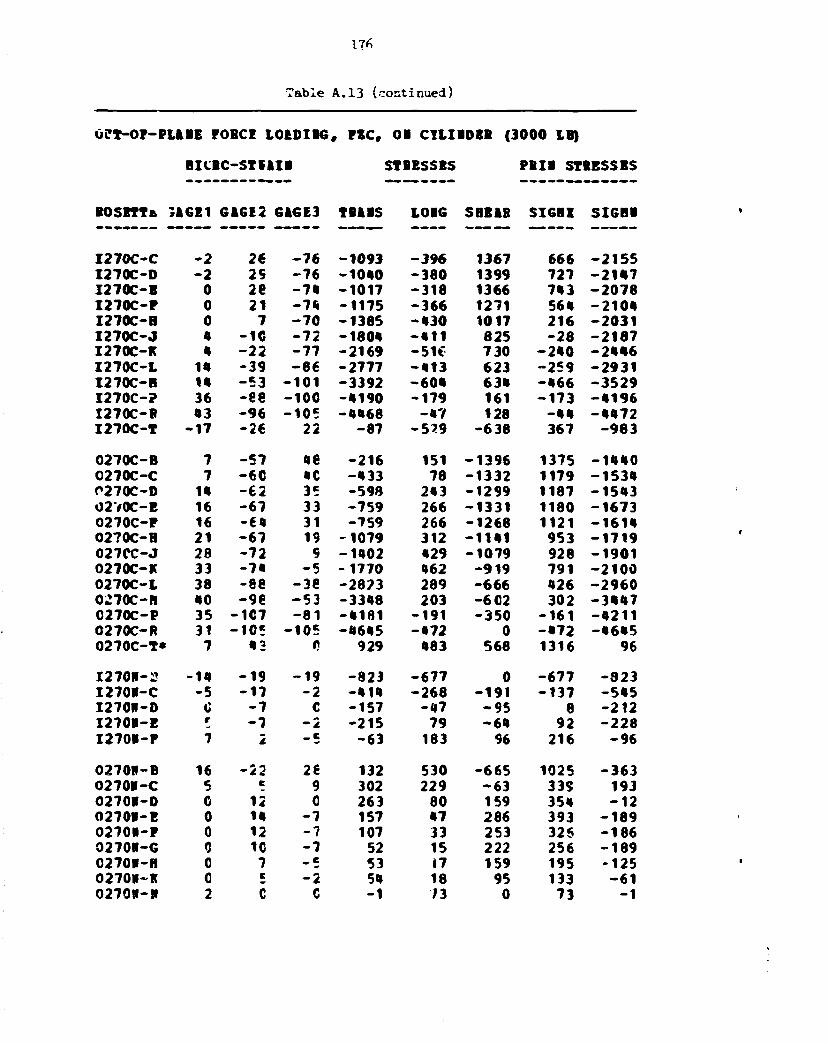
17*
Table A.13 (continued)
0?T-0P-PLiBE POBCI L0EDIB6, PIC, OB CTLIBDBB (3000 LB)
BICBC-STfllB STBBSSBS PBIB STBBSSBS
BO SETT t. 3A6E1 6 1 6 1 2 6A6E3 TBiBS L0B6 SHEIB SI6BI SI6BB
I 2 7 0 C - C - 2 26 - 7 6 - 1 0 9 3 - 3 9 6 1367 666 - 2 1 5 5 I 270C-D - 2 29 - 7 6 - 1 0 4 0 - 3 8 0 1399 727 - 2 1 4 7 I 2 7 0 C - B 0 2e - 7 4 - 1 0 1 7 - 3 1 8 1366 743 - 2 0 7 8 I 2 7 0 C - P 0 21 - 7 4 - 1 1 7 5 - 3 6 6 1271 564 - 2 1 0 4 I 2 7 0 C - H 0 7 - 7 0 - 1 3 8 5 - 4 3 0 1017 216 - 2 0 3 1 I 2 7 0 C - J 4 -1C - 7 2 - 1 8 0 4 - 4 1 1 825 - 2 8 - 2 1 8 7 I270C-R 4 - 2 2 - 7 7 - 2 1 6 9 -51C 730 - 2 4 0 - 2 4 4 6 I 2 7 0 C - L 14 - 3 9 - 8 6 - 2 7 7 7 - 4 1 3 623 - 2 5 9 - 2 9 3 1 I270C-B 14 - 5 3 - 1 0 1 - 3 3 9 2 - 6 0 4 634 - 4 6 6 - 3 5 2 9 I 2 7 0 C - ? 36 -ee - 1 0 0 - 4 1 9 0 - 1 7 9 161 - 1 7 3 - 4 1 9 6 I270C-B 43 - 9 6 - 1 0 5 - 4 4 6 8 - 4 7 128 - 4 4 - 4 4 7 2 I 2 7 0 C - T - 1 7 - 2 6 22 - 8 7 - 5 ? 9 - 6 3 8 367 - 9 8 3
O270C-B 7 - 5 7 «e - 2 1 6 151 - 1 3 9 6 1375 - 1 4 4 0 0270C-C 7 - 6 C 4C - 4 3 3 78 - 1 3 3 2 1179 - 1 5 3 4 C270C-D m - 6 2 35 - 5 9 8 243 - 1 2 9 9 1187 - 1 5 4 3 O2V0C-B 16 - 6 7 33 - 7 5 9 266 - 1 3 3 1 1180 - 1 6 7 3 O270C-P 16 - 6 4 31 - 7 5 9 266 - 1 2 6 8 1121 - 1 6 1 4 0270C-H 21 - 6 7 19 - 1 0 7 9 312 - 1 1 4 1 953 - 1 7 1 9 027CC-J 28 - 7 2 9 - 1 4 0 2 429 - 1 0 7 9 928 - 1 9 0 1 0270C-K 33 - 7 4 - 5 - 1 7 7 0 462 - 9 1 9 791 - 2 1 0 0 0 2 7 0 C - 1 38 - 8 8 -3e - 2 8 2 3 289 - 6 6 6 426 - 2 9 6 0 0270C-H 40 - 9 6 - 5 3 - 3 3 4 8 203 -6C2 302 - 3 4 4 7 0270C-P 35 -1C7 - 8 1 - 4 1 8 1 - 1 9 1 - 3 5 0 - 1 6 1 - 4 2 1 1 0270C-R 31 - 1 0 5 - 1 0 5 - 4 6 4 5 - 4 7 2 0 - 4 7 2 - 4 6 4 5 0270C-T* 7 43 t) 929 483 568 1316 96
I 2 7 0 B - 2 -14 - 1 9 - 1 9 - 8 2 3 - 6 7 7 0 - 6 7 7 - 3 2 3 I 270B-C - 5 - 1 7 - 2 - 4 1 4 - 2 6 8 - 1 9 1 - 1 3 7 - 5 4 5 I 270B-D 0 - 7 C - 1 5 7 - 4 7 - 9 5 8 - 2 1 2 I 2 7 0 B - E r - 7 - 2 - 2 1 5 79 - 6 4 92 - 2 2 8 I 2 7 0 I - P 7 2 _c - 6 3 183 96 216 - 9 6
027011-B 16 - 2 2 26 132 530 - 6 6 5 1025 - 3 6 3 0270B-C 5 e 9 302 229 - 6 3 339 193 0270M-D C 12 0 263 80 159 354 - 1 2 O270B-E 0 14 - 7 157 47 286 393 - 1 8 9 0270U-P 0 12 - 7 107 33 253 32$ - 1 8 6 0270E-6 0 10 - 7 52 15 222 256 - 1 8 9 0270B-H 0 7 _ e 53 17 159 195 - 1 2 5 0270»-K 0 c - 2 54 18 95 133 - 6 1 027011-B 2 C C - 1 73 0 73 - 1

177
Table A.13 (continued)
OOT-OP-PLftBE POBCE LCIDIiG, PZC, OB CT1IBDBB (3000 LB)
BICBO-STE1IR STBBSSBS PBIB STBBSSBS
HOSETTE GiGEI GIGE2 G1GE3 TBABS LOBG SBE1B SIGBX SIGHB
I315C-B 9 -96 -84 -3957 -905 -157 -897 -3965 I315C-C 5 - 7 4 - 6 2 -3009 -766 -159 -755 -3020 I315C-D 0 -63 -43 -2333 -695 -262 -654 -2374 I315C-P - 1 0 - 4 1 -39 -1734 -816 - 3 2 -815 -1735 I315C-H -12 - 4 1 -39 -1737 -890 - 3 1 -889 -1739 I315C-J - 1 5 - 4 3 -34 - t679 -945 -127 -923 -1701 I315C-K -15 -50 - 3 1 -1782 -977 -255 -903 -1856 I315C-L 7 -69 -24 -2058 -402 -600 -208 -2253 I315C-B - 3 -79 -10 -1943 - 6 6 1 -922 -179 -2425 I315C-P - 1 0 - 9 1 - 3 -2045 -912 -1174 -«75 -2782
0315C-B 4 -19 - 4 1 -1319 -262 284 -191 -1391 0315C-C 7 -10 - 3 1 -904 -65 286 23 -993 0315C-D 12 _ e -38 -958 61 442 226 -1123 0315C-B • 9 -38 -915 291 474 455 -1079 0315C-P 2* -10 - 3 8 -1079 381 376 472 -1170 0315C-H 2« 2 -4C -860 454 569 6(6 -1072 0115C-K 26 £ - 5 2 -1071 461 758 773 -1383 C315C-L 19 14 -69 -1220 203 1106 807 -1823 0315C-B 14 12 - 8 1 -1527 - 3 1 1233 662 -2221 0315C-P 0 7 -88 -1772 -532 1264 256 -2560
I315B-B - 7 - 69 - 8 1 -3307 -1213 160 -1201 -3319 I315B-C -38 -48 - 4 8 -2068 -1774 1 -1774 -2068 I315B-D -29 -29 -27 -1186 -1222 -32 -1167 -1241 I315B-E -17 -19 -19 -831 -758 - 1 -758 - 8 3 1 I315B-P -12 -15 -15 -627 -553 - 1 -553 -627 I315B-B - 1 C 0 - 12 -44 - 1 - 1 2 -44
0315B-E 19 - 2 1 -24 -1011 266 32 267 -1012 0315B-C 7 17 12 613 399 63 635 382 0315B-D - 6 20 23 961 104 -39 963 103 0315B-B -14 16 19 788 -177 -35 789 -178 0315B-P -14 13 12 583 -243 12 S 34 -243 0315B-G -12 10 8 408 -236 21 409 -237 0315B-B -10 7 8 335 -199 -6 335 -199 0315B-K -3 - 1 2 31 -94 -48 47 -110 0315B-B - 9 4 4 192 - 2 2 1 - 2 192 -221