thenexteditionofthisstandardisscheduledforpublicationin2020.€¦ · foreword...
TRANSCRIPT


Date of Issuance: May 5, 2017
The next edition of this Standard is scheduled for publication in 2020.
ASME issues written replies to inquiries concerning interpretations of technical aspects of this Standard. Periodically certainactions of the ASME B16 Committeemay be published as Cases. Cases and interpretations are published on the ASMEWeb siteunder the Committee Pages at http://cstools.asme.org/ as they are issued.
Errata to codes and standards may be posted on the ASME Web site under the Committee Pages to provide corrections toincorrectly published items, or to correct typographical or grammatical errors in codes and standards. Such errata shall be usedon the date posted.
The Committee Pages can be found at http://cstools.asme.org/. There is an option available to automatically receive an e-mailnotification when errata are posted to a particular code or standard. This option can be found on the appropriate CommitteePage after selecting “Errata” in the “Publication Information” section.
ASME is the registered trademark of The American Society of Mechanical Engineers.
This code or standardwas developed under procedures accredited asmeeting the criteria for American National Standards. The StandardsCommittee that approved the code or standardwas balanced to assure that individuals from competent and concerned interests have had anopportunity to participate. The proposed code or standard was made available for public review and comment that provides an opportunityfor additional public input from industry, academia, regulatory agencies, and the public-at-large.
ASME does not “approve,” “rate,” or “endorse” any item, construction, proprietary device, or activity.ASME does not take any position with respect to the validity of any patent rights asserted in connection with any items mentioned in this
document, and does not undertake to insure anyone utilizing a standard against liability for infringement of any applicable letters patent, norassumeany such liability. Usersof a codeor standardare expressly advised thatdeterminationof the validity of any suchpatent rights, and therisk of infringement of such rights, is entirely their own responsibility.
Participation by federal agency representative(s) or person(s) affiliated with industry is not to be interpreted as government or industryendorsement of this code or standard.
ASME accepts responsibility for only those interpretations of this document issued in accordance with the established ASME proceduresand policies, which precludes the issuance of interpretations by individuals.
No part of this document may be reproduced in any form,in an electronic retrieval system or otherwise,
without the prior written permission of the publisher.
The American Society of Mechanical EngineersTwo Park Avenue, New York, NY 10016-5990
Copyright © 2017 byTHE AMERICAN SOCIETY OF MECHANICAL ENGINEERS
All rights reservedPrinted in U.S.A.

CONTENTS
Foreword . . . . . . . . . . . . . . . . . . . . . . . . . . . . . . . . . . . . . . . . . . . . . . . . . . . . . . . . . . . . . . . . . . . . . . . . vi
Committee Roster . . . . . . . . . . . . . . . . . . . . . . . . . . . . . . . . . . . . . . . . . . . . . . . . . . . . . . . . . . . . . . . . . . vii
Correspondence With the B16 Committee . . . . . . . . . . . . . . . . . . . . . . . . . . . . . . . . . . . . . . . . . . . . . . . . . viii
Summary of Changes . . . . . . . . . . . . . . . . . . . . . . . . . . . . . . . . . . . . . . . . . . . . . . . . . . . . . . . . . . . . . . . . x
List of Changes in Record Number Order . . . . . . . . . . . . . . . . . . . . . . . . . . . . . . . . . . . . . . . . . . . . . . . . . xi
1 Scope . . . . . . . . . . . . . . . . . . . . . . . . . . . . . . . . . . . . . . . . . . . . . . . . . . . . . . . . . . . . . . . . . . 12 Pressure–Temperature Ratings . . . . . . . . . . . . . . . . . . . . . . . . . . . . . . . . . . . . . . . . . . . . . . 23 Component Size: Nominal Pipe Size . . . . . . . . . . . . . . . . . . . . . . . . . . . . . . . . . . . . . . . . . . . 34 Marking . . . . . . . . . . . . . . . . . . . . . . . . . . . . . . . . . . . . . . . . . . . . . . . . . . . . . . . . . . . . . . . . 35 Materials . . . . . . . . . . . . . . . . . . . . . . . . . . . . . . . . . . . . . . . . . . . . . . . . . . . . . . . . . . . . . . . 46 Dimensions . . . . . . . . . . . . . . . . . . . . . . . . . . . . . . . . . . . . . . . . . . . . . . . . . . . . . . . . . . . . . 57 Tolerances . . . . . . . . . . . . . . . . . . . . . . . . . . . . . . . . . . . . . . . . . . . . . . . . . . . . . . . . . . . . . . 68 Pressure Testing . . . . . . . . . . . . . . . . . . . . . . . . . . . . . . . . . . . . . . . . . . . . . . . . . . . . . . . . . 7
Mandatory AppendicesI Pressure–Temperature Ratings and Dimensional Data for Classes 75, 150, 300, 400, 600, and 900
Flanges in U.S. Customary Units . . . . . . . . . . . . . . . . . . . . . . . . . . . . . . . . . . . . . . . . . . . . . 52II References . . . . . . . . . . . . . . . . . . . . . . . . . . . . . . . . . . . . . . . . . . . . . . . . . . . . . . . . . . . . . . 95
Nonmandatory AppendicesA Methods Used for Establishing Pressure–Temperature Ratings . . . . . . . . . . . . . . . . . . . . . . . . . 97B Gaskets (Other Than Ring-Joint) . . . . . . . . . . . . . . . . . . . . . . . . . . . . . . . . . . . . . . . . . . . . . . . 101C Quality System Program . . . . . . . . . . . . . . . . . . . . . . . . . . . . . . . . . . . . . . . . . . . . . . . . . . . . . 103
Figures1 Welding Ends (Welding Neck Flanges, No Backing Rings) . . . . . . . . . . . . . . . . . . . . . . . . . . . . . 72 Welding Ends (Welding Neck Flanges With Backing Rings) . . . . . . . . . . . . . . . . . . . . . . . . . . . . 83 Welding Ends (Welding Neck Flanges) . . . . . . . . . . . . . . . . . . . . . . . . . . . . . . . . . . . . . . . . . . 9I-1 Welding Ends (Welding Neck Flanges, No Backing Rings) . . . . . . . . . . . . . . . . . . . . . . . . . . . . . 53I-2 Welding Ends (Welding Neck Flanges With Backing Rings) . . . . . . . . . . . . . . . . . . . . . . . . . . . . 54I-3 Welding Ends (Welding Neck Flanges) . . . . . . . . . . . . . . . . . . . . . . . . . . . . . . . . . . . . . . . . . . 55
Tables1 List of Material Specifications . . . . . . . . . . . . . . . . . . . . . . . . . . . . . . . . . . . . . . . . . . . . . . . . . 102 List of Bolting Specifications (Applicable ASTM Specifications) . . . . . . . . . . . . . . . . . . . . . . . . . 123 Pressure–Temperature Ratings for Group 1.1 Materials . . . . . . . . . . . . . . . . . . . . . . . . . . . . . . 134 Pressure–Temperature Ratings for Group 1.2 Materials . . . . . . . . . . . . . . . . . . . . . . . . . . . . . . 145 Pressure–Temperature Ratings for Group 1.3 Materials . . . . . . . . . . . . . . . . . . . . . . . . . . . . . . 15
iii

6 Pressure–Temperature Ratings for Group 1.4 Materials . . . . . . . . . . . . . . . . . . . . . . . . . . . . . . 167 Pressure–Temperature Ratings for Group 1.5 Materials . . . . . . . . . . . . . . . . . . . . . . . . . . . . . . 178 Pressure–Temperature Ratings for Group 1.7 Materials . . . . . . . . . . . . . . . . . . . . . . . . . . . . . . 189 Pressure–Temperature Ratings for Group 1.9 Materials . . . . . . . . . . . . . . . . . . . . . . . . . . . . . . 1910 Pressure–Temperature Ratings for Group 1.10 Materials . . . . . . . . . . . . . . . . . . . . . . . . . . . . . 2011 Pressure–Temperature Ratings for Group 1.11 Materials . . . . . . . . . . . . . . . . . . . . . . . . . . . . . 2112 Pressure–Temperature Ratings for Group 1.13 Materials . . . . . . . . . . . . . . . . . . . . . . . . . . . . . 2213 Pressure–Temperature Ratings for Group 1.14 Materials . . . . . . . . . . . . . . . . . . . . . . . . . . . . . 2314 Pressure–Temperature Ratings for Group 1.15 Materials . . . . . . . . . . . . . . . . . . . . . . . . . . . . . 2415 Pressure–Temperature Ratings for Group 1.17 Materials . . . . . . . . . . . . . . . . . . . . . . . . . . . . . 2516 Pressure–Temperature Ratings for Group 1.18 Materials . . . . . . . . . . . . . . . . . . . . . . . . . . . . . 2617 Pressure–Temperature Ratings for Group 2.1 Materials . . . . . . . . . . . . . . . . . . . . . . . . . . . . . . 2718 Pressure–Temperature Ratings for Group 2.2 Materials . . . . . . . . . . . . . . . . . . . . . . . . . . . . . . 2819 Pressure–Temperature Ratings for Group 2.3 Materials . . . . . . . . . . . . . . . . . . . . . . . . . . . . . . 2920 Pressure–Temperature Ratings for Group 2.4 Materials . . . . . . . . . . . . . . . . . . . . . . . . . . . . . . 3021 Pressure–Temperature Ratings for Group 2.5 Materials . . . . . . . . . . . . . . . . . . . . . . . . . . . . . . 3122 Pressure–Temperature Ratings for Group 2.6 Materials . . . . . . . . . . . . . . . . . . . . . . . . . . . . . . 3223 Pressure–Temperature Ratings for Group 2.7 Materials . . . . . . . . . . . . . . . . . . . . . . . . . . . . . . 3324 Pressure–Temperature Ratings for Group 2.8 Materials . . . . . . . . . . . . . . . . . . . . . . . . . . . . . . 3425 Pressure–Temperature Ratings for Group 2.9 Materials . . . . . . . . . . . . . . . . . . . . . . . . . . . . . . 3526 Pressure–Temperature Ratings for Group 2.10 Materials . . . . . . . . . . . . . . . . . . . . . . . . . . . . . 3627 Pressure–Temperature Ratings for Group 2.11 Materials . . . . . . . . . . . . . . . . . . . . . . . . . . . . . 3728 Pressure–Temperature Ratings for Group 2.12 Materials . . . . . . . . . . . . . . . . . . . . . . . . . . . . . 3829 Dimensions of Ring-Joint Facings . . . . . . . . . . . . . . . . . . . . . . . . . . . . . . . . . . . . . . . . . . . . . . 3930 Permissible Imperfections in Flange Facing Finish . . . . . . . . . . . . . . . . . . . . . . . . . . . . . . . . . . 3931 Dimensions of Class 150 Series A Flanges . . . . . . . . . . . . . . . . . . . . . . . . . . . . . . . . . . . . . . . . 4032 Dimensions of Class 300 Series A Flanges . . . . . . . . . . . . . . . . . . . . . . . . . . . . . . . . . . . . . . . . 4133 Dimensions of Class 400 Series A Flanges . . . . . . . . . . . . . . . . . . . . . . . . . . . . . . . . . . . . . . . . 4234 Dimensions of Class 600 Series A Flanges . . . . . . . . . . . . . . . . . . . . . . . . . . . . . . . . . . . . . . . . 4335 Dimensions of Class 900 Series A Flanges . . . . . . . . . . . . . . . . . . . . . . . . . . . . . . . . . . . . . . . . 4436 Dimensions of Class 75 Series B Flanges . . . . . . . . . . . . . . . . . . . . . . . . . . . . . . . . . . . . . . . . . 4537 Dimensions of Class 150 Series B Flanges . . . . . . . . . . . . . . . . . . . . . . . . . . . . . . . . . . . . . . . . 4638 Dimensions of Class 300 Series B Flanges . . . . . . . . . . . . . . . . . . . . . . . . . . . . . . . . . . . . . . . . 4739 Dimensions of Class 400 Series B Flanges . . . . . . . . . . . . . . . . . . . . . . . . . . . . . . . . . . . . . . . . 4840 Dimensions of Class 600 Series B Flanges . . . . . . . . . . . . . . . . . . . . . . . . . . . . . . . . . . . . . . . . 4941 Dimensions of Class 900 Series B Flanges . . . . . . . . . . . . . . . . . . . . . . . . . . . . . . . . . . . . . . . . 5042 Flange Bolting Dimensional Recommendations . . . . . . . . . . . . . . . . . . . . . . . . . . . . . . . . . . . . . 51I-1 Pressure–Temperature Ratings for Group 1.1 Materials . . . . . . . . . . . . . . . . . . . . . . . . . . . . . . 56I-2 Pressure–Temperature Ratings for Group 1.2 Materials . . . . . . . . . . . . . . . . . . . . . . . . . . . . . . 57I-3 Pressure–Temperature Ratings for Group 1.3 Materials . . . . . . . . . . . . . . . . . . . . . . . . . . . . . . 58I-4 Pressure–Temperature Ratings for Group 1.4 Materials . . . . . . . . . . . . . . . . . . . . . . . . . . . . . . 59I-5 Pressure–Temperature Ratings for Group 1.5 Materials . . . . . . . . . . . . . . . . . . . . . . . . . . . . . . 60I-6 Pressure–Temperature Ratings for Group 1.7 Materials . . . . . . . . . . . . . . . . . . . . . . . . . . . . . . 61I-7 Pressure–Temperature Ratings for Group 1.9 Materials . . . . . . . . . . . . . . . . . . . . . . . . . . . . . . 62I-8 Pressure–Temperature Ratings for Group 1.10 Materials . . . . . . . . . . . . . . . . . . . . . . . . . . . . . 63
iv

I-9 Pressure–Temperature Ratings for Group 1.11 Materials . . . . . . . . . . . . . . . . . . . . . . . . . . . . . 64I-10 Pressure–Temperature Ratings for Group 1.13 Materials . . . . . . . . . . . . . . . . . . . . . . . . . . . . . 65I-11 Pressure–Temperature Ratings for Group 1.14 Materials . . . . . . . . . . . . . . . . . . . . . . . . . . . . . 66I-12 Pressure–Temperature Ratings for Group 1.15 Materials . . . . . . . . . . . . . . . . . . . . . . . . . . . . . 67I-13 Pressure–Temperature Ratings for Group 1.17 Materials . . . . . . . . . . . . . . . . . . . . . . . . . . . . . 68I-14 Pressure–Temperature Ratings for Group 1.18 Materials . . . . . . . . . . . . . . . . . . . . . . . . . . . . . 69I-15 Pressure–Temperature Ratings for Group 2.1 Materials . . . . . . . . . . . . . . . . . . . . . . . . . . . . . . 70I-16 Pressure–Temperature Ratings for Group 2.2 Materials . . . . . . . . . . . . . . . . . . . . . . . . . . . . . . 71I-17 Pressure–Temperature Ratings for Group 2.3 Materials . . . . . . . . . . . . . . . . . . . . . . . . . . . . . . 72I-18 Pressure–Temperature Ratings for Group 2.4 Materials . . . . . . . . . . . . . . . . . . . . . . . . . . . . . . 73I-19 Pressure–Temperature Ratings for Group 2.5 Materials . . . . . . . . . . . . . . . . . . . . . . . . . . . . . . 74I-20 Pressure–Temperature Ratings for Group 2.6 Materials . . . . . . . . . . . . . . . . . . . . . . . . . . . . . . 75I-21 Pressure–Temperature Ratings for Group 2.7 Materials . . . . . . . . . . . . . . . . . . . . . . . . . . . . . . 76I-22 Pressure–Temperature Ratings for Group 2.8 Materials . . . . . . . . . . . . . . . . . . . . . . . . . . . . . . 77I-23 Pressure–Temperature Ratings for Group 2.9 Materials . . . . . . . . . . . . . . . . . . . . . . . . . . . . . . 78I-24 Pressure–Temperature Ratings for Group 2.10 Materials . . . . . . . . . . . . . . . . . . . . . . . . . . . . . 79I-25 Pressure–Temperature Ratings for Group 2.11 Materials . . . . . . . . . . . . . . . . . . . . . . . . . . . . . 80I-26 Pressure–Temperature Ratings for Group 2.12 Materials . . . . . . . . . . . . . . . . . . . . . . . . . . . . . 81I-27 Dimensions of Ring-Joint Facings . . . . . . . . . . . . . . . . . . . . . . . . . . . . . . . . . . . . . . . . . . . . . . 82I-28 Permissible Imperfections in Flange Facing Finish . . . . . . . . . . . . . . . . . . . . . . . . . . . . . . . . . . 83I-29 Dimensions of Class 150 Series A Flanges . . . . . . . . . . . . . . . . . . . . . . . . . . . . . . . . . . . . . . . . 84I-30 Dimensions of Class 300 Series A Flanges . . . . . . . . . . . . . . . . . . . . . . . . . . . . . . . . . . . . . . . . 85I-31 Dimensions of Class 400 Series A Flanges . . . . . . . . . . . . . . . . . . . . . . . . . . . . . . . . . . . . . . . . 86I-32 Dimensions of Class 600 Series A Flanges . . . . . . . . . . . . . . . . . . . . . . . . . . . . . . . . . . . . . . . . 87I-33 Dimensions of Class 900 Series A Flanges . . . . . . . . . . . . . . . . . . . . . . . . . . . . . . . . . . . . . . . . 88I-34 Dimensions of Class 75 Series B Flanges . . . . . . . . . . . . . . . . . . . . . . . . . . . . . . . . . . . . . . . . . 89I-35 Dimensions of Class 150 Series B Flanges . . . . . . . . . . . . . . . . . . . . . . . . . . . . . . . . . . . . . . . . 90I-36 Dimensions of Class 300 Series B Flanges . . . . . . . . . . . . . . . . . . . . . . . . . . . . . . . . . . . . . . . . 91I-37 Dimensions of Class 400 Series B Flanges . . . . . . . . . . . . . . . . . . . . . . . . . . . . . . . . . . . . . . . . 92I-38 Dimensions of Class 600 Series B Flanges . . . . . . . . . . . . . . . . . . . . . . . . . . . . . . . . . . . . . . . . 93I-39 Dimensions of Class 900 Series B Flanges . . . . . . . . . . . . . . . . . . . . . . . . . . . . . . . . . . . . . . . . 94A-1 Rating Ceiling Values in bar . . . . . . . . . . . . . . . . . . . . . . . . . . . . . . . . . . . . . . . . . . . . . . . . . . 99A-2 Rating Ceiling Values in psig . . . . . . . . . . . . . . . . . . . . . . . . . . . . . . . . . . . . . . . . . . . . . . . . . . 100B-1 Gasket Groups and Typical Materials . . . . . . . . . . . . . . . . . . . . . . . . . . . . . . . . . . . . . . . . . . . . 102
v

FOREWORD
In November 1980, a task forcewas appointedwithin Subcommittee C of the AmericanNational Standards (ANSI) B16Committee todevelop a standard for pipe flanges in sizesNPS26 throughNPS48. Every attemptwasmade to standardizethose dimensions that existed within the industry for the materials covered by ANSI B16.5.Promptedby suggestions fromcommitteemembers, the task forcewas authorized to increase the size range toNPS60.
The first draftwas developed inDecember 1982 to include Class 75 through Class 1500 for the size rangeNPS26 throughNPS 60. Flange dimensions were based on the Manufacturers Standardization Society, Standard Practice (MSS SP) 44flanges, except for Class 75 flanges that are ANSI/API 605 flanges.At the request of the American Petroleum Institute (API), flange dimensions, in accordancewith the API Standard 605,
were included in the subsequent drafts. Class 1500 flangesweredeleteddue to a lackof interest inusing large-size flangesin that pressure–temperature rating.The API 605 flanges for Classes 150 and 300 and for sizes NPS 36 and smaller for classes higher than Class 300 are not
compatible with the MSS SP-44 flanges. Thus, the MSS SP-44 flanges are designated as Series A flanges, and the API 605flanges are designated as Series B flanges in this Standard.Materials covered in this Standard are as in ANSI B16.5, exceptnickel base alloys are excluded. Pressure–temperature ratings are in accordance with ANSI B16.5.In 1982, American National Standards Committee B16 was reorganized as the American Society of Mechanical
Engineers (ASME) B16 Committee operating under procedures accredited by ANSI. Following approval by theStandards Committee and ASME, approval as an American National Standard was given by ANSI on June 12, 1990.The 1996Edition allowed flangesmarkedwithmore than onematerial grade or specification, revised flange face finish
requirements, revised pressure–temperature ratings for severalmaterial groups, addedpermissible flange facing imper-fections, added blind flanges for Series B flanges, and included several other revisions. Following approval by theStandards Committee and ASME, Boiler and Pressure Vessel Committee, ANSI approved the previous edition as anAmerican National Standard on October 3, 1996, with the new designation ASME B16.47-1996.In2006, several revisionsweremade, includinguse ofmetric units as primaryunits,withU.S. Customaryunits in either
parenthetical or separate forms.MandatoryAppendix Iwas provided after themain text for convenience to cover ratingsand dimensions in U.S. Customary units. Inch dimension bolt holes were retained for flanges manufactured to metricdimensions to avoid fit-up problems. Development ofmetric dimensionswas done to reflect the intendedprecision of thedimension rather than by numerical conversion. For some materials, pressure–temperature ratings were revised toreflect revisions to material strength properties (tensile and yield) listed in the ASME Boiler and Pressure Vessel Code,Section II. Somematerials were assigned to different rating tables in order tominimize changes to ratings for commonlyused materials. Following the approvals of the Standards Committee and ASME, approval for the revised edition wasgranted by the American National Standards Institute on November 6, 2006.In the 2011 edition, the References section was revised to cover the requirements of material specification editions
other than those listed inMandatory Appendix III. Following approval by the Standards Committee and the ASME Boardon PTCS, the 2011 revision was approved as an American National Standard by ANSI on August 17, 2011 with the newdesignation, ASME B16.47-2011.In the 2017 edition, pressure–temperature ratings for Group 1.18 materials were revised at 650°C (1,200°F). A refer-
ence was made to MSS SP-44 for some classes of flanges made with materials having a high yield strength. A forgingrequirement was made explicit, and references were updated.Followingapprovalby theASMEB16StandardsCommittee, this editionwasapprovedbyANSI asanAmericanNational
Standard on March 6, 2017, with the new designation ASME B16.47-2017.
vi

ASME B16 COMMITTEEStandardization of Valves, Flanges, Fittings, and Gaskets
(The following is the roster of the Committee at the time of approval of this Standard.)
STANDARDS COMMITTEE OFFICERSR. M. Bojarczuk, ChairC. E. Davila, Vice ChairC. Ramcharran, Secretary
STANDARDS COMMITTEE PERSONNEL
A. Appleton, Alloy Stainless Products Co., Inc.J. E. Barker, Dezurik Water ControlsR. W. Barnes, Anric Enterprises, Inc.K. Barron, Ward ManufacturingD. C. Bayreuther, Metso Automation, Flow Control DivisionW. B. Bedesem, ConsultantR. M. Bojarczuk, ExxonMobil Research & Engineering Co.A. M. Cheta, Qatar Shell GTLM. A. Clark, NIBCO, Inc.P. V. Craig, Contributing Member, Jomar GroupG. A. Cuccio, Capital Manufacturing Co.J. D’Avanzo, Fluoroseal ValvesC. E. Davila, Crane EnergyB. F. Fabian, Contributing Member, Pennsylvania Machine WorksF. Feng, Delegate, China Productivity Center for MachineryD. R. Frikken, Becht Engineering Co.
R. B. Hai, RBH AssociatesG. A. Jolly, ConsultantM. Katcher, Haynes InternationalA. G. Kireta, Jr., Contributing Member, Copper DevelopmentAssociation, Inc.
T. A. McMahon, Emerson Process ManagementP. Milankov, Alternate, ConsultantM. L. Nayyar, NICEW. H. Patrick, The Dow Chemical Co.D. Rahoi, ConsultantC. Ramcharran, The American Society of Mechanical EngineersD. F. Reid, Contributing Member, VSP TechnologiesR. A. Schmidt, CanadoilJ. P. Tucker, FlowserveF. R. Volgstadt, Volgstadt & Associates, Inc.
SUBCOMMITTEE C — STEEL FLANGES AND FLANGED FITTINGS
A. M. Cheta, Chair, Qatar Shell GTLR. Lucas, Secretary, The American Society of Mechanical EngineersA. Appleton, Alloy Stainless Products Co., Inc.W. B. Bedesem, ConsultantC. E. Davila, Crane EnergyB. Dennis, Kerkau ManufacturingJ. P. Ellenberger, ConsultantD. R. Frikken, Becht Engineering Co.E. Gulgun, International Standard Valve, Inc.G. B. Hailegiorgis, Ameriforge Group, Inc.J. R. Holstrom, Val-Matic Valve & Manufacturing Corp.
M. Katcher, Haynes InternationalM. L. Nayyar, NICEW. H. Patrick, The Dow Chemical Co.D. W. Rahoi, ConsultantT. V. Ramakrishnan, Forged Components, Inc.R. A. Schmidt, CanadoilD. E. Tezzo, Pentair Valves & ControlsJ. P. Tucker, FlowserveG. T. Walden, WolseleyM. M. Zaidi, Jacobs Engineering
vii
Производство фланцев большого диаметра по ASME B 16.47https://tekkos.ru/katalog/detali-truboprovodov/flancy-po-asme-ansi-din-en.html

CORRESPONDENCE WITH THE B16 COMMITTEE
General. ASME Standards are developed and maintained with the intent to represent the consensus of concernedinterests. As such, users of this Standard may interact with the Committee by requesting interpretations, proposingrevisions or a case, and attending Committee meetings. Correspondence should be addressed to:
Secretary, B16 Standards CommitteeThe American Society of Mechanical EngineersTwo Park AvenueNew York, NY 10016-5990http://go.asme.org/Inquiry
Proposing Revisions. Revisions are made periodically to the Standard to incorporate changes that appear necessaryor desirable, as demonstrated by the experience gained from the application of the Standard. Approved revisions will bepublished periodically.The Committee welcomes proposals for revisions to this Standard. Such proposals should be as specific as possible,
citing the paragraph number(s), the proposed wording, and a detailed description of the reasons for the proposal,including any pertinent documentation.
Proposing a Case. Casesmay be issued to provide alternative rules when justified, to permit early implementation ofan approved revision when the need is urgent, or to provide rules not covered by existing provisions. Cases are effectiveimmediately upon ASME approval and shall be posted on the ASME Committee Web page.Requests for Cases shall provide a Statement of Need and Background Information. The request should identify the
Standard and the paragraph, figure, or table number(s), and be written as a Question and Reply in the same format asexisting Cases. Requests for Cases should also indicate the applicable edition(s) of the Standard to which the proposedCase applies.
Interpretations. Upon request, the B16 Standards Committeewill render an interpretation of any requirement of theStandard. Interpretations canonlybe rendered in response to awritten request sent to theSecretaryof theB16StandardsCommittee.Requests for interpretation should preferably be submitted through the online Interpretation Submittal Form. The
form is accessible at http://go.asme.org/InterpretationRequest. Upon submittal of the form, the Inquirer will receive anautomatic e-mail confirming receipt.If the Inquirer is unable to use the online form, he/she may e-mail the request to the Secretary of the B16 Standards
Committee at [email protected], or mail it to the above address. The request for an interpretation should be clearand unambiguous. It is further recommended that the Inquirer submit his/her request in the following format:
Subject: Cite the applicable paragraph number(s) and the topic of the inquiry in one or two words.Edition: Cite the applicable edition of the Standard for which the interpretation is being requested.Question: Phrase the question as a request for an interpretation of a specific requirement suitable for
general understanding and use, not as a request for an approval of a proprietary design orsituation. Please provide a condensed and precise question, composed in such away that a“yes” or “no” reply is acceptable.
Proposed Reply(ies): Provide a proposed reply(ies) in the form of “Yes” or “No,” with explanation as needed. Ifentering replies to more than one question, please number the questions and replies.
Background Information: Provide the Committee with any background information that will assist the Committee inunderstanding the inquiry. The Inquirer may also include any plans or drawings that arenecessary to explain the question; however, they should not contain proprietary names orinformation.
viii

Requests that arenot in the format describedabovemaybe rewritten in the appropriate formatby theCommitteepriorto being answered, which may inadvertently change the intent of the original request.ASMEprocedures provide for reconsideration of any interpretationwhen or if additional information thatmight affect
an interpretation is available. Further, persons aggrieved by an interpretation may appeal to the cognizant ASMECommittee or Subcommittee. ASME does not “approve,” “certify,” “rate,” or “endorse” any item, construction, proprietarydevice, or activity.
Attending Committee Meetings. The B16 Standards Committee regularly holds meetings and/or telephone confer-ences that are open to the public. Personswishing to attend anymeeting and/or telephone conference should contact theSecretary of the B16 Standards Committee.
ix

ASME B16.47-2017SUMMARY OF CHANGES
Following approval by the ASME B16 Committee and ASME, and after public review, ASME B16.47-2017 was approved by theAmerican National Standards Institute on March 6, 2017.
ASME B16.47-2017 includes the following changes identified by a margin note, (17).
Page Location Change (Record Number)2 1.11 Added (13-592)4 5.1 New subpara. (b) added, and subsequent
subparas. redesignated (11-544)26 Table 16 For 650°C, values in third, fifth, and sixth
columns revised (15-2359)51 Table 42 (1) For Stud bolts, ASME reference revised
(14-2174)(2) Note (1) deleted (14-2174)
69 Table I-14 For 1,200°F, values in third, fifth, and sixthcolumns revised (15-2359)
95 Mandatory Appendix II References updated103 Nonmandatory Appendix C Former Mandatory Appendix II
redesignated as NonmandatoryAppendix C
x

LIST OF CHANGES IN RECORD NUMBER ORDER
Record Number Change11-544 Revised para. 5.1 to explicitly require forgings to be made near the shape of the finished
flange.13-592 Added new para. 1.11 to offer guidance for flange material used with high yield strength
pipe (40,000 psi) not covered in Table 1.14-2174 Updated references for Stud bolts in Table 42.15-2359 Updated Table 16, Working Pressure for Classes 300, 600, and 900 at 650°C. Updated
Table I-14, Working Pressure for Classes 300, 600, and 900 at 1,200°F.
xi
Производство фланцев большого диаметра по ASME B 16.47https://tekkos.ru/katalog/detali-truboprovodov/flancy-po-asme-ansi-din-en.html

INTENTIONALLY LEFT BLANK
xii

LARGE DIAMETER STEEL FLANGESNPS 26 Through NPS 60Metric/Inch Standard
1 SCOPE
1.1 General
This Standard covers pressure–temperature ratings,materials, dimensions, tolerances, marking, and testingfor pipe flanges in sizes NPS 26 through NPS 60.Included are flanges with rating class designations 75,150, 300, 400, 600, and 900 with requirements giveninbothSI (Metric) andU.S. Customaryunits,withdiameterof bolts and flange bolt holes expressed in inch units.This Standard is limited to(a) flanges made from cast or forged materials(b) blind flangesmade from cast, forged, or platemate-
rials (see Tables 1 and 2)Also included in this Standard are requirements and
recommendations regarding flange bolting, flangegaskets, and flange joints.
1.2 Flange Series
This Standard provides two series of flange dimensions.Series A specifies flange dimensions for general useflanges. Series B specifies flange dimensions forcompact flanges that, in most cases, have smaller boltcircle diameters than Series A flanges. These twoseries of flanges are, in general, not interchangeable.The user should recognize that some flanged valves,equipment bolted between flanges, and flanged equip-ment may be compatible with only one series of theseflanges.
1.3 References
Codes, standards, and specifications, containing provi-sions to the extent referenced herein, constitute require-ments of this Standard. These references are listed inMandatory Appendix II.
1.4 Time of Purchase,Manufacture, or Installation
The pressure–temperature ratings in this Standard areapplicable upon its publication to all flanges within itsscope that otherwise meet its requirement. For unusedflanges maintained in inventory, the manufacturer ofthe flange may certify conformance to this edition,provided that it can be demonstrated that all require-ments of this edition have been met. Where such compo-nents were installed in accordance with the pressure–temperature ratings of an earlier edition of this
Standard, those ratings are applicable, except as maybe governed by the applicable code or regulation.
1.5 User Accountability
This Standard cites responsibilities that are to beassumed by the flange user in the areas of, for example(a) application(b) installation(c) system pressure testing(d) operation(e) material selection
1.6 Quality Systems
Requirements relating to the product manufacturer’sq u a l i t y s y s t em p r o g r am a r e d e s c r i b e d i nNonmandatory Appendix C.
1.7 Relevant Units
This Standard states values in both SI (Metric) and U.S.Customary units. As an exception, diameter of bolts andflange bolt holes are expressed in inch units only. Thesesystemsof units are tobe regardedseparately as standard.Within the text, the U.S. Customary units are shown inparentheses or in separate tables that appear inMandatory Appendix I. The values stated in eachsystem are not exact equivalents; therefore, it is requiredthat each system of units be used independently of theother. Except for diameter of bolts and flange boltholes, combining values from the two systems constitutesnonconformance with the Standard.
1.8 Selection of Materials
Criteria for selection of materials suitable for particularfluid service are not within the scope of this Standard.
1.9 Convention
For determining conformance with this Standard, theconvention for fixing significant digits where limits(maximum and minimum values) are specified shall beas defined in ASTM Practice E29. This requires that anobserved or calculated value be rounded off to thenearest unit in the last right-handdigit used for expressingthe limit. Decimal values and tolerances do not imply aparticular method of measurement.
ASME B16.47-2017
1

1.10 Denotation1.10.1 Pressure RatingDesignation. Class, followed by
a dimensionless number, is the designation for pressure–temperature ratings (i.e., Class 75, Class 150, Class 300,Class 400, Class 600, Class 900).
1.10.2 Size. NPS, followed by a dimensionless number,is the designation for nominal flange size. NPS is related tothe reference nominal diameter, DN, used in internationaland other standards. For the sizes covered in thisStandard, the relationship is DN = 25 × NPS.
ð17Þ 1.11 Similar Flanges
MSS SP-44 covers similar Class 150, 300, 400, 600, and900 flanges for use with high strength pipe made frommaterials having yield strength greater than 276 MPa(40,000 psi) resulting in large inside pipe diameterand thinner pipe wall. See para. 2.7.
2 PRESSURE–TEMPERATURE RATINGS
2.1 General
Pressure–temperature ratings are maximum allowableworking gage pressures, in bar units, at the temperaturesin degrees Celsius shown in Tables 3 through 28 for theapplicable material and class designation. Tables I-1through I-26 of Mandatory Appendix I lists pressure–temperature ratings using pounds per square inch(psi) units for pressure at the temperature in degreesFahrenheit. For intermediate temperatures, linear inter-polation is permitted. Interpolation between class desig-nations is not permitted.
2.2 Flanged Joints
A flanged joint is composed of separate and indepen-dent, although interrelated, components: the flanges, thegasket, and the bolting, which are assembled by anotherinfluence, the assembler. Proper controls must be exer-cised in the selection and application for all of theseelements to attain a joint that has acceptable leak tight-ness. Assembly and tightening techniques, such ascontrolled bolt tightening, are described in ASME PCC-1.
2.3 Ratings of Flanged Joints2.3.1 Basis. Pressure–temperature ratings apply to
flanged joints that conform to the limitations onbolting in para. 5.3 and on gaskets in para. 5.4, andthat are made up in accordance with good practice foralignment and assembly (see para. 2.2). Use of theseratings for flanged joints not conforming to these limita-tions is the responsibility of the user.
2.3.2 Mixed Flanged Joints. If the two flanges in aflanged joint do not have the same pressure–temperaturerating, the rating of the joint at any temperature is thelower of the two flange ratings at that temperature.
2.4 Rating Temperature
The temperature shown for a corresponding pressurerating is the temperature of the pressure containing shellof the component. In general, this temperature is the sameas that of the contained fluid. Use of a pressure ratingcorresponding to a temperature other than that of thecontained fluid is the responsibility of the user, subjectto the requirements of applicable codes and regulations.For any temperature below −29°C (−20°F) the rating shallbenogreater than the rating shown for −29°C (−20°F). Seealso para. 2.5.3.
2.5 Temperature Considerations2.5.1 General. Use of flanges at either high or low
temperatures shall take into consideration the risk ofjoint leakage due to forces and moments developed inthe connected piping or equipment. Provisions inparas. 2.5.2 and 2.5.3 are included as advisory with theaim of lessening these risks.
2.5.2 High Temperature. Application at temperaturesin the creep range will result in decreasing bolt loads asrelaxation of flanges, bolts, and gaskets takes place.Flanged joints subjected to thermal gradients may like-wise be subject to decreasing bolt loads. Decreasedbolt loads diminish the capacity of the flanged joint tosustain loads effectivelywithout leakage. At temperaturesabove 200°C (400°F) for Classes 75 and 150, and above400°C (750°F) for other class designations, flanged jointsmay develop leakage problems unless care is taken toavoid imposing severe external loads and/or severethermal gradients.
2.5.3 LowTemperature. Someof thematerials listed inTables 1 and2, notably some carbon steels,mayundergo adecrease in ductility when used at low temperatures tosuch an extent as to be unable to safely resist shockloading, sudden changes of stress, or high stress concen-tration. Some codes or regulations may require impacttesting for applications even where temperatures arehigher than −29°C (−20°F). When such requirementsapply, it is the responsibility of the user to ensurethese requirements are communicated to the manufac-turer prior to the time of purchase.
2.6 System Pressure Testing
Flanged joints may be subjected to system pressuretests at a pressure of 1.5 times the 38°C (100°F) ratingrounded off to the next higher 1 bar (25 psi) increment.Testing at any higher pressure is the responsibility of the
ASME B16.47-2017
2

user, taking into account the requirements of the applic-able code or regulation.
2.7 Welding Neck Flanges2.7.1 Maximum Bore Size. Ratings for welding neck
flanges covered by this Standard are based upon theirhubs at the welding end having a thickness at leastequal to that calculated for pipe having a 276 MPa(40,000 psi) specified minimum yield strength. Toensure adequate flange hub thickness for flange sizesNPS 26 and larger, the bore of a welding neck flange,dimension B as shown in Figures 1 and 2, shall notexceed Bmax determined as follows:
Class Bmax75 0.9971A150 0.9942A300 0.9850A400 0.9800A600 0.9700A900 0.9550A
A = tabulated hub diameter, beginning of chamferas listed in the dimensional tables
Bmax = maximum permissible diameter for the bore ofa welding neck flang
The resultant units for diameter Bmax are the same asthose entered for diameter A.
2.7.2 ComponentsofUnequalStrength.The tabulatedratings for welding neck flanges are independent ofcomponentsofunequal strengthorunequalwall thicknessto which they may be attached. For all attachments, thepressure rating of the flange shall not be exceeded.
2.7.3 Attachment Welds. Attachment welds should bemade in accordance with the applicable code or regula-tion. See para. 6.4 and Figure 3 for weld end dimensionalrequirements.
2.8 Multiple Material Grades
Materials for flanges may meet the requirements ofmore than one specification or the requirements ofmore than one grade of a specification listed in Table1. In either case, the pressure–temperature ratings foranyof these specificationsorgradesmaybeusedprovidedthat thematerial ismarked in accordancewith para. 4.2.8.
3 COMPONENT SIZE: NOMINAL PIPE SIZE
As applied in this Standard, the use of the phrase“nominal pipe size,” or the designation NPS followedby a dimensionless number, is for the purpose of pipeor flange end connection size identification. Thenumber is not the same as the flange inside diameter.
4 MARKING
4.1 General
Except as modified herein, flanges shall be marked asrequired in MSS SP-25, except as noted in para. 4.2.
4.2 Identification Markings4.2.1 Name. The manufacturer’s name or trademark
shall be applied.
4.2.2 Materials. Materials shall be identified in thefollowing ways:(a) Cast flanges shall be marked with the ASTM spec-
ification,1 grade identification symbol (letters andnumbers), and the melt number or melt identification.(b) Plate flanges and forged flanges shall be marked
with the ASTM specification1 number and grade identifi-cation symbol.(c) A manufacturer may supplement these mandatory
materialmarkingswithhis tradedesignation for themate-rial grade, but confusion of symbols shall be avoided.(d) For flangesmanufactured frommaterial thatmeets
the requirements formore than one specification or gradeof a specification listed in Table 1, see para. 4.2.8.
4.2.3 Rating Designation. The flange shall be markedwith the number that corresponds to its pressure ratingclass designation (i.e., 75, 150, 300, 400, 600, or 900).
4.2.4 Conformance. The designation B16 or B16.47shall be applied to the flange, preferably located adjacentto the class designation, to indicate conformance to thisStandard. The use of the prefix “ASME” is optional.
4.2.5 Temperature. Temperature markings are notrequired on flanges. However, if marked, the temperatureshall be shownwith its corresponding tabulated pressurerating for the material.
4.2.6 Size. The NPS identification number shall bemarked on flanges.
4.2.7 Ring-Joint Flange. The edge (periphery) of eachring-joint flange shall be marked with the letter R and thecorresponding ring-groove number.
4.2.8 Multiple Material Marking.Material for compo-nents thatmeet the requirements formore thanoneASTMspecification number or grade of a specification listed inTable 1may, at themanufacturer’s option, bemarkedwithmore than one of the applicable specification numbers orgrade symbols. These identification markings shall beplaced so as to avoid confusion in identification. The
1 An ASME Boiler and Pressure Vessel Code, Section II specificationnumber may be substituted for an ASTM specification number providedthe requirements of the ASME specifications are identical or more strin-gent than theASTMspecification for theGrade, Class, or Typeofmaterial.
ASME B16.47-2017
3

multiple marking shall be in accordance with the guide-lines set out in ASME Boiler and Pressure Vessel Code,Section II, Part D, Appendix 7.
5 MATERIALS
ð17Þ 5.1 General
(a) Materials required for flanges are listed in Table 1with the restriction that plate materials shall be used onlyfor blind flanges. Flanges shall be manufactured as onepiece in accordance with the applicable material specifi-cation. Assembly of multiple pieces into the finishedproduct by welding or other means is not permittedby this Standard.(b) Each forged flange shall be finished from a part that
is brought as nearly as practicable to the finished shapeand size by a compressive plastic hot working operationthat consolidates the material to produce an essentiallywrought structure, and shall be so processed duringthe operation as to cause metal flow in the directionmost favorable for resisting the stresses encounteredin service.(c) Recommended bolting materials are listed in Table
2 (see para. 5.3).(d) Corresponding materials listed in the ASME Boiler
andPressureVessel Code, Section IImaybeusedprovidedthat the requirements of the ASME specification are iden-tical ormore stringent than the ASTM specification for theGrade, Class, or Type of material.
5.1.1 Application.Criteria for the selectionofmaterialsarenotwithin the scopeof this Standard. Thepossibility ofmaterial deterioration in service should be considered bythe user. Carbide phase conversion to graphite and exces-sive oxidation of ferritic materials, susceptibility to inter-granular corrosion of austenitic materials, or grainboundary attack of nickel base alloys are among thoseitems requiring attention. A detailed discussion of precau-tionary considerations can be found in(a) ASME B31.3, Appendix F(b) ASME Boiler and Pressure Vessel Code Section II,
Part D, Appendix 6(c) ASME Boiler and Pressure Vessel Code Section III,
Division 1, Appendix W
5.1.2 Responsibility. When service conditions dictatethe implementation of specialmaterial requirements [e.g.,using a Group 2 material above 538°C (1,000°F)], it is theuser’s responsibility to so specify to the manufacturer toensure compliancewithmetallurgical requirements listedin the notes in Tables 3 through 28 (Tables I-1 through I-26).
5.1.3 Cast Surfaces. Cast surfaces of flange pressureboundaries shall be in accordance with MSS SP-55,except that all Type I defects are unacceptable, and
defects in excess of Plates “a” and “b” for Type IIthrough Type XII are unacceptable.
5.2 Mechanical Properties
Mechanical properties shall beobtained fromtest speci-mens that represent the final heat-treated condition of thematerial required by the material specification.
5.3 Bolting5.3.1 General. Bolting listed in Table 2 is recommend-
ed for usewith flanges coveredby this Standard. Bolting ofother material may be used if permitted by the applicablecode or government regulation. Bolting materials aresubject to the limitations given in paras. 5.3.2 through5.3.5.
5.3.2 High Strength Bolting. Bolting materials havingallowable stresses not less than those for ASTM A193 Gr.B7 are listed as high strength in Table 2. These and othermaterials of comparable strength may be used in anyflanged joint.
5.3.3 Intermediate Strength Bolting. When boltingmaterials listed as intermediate strength in Table 2 orother bolting of comparable strength are used in aflanged joint, it is recommended that the user verifythe ability of the selected bolting to seat the selectedgasket and maintain a leak-tight joint under expectedoperating condition.
5.3.4 Low Strength Bolting. Bolting materials havingno more than 206 MPa (30,000 psi) specified minimumyield strength are listed as low strength in Table 2. Thesematerials and others of comparable strength are to beused only in Classes 75, 150, and 300 flanged joints,and only with gaskets described in para. 5.4.2. Flangedassemblies using low strength carbon steel boltsshould not be used above 200°C (400°F) or below−29°C (−20°F).
5.3.5 Bolting to Gray Iron Flanges. The following rec-ommendationsaremade in recognitionof the lowductilityof gray iron.(a) Alignment of flange faces is essential, along with
control of assembly bolt torque, so as not to overstressgray iron flanges. Care must also be exercised toensure that piping loads transmitted to gray ironflanges are controlled, taking into account its lack of ducti-lity, and recognizing that gray iron flanges should not beusedwhere suddenly applied loads such as rapid pressurefluctuation may occur.(b) Where Class 150 steel flanges are bolted to Class
125 gray iron flanges, the gaskets should be made ofNonmandatory Appendix B, Group No. Ia materials,both flanges should have flat faces, and either of thefollowing:
ASME B16.47-2017
4

(1) Low strength bolting within the limitations ofpara. 5.3.4 should be used with ring gaskets extendingto the bolt holes.
(2) Bolting of low (para. 5.3.4), intermediate (para.5.3.3), or high (para. 5.3.2) strength may be used with fullface gaskets extending to the outside diameters of theflanges.(c) Where Class 300 steel flanges are bolted to Class
250 gray iron flanges, the gaskets should be made ofNonmandatory Appendix B, Group No. Ia materials andeither of the following:
(1) Low strength bolting within the limitations ofpara. 5.3.4 should be used with gaskets extending tothe bolt holes and with flanges having either raised orflat faces.
(2) Bolting of low (para. 5.3.4), intermediate (para.5.3.3), or high (para. 5.3.2) strength may be used with fullface gaskets extending to the outside diameters of theflanges and with both the Class 300 steel and Class250 gray iron flanges having flat faces.
5.4 Gaskets5.4.1 General. Ring-joint gasket materials shall
conform to ASME B16.20. Materials for other gasketsare described in Nonmandatory Appendix B. The useris responsible for the selection of gasket materials thatwill withstand the expected bolt loadingwithout injuriouscrushing, and that are suitable for the service conditions.
5.4.2 Gaskets for Low Strength Bolting. If boltinglisted as low strength in Table 2 is used, gasketsshown in Nonmandatory Appendix B, Table B-1, GroupNo. Ia are recommended.
5.4.3 Gaskets for Class 150 Flanged Joints. It is rec-ommended that only Nonmandatory Appendix B, Table B-1, Group No. Ia or Ib gaskets be used for Class 150 flangedjoints.
5.4.4 Gaskets for Class 75 Flanged Joints. It is recom-mended that only Group No. Ia gaskets, with a gasketfactor m = 2 or less, and minimum design seatingstress y = 1,600 psi or less, be used. The m and yfactors are those given in Appendix 2 of the ASMEBoiler and Pressure Vessel Code, Section VIII, Division 1.
6 DIMENSIONS
6.1 Flange Facings6.1.1 General. Classes 75, 150, and 300 flanges are
regularly furnished with a 2 mm (0.06 in.) raised face.Classes 400, 600, and 900 flanges are regularly furnishedwith a 7 mm (0.25 in.) raised face. The thickness of theraised face in all cases is in addition to theminimum flangethickness, tf. It is recommended that theClass75 flangesbeused only with a 2 mm (0.06 in.) raised face or flat face.
Dimensions for ring-joint facing are given in Table 29(Table I-27) for Series A flanges.
6.1.1.1 Raised Face Flanges. The raised face thick-ness shall be in addition to the minimum flange thickness,tf.
6.1.1.2 Ring-Joint Flanges. The thickness requiredto form the ring-joint groove (dimension E in Table 29and Table I-27) shall be in addition to the minimumflange thickness, tf.
6.1.2 Blind Flanges. Blind flanges need not be faced inthe center if, when this center part is raised, its diameter isat least 25 mm (1 in.) smaller than the mating pipe insidediameter. When the center part is depressed, its diametershall not be greater than the inside diameter of thematingflange. Machining of the depressed center is not required.
6.1.3 Flat Face Flanges. The raised face may beremoved by the user from a raised face flange toconvert it to a flat face flange.
6.1.4 Flange Facing Finish. Flange facing finishes shallbe in accordance with paras. 6.1.4.1 and 6.1.4.2, exceptthat other finishes may be furnished by agreementbetween the user and the manufacturer. The finish ofthe gasket contact faces shall be judged by visual compar-ison with Ra standards (see ASME B46.1) and not byinstruments having stylus tracers and electronicamplification.
6.1.4.1 Ring-Joint. The side wall surface finish of thegasket groove shall not exceed 1.6 μm (63μin.) roughness.
6.1.4.2 Other Flange Facings. Either a serratedconcentric or serrated spiral finish, having a resultantsurface finish from 3.2 μm to 6.3 μm (125 μin. to 250μin.) average roughness shall be furnished. The cuttingtool employed should have an approximate 1.5 mm(0.06 in.) or larger radius, and there should be from1.8 grooves/mm through 2.2 grooves/mm (45grooves/in. through 55 grooves/in.).
6.1 .5 Flange Fac ing Fin ish Imperfect ions .Imperfections in the flange facing finish shall notexceed the dimensions shown in Table 30 (Table I-28).Adjacent imperfections shall be separated by a distanceof at least 4 times themaximum radial projection. A radialprojection shall bemeasuredby thedifferencebetweenanouter radius and an inner radius encompassing the imper-fection where the radii are struck from the centerline ofthe bore. Imperfections less than half the depth of theserrations shall not be considered cause for rejection.Protrusions above the serrations are not permitted.
6.2 Flange Bolt Holes
Bolt holes are in multiples of four. Bolt holes shall beequally spaced.
ASME B16.47-2017
5

6.3 Bolting Bearing Surfaces
Flanges shall have bearing surfaces for bolting that areparallel to the flange face within 1 deg. Back facing or spotfacing shall not reduce the flange thickness below thedimensions tf given in Tables 31 through 41 (Tables I-29 through I-39). Spot facing or back facing shall be inaccordance with MSS SP-9.
6.4 Welding End Preparation for Welding NeckFlanges
6.4.1 Illustrations. Welding ends are illustrated inFigures 1 through 3 (Figures I-1 through I-3).
6.4.2 Bores. Cylindrical bores shown in Figure 1(Figure I-1) are standard unless specifically ordered tosuit the special conditions illustrated in Figures 2 and3 (Figures I-2 and I-3). See para. 2.7 for maximumbore sizes.
6.5 Flange Bolting Dimensions6.5.1 Dimensional Standards. Stud-bolts, threaded at
both ends or threaded full length, or bolts may be used inflange joints. Dimensional recommendations for bolts,stud-bolts, and nuts are shown in Table 42. See para.5.3 for bolting material recommendations.
6.5.2 Bolting Recommendations. For flange joints,stud bolts with a nut at each end are recommendedfor all applications.
6.6 Gaskets6.6.1 Ring-Joint Gaskets. Ring-joint gasket dimen-
sions should conform to ASME B16.20.
6.6.2 Nonmetallic Gaskets. Nonmetallic gasketdimensions should conform to ASME B16.21.
6.6.3 Spiral Wound and Double-Jacketed Gaskets.Spiral wound and double-jacketed corrugated metalgaskets should conform to ASME B16.20.
6.7 Hub Dimensions
Anymodification tohubdimensions shown inTables31through 41 (Tables I-29 through I-39) shall be by agree-ment between the purchaser and manufacturer and shallbe confirmed by calculations in accordance with ASMEBoiler and Pressure Vessel Code, Section VIII, Division1, Appendix 2. Flanges so modified shall be markedwith the material designation of the pipe to which theyare to bewelded in addition to themarking per para. 4.2.2.
7 TOLERANCES
7.1 Facings
Required tolerances for various flange facings are asfollows:(a) outside diameter of raised face, ±2 mm (±0.08 in.)(b) 2 mm (0.06 in.) raised face, ±0.5 mm (±0.02 in.)(c) 7 mm (0.25 in.) raised face, ±2 mm (±0.08 in.)(d) ring-joint groove tolerances are shown in Table 29
(Table I-27)
7.2 Flange Thickness
Required tolerances for flange thickness, tf, are asfollows:
Flange Thickness, tf Tolerancestf ≤ 25 mm (1.0 in.) +3.0 mm, −0.0 mm
(+0.12 in., −0.00 in.)25 mm (1.0 in.) < tf ≤ 50 mm (2.0 in.) +5.0 mm, −0.0 mm
(+0.19 in., −0.00 in.)50 mm (2.0 in.) < tf ≤ 75 mm (3.0 in.) +8.0 mm, −0.0 mm
(+0.31 in., −0.00 in.)tf > 75 mm (3.0 in.) +10.0 mm, −0.0 mm
(+0.38 in., −0.00 in.)
The plus tolerance is applicable to bolting bearingsurfaces whether as-forged, as-cast, spot-faced, orback-faced. See para. 6.3.
7.3 Welding End Flange Ends and Hubs7.3.1 Outside Diameter. The required tolerance for the
nominal outside diameter, dimension A, of Figure 1(Figure I-1), of welding ends of welding neck flanges is+5.0 mm, −2.0 mm (+0.19 in., −0.06 in.).
7.3.2 Inside Diameter. Required tolerances for thenominal inside diameter, dimension B, of Figures 1 and2 (Figures I-1 and I-2), of welding ends of weldingneck flanges are as follows:(a) for Figure 1: +3.0mm, −2.0mm(+0.12 in., −0.06 in.)(b) for Figure 2: +0.0mm, −2.0mm(+0.00 in., −0.06 in.)
7.3.3 Backing Ring Contact Surface. The requiredtolerance for the bore of the backing ring contactsurface of welding neck flanges, dimension C of Figure2 (Figure I-2) is +0.25 mm, −0.0 mm (+0.01 in., −0.00 in.).
7.3.4 Hub Thickness. Despite the tolerances specifiedfor dimensions A and B, the thickness of the hub at thewelding end shall not be less than 87.5% of thenominal thickness of the pipe having an undertoleranceof 12.5% for the pipe wall thickness to which the flange isto be attached or theminimumwall thickness as specifiedby the purchaser.
ASME B16.47-2017
6
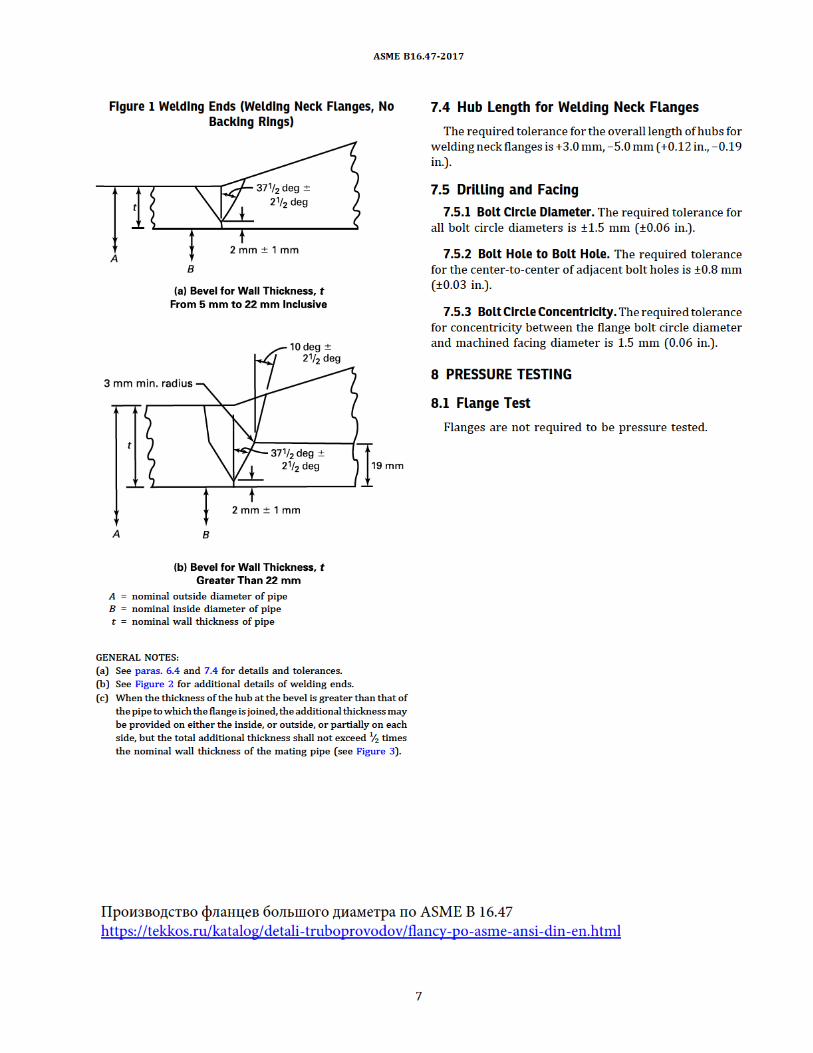

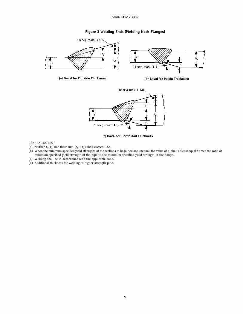
Figure 3 Welding Ends (Welding Neck Flanges)
GENERAL NOTES:(a) Neither t1, t2, nor their sum (t1 + t2) shall exceed 0.5t.(b) When the minimum specified yield strengths of the sections to be joined are unequal, the value of tD shall at least equal t times the ratio of
minimum specified yield strength of the pipe to the minimum specified yield strength of the flange.(c) Welding shall be in accordance with the applicable code.(d) Additional thickness for welding to higher strength pipe.
ASME B16.47-2017
9

Table 1 List of Material Specifications
MaterialGroup
NominalDesignation
Applicable ASTM SpecificationsForgings Castings Plates
1.1 C–Si A105 A216 Gr. WCB A515 Gr. 701.1 C–Mn–Si A350 Gr. LF2 … A516 Gr. 701.1 C–Mn–Si … … A537 Cl. 11.1 C–Mn–Si–V A350 Gr. LF6 Cl. 1 … …1.1 31∕2Ni A350 Gr. LF3 … …
1.2 C–Mn–Si … A216 Gr. WCC …1.2 C–Mn–Si … A352 Gr. LCC …1.2 C–Mn–Si–V A350 Gr. LF6 Cl. 2 … …1.2 21∕2Ni … A352 Gr. LC2 A203 Gr. B1.2 31∕2Ni … A352 Gr. LC3 A203 Gr. E
1.3 C–Si … A352 Gr. LCB A515 Gr. 651.3 C–Mn–Si … … A516 Gr. 651.3 21∕2Ni … … A203 Gr. A1.3 31∕2Ni … … A203 Gr. D1.3 C–1∕2Mo … A217 Gr. WC1 …
1.3 C–1∕2Mo … A352 Gr. LC1 …1.4 C–Si … … A515 Gr. 601.4 C–Mn–Si A350 Gr. LF1 Cl. 1 … A516 Gr. 601.5 C–1∕2Mo A182 Gr. F1 … A204 Gr. A1.5 C–1∕2Mo … … A204 Gr. B
1.7 1∕2Cr–1∕2Mo A182 Gr. F2 … …1.7 Ni–1∕2Cr–1∕2Mo … A217 Gr. WC4 …1.7 3∕4Ni–3∕4Cr–1Mo … A217 Gr. WC5 …1.9 11∕4Cr–1∕2Mo … A217 Gr. WC6 …1.9 11∕4Cr–1∕2Mo–Si A182 Gr. F11 Cl. 2 … A387 Gr. 11 Cl. 2
1.10 21∕4Cr–1Mo A182 Gr. F22 Cl. 3 A217 Gr. WC9 A387 Gr. 22 Cl. 21.11 C–1∕2Mo … … A240 Gr. C1.13 5Cr–1∕2Mo A182 Gr. F5a A217 Gr. C5 …1.14 9Cr–1Mo A182 Gr. F9 A217 Gr. C12 …1.15 9Cr–1Mo–V A182 Gr. F91 A217 Gr. C12A A387 Gr. 91 Cl. 2
1.17 1Cr–1∕2Mo A182 Gr. F12 Cl. 2 … …1.17 5Cr–1∕2Mo A182 Gr. F5 … …1.18 9Cr–2W–V A182 Gr. F92 … …2.1 18Cr–8Ni A182 Gr. F304 A351 Gr. CF3 A240 Gr. 3042.1 18Cr–8Ni A182 Gr. F304H A351 Gr. CF8 A240 Gr. 304H
2.2 16Cr–12Ni–2Mo A182 Gr. F316 A351 Gr. CF3M A240 Gr. 3162.2 16Cr–12Ni–2Mo A182 Gr. F316H A351 Gr. CF8M A240 Gr. 316H2.2 18Cr–13Ni–3Mo A182 Gr. F317 … A240 Gr. 3172.2 19Cr–10Ni–3Mo … A351 Gr. CG8M …2.3 18Cr–8Ni A182 Gr. F304L … A240 Gr. 304L
2.3 16Cr–12Ni–2Mo A182 Gr. F316L … A240 Gr. 316L2.3 18Cr–13Ni–3Mo A182 Gr. F317L … …2.4 18Cr–10Ni–Ti A182 Gr. F321 … A240 Gr. 321
ASME B16.47-2017
10

Table 1 List of Material Specifications (Cont'd)
MaterialGroup
NominalDesignation
Applicable ASTM SpecificationsForgings Castings Plates
2.4 18Cr–10Ni–Ti A182 Gr. F321H … A240 Gr. 321H2.5 18Cr–10Ni–Cb A182 Gr. F347 … A240 Gr. 347
2.5 18Cr–10Ni–Cb A182 Gr. F347H … A240 Gr. 347H2.5 18Cr–10Ni–Cb A182 Gr. F348 … A240 Gr. 3482.5 18Cr–10Ni–Cb A182 Gr. F348H … A240 Gr. 348H2.6 23Cr–12Ni … … A240 Gr. 309H2.7 25Cr–20Ni A182 Gr. F310 … A240 Gr. 310H
2.8 20Cr–18Ni–6Mo A182 Gr. F44 A351 Gr. CK3MCuN A240 Gr. S312542.8 22Cr–5Ni–3Mo–N A182 Gr. F51 … A240 Gr. S318032.8 25Cr–7Ni–4Mo–N A182 Gr. F53 … A240 Gr. S327502.8 24Cr–10Ni–4Mo–V … A351 Gr. CE8MN …2.8 25Cr–5Ni–2Mo–3Cu … A995 Gr. CD4MCu …
2.8 25Cr–7Ni–3.5Mo–W–Cb … A995 Gr. CD3MWCuN …2.8 25Cr–7Ni–3.5Mo–N–Cu–W A182 Gr. F55 … A240 Gr. S327602.9 23Cr–12Ni … … A240 Gr. 309S2.9 25Cr–20Ni … … A240 Gr. 310S2.10 25Cr–12Ni … A351 Gr. CH8 …
2.10 25Cr–12Ni … A351 Gr. CH20 …2.11 18Cr–10Ni–Cb … A351 Gr. CF8C …2.12 25Cr–20Ni … A351 Gr. CK20 …
ASME B16.47-2017
11
Производство фланцев большого диаметра по ASME B 16.47https://tekkos.ru/katalog/detali-truboprovodov/flancy-po-asme-ansi-din-en.html

Table 2 List of Bolting Specifications (Applicable ASTM Specifications)
Bolting MaterialsHigh Strength [Note (1)] Intermediate Strength [Note (2)] Low Strength [Note (3)]
Spec.-Grade Notes Spec.-Grade Notes Spec.-Grade NotesA193-B7 … A193-B5 … A193-B8 Cl. 1 (4)A193-B16 … A193-B6 … A193-B8C Cl. 1 (4)
A193-B6X … A193-B8M Cl. 1 (4)A320-L7 (5) A193-B7M … A193-B8T Cl. 1 (4)A320-L7A (5)A320-L7B (5) A193-B8 Cl. 2, 2B (6) A193-B8A (4)A320-L7C (5) A193-B8C Cl. 2 (6) A193-B8CA …A320-L43 (5) A193-B8M Cl. 2, 2B, 2C (6) A193-B8MA …
A193-B8T Cl. 2 (6) A193-B8TA (4)A354-BC …A354-BD … A320-B8 Cl. 2 (6) A307-B (7)
A320-B8C Cl. 2 (6)A540-B21 … A320-B8F Cl. 2 (6) A320-B8 Cl. 1 (4)A540-B22 … A320-B8M Cl. 2 (6) A320-B8C Cl. 1 (4)A540-B23 … A320-B8T Cl. 2 (6) A320-B8M Cl. 1 (4)A540-B24 … A320-B8T Cl. 1 (4)
A449 (8)A453-651 (9)A453-660 (9)
GENERAL NOTES:(a) Bolting material shall not be used beyond temperature limits specified in the governing code.(b) ASME Boiler and Pressure Vessel Code, Section II materials, which alsomeet the requirements of the listed ASTM specifications, may also be
used.(c) Repair welding of bolting material is prohibited.
NOTES:(1) These bolting materials may be used with all listed materials and gaskets. See para. 5.3.2.(2) These boltingmaterials may be usedwith all listedmaterials and gaskets, provided it has been verified that a sealed joint can bemaintained
under rated working pressure and temperature. See para. 5.3.3.(3) Theseboltingmaterialsmaybeusedwith all listedmaterials, but are limited toClasses 75, 150, and300 joints. Seepara. 5.3.4. Seepara. 5.4 for
recommended gasket practices.(4) This austenitic stainless material has been carbide solution treated but not strain hardened. Use A194 nuts of corresponding material.(5) This ferritic material is intended for low temperature service. Use A194 Gr. 4 or Gr. 7 nuts.(6) This austenitic stainless material has been carbide solution treated and strain hardened. Use A194 nuts of corresponding material.(7) This carbon steel fastener shall not be used above 200°C (400°F) or below −29°C (−20°F). See also Note (3). Bolts with drilled or undersized
heads shall not be used.(8) Acceptable nuts for usewithquenchedand temperedbolts areA194Gr. 2 andGr. 2H.Mechanical property requirements for studs shall be the
same as those for bolts.(9) This special alloy is intended for high temperature service with austentic stainless steel.
ASME B16.47-2017
12

Table 3 Pressure–Temperature Ratings for Group 1.1 Materials
NominalDesignation Forgings Castings Plates
C–Si A105 [Note (1)] A216 Gr. WCB [Note (1)] A515 Gr. 70 [Note (1)]C–Mn–Si A350 Gr. LF2 [Note (1)] … A516 Gr. 70 [Notes (1), (2)]C–Mn–Si … … A537 Cl. 1 [Note (3)]C–Mn–Si–V A350 Gr. LF6 Cl. 1 [Note (4)] … …31∕2Ni A350 Gr. LF3 … …
Temperature, °CWorking Pressure by Classes, bar
75 150 300 400 600 900−29 to 38 9.8 19.6 51.1 68.1 102.1 153.2
50 9.6 19.2 50.1 66.8 100.2 150.4100 8.8 17.7 46.6 62.1 93.2 139.8150 7.9 15.8 45.1 60.1 90.2 135.2200 6.9 13.8 43.8 58.4 87.6 131.4
250 6.0 12.1 41.9 55.9 83.9 125.8300 5.1 10.2 39.8 53.1 79.6 119.5325 4.6 9.3 38.7 51.6 77.4 116.1350 3.1 8.4 37.6 50.1 75.1 112.7375 … 7.4 36.4 48.5 72.7 109.1
400 … 6.5 34.7 46.3 69.4 104.2425 … 5.5 28.8 38.4 57.5 86.3450 … 4.6 23.0 30.7 46.0 69.0475 … 3.7 17.4 23.2 34.9 52.3500 … 2.8 11.8 15.7 23.5 35.3
538 … 1.4 5.9 7.9 11.8 17.7
NOTES:(1) Upon prolonged exposure to temperatures above 425°C, the carbide phase of steel may be converted to graphite. Permissible, but not
recommended for prolonged use above 425°C.(2) Not to be used over 455°C.(3) Not to be used over 370°C.(4) Not to be used over 260°C.
ASME B16.47-2017
13

Table 4 Pressure–Temperature Ratings for Group 1.2 Materials
NominalDesignation Forgings Castings Plates
C–Mn–Si … A216 Gr. WCC [Note (1)] …C–Mn–Si … A352 Gr. LCC [Note (2)] …C–Mn–Si–V A350 Gr. LF6 Cl. 2 [Note (3)] … …21∕2Ni … A352 Gr. LC2 A203 Gr. B [Note (1)]31∕2Ni … A352 Gr. LC3 [Note (2)] A203 Gr. E [Note (1)]
Temperature, °CWorking Pressure by Classes, bar
75 150 300 400 600 900−29 to 38 9.9 19.8 51.7 68.9 103.4 155.1
50 9.8 19.5 51.7 68.9 103.4 155.1100 8.8 17.7 51.5 68.7 103.0 154.6150 7.9 15.8 50.2 66.8 100.3 150.5200 6.9 13.8 48.6 64.8 97.2 145.8
250 6.0 12.1 46.3 61.7 92.7 139.0300 5.1 10.2 42.9 57.0 85.7 128.6325 4.6 9.3 41.4 55.0 82.6 124.0350 3.1 8.4 40.0 53.4 80.0 120.1375 … 7.4 37.8 50.4 75.7 113.5
400 … 6.5 34.7 46.3 69.4 104.2425 … 5.5 28.8 38.4 57.5 86.3450 … 4.6 23.0 30.7 46.0 69.0475 … 3.7 17.1 22.8 34.2 51.3500 … 2.8 11.6 15.4 23.2 34.7
538 … 1.4 5.9 7.9 11.8 17.7
NOTES:(1) Upon prolonged exposure to temperatures above 425°C, the carbide phase of steel may be converted to graphite. Permissible, but not
recommended for prolonged use above 425°C.(2) Not to be used over 340°C.(3) Not to be used over 260°C.
ASME B16.47-2017
14

Table 5 Pressure–Temperature Ratings for Group 1.3 Materials
NominalDesignation Forgings Castings Plates
C–Si … A352 Gr. LCB [Note (1)] A515 Gr. 65 [Note (2)]C–Mn–Si … … A516 Gr. 65 [Notes (2), (3)]C–1∕2Mo … A217 Gr. WC1 [Notes (4)–(6)] …C-1∕2Mo … A352 Gr. LC1 [Note (1)] …21∕2Ni … … A203 Gr. A [Note (2)]31∕2Ni … … A203 Gr. D [Note (2)]
Temperature, °CWorking Pressure by Classes, bar
75 150 300 400 600 900−29 to 38 9.2 18.4 48.0 64.0 96.0 144.1
50 9.1 18.2 47.5 63.3 94.9 142.4100 8.7 17.4 45.3 60.5 90.7 136.0150 7.9 15.8 43.9 58.6 87.9 131.8
200 6.9 13.8 42.5 56.7 85.1 127.6250 6.0 12.1 40.8 54.4 81.6 122.3300 5.1 10.2 38.7 51.6 77.4 116.1325 4.6 9.3 37.6 50.1 75.2 112.7350 3.1 8.4 36.4 48.5 72.8 109.2375 … 7.4 35.0 46.6 69.9 104.9
400 … 6.5 32.6 43.5 65.2 97.9425 … 5.5 27.3 36.4 54.6 81.9450 … 4.6 21.6 28.8 43.2 64.8475 … 3.7 15.7 20.9 31.3 47.0500 … 2.8 11.1 14.8 22.1 33.2
538 … 1.4 5.9 7.9 11.8 17.7
NOTES:(1) Not to be used over 340°C.(2) Upon prolonged exposure to temperatures above 425°C, the carbide phase of steel may be converted to graphite. Permissible, but not
recommended for prolonged use above 425°C.(3) Not to be used over 455°C.(4) Upon prolonged exposure to temperatures above 465°C, the carbide phase of steel may be converted to graphite. Permissible, but not
recommended for prolonged use above 465°C.(5) Use normalized and tempered material only.(6) The deliberate addition of any element not listed in ASTMA217, Table 1 is prohibited, except that calcium (Ca) andmanganese (Mn)may be
added for deoxidation.
ASME B16.47-2017
15

Table 6 Pressure–Temperature Ratings for Group 1.4 Materials
NominalDesignation Forgings Castings Plates
C–Si … … A515 Gr. 60 [Note (1)]C–Mn–Si A350 Gr. LF1 Cl. 1 [Note (1)] … A516 Gr. 60 [Notes (1), (2)]
Temperature, °CWorking Pressure by Classes, bar
75 150 300 400 600 900−29 to 38 8.2 16.3 42.6 56.7 85.1 127.7
50 8.0 16.0 41.8 55.7 83.5 125.3100 7.4 14.9 38.8 51.8 77.7 116.5150 7.2 14.4 37.6 50.1 75.1 112.7200 6.9 13.8 36.4 48.5 72.8 109.2
250 6.0 12.1 34.9 46.6 69.8 104.7300 5.1 10.2 33.2 44.2 66.4 99.5325 4.6 9.3 32.2 43.0 64.5 96.7350 3.1 8.4 31.2 41.7 62.5 93.7375 … 7.4 30.4 40.5 60.7 91.1
400 … 6.5 29.3 39.1 58.7 88.0425 … 5.5 25.8 34.4 51.5 77.3450 … 4.6 21.4 28.5 42.7 64.1475 … 3.7 14.1 18.8 28.2 42.3500 … 2.8 10.3 13.7 20.6 30.9
538 … 1.4 5.9 7.9 11.8 17.7
NOTES:(1) Upon prolonged exposure to temperatures above 425°C, the carbide phase of steel may be converted to graphite. Permissible, but not
recommended for prolonged use above 425°C.(2) Not to be used over 455°C.
ASME B16.47-2017
16
Производство фланцев большого диаметра по ASME B 16.47https://tekkos.ru/katalog/detali-truboprovodov/flancy-po-asme-ansi-din-en.html

Table 7 Pressure–Temperature Ratings for Group 1.5 Materials
NominalDesignation Forgings Castings PlatesC–1∕2Mo A182 Gr. F1 [Note (1)] … A204 Gr. A [Note (1)]C–1∕2Mo … … A204 Gr. B [Note (1)]
Working Pressure by Classes, barTemperature, °C 75 150 300 400 600 900
−29 to 38 9.2 18.4 48.0 64.0 96.0 144.150 9.2 18.4 48.0 64.0 96.0 144.1100 8.8 17.7 47.9 63.9 95.9 143.8150 7.9 15.8 47.3 63.1 94.7 142.0200 6.9 13.8 45.8 61.1 91.6 137.4
250 6.0 12.1 44.5 59.3 89.0 133.5300 5.1 10.2 42.9 57.0 85.7 128.6325 4.6 9.3 41.4 55.0 82.6 124.0350 3.1 8.4 40.3 53.6 80.4 120.7375 … 7.4 38.9 51.6 77.6 116.5
400 … 6.5 36.5 48.9 73.3 109.8425 … 5.5 35.2 46.5 70.0 105.1450 … 4.6 33.7 45.1 67.7 101.4475 … 3.7 31.7 42.3 63.4 95.1500 … 2.8 24.1 32.1 48.1 72.2
538 … 1.4 11.3 15.1 22.7 34.0
NOTE: (1)Uponprolonged exposure to temperatures above465°C, the carbidephaseof carbon-molybdenumsteelmaybe converted to graphite.Permissible, but not recommended for prolonged use above 465°C.
ASME B16.47-2017
17

Table 8 Pressure–Temperature Ratings for Group 1.7 Materials
Nominal Designation Forgings Castings Plates1∕2Cr–1∕2Mo A182 Gr. F2 [Note (1)] … …Ni–1∕2Cr–1∕2Mo … A217 Gr. WC4 [Notes (1)–(3)] …3∕4Ni–3∕4Cr–1Mo … A217 Gr. WC5 [Notes (2), (3)] …
Working Pressure by Classes, barTemperature, °C 75 150 300 400 600 900
−29 to 38 9.9 19.8 51.7 68.9 103.4 155.150 9.8 19.5 51.7 68.9 103.4 155.1100 8.8 17.7 51.5 68.7 103.0 154.6150 7.9 15.8 50.3 66.8 100.3 150.6200 6.9 13.8 48.6 64.8 97.2 145.8
250 6.0 12.1 46.3 61.7 92.7 139.0300 5.1 10.2 42.9 57.0 85.7 128.6325 4.6 9.3 41.4 55.0 82.6 124.0350 3.1 8.4 40.3 53.6 80.4 120.7375 … 7.4 38.9 51.6 77.6 116.5
400 … 6.5 36.5 48.9 73.3 109.8425 … 5.5 35.2 46.5 70.0 105.1450 … 4.6 33.7 45.1 67.7 101.4475 … 3.7 31.7 42.3 63.4 95.1500 … 2.8 26.7 35.6 53.4 80.1
538 … 1.4 13.9 18.6 27.9 41.8550 … … 12.6 16.8 25.2 37.8575 … … 7.2 9.6 14.4 21.5
NOTES:(1) Not to be used over 538°C.(2) Use normalized and tempered material only.(3) The deliberate addition of any element not listed in ASTMA217, Table 1 is prohibited, except that calcium (Ca) andmanganese (Mn)may be
added for deoxidation.
ASME B16.47-2017
18

Table 9 Pressure–Temperature Ratings for Group 1.9 Materials
NominalDesignation Forgings Castings Plates
11∕4Cr–1∕2Mo … A217 Gr. WC6 [Notes (1), (3), (4)] …11∕4Cr–1∕2Mo–Si A182 Gr. F11 Cl. 2 [Notes (1), (2)] … A387 Gr. 11 Cl. 2 [Note (2)]
Working Pressure by Classes, barTemperature, °C 75 150 300 400 600 900
−29 to 38 9.9 19.8 51.7 68.9 103.4 155.150 9.8 19.5 51.7 68.9 103.4 155.1100 8.8 17.7 51.5 68.6 103.0 154.4150 7.9 15.8 49.7 66.3 99.5 149.2200 6.9 13.8 48.0 63.9 95.9 143.9
250 6.0 12.1 46.3 61.7 92.7 139.0300 5.1 10.2 42.9 57.0 85.7 128.6325 4.6 9.3 41.4 55.0 82.6 124.0350 3.1 8.4 40.3 53.6 80.4 120.7375 … 7.4 38.9 51.6 77.6 116.5
400 … 6.5 36.5 48.9 73.3 109.8425 … 5.5 35.2 46.5 70.0 105.1450 … 4.6 33.7 45.1 67.7 101.4475 … 3.7 31.7 42.3 63.4 95.1500 … 2.8 25.7 34.3 51.5 77.2
538 … 1.4 14.9 19.9 29.8 44.7550 … … 12.7 16.9 25.4 38.1575 … … 8.8 11.7 17.6 26.4600 … … 6.1 8.1 12.2 18.3625 … … 4.3 5.7 8.5 12.8
650 … … 2.8 3.8 5.7 8.5
NOTES:(1) Use normalized and tempered material only.(2) Permissible, but not recommended for prolonged use above 590°C.(3) Not to be used over 590°C.(4) The deliberate addition of any element not listed in ASTMA217, Table 1 is prohibited, except that calcium (Ca) andmanganese (Mn)may be
added for deoxidation.
ASME B16.47-2017
19
Производство фланцев большого диаметра по ASME B 16.47https://tekkos.ru/katalog/detali-truboprovodov/flancy-po-asme-ansi-din-en.html

Table 10 Pressure–Temperature Ratings for Group 1.10 Materials
NominalDesignation Forgings Castings Plates21∕4Cr–1Mo A182 Gr. F22 Cl. 3 [Note (1)] A217 Gr. WC9 [Notes (2), (3), (4)] A387 Gr. 22 Cl. 2 [Note (1)]
Working Pressure by Classes, barTemperature, °C 75 150 300 400 600 900
−29 to 38 9.9 19.8 51.7 68.9 103.4 155.150 9.8 19.5 51.7 68.9 103.4 155.1100 8.8 17.7 51.5 68.7 103.0 154.6150 7.9 15.8 50.3 66.8 100.3 150.6200 6.9 13.8 48.6 64.8 97.2 145.8
250 6.0 12.1 46.3 61.7 92.7 139.0300 5.1 10.2 42.9 57.0 85.7 128.6325 4.6 9.3 41.4 55.0 82.6 124.0350 3.1 8.4 40.3 53.6 80.4 120.7375 0.0 7.4 38.9 51.6 77.6 116.5
400 … 6.5 36.5 48.9 73.3 109.8425 … 5.5 35.2 46.5 70.0 105.1450 … 4.6 33.7 45.1 67.7 101.4475 … 3.7 31.7 42.3 63.4 95.1500 … 2.8 28.2 37.6 56.5 84.7
538 … 1.4 18.4 24.6 36.9 55.3550 … … 15.6 20.8 31.3 46.9575 … … 10.5 14.0 21.1 31.6600 … … 6.9 9.2 13.8 20.7625 … … 4.5 6.0 8.9 13.4
650 … … 2.8 3.8 5.7 8.5
NOTES:(1) Permissible, but not recommended for prolonged use above 590°C.(2) Use normalized and tempered material only.(3) Not to be used over 590°C.(4) The deliberate addition of any element not listed in ASTMA217, Table 1 is prohibited, except that calcium (Ca) andmanganese (Mn)may be
added for deoxidation.
ASME B16.47-2017
20
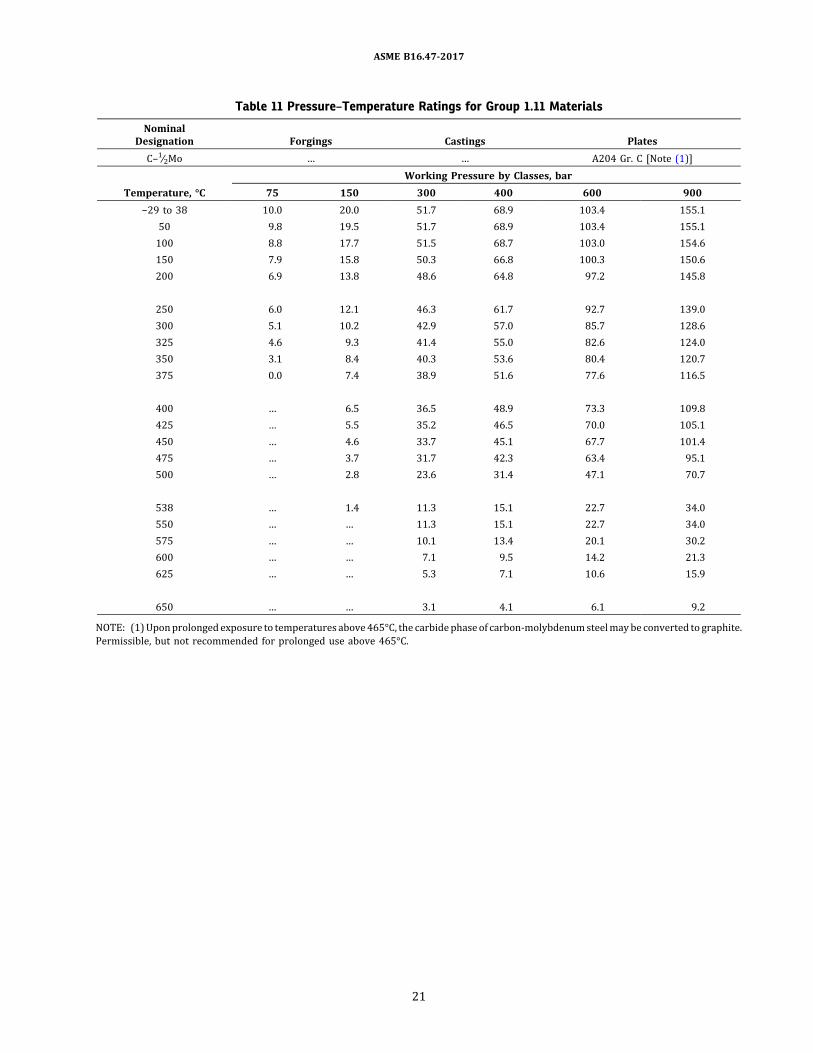
Table 11 Pressure–Temperature Ratings for Group 1.11 Materials
NominalDesignation Forgings Castings PlatesC–1∕2Mo … … A204 Gr. C [Note (1)]
Working Pressure by Classes, barTemperature, °C 75 150 300 400 600 900
−29 to 38 10.0 20.0 51.7 68.9 103.4 155.150 9.8 19.5 51.7 68.9 103.4 155.1100 8.8 17.7 51.5 68.7 103.0 154.6150 7.9 15.8 50.3 66.8 100.3 150.6200 6.9 13.8 48.6 64.8 97.2 145.8
250 6.0 12.1 46.3 61.7 92.7 139.0300 5.1 10.2 42.9 57.0 85.7 128.6325 4.6 9.3 41.4 55.0 82.6 124.0350 3.1 8.4 40.3 53.6 80.4 120.7375 0.0 7.4 38.9 51.6 77.6 116.5
400 … 6.5 36.5 48.9 73.3 109.8425 … 5.5 35.2 46.5 70.0 105.1450 … 4.6 33.7 45.1 67.7 101.4475 … 3.7 31.7 42.3 63.4 95.1500 … 2.8 23.6 31.4 47.1 70.7
538 … 1.4 11.3 15.1 22.7 34.0550 … … 11.3 15.1 22.7 34.0575 … … 10.1 13.4 20.1 30.2600 … … 7.1 9.5 14.2 21.3625 … … 5.3 7.1 10.6 15.9
650 … … 3.1 4.1 6.1 9.2
NOTE: (1)Uponprolonged exposure to temperatures above465°C, the carbidephaseof carbon-molybdenumsteelmaybe converted to graphite.Permissible, but not recommended for prolonged use above 465°C.
ASME B16.47-2017
21

Table 12 Pressure–Temperature Ratings for Group 1.13 Materials
NominalDesignation Forgings Castings Plates5Cr–1∕2Mo A182 Gr. F5a A217 Gr. C5 [Notes (1), (2)] …
Working Pressure by Classes, barTemperature, °C 75 150 300 400 600 900
−29 to 38 10.0 20.0 51.7 68.9 103.4 155.150 9.8 19.5 51.7 68.9 103.4 155.1100 8.8 17.7 51.5 68.7 103.0 154.6150 7.9 15.8 50.3 66.8 100.3 150.6200 6.9 13.8 48.6 64.8 97.2 145.8
250 6.0 12.1 46.3 61.7 92.7 139.0300 5.1 10.2 42.9 57.0 85.7 128.6325 4.6 9.3 41.4 55.0 82.6 124.0350 3.1 8.4 40.3 53.6 80.4 120.7375 0.0 7.4 38.9 51.6 77.6 116.5
400 … 6.5 36.5 48.9 73.3 109.8425 … 5.5 35.2 46.5 70.0 105.1450 … 4.6 33.7 45.1 67.7 101.4475 … 3.7 27.9 37.1 55.7 83.6500 … 2.8 21.4 28.5 42.8 64.1
538 … 1.4 13.7 18.3 27.4 41.1550 … … 12.0 16.1 24.1 36.1575 … … 8.9 11.8 17.8 26.7600 … … 6.2 8.3 12.5 18.7625 … … 4.0 5.3 8.0 12.0
650 … … 2.4 3.2 4.7 7.1
NOTES:(1) Use normalized and tempered material only.(2) The deliberate addition of any element not listed in ASTMA217, Table 1 is prohibited, except that calcium (Ca) andmanganese (Mn)may be
added for deoxidation.
ASME B16.47-2017
22

Table 13 Pressure–Temperature Ratings for Group 1.14 Materials
NominalDesignation Forgings Castings Plates9Cr–1Mo A182 Gr. F9 A217 Gr. C12 [Notes (1), (2)] …
Working Pressure by Classes, barTemperature, °C 75 150 300 400 600 900
−29 to 38 10.0 20.0 51.7 68.9 103.4 155.150 9.8 19.5 51.7 68.9 103.4 155.1100 8.8 17.7 51.5 68.7 103.0 154.6150 7.9 15.8 50.3 66.8 100.3 150.6200 6.9 13.8 48.6 64.8 97.2 145.8
250 6.0 12.1 46.3 61.7 92.7 139.0300 5.1 10.2 42.9 57.0 85.7 128.6325 4.6 9.3 41.4 55.0 82.6 124.0350 3.1 8.4 40.3 53.6 80.4 120.7375 … 7.4 38.9 51.6 77.6 116.5
400 … 6.5 36.5 48.9 73.3 109.8425 … 5.5 35.2 46.5 70.0 105.1450 … 4.6 33.7 45.1 67.7 101.4475 … 3.7 31.7 42.3 63.4 95.1500 … 2.8 28.2 37.6 56.5 84.7
538 … 1.4 17.5 23.3 35.0 52.5550 … … 15.0 20.0 30.0 45.0575 … … 10.5 13.9 20.9 31.4600 … … 7.2 9.6 14.4 21.5625 … … 5.0 6.6 9.9 14.9
650 … … 3.5 4.7 7.1 10.6
NOTES:(1) Use normalized and tempered material only.(2) The deliberate addition of any element not listed in ASTMA217, Table 1 is prohibited, except that calcium (Ca) andmanganese (Mn)may be
added for deoxidation.
ASME B16.47-2017
23

Table 14 Pressure–Temperature Ratings for Group 1.15 Materials
NominalDesignation Forgings Castings Plates9Cr–1Mo–V A182 Gr. F91 A217 Gr. C12A [Note (1)] A387 Gr. 91 Cl. 2
Working Pressure by Classes, barTemperature, °C 75 150 300 400 600 900
−29 to 38 10.0 20.0 51.7 68.9 103.4 155.150 9.8 19.5 51.7 68.9 103.4 155.1100 8.8 17.7 51.5 68.7 103.0 154.6150 7.9 15.8 50.3 66.8 100.3 150.6200 6.9 13.8 48.6 64.8 97.2 145.8
250 6.0 12.1 46.3 61.7 92.7 139.0300 5.1 10.2 42.9 57.0 85.7 128.6325 4.6 9.3 41.4 55.0 82.6 124.0350 3.1 8.4 40.3 53.6 80.4 120.7375 … 7.4 38.9 51.6 77.6 116.5
400 … 6.5 36.5 48.9 73.3 109.8425 … 5.5 35.2 46.5 70.0 105.1450 … 4.6 33.7 45.1 67.7 101.4475 … 3.7 31.7 42.3 63.4 95.1500 … 2.8 28.2 37.6 56.5 84.7
538 … 1.4 25.2 33.4 50.0 75.2550 … … 25.0 33.3 49.8 74.8575 … … 24.0 31.9 47.9 71.8600 … … 19.5 26.0 39.0 58.5625 … … 14.6 19.5 29.2 43.8
650 … 9.9 13.2 19.9 29.8
NOTE: (1) The deliberate addition of any element not listed in ASTM A217, Table 1 is prohibited, except that calcium (Ca) and manganese (Mn)may be added for deoxidation.
ASME B16.47-2017
24

Table 15 Pressure–Temperature Ratings for Group 1.17 Materials
NominalDesignation Forgings Castings Plates1Cr–1∕2Mo A182 Gr. F12 Cl. 2 [Notes (1), (2)] … …5Cr–1∕2Mo A182 Gr. F5 … …
Working Pressure by Classes, barTemperature, °C 75 150 300 400 600 900
−29 to 38 9.9 19.8 51.7 68.9 103.4 155.150 9.8 19.5 51.5 68.7 103.0 154.5100 8.8 17.7 50.4 67.3 100.9 151.3150 7.9 15.8 48.2 64.2 96.4 144.5200 6.9 13.8 46.3 61.7 92.5 138.8
250 6.0 12.1 44.8 59.8 89.6 134.5300 5.1 10.2 42.9 57.0 85.7 128.6325 4.6 9.3 41.4 55.0 82.6 124.0350 3.1 8.4 40.3 53.6 80.4 120.7375 … 7.4 38.9 51.6 77.6 116.5
400 … 6.5 36.5 48.9 73.3 109.8425 … 5.5 35.2 46.5 70.0 105.1450 … 4.6 33.7 45.1 67.7 101.4475 … 3.7 27.9 37.1 55.7 83.6500 … 2.8 21.4 28.5 42.8 64.1
538 … 1.4 13.7 18.3 27.4 41.1550 … … 12.0 16.1 24.1 36.1575 … … 8.8 11.7 17.6 26.4600 … … 6.1 8.1 12.1 18.2625 … … 4.0 5.3 8.0 12.0
650 … … 2.4 3.2 4.7 7.1
NOTES:(1) Use normalized and tempered material only.(2) Permissible, but not recommended for prolonged use above 590°C.
ASME B16.47-2017
25

Table 16ð17Þ Pressure–Temperature Ratings for Group 1.18 Materials
NominalDesignation Forgings Castings Plates9Cr–2W–V A182 Gr. F92 [Note (1)] … …
Working Pressure by Classes, barTemperature, °C 75 150 300 400 600 900
−29 to 38 10.0 20.0 51.7 68.9 103.4 155.150 9.8 19.5 51.7 68.9 103.4 155.1100 8.9 17.7 51.5 68.7 103.0 154.6150 7.9 15.8 50.3 66.8 100.3 150.6200 6.9 13.8 48.6 64.8 97.2 145.8
250 6.1 12.1 46.3 61.7 92.7 139.0300 5.1 10.2 42.9 57.0 85.7 128.6325 4.7 9.3 41.4 55.0 82.6 124.0350 4.2 8.4 40.3 53.6 80.4 120.7375 … 7.4 38.9 51.6 77.6 116.5
400 … 6.5 36.5 48.9 73.3 109.8425 … 5.5 35.2 46.5 70.0 105.1450 … 4.6 33.7 45.1 67.7 101.4475 … 3.7 31.7 42.3 63.4 95.1500 … 2.8 28.2 37.6 56.5 84.7
538 … 1.4 25.2 33.4 50.0 75.2550 … … 25.0 33.3 49.8 74.8575 … … 24.0 31.9 47.9 71.8600 … … 21.6 28.6 42.9 64.2625 … … 18.3 24.3 36.6 54.9
650 … … 13.2 18.9 26.5 39.7
NOTE: (1) Applications above 620°C are limited to tubing of maximum outside diameter of 31∕2 in.
ASME B16.47-2017
26

Table 17 Pressure–Temperature Ratings for Group 2.1 Materials
NominalDesignation Forgings Castings Plates18Cr–8Ni A182 Gr. F304 [Note (1)] A351 Gr. CF3 [Note (2)] A240 Gr. 304 [Note (1)]18Cr–8Ni A182 Gr. F304H A351 Gr. CF8 [Note (1)] A240 Gr. 304H
Working Pressure by Classes, barTemperature, °C 75 150 300 400 600 900
−29 to 38 9.5 19.0 49.6 66.2 99.3 148.950 9.2 18.3 47.8 63.8 95.6 143.5100 7.8 15.7 40.9 54.5 81.7 122.6150 7.1 14.2 37.0 49.3 74.0 111.0200 6.6 13.2 34.5 46.0 69.0 103.4
250 6.0 12.1 32.5 43.3 65.0 97.5300 5.1 10.2 30.9 41.2 61.8 92.7325 4.6 9.3 30.2 40.3 60.4 90.7350 3.1 8.4 29.6 39.5 59.3 88.9375 … 7.4 29.0 38.7 58.1 87.1
400 … 6.5 28.4 37.9 56.9 85.3425 … 5.5 28.0 37.3 56.0 84.0450 … 4.6 27.4 36.5 54.8 82.2475 … 3.7 26.9 35.9 53.9 80.8500 … 2.8 26.5 35.3 53.0 79.5
538 … 1.4 24.4 32.6 48.9 73.3550 … … 23.6 31.4 47.1 70.7575 … … 20.8 27.8 41.7 62.5600 … … 16.9 22.5 33.8 50.6625 … … 13.8 18.4 27.6 41.4
650 … … 11.3 15.0 22.5 33.8675 … … 9.3 12.5 18.7 28.0700 … … 8.0 10.7 16.1 24.1725 … … 6.8 9.0 13.5 20.3750 … … 5.8 7.7 11.6 17.3
775 … … 4.6 6.2 9.0 13.7800 … … 3.5 4.8 7.0 10.5816 … … 2.8 3.8 5.9 8.6
NOTES:(1) At temperatures over 538°C, use only when the carbon content is 0.04% or higher.(2) Not to be used over 425°C.
ASME B16.47-2017
27

Table 18 Pressure–Temperature Ratings for Group 2.2 Materials
NominalDesignation Forgings Castings Plates
16Cr–12Ni–2Mo A182 Gr. F316 [Note (1)] A351 Gr. CF3M [Note (2)] A240 Gr. 316 [Note (1)]16Cr–12Ni–2Mo A182 Gr. F316H A351 Gr. CF8M [Note (1)] A240 Gr. 316H18Cr–13Ni–3Mo A182 Gr. F317 [Note (1)] … A240 Gr. 317 [Note (1)]19Cr–10Ni–3Mo … A351 Gr. CG8M [Note (3)] …
Working Pressure by Classes, barTemperature, °C 75 150 300 400 600 900
−29 to 38 9.5 19.0 49.6 66.2 99.3 148.950 9.2 18.4 48.1 64.2 96.2 144.3100 8.1 16.2 42.2 56.3 84.4 126.6150 7.4 14.8 38.5 51.3 77.0 115.5
200 6.8 13.7 35.7 47.6 71.3 107.0250 6.0 12.1 33.4 44.5 66.8 100.1300 5.1 10.2 31.6 42.2 63.2 94.9325 4.6 9.3 30.9 41.2 61.8 92.7350 3.1 8.4 30.3 40.4 60.7 91.0
375 … 7.4 29.9 39.8 59.8 89.6400 … 6.5 29.4 39.3 58.9 88.3425 … 5.5 29.1 38.9 58.3 87.4450 … 4.6 28.8 38.5 57.7 86.5475 … 3.7 28.7 38.2 57.3 86.0
500 … 2.8 28.2 37.6 56.5 84.7538 … 1.4 25.2 33.4 50.0 75.2550 … … 25.0 33.3 49.8 74.8575 … … 24.0 31.9 47.9 71.8600 … … 19.9 26.5 39.8 59.7
625 … … 15.8 21.1 31.6 47.4650 … … 12.7 16.9 25.3 38.0675 … … 10.3 13.8 20.6 31.0700 … … 8.4 11.2 16.8 25.1725 … … 7.0 9.3 14.0 21.0
750 … … 5.9 7.8 11.7 17.6775 … … 4.6 6.2 9.0 13.7800 … … 3.5 4.8 7.0 10.5816 … … 2.8 3.8 5.9 8.6
NOTES:(1) At temperatures over 538°C, use only when the carbon content is 0.04% or higher.(2) Not to be used over 455°C.(3) Not to be used over 538°C.
ASME B16.47-2017
28

Table 19 Pressure–Temperature Ratings for Group 2.3 Materials
NominalDesignation Forgings Castings Plates
18Cr–8Ni A182 Gr. F304L [Note (1)] … A240 Gr. 304L [Note (1)]16Cr–12Ni–2Mo A182 Gr. F316L … A240 Gr. 316L18Cr–13Ni–3Mo A182 Gr. F317L … …
Working Pressure by Classes, barTemperature, °C 75 150 300 400 600 900
−29 to 38 7.9 15.9 41.4 55.2 82.7 124.150 7.7 15.3 40.0 53.4 80.0 120.1100 6.7 13.3 34.8 46.4 69.6 104.4150 6.0 12.0 31.4 41.9 62.8 94.2200 5.6 11.2 29.2 38.9 58.3 87.5
250 5.3 10.5 27.5 36.6 54.9 82.4300 5.0 10.0 26.1 34.8 52.1 78.2325 4.6 9.3 25.5 34.0 51.0 76.4350 3.1 8.4 25.1 33.4 50.1 75.2375 … 7.4 24.8 33.0 49.5 74.3
400 … 6.5 24.3 32.4 48.6 72.9425 … 5.5 23.9 31.8 47.7 71.6450 … 4.6 23.4 31.2 46.8 70.2
NOTE: (1) Not to be used over 425°C.
ASME B16.47-2017
29

Table 20 Pressure–Temperature Ratings for Group 2.4 Materials
NominalDesignation Forgings Castings Plates18Cr–10Ni–Ti A182 Gr. F321 [Note (1)] … A240 Gr. 321 [Note (1)]18Cr–10Ni–Ti A182 Gr. F321H [Note (2)] … A240 Gr. 321H [Note (2)]
Working Pressure by Classes, barTemperature, °C 75 150 300 400 600 900
−29 to 38 9.5 19.0 49.6 66.2 99.3 148.950 9.3 18.6 48.6 64.7 97.1 145.7100 8.5 17.0 44.2 59.0 88.5 132.7150 7.9 15.7 41.0 54.6 82.0 122.9200 6.9 13.8 38.3 51.1 76.6 114.9
250 6.0 12.1 36.0 48.0 72.0 108.1300 5.1 10.2 34.1 45.5 68.3 102.4325 4.6 9.3 33.3 44.4 66.6 99.9350 3.1 8.4 32.6 43.5 65.2 97.8375 … 7.4 32.0 42.7 64.1 96.1
400 … 6.5 31.6 42.1 63.2 94.8425 … 6.5 31.1 41.5 62.3 93.4450 … 4.6 30.8 41.1 61.7 92.5475 … 3.7 30.5 40.7 61.1 91.6500 … 2.8 28.2 37.6 56.5 84.7
538 … 1.4 25.2 33.4 50.0 75.2550 … … 25.0 33.3 49.8 74.8575 … … 24.0 31.9 47.9 71.8600 … … 20.3 27.0 40.5 60.8625 … … 15.8 21.1 31.6 47.4
650 … … 12.6 16.9 25.3 37.9675 … … 9.9 13.2 19.8 29.6700 … … 7.9 10.5 15.8 23.7725 … … 6.3 8.5 12.7 19.0750 … … 5.0 6.7 10.0 15.0
775 … … 4.0 5.3 8.0 11.9800 … … 3.1 4.2 6.3 9.4816 … … 2.6 3.5 5.2 7.8
NOTES:(1) Not to be used over 538°C.(2) At temperatures over 538°C, use only if the material is heat treated by heating to a minimum temperature of 1 095°C.
ASME B16.47-2017
30

Table 21 Pressure–Temperature Ratings for Group 2.5 Materials
NominalDesignation Forgings Castings Plates
18Cr–10Ni–Cb A182 Gr. F347 [Note (1)] … A240 Gr. 347 [Note (1)]18Cr–10Ni–Cb A182 Gr. F347H [Note (2)] … A240 Gr. 347H [Note (2)]18Cr–10Ni–Cb A182 Gr. F348 [Note (1)] … A240 Gr. 348 [Note (1)]18Cr–10Ni–Cb A182 Gr. F348H [Note (2)] … A240 Gr. 348H [Note (2)]
Working Pressure by Classes, barTemperature, °C 75 150 300 400 600 900
−29 to 38 9.5 19.0 49.6 66.2 99.3 148.950 9.3 18.7 48.8 65.0 97.5 146.3100 8.7 17.4 45.3 60.4 90.6 135.9150 7.9 15.8 42.5 56.6 84.9 127.4200 6.9 13.8 39.9 53.3 79.9 119.8
250 6.0 12.1 37.8 50.4 75.6 113.4300 5.1 10.2 36.1 48.1 72.2 108.3325 4.6 9.3 35.4 47.1 70.7 106.1350 3.1 8.4 34.8 46.3 69.5 104.3375 … 7.4 34.2 45.6 68.4 102.6
400 … 6.5 33.9 45.2 67.8 101.7425 … 5.5 33.6 44.8 67.2 100.8450 … 4.6 33.5 44.6 66.9 100.4475 … 3.7 31.7 42.3 63.4 95.1500 … 2.8 28.2 37.6 56.5 84.7
538 … 1.4 25.2 33.4 50.0 75.2550 … … 25.0 33.3 49.8 74.8575 … … 24.0 31.9 47.9 71.8600 … … 21.6 28.6 42.9 64.2625 … … 18.3 24.3 36.6 54.9
650 … … 14.1 18.9 28.1 42.5675 … … 12.4 16.9 25.2 37.6700 … … 10.1 13.4 20.0 29.8725 … … 7.9 10.5 15.4 23.2750 … … 5.9 7.9 11.7 17.6775 … … 4.6 6.2 9.0 13.7800 … … 3.5 4.8 7.0 10.5816 … … 2.8 3.8 5.9 8.6
NOTES:(1) Not to be used over 538°C.(2) For temperatures over 538°C, use only if the material is heat treated by heating to a minimum temperature of 1 095°C.
ASME B16.47-2017
31
Производство фланцев большого диаметра по ASME B 16.47https://tekkos.ru/katalog/detali-truboprovodov/flancy-po-asme-ansi-din-en.html

Table 22 Pressure–Temperature Ratings for Group 2.6 Materials
NominalDesignation Forgings Castings Plates23Cr–12Ni … … A240 Gr. 309H
Working Pressure by Classes, barTemperature, °C 75 150 300 400 600 900
−29 to 38 9.5 19.0 49.6 66.2 99.3 148.950 9.3 18.5 48.3 64.4 96.6 144.9100 8.3 16.5 43.1 57.5 86.2 129.3150 7.7 15.3 40.0 53.3 80.0 120.0200 6.9 13.8 37.8 50.3 75.5 113.3
250 6.0 12.1 36.1 48.1 72.1 108.2300 5.1 10.2 34.8 46.4 69.6 104.4325 4.6 9.3 34.2 45.7 68.5 102.7350 3.1 8.4 33.8 45.1 67.6 101.4375 … 7.4 33.4 44.5 66.8 100.1
400 … 6.5 33.1 44.1 66.1 99.2425 … 5.5 32.6 43.5 65.3 97.9450 … 4.6 32.2 42.9 64.4 96.5475 … 3.7 31.7 42.3 63.4 95.1500 … 2.8 28.2 37.6 56.5 84.7
538 … 1.4 25.2 33.4 50.0 75.2550 … … 25.0 33.3 49.8 74.8575 … … 22.2 29.6 44.4 66.5600 … … 16.8 22.4 33.5 50.3625 … … 12.5 16.7 25.0 37.5
650 … … 9.4 12.5 18.7 28.1675 … … 7.2 9.6 14.5 21.7700 … … 5.5 7.3 11.0 16.5725 … … 4.3 5.8 8.7 13.0750 … … 3.4 4.6 6.8 10.2
775 … … 2.7 3.6 5.4 8.1800 … … 2.1 2.8 4.2 6.3816 … … 1.8 2.4 3.5 5.3
ASME B16.47-2017
32

Table 23 Pressure–Temperature Ratings for Group 2.7 Materials
NominalDesignation Forgings Castings Plates25Cr–20Ni A182 Gr. F310 [Notes (1), (2)] … A240 Gr. 310H
Working Pressure by Classes, barTemperature, °C 75 150 300 400 600 900
−29 to 38 9.5 19.0 49.6 66.2 99.3 148.950 9.3 18.5 48.4 64.5 96.7 145.1100 8.3 16.6 43.4 57.9 86.8 130.2150 7.7 15.3 40.0 53.3 80.0 120.0200 6.9 13.8 37.6 50.1 75.2 112.8
250 6.0 12.1 35.8 47.7 71.5 107.3300 5.1 10.2 34.5 45.9 68.9 103.4325 4.6 9.3 33.9 45.2 67.7 101.6350 3.1 8.4 33.3 44.4 66.6 99.9375 … 7.4 32.9 43.8 65.7 98.6
400 … 6.5 32.4 43.2 64.8 97.3425 … 5.5 32.1 42.8 64.2 96.4450 … 4.6 31.7 42.2 63.4 95.1475 … 3.7 31.2 41.7 62.5 93.7500 … 2.8 28.2 37.6 56.5 84.7
538 … 1.4 25.2 33.4 50.0 75.2550 … … 25.0 33.3 49.8 74.8575 … … 22.2 29.6 44.4 66.5600 … … 16.8 22.4 33.5 50.3625 … … 12.5 16.7 25.0 37.5
650 … … 9.4 12.5 18.7 28.1675 … … 7.2 9.6 14.5 21.7700 … … 5.5 7.3 11.0 16.5725 … … 4.3 5.8 8.7 13.0750 … … 3.4 4.6 6.8 10.2
775 … … 2.7 3.5 5.3 8.0800 … … 2.1 2.8 4.1 6.2816 … … 1.8 2.4 3.5 5.3
NOTES:(1) At temperatures over 538°C, use only when the carbon content is 0.04% or higher.(2) Service temperatures of 565°C and above should be used only when assurance is provided that grain size is not finer than ASTM 6.
ASME B16.47-2017
33

Table 24 Pressure–Temperature Ratings for Group 2.8 Materials
NominalDesignation Forgings Castings Plates
20Cr–18Ni–6Mo A182 Gr. F44 A351 Gr. CK3MCuN A240 Gr. S3125422Cr–5Ni–3Mo–N A182 Gr. F51 [Note (1)] … A240 Gr. S31803 [Note (1)]25Cr–7Ni–4Mo–N A182 Gr. F53 [Note (1)] … A240 Gr. S32750 [Note (1)]24Cr–10Ni–4Mo–V … A351 Gr. CE8MN [Note (1)] …25Cr–5Ni–2Mo–3Cu … A995 Gr. CD4MCu [Note (1)] …25Cr–7Ni–3.5Mo–W–Cb … A995 Gr. CD3MWCuN [Note (1)] …25Cr–7Ni–3.5Mo–N–Cu–W A182 Gr. F55 [Note (1)] … A240 Gr. S32760 [Note (1)]
Working Pressure by Classes, barTemperature, °C 75 150 300 400 600 900
−29 to 38 10.0 20.0 51.7 68.9 103.4 155.150 9.8 19.5 51.7 68.9 103.4 155.1100 8.8 17.7 50.7 67.5 101.3 152.0150 7.9 15.8 45.9 61.2 91.9 137.8200 6.9 13.8 42.7 56.9 85.3 128.0
250 6.0 12.1 40.5 53.9 80.9 121.4300 5.1 10.2 38.9 51.8 77.7 116.6325 4.6 9.3 38.2 50.9 76.3 114.5350 3.1 8.4 37.6 50.2 75.3 112.9375 … 7.4 37.4 49.8 74.7 112.1
400 … 6.5 36.5 48.9 73.3 109.8
NOTE: (1) This steel may become brittle after service at moderately elevated temperatures. Not to be used over 315°C.
ASME B16.47-2017
34

Table 25 Pressure–Temperature Ratings for Group 2.9 Materials
NominalDesignation Forgings Castings Plates23Cr–12Ni … … A240 Gr. 309S [Notes (1)–(3)]25Cr–20Ni … … A240 Gr. 310S [Notes (1)–(3)]
Working Pressure by Classes, barTemperature, °C 75 150 300 400 600 900
−29 to 38 9.5 19.0 49.6 66.2 99.3 148.950 9.3 18.5 48.3 64.4 96.6 144.9100 8.3 16.5 43.1 57.5 86.2 129.3150 7.7 15.3 40.0 53.3 80.0 120.0200 6.9 13.8 37.6 50.1 75.2 112.8
250 6.0 12.1 35.8 47.7 71.5 107.3300 5.1 10.2 34.5 45.9 68.9 103.4325 4.6 9.3 33.9 45.2 67.7 101.6350 3.1 8.4 33.3 44.4 66.6 99.9375 … 7.4 32.9 43.8 65.7 98.6
400 … 6.5 32.4 43.2 64.8 97.3425 … 5.5 32.1 42.8 64.2 96.4450 … 4.6 31.7 42.2 63.4 95.1475 … 3.7 31.2 41.7 62.5 93.7500 … 2.8 28.2 37.6 56.5 84.7
538 … 1.4 23.4 31.2 46.8 70.2550 … … 20.5 27.3 41.0 61.5575 … … 15.1 20.1 30.2 45.3600 … … 11.0 14.7 22.1 33.1625 … … 8.1 10.9 16.3 24.4
650 … … 5.8 7.8 11.6 17.4675 … … 3.7 4.9 7.4 11.1700 … … 2.2 2.9 4.3 6.5725 … … 1.4 1.8 2.7 4.1750 … … 1.0 1.4 2.1 3.1
775 … … 0.8 1.1 1.6 2.5800 … … 0.6 0.8 1.2 1.8816 … … 0.5 0.6 0.9 1.4
NOTES:(1) At temperatures over 538°C, use only when the carbon content is 0.04% or higher.(2) At temperatures above 538°C, use only if thematerial is solution heat treated to theminimum temperature specified in the specification, but
not lower than 1 035°C, and quenching in water or rapidly cooling by other means.(3) This material should be used for service temperatures 565°C and above only when assurance is provided that grain size is not finer than
ASTM 6.
ASME B16.47-2017
35

Table 26 Pressure–Temperature Ratings for Group 2.10 Materials
NominalDesignation Forgings Castings Plates25Cr–12Ni … A351 Gr. CH8 [Note (1)] …25Cr–12Ni … A351 Gr. CH20 [Note (1)] …
Working Pressure by Classes, barTemperature, °C 75 150 300 400 600 900
−29 to 38 8.9 17.8 46.3 61.8 92.7 139.050 8.5 17.0 44.5 59.3 89.0 133.4100 7.2 14.4 37.5 50.0 75.1 112.6150 6.7 13.4 34.9 46.5 69.8 104.7200 6.4 12.9 33.5 44.7 67.1 100.6
250 6.0 12.1 32.6 43.5 65.2 97.8300 5.1 10.2 31.7 42.3 63.4 95.2325 4.6 9.3 31.2 41.6 62.4 93.6350 3.1 8.4 30.6 40.8 61.2 91.7375 … 7.4 29.8 39.8 59.7 89.5
400 … 6.5 29.1 38.8 58.2 87.3425 … 5.5 28.3 37.8 56.7 85.0450 … 4.6 27.6 36.8 55.2 82.8475 … 3.7 26.7 35.6 53.5 80.2500 … 2.8 25.8 34.5 51.7 77.5
538 … 1.4 23.3 31.1 46.6 70.0550 … … 21.9 29.2 43.8 65.7575 … … 18.5 24.6 37.0 55.5600 … … 14.5 19.4 29.0 43.5625 … … 11.4 15.2 22.8 34.3
650 … … 8.9 11.9 17.8 26.7675 … … 7.0 9.3 14.0 20.9700 … … 5.7 7.6 11.3 17.0725 … … 4.6 6.1 9.1 13.7750 … … 3.5 4.7 7.0 10.5
775 … … 2.6 3.4 5.1 7.7800 … … 2.0 2.7 4.0 6.1816 … … 1.9 2.5 3.8 5.7
NOTE: (1) At temperatures over 538°C, use only when the carbon content is 0.04% or higher.
ASME B16.47-2017
36

Table 27 Pressure–Temperature Ratings for Group 2.11 Materials
NominalDesignation Forgings Castings Plates18Cr–10Ni–Cb … A351 Gr. CF8C [Note (1)] …
Working Pressure by Classes, barTemperature, °C 75 150 300 400 600 900
−29 to 38 9.5 19.0 49.6 66.2 99.3 148.950 9.3 18.7 48.8 65.0 97.5 146.3100 8.7 17.4 45.3 60.4 90.6 135.9150 7.9 15.8 42.5 56.6 84.9 127.4200 6.9 13.8 39.9 53.3 79.9 119.8
250 6.0 12.1 37.8 50.4 75.6 113.4300 5.1 10.2 36.1 48.1 72.2 108.3325 4.6 9.3 35.4 47.1 70.7 106.1350 3.1 8.4 34.8 46.3 69.5 104.3375 … 7.4 34.2 45.6 68.4 102.6
400 … 6.5 33.9 45.2 67.8 101.7425 … 5.5 33.6 44.8 67.2 100.8450 … 4.6 33.5 44.6 66.9 100.4475 … 3.7 31.7 42.3 63.4 95.1500 … 2.8 28.2 37.6 56.5 84.7
538 … 1.4 25.2 33.4 50.0 75.2550 … … 25.0 33.3 49.8 74.8575 … … 24.0 31.9 47.9 71.8600 … … 19.8 26.4 39.6 59.4625 … … 13.9 18.5 27.7 41.6
650 … … 10.3 13.7 20.6 30.9675 … … 8.0 10.6 15.9 23.9700 … … 5.6 7.5 11.2 16.8725 … … 4.0 5.3 8.0 11.9
750 … … 3.1 4.1 6.2 9.3775 … … 2.5 3.3 4.9 7.4800 … … 2.0 2.7 4.0 6.1816 … … 1.9 2.5 3.8 5.7
NOTE: (1) At temperatures over 538°C, use only when the carbon content is 0.04% or higher.
ASME B16.47-2017
37
Производство фланцев большого диаметра по ASME B 16.47https://tekkos.ru/katalog/detali-truboprovodov/flancy-po-asme-ansi-din-en.html

Table 28 Pressure–Temperature Ratings for Group 2.12 Materials
NominalDesignation Forgings Castings Plates25Cr–20Ni … A351 Gr. CK20 [Note (1)] …
Working Pressure by Classes, barTemperature, °C 75 150 300 400 600 900
−29 to 38 8.9 17.8 46.3 61.8 92.7 139.050 8.5 17.0 44.5 59.3 89.0 133.4100 7.2 14.4 37.5 50.0 75.1 112.6150 6.7 13.4 34.9 46.5 69.8 104.7200 6.4 12.9 33.5 44.7 67.1 100.6
250 6.0 12.1 32.6 43.5 65.2 97.8300 5.1 10.2 31.7 42.3 63.4 95.2325 4.6 9.3 31.2 41.6 62.4 93.6350 3.1 8.4 30.6 40.8 61.2 91.7375 … 7.4 29.8 39.8 59.7 89.5
400 … 6.5 29.1 38.8 58.2 87.3425 … 5.5 28.3 37.8 56.7 85.0450 … 4.6 27.6 36.8 55.2 82.8475 … 3.7 26.7 35.6 53.5 80.2500 … 2.8 25.8 34.5 51.7 77.5
538 … 1.4 23.3 31.1 46.6 70.0550 … … 22.9 30.6 45.9 68.8575 … … 21.7 28.9 43.3 65.0600 … … 19.4 25.9 38.8 58.2625 … … 16.8 22.4 33.7 50.5
650 … … 14.1 18.8 28.1 42.2675 … … 11.5 15.4 23.0 34.6700 … … 8.8 11.7 17.5 26.3725 … … 6.3 8.5 12.7 19.0750 … … 4.5 6.0 8.9 13.4
775 … … 3.1 4.2 6.3 9.4800 … … 2.3 3.1 4.6 6.9816 … … 1.9 2.5 3.8 5.7
NOTE: (1) At temperatures over 538°C, use only when the carbon content is 0.04% or higher.
ASME B16.47-2017
38

Table 29 Dimensions of Ring-Joint Facings
Nominal Pipe Size for ClassGrooveNumber
Groove Dimensions Diameterof RaisedPortion, K300 400 600 900
PitchDiameter, P Depth, E Width, F
Radius atBottom, R
26 26 26 … R93 749.30 12.70 19.84 1.5 81028 28 28 … R94 800.10 12.70 19.84 1.5 86130 30 30 … R95 857.25 12.70 19.84 1.5 91732 32 32 … R96 914.40 14.27 23.01 1.5 98434 34 34 … R97 965.20 14.27 23.01 1.5 1 03536 36 36 … R98 1 022.35 14.27 23.01 1.5 1 092… … … 26 R100 749.30 17.48 30.18 2.3 832… … … 28 R101 800.10 17.48 33.32 2.3 889… … … 30 R102 857.25 17.48 33.32 2.3 946… … … 32 R103 914.40 17.48 33.32 2.3 1 003… … … 34 R104 965.20 20.62 36.53 2.3 1 067… … … 36 R105 1 022.35 20.62 36.53 2.3 1 124
TolerancesE (depth) +0.4, −0.0F (width) ±0.2P (pitch diameter) ±0.13R (radius at bottom) +0.8, −0.0 for R ≤ 2
±0.8 for R > 223 deg angle ±1∕2 deg
GENERAL NOTES:(a) Dimensions are in millimeters.(b) Ring-joint gaskets are not contemplated for NPS 38 and larger flanges.(c) For facing requirements for flanges, see para. 6.1.(d) See para. 4.2 for marking requirements.
NOTE: (1) Height of raised portion is equal to the depth of groove dimensionE, but is not subjected to the tolerances forE. Full face contourmaybe used.
Table 30 Permissible Imperfections in Flange Facing Finish
Nominal Pipe Size
Maximum Radial Projectionof Imperfections That AreNo Deeper Than Bottom
of Serration, mm
Maximum Depth and RadialProjection of ImperfectionsThat Are Deeper ThanBottom of Serration, mm
26–36 12.5 6.038–48 14.0 7.050–60 16.0 8.0
GENERAL NOTE: See para. 6.1.5.
ASME B16.47-2017
39


Table 42ð17Þ Flange Bolting Dimensional Recommendations
Product Carbon Steel Alloy SteelBolts smaller than 3∕4 in. ASME B18.2.1, square or heavy hex head ASME B18.2.1, heavy hex headBolts equal to or larger than 3∕4 in. ASME B18.2.1, square or heavy hex head ASME B18.2.1, heavy hex headNuts smaller than 3∕4 in. ASME B18.2.2, heavy hex ASME B18.2.2, heavy hexNuts equal to or larger than 3∕4 in. ASME B18.2.2, hex or heavy hex ASME B18.2.2, heavy hexStud bolts ASME B18.31.2 ASME B18.31.2External threads ASME B1.1, Cl. 2A course series ASME B1.1, Cl. 2A course series up through 1 in.;
eight thread series for larger boltsInternal threads ASME B1.1, Cl. 2B course series ASME B1.1, Cl. 2B course series up through 1 in.;
eight thread series for larger bolts
ASME B16.47-2017
51
Производство фланцев большого диаметра по ASME B 16.47https://tekkos.ru/katalog/detali-truboprovodov/flancy-po-asme-ansi-din-en.html

MANDATORY APPENDIX IPRESSURE–TEMPERATURE RATINGS AND DIMENSIONAL DATAFOR CLASSES 75, 150, 300, 400, 600, AND 900 FLANGES IN
U.S. CUSTOMARY UNITS
The pressure–temperature ratings for the materialslisted in Table 1, and covered by this Standard are aslisted in Tables 3 through 28 and Tables I-1 through I-26 of Mandatory Appendix I.Tables 3 through 28 have pressure–temperature
ratings using bar units for pressure (1 bar = 100 kPa)and degrees Celsius units for temperature.
Tables I-1 through I-26 of Mandatory Appendix I havecoterminous pressure–temperature ratings using poundsper square inch (psi) units for pressure and degreesFahrenheit units for temperature.All tabulated pressures are gage pressures.Figures I-1 through I-3 and Tables I-27 through I-39
included in thisMandatoryAppendixprovidedimensionaldata in U.S. Customary units for Classes 75, 150, 300, 400,600, and 900 flanges.
ASME B16.47-2017
52

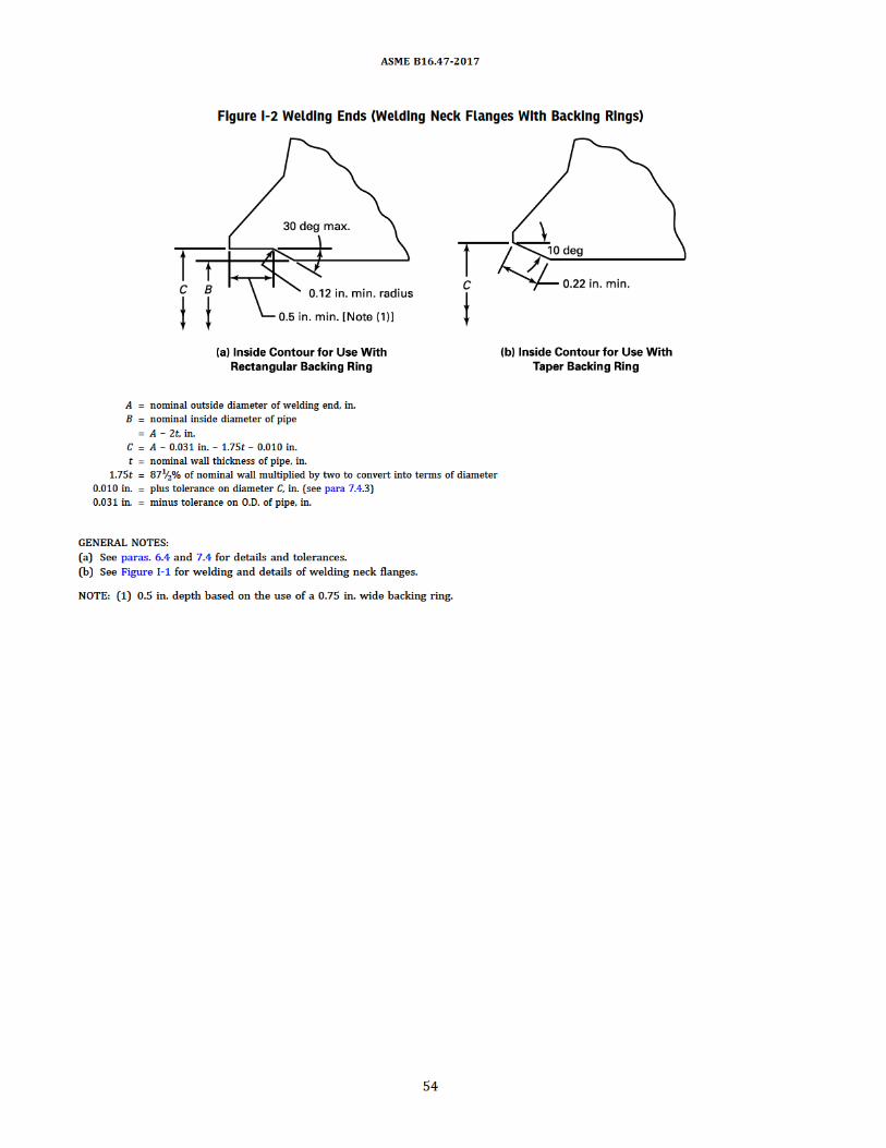

Figure I-3 Welding Ends (Welding Neck Flanges)
GENERAL NOTES:(a) Neither t1, t2, nor their sum (t1 + t2) shall exceed 0.5t.(b) When the minimum specified yield strengths of the sections to be joined are unequal, the value of tD shall at least equal t times the ratio of
minimum specified yield strength of the pipe to the minimum specified yield strength of the flange.(c) Welding shall be in accordance with the applicable code.(d) Additional thickness for welding to higher strength pipe.
ASME B16.47-2017
55
Производство фланцев большого диаметра по ASME B 16.47https://tekkos.ru/katalog/detali-truboprovodov/flancy-po-asme-ansi-din-en.html

Table I-1 Pressure–Temperature Ratings for Group 1.1 Materials
NominalDesignation Forgings Castings Plates
C–Si A105 [Note (1)] A216 Gr. WCB [Note (1)] A515 Gr. 70 [Note (1)]C–Mn–Si A350 Gr. LF2 [Note (1)] … A516 Gr. 70 [Notes (1), (2)]C–Mn–Si … … A537 Cl. 1 [Note (3)]C–Mn–Si–V A350 Gr. LF6 Cl. 1 [Note (4)] … …31∕2Ni A350 Gr. LF3 … …
Working Pressure by Classes, psigTemperature, °F 75 150 300 400 600 900
−20 to 100 140 285 740 985 1,480 2,220200 130 260 680 905 1,360 2,035300 115 230 655 870 1,310 1,965400 100 200 635 845 1,265 1,900500 85 170 605 805 1,205 1,810
600 70 140 570 755 1,135 1,705650 60 125 550 730 1,100 1,650700 … 110 530 710 1,060 1,590750 … 95 505 675 1,015 1,520800 … 80 410 550 825 1,235
850 … 65 320 425 640 955900 … 50 230 305 460 690950 … 35 135 185 275 4101,000 … 20 85 115 170 255
NOTES:(1) Upon prolonged exposure to temperatures above 800°F, the carbide phase of steel may be converted to graphite. Permissible, but not
recommended for prolonged use above 800°F.(2) Not to be used over 850°F.(3) Not to be used over 700°F.(4) Not to be used over 500°F.
ASME B16.47-2017
56

Table I-2 Pressure–Temperature Ratings for Group 1.2 Materials
NominalDesignation Forgings Castings Plates
C–Mn–Si … A216 Gr. WCC [Note (1)] …C–Mn–Si … A352 Gr. LCC [Note (2)] …C–Mn–Si–V A350 Gr. LF6 Cl. 2 [Note (3)] … …21∕2Ni … A352 Gr. LC2 A203 Gr. B [Note (1)]31∕2Ni … A352 Gr. LC3 [Note (2)] A203 Gr. E [Note (1)]
Working Pressure by Classes, psigTemperature, °F 75 150 300 400 600 900
−20 to 100 145 290 750 1,000 1,500 2,250200 130 260 750 1,000 1,500 2,250300 115 230 730 970 1,455 2,185400 100 200 705 940 1,405 2,110500 85 170 665 885 1,330 1,995
600 70 140 605 805 1,210 1,815650 60 125 590 785 1,175 1,765700 … 110 555 740 1,110 1,665750 … 95 505 675 1,015 1,520800 … 80 410 550 825 1,235
850 … 65 320 425 640 955900 … 50 225 295 445 670950 … 35 135 185 275 4101,000 … 20 85 115 170 255
NOTES:(1) Upon prolonged exposure to temperatures above 800°F, the carbide phase of steel may be converted to graphite. Permissible, but not
recommended for prolonged use above 800°F.(2) Not to be used over 650°F.(3) Not to be used over 500°F.
ASME B16.47-2017
57

Table I-3 Pressure–Temperature Ratings for Group 1.3 Materials
NominalDesignation Forgings Castings Plates
C–Si … A352 Gr. LCB [Note (1)] A515 Gr. 65 [Note (2)]C–Mn–Si … … A516 Gr. 65 [Notes (2), (3)]C–1∕2Mo … A217 Gr. WC1 [Notes (4)–(6)] …C–1∕2Mo … A352 Gr. LC1 [Note (1)] …21∕2Ni … … A203 Gr. A [Note (2)]31∕2Ni … … A203 Gr. D [Note (2)]
Working Pressure by Classes, psigTemperature, °F 75 150 300 400 600 900
−20 to 100 135 265 695 930 1,395 2,090200 125 255 660 880 1,320 1,980300 115 230 640 850 1,275 1,915400 100 200 615 820 1,230 1,845500 85 170 585 780 1,175 1,760
600 70 140 550 735 1,105 1,655650 60 125 535 710 1,065 1,600700 … 110 510 685 1,025 1,535750 … 95 475 635 955 1,430800 … 80 390 520 780 1,175
850 … 65 300 400 595 895900 … 50 200 270 405 605950 … 35 135 185 275 4101,000 … 20 85 115 170 255
NOTES:(1) Not to be used over 650°F.(2) Upon prolonged exposure to temperatures above 800°F, the carbide phase of steel may be converted to graphite. Permissible, but not
recommended for prolonged use above 800°F.(3) Not to be used over 850°F.(4) Upon prolonged exposure to temperatures above 875°F, the carbide phase of steel may be converted to graphite. Permissible, but not
recommended for prolonged use above 875°F.(5) Use normalized and tempered material only.(6) The deliberate addition of any element not listed in ASTMA217, Table 1 is prohibited, except that calcium (Ca) andmanganese (Mn)may be
added for deoxidation.
ASME B16.47-2017
58

Table I-4 Pressure–Temperature Ratings for Group 1.4 Materials
NominalDesignation Forgings Castings Plates
C–Si … … A515 Gr. 60 [Note (1)]C–Mn–Si A350 Gr. LF1 Cl. 1 [Note (1)] … A516 Gr. 60 [Notes (1), (2)]
Working Pressure by Classes, psigTemperature, °F 75 150 300 400 600 900
−20 to 100 120 235 615 825 1,235 1,850200 110 215 565 755 1,130 1,695300 105 210 545 725 1,090 1,635400 100 200 525 700 1,055 1,580500 85 170 500 670 1,005 1,505
600 70 140 475 630 945 1,420650 60 125 455 610 915 1,370700 … 110 440 590 885 1,325750 … 95 430 570 855 1,285800 … 80 370 495 740 1,110
850 … 65 300 400 595 895900 … 50 170 230 345 515950 … 35 135 185 275 4101,000 … 20 85 115 170 255
NOTES:(1) Upon prolonged exposure to temperature above 800°F, the carbide phase of steel may be converted to graphite. Permissible, but not
recommended for prolonged use above 800°F.(2) Not to be used over 850°F.
ASME B16.47-2017
59

Table I-5 Pressure–Temperature Ratings for Group 1.5 Materials
NominalDesignation Forgings Castings PlatesC–1∕2Mo A182 Gr. F1 [Note (1)] … A204 Gr. A [Note (1)]C–1∕2Mo … … A204 Gr. B [Note (1)]
Working Pressure by Classes, psigTemperature, °F 75 150 300 400 600 900
−20 to 100 135 265 695 930 1,395 2,090200 130 260 695 930 1,395 2,090300 115 230 685 915 1,375 2,060400 100 200 660 885 1,325 1,985500 85 170 640 855 1,285 1,925
600 70 140 605 805 1,210 1,815650 60 125 590 785 1,175 1,765700 … 110 570 755 1,135 1,705750 … 95 530 710 1,065 1,595800 … 80 510 675 1,015 1,525
850 … 65 485 650 975 1,460900 … 50 450 600 900 1,350950 … 35 280 375 560 8451,000 … 20 165 220 330 495
NOTE: (1)Uponprolonged exposure to temperatures above875°F, the carbidephaseof carbon-molybdenumsteelmaybe converted to graphite.Permissible, but not recommended for prolonged use above 875°F.
ASME B16.47-2017
60

Table I-6 Pressure–Temperature Ratings for Group 1.7 Materials
NominalDesignation Forgings Castings Plates
1∕2Cr–1∕2Mo A182 Gr. F2 [Note (1)] … …Ni–1∕2Cr–1∕2Mo … A217 Gr. WC4 [Notes (1)–(3)] …3∕4Ni–3∕4Cr–1Mo … A217 Gr. WC5 [Notes (2), (3)] …
Working Pressure by Classes, psigTemperature, °F 75 150 300 400 600 900
−20 to 100 145 290 750 1,000 1,500 2,250200 130 260 750 1,000 1,500 2,250300 115 230 730 970 1,455 2,185400 100 200 705 940 1,410 2,115500 85 170 665 885 1,330 1,995
600 70 140 605 805 1,210 1,815650 60 125 590 785 1,175 1,765700 … 110 570 755 1,135 1,705750 … 95 530 710 1,065 1,595800 … 80 510 675 1,015 1,525
850 … 65 485 650 975 1,460900 … 50 450 600 900 1,350950 … 35 315 420 630 9451,000 … 20 200 270 405 6051,050 … … 160 210 315 475
NOTES:(1) Not to be used over 1,000°F.(2) Use normalized and tempered material only.(3) The deliberate addition of any element not listed in ASTMA217, Table 1 is prohibited, except that calcium (Ca) andmanganese (Mn)may be
added for deoxidation.
ASME B16.47-2017
61

Table I-7 Pressure–Temperature Ratings for Group 1.9 Materials
NominalDesignation Forgings Castings Plates
11∕4Cr–1∕2Mo … A217 Gr. WC6 [Notes (1), (3), (4)] …11∕4Cr–1∕2Mo-Si A182 Gr. F11 Cl. 2 [Notes (1), (2)] … A387 Gr. 11 Cl. 2 [Note (2)]
Working Pressure by Classes, psigTemperature, °F 75 150 300 400 600 900
−20 to 100 145 290 750 1,000 1,500 2,250200 130 260 750 1,000 1,500 2,250300 115 230 720 965 1,445 2,165400 100 200 695 925 1,385 2,080500 85 170 665 885 1,330 1,995
600 70 140 605 805 1,210 1,815650 60 125 590 785 1,175 1,765700 … 110 570 755 1,135 1,705750 … 95 530 710 1,065 1,595800 … 80 510 675 1,015 1,525
850 … 65 485 650 975 1,460900 … 50 450 600 900 1,350950 … 35 320 425 640 9551,000 … 20 215 290 430 6501,050 … … 145 190 290 430
1,100 … … 95 130 190 2901,150 … … 65 85 130 1951,200 … … 40 55 80 125
NOTES:(1) Use normalized and tempered material only.(2) Permissible, but not recommended for prolonged use above 1,100°F.(3) Not to be used over 1,100°F.(4) The deliberate addition of any element not listed in ASTMA217, Table 1 is prohibited, except that calcium (Ca) andmanganese (Mn)may be
added for deoxidation.
ASME B16.47-2017
62
Производство фланцев большого диаметра по ASME B 16.47https://tekkos.ru/katalog/detali-truboprovodov/flancy-po-asme-ansi-din-en.html

Table I-8 Pressure–Temperature Ratings for Group 1.10 Materials
NominalDesignation Forgings Castings Plates21∕4Cr–1Mo A182 Gr. F22 Cl. 3 [Note (1)] A217 Gr. WC9 [Notes (2), (3), (4)] A387 Gr. 22 Cl. 2 [Note (1)]
Working Pressure by Classes, psigTemperature, °F 75 150 300 400 600 900
−20 to 100 145 290 750 1,000 1,500 2,250200 130 260 750 1,000 1,500 2,250300 115 230 730 970 1,455 2,185400 100 200 705 940 1,410 2,115500 85 170 665 885 1,330 1,995
600 70 140 605 805 1,210 1,815650 60 125 590 785 1,175 1,765700 … 110 570 755 1,135 1,705750 … 95 530 710 1,065 1,595800 … 80 510 675 1,015 1,525
850 … 65 485 650 975 1,460900 … 50 450 600 900 1,350950 … 35 385 515 755 1,1601,000 … 20 265 355 535 8001,050 … … 175 235 350 525
1,100 … … 110 145 220 3301,150 … … 70 90 135 2051,200 … … 40 55 80 125
NOTES:(1) Permissible, but not recommended for prolonged use above 1,100°F.(2) Use normalized and tempered material only.(3) Not to be used over 1,100°F.(4) The deliberate addition of any element not listed in ASTMA217, Table 1 is prohibited, except that calcium (Ca) andmanganese (Mn)may be
added for deoxidation.
ASME B16.47-2017
63

Table I-9 Pressure–Temperature Ratings for Group 1.11 Materials
NominalDesignation Forgings Castings PlatesC–1∕2Mo … … A204 Gr. C [Note (1)]
Working Pressure by Classes, psigTemperature, °F 75 150 300 400 600 900
−20 to 100 145 290 750 1,000 1,500 2,250200 130 260 750 1,000 1,500 2,250300 115 230 730 970 1,455 2,185400 100 200 705 940 1,410 2,115500 85 170 665 885 1,330 1,995
600 70 140 605 805 1,210 1,815650 60 125 590 785 1,175 1,765700 … 110 570 755 1,135 1,705750 … 95 530 710 1,065 1,595800 … 80 510 675 1,015 1,525
850 … 65 485 650 975 1,460900 … 50 450 600 900 1,345950 … 35 280 375 560 8451,000 … 20 165 220 330 4951,050 … … 165 220 330 495
1,100 … … 110 145 220 3301,150 … … 80 110 165 2451,200 … … 45 60 90 135
NOTE: (1)Uponprolonged exposure to temperatures above875°F, the carbidephaseof carbon-molybdenumsteelmaybe converted to graphite.Permissible, but not recommended for prolonged use above 875°F.
ASME B16.47-2017
64

Table I-10 Pressure–Temperature Ratings for Group 1.13 Materials
NominalDesignation Forgings Castings Plates5Cr–1∕2Mo A182 Gr. F5a A217 Gr. C5 [Notes (1), (2)] …
Working Pressure by Classes, psigTemperature, °F 75 150 300 400 600 900
−20 to 100 145 290 750 1,000 1,500 2,250200 130 260 750 1,000 1,500 2,250300 115 230 730 970 1,455 2,185400 100 200 705 940 1,410 2,115500 85 170 665 885 1,330 1,995
600 70 140 605 805 1,210 1,815650 60 125 590 785 1,175 1,765700 … 110 570 755 1,135 1,705750 … 95 530 710 1,065 1,595800 … 80 510 675 1,015 1,525
850 … 65 485 650 975 1,460900 … 50 375 500 745 1,120950 … 35 275 365 550 8251,000 … 20 200 265 400 5951,050 … … 145 190 290 430
1,100 … … 100 135 200 3001,150 … … 60 80 125 1851,200 … … 35 45 70 105
NOTES:(1) Use normalized and tempered material only.(2) The deliberate addition of any element not listed in ASTMA217, Table 1 is prohibited, except that calcium (Ca) andmanganese (Mn)may be
added for deoxidation.
ASME B16.47-2017
65

Table I-11 Pressure–Temperature Ratings for Group 1.14 Materials
NominalDesignation Forgings Castings Plates9Cr–1Mo A182 Gr. F9 A217 Gr. C12 [Notes (1), (2)] …
Working Pressure by Classes, psiTemperature, °F 75 150 300 400 600 900
−20 to 100 145 290 750 1,000 1,500 2,250200 130 260 750 1,000 1,500 2,250300 115 230 730 970 1,455 2,185400 100 200 705 940 1,410 2,115500 85 170 665 885 1,330 1,995
600 70 140 605 805 1,210 1,815650 60 125 590 785 1,175 1,765700 … 110 570 755 1,135 1,705750 … 95 530 710 1,065 1,595800 … 80 510 675 1,015 1,525
850 … 65 485 650 975 1,460900 … 50 450 600 900 1,350950 … 35 375 505 755 1,1301,000 … 20 255 340 505 7601,050 … … 170 230 345 515
1,100 … … 115 150 225 3401,150 … … 75 100 150 2251,200 … … 50 70 105 155
NOTE:(1) Use normalized and tempered material only.(2) The deliberate addition of any element not listed in ASTMA217, Table 1 is prohibited, except that calcium (Ca) andmanganese (Mn)may be
added for deoxidation.
ASME B16.47-2017
66

Table I-12 Pressure–Temperature Ratings for Group 1.15 Materials
NominalDesignation Forgings Castings Plates9Cr–1Mo–V A182 Gr. F91 A217 Gr. C12A [Note (1)] A387 Gr. 91 Cl. 2
Working Pressure by Classes, psigTemperature, °F 75 150 300 400 600 900
−20 to 100 145 290 750 1,000 1,500 2,250200 130 260 750 1,000 1,500 2,250300 115 230 730 970 1,455 2,185400 100 200 705 940 1,410 2,115500 85 170 665 885 1,330 1,995
600 70 140 605 805 1,210 1,815650 60 125 590 785 1,175 1,765700 … 110 570 755 1,135 1,705750 … 95 530 710 1,065 1,595800 … 80 510 675 1,015 1,525
850 … 65 485 650 975 1,460900 … 50 450 600 900 1,350950 … 35 385 515 775 1,1601,000 … 20 365 485 725 1,0901,050 … 20 360 480 720 1,080
1,100 … … 300 400 605 9051,150 … … 225 295 445 6701,200 … … 145 190 290 430
NOTE: (1) The deliberate addition of any element not listed in ASTM A217, Table 1 is prohibited, except that calcium (Ca) and manganese (Mn)may be added for deoxidation.
ASME B16.47-2017
67

Table I-13 Pressure–Temperature Ratings for Group 1.17 Materials
NominalDesignation Forgings Castings Plates1Cr–1∕2Mo A182 Gr. F12 Cl. 2 [Notes (1), (2)] … …5Cr–1∕2Mo A182 Gr. F5 … …
Working Pressure by Classes, psigTemperature, °F 75 150 300 400 600 900
−20 to 100 145 290 750 1,000 1,500 2,250200 130 260 735 980 1,470 2,210300 115 230 700 935 1,400 2,100400 100 200 670 890 1,335 2,005500 85 170 645 860 1,290 1,940
600 70 140 605 805 1,210 1,815650 60 125 590 785 1,175 1,765700 … 110 570 755 1,135 1,705750 … 95 530 710 1,065 1,595800 … 80 510 675 1,015 1,525
850 … 65 485 650 975 1,460900 … 50 375 500 745 1,120950 … 35 275 365 550 8251,000 … 20 200 265 400 5951,050 … … 145 190 290 430
1,100 … … 95 130 190 2901,150 … … 60 80 125 1851,200 … … 35 45 70 105
NOTES:(1) Use normalized and tempered material only.(2) Permissible, but not recommended for prolonged use above 1,100°F.
ASME B16.47-2017
68

Table I-14ð17Þ Pressure–Temperature Ratings for Group 1.18 Materials
NominalDesignation Forgings Castings Plates9Cr–2W–V A182 Gr. F92 [Note (1)] … …
Working Pressure by Classes, psigTemperature, °F 75 150 300 400 600 900
−20 to 100 145 290 750 1,000 1,500 2,250200 130 260 750 1,000 1,500 2,250300 115 230 730 970 1,455 2,185400 100 200 705 940 1,410 2,115500 85 170 665 885 1,330 1,995
600 60 140 605 805 1,210 1,815650 … 125 590 785 1,175 1,765700 … 110 570 755 1,135 1,705750 … 95 530 710 1,065 1,595800 … 80 510 675 1,015 1,525
850 … 65 485 650 975 1,460900 … 50 450 600 900 1,350950 … 35 385 515 775 1,1601,000 … 20 365 485 725 1,0901,050 … … 360 480 720 1,080
1,100 … … 325 430 645 9651,150 … … 275 365 550 8251,200 … … 190 275 385 575
NOTE: (1) Applications above 1,150°F are limited to tubing of maximum outside diameter of 31∕2 in.
ASME B16.47-2017
69

Table I-15 Pressure–Temperature Ratings for Group 2.1 Materials
NominalDesignation Forgings Castings Plates18Cr–8Ni A182 Gr. F304 [Note (1)] A351 Gr. CF3 [Note (2)] A240 Gr. 304 [Note (1)]18Cr–8Ni A182 Gr. F304H A351 Gr. CF8 [Note (1)] A240 Gr. 304H
Working Pressure by Classes, psigTemperature, °F 75 150 300 400 600 900
−20 to 100 140 275 720 960 1,440 2,160200 115 230 600 800 1,200 1,800300 105 205 540 715 1,075 1,615400 95 190 495 660 995 1,490500 85 170 465 620 930 1,395
600 70 140 440 590 885 1,325650 60 125 430 575 865 1,295700 … 110 420 565 845 1,265750 … 95 415 550 825 1,240800 … 80 405 540 810 1,215
850 … 65 395 530 790 1,190900 … 50 390 520 780 1,165950 … 35 380 510 765 1,1451,000 … 20 355 470 710 1,0651,050 … … 325 435 650 975
1,100 … … 255 345 515 7701,150 … … 205 275 410 6151,200 … … 165 220 330 4951,250 … … 135 180 265 4001,300 … … 115 150 225 340
1,350 … … 95 125 185 2801,400 … … 75 100 150 2251,450 … … 60 80 115 1751,500 … … 40 55 85 125
NOTES:(1) At temperatures over 1,000°F, use only when the carbon content is 0.04% or higher.(2) Not to be used over 800°F.
ASME B16.47-2017
70

Table I-16 Pressure–Temperature Ratings for Group 2.2 Materials
NominalDesignation Forgings Castings Plates
16Cr–12Ni–2Mo A182 Gr. F316 [Note (1)] A351 Gr. CF3M [Note (2)] A240 Gr. 316 [Note (1)]16Cr–12Ni–2Mo A182 Gr. F316H A351 Gr. CF8M [Note (1)] A240 Gr. 316H18Cr–13Ni–3Mo A182 Gr. F317 [Note (1)] … A240 Gr. 317 [Note (1)]19Cr–10Ni–3Mo … A351 Gr. CG8M [Note (3)] …
Working Pressure by Classes, psigTemperature, °F 75 150 300 400 600 900
−20 to 100 140 275 720 960 1,440 2,160200 120 235 620 825 1,240 1,860300 105 215 560 745 1,120 1,680400 100 195 515 685 1,025 1,540500 85 170 480 635 955 1,435
600 70 140 450 600 900 1,355650 60 125 440 590 885 1,325700 … 110 435 580 870 1,305750 … 95 425 570 855 1,280800 … 80 420 565 845 1,265
850 … 65 420 555 835 1,255900 … 50 415 555 830 1,245950 … 35 385 515 775 1,1601,000 … 20 365 485 725 1,0901,050 … … 360 480 720 1,080
1,100 … … 305 405 610 9151,150 … … 235 315 475 7101,200 … … 185 245 370 5551,250 … … 145 195 295 4401,300 … … 115 155 235 350
1,350 … … 95 130 190 2901,400 … … 75 100 150 2251,450 … … 60 80 115 1751,500 … … 40 55 85 125
NOTES:(1) At temperatures over 1,000°F, use only when the carbon content is 0.04% or higher.(2) Not to be used over 850°F.(3) Not to be used over 1,000°F.
ASME B16.47-2017
71Производство фланцев большого диаметра по ASME B 16.47https://tekkos.ru/katalog/detali-truboprovodov/flancy-po-asme-ansi-din-en.html

Table I-17 Pressure–Temperature Ratings for Group 2.3 Materials
NominalDesignation Forgings Castings Plates
18Cr–8Ni A182 Gr. F304L [Note (1)] … A240 Gr. 304L [Note (1)]16Cr–12Ni–2Mo A182 Gr. F316L … A240 Gr. 316L18Cr–13Ni–3Mo A182 Gr. 317L … …
Working Pressure by Classes, psigTemperature, °F 75 150 300 400 600 900
−20 to 100 115 230 600 800 1,200 1,800200 100 195 510 680 1,020 1,535300 85 175 455 610 910 1,370400 80 160 420 560 840 1,260500 75 150 395 525 785 1,180
600 70 140 370 495 745 1,115650 60 125 365 485 730 1,095700 … 110 360 480 720 1,080750 … 95 355 470 705 1,060800 … 80 345 460 690 1,035
850 … 65 340 450 675 1,015
NOTE: (1) Not to be used over 800°F.
ASME B16.47-2017
72

Table I-18 Pressure–Temperature Ratings for Group 2.4 Materials
NominalDesignation Forgings Castings Plates18Cr–10Ni–Ti A182 Gr. F321 [Note (1)] … A240 Gr. 321 [Note (1)]18Cr–10Ni–Ti A182 Gr. F321H [Note (2)] … A240 Gr. 321H [Note (2)]
Working Pressure by Classes, psigTemperature, °F 75 150 300 400 600 900
−20 to 100 140 275 720 960 1,440 2,160200 125 250 650 865 1,295 1,945300 115 230 595 795 1,190 1,785400 100 200 550 735 1,105 1,655500 85 170 515 690 1,030 1,550
600 70 140 485 650 975 1,460650 60 125 475 635 950 1,425700 … 110 465 620 930 1,395750 … 95 460 610 915 1,375800 … 80 450 600 900 1,355
850 … 65 445 595 895 1,340900 … 50 440 590 885 1,325950 … 35 385 515 775 1,1601,000 … 20 365 485 725 1,0901,050 … … 360 480 720 1,080
1,100 … … 310 415 625 9351,150 … … 235 315 475 7101,200 … … 185 245 370 5551,250 … … 140 185 280 4201,300 … … 110 145 220 330
1,350 … … 85 115 170 2551,400 … … 65 85 130 1951,450 … … 50 70 105 1551,500 … … 40 50 75 115
NOTES:(1) Not to be used over 1,000°F.(2) At temperatures over 1,000°F, use only if the material is heat treated by heating to a minimum temperature of 2,000°F.
ASME B16.47-2017
73

Table I-19 Pressure–Temperature Ratings for Group 2.5 Materials
NominalDesignation Forgings Castings Plates18Cr–10Ni–Cb A182 Gr. F347 [Note (1)] … A240 Gr. 347 [Note (1)]18Cr–10Ni–Cb A182 Gr. F347H [Note (2)] … A240 Gr. 347H [Note (2)]18Cr–10Ni–Cb A182 Gr. F348 [Note (1)] … A240 Gr. 348 [Note (1)]18Cr–10Ni–Cb A182 Gr. F348H [Note (2)] … A240 Gr. 348H [Note (2)]
Working Pressure by Classes, psigTemperature, °F 75 150 300 400 600 900
−20 to 100 140 275 720 960 1,440 2,160200 125 255 660 885 1,325 1,985300 115 230 615 820 1,235 1,850400 100 200 575 770 1,150 1,730500 85 170 540 725 1,085 1,625
600 70 140 515 690 1,030 1,550650 60 125 505 675 1,015 1,520700 … 110 495 660 995 1,490750 … 95 490 655 985 1,475800 … 80 485 650 975 1,460
850 … 65 485 645 970 1,455900 … 50 450 600 900 1,350950 … 35 385 515 775 1,1601,000 … 20 365 485 725 1,090
1,050 … … 360 480 720 1,0801,100 … … 325 430 645 9651,150 … … 275 365 550 8251,200 … … 205 275 410 620
1,250 … … 180 245 365 5451,300 … … 140 185 275 4101,350 … … 105 140 205 3101,400 … … 75 100 150 2251,450 … … 60 80 115 175
1,500 … … 40 55 85 125
NOTES:(1) Not to be used over 1,000°F.(2) For temperatures over 1,000°F, use only if the material is heat treated by heating to a minimum temperature of 2,000°F.
ASME B16.47-2017
74

Table I-20 Pressure–Temperature Ratings for Group 2.6 Materials
NominalDesignation Forgings Castings Plates23Cr–12Ni … … A240 Gr. 309H
Working Pressure by Classes, psigTemperature, °F 75 150 300 400 600 900
−20 to 100 140 275 720 960 1,440 2,160200 120 240 630 840 1,260 1,895300 110 225 580 775 1,160 1,740400 100 200 545 725 1,090 1,635500 85 170 520 690 1,035 1,555
600 70 140 500 665 1,000 1,500650 60 125 490 655 985 1,475700 … 110 485 645 970 1,455750 … 95 480 640 960 1,440800 … 80 475 630 945 1,420
850 … 65 465 620 930 1,395900 … 50 450 600 900 1,350950 … 35 385 515 775 1,1601,000 … 20 365 485 725 1,0901,050 … … 355 470 705 1,060
1,100 … … 260 345 520 7801,150 … … 190 250 375 5651,200 … … 135 185 275 4101,250 … … 105 135 205 3101,300 … … 75 100 150 225
1,350 … … 60 80 115 1751,400 … … 45 60 90 1351,450 … … 35 45 70 1051,500 … … 25 35 50 75
ASME B16.47-2017
75

Table I-21 Pressure–Temperature Ratings for Group 2.7 Materials
NominalDesignation Forgings Castings Plates25Cr–20Ni A182 Gr. F310 [Notes (1), (2)] … A240 Gr. 310H
Working Pressure by Classes, psigTemperature, °F 75 150 300 400 600 900
−20 to 100 140 275 720 960 1,440 2,160200 120 245 635 850 1,270 1,910300 110 225 580 775 1,160 1,740400 100 200 540 725 1,085 1,625500 85 170 515 685 1,025 1,540
600 70 140 495 660 990 1,485650 60 125 485 645 970 1,455700 … 110 480 635 955 1,435750 … 95 470 625 940 1,410800 … 80 465 620 930 1,395
850 … 65 460 610 915 1,375900 … 50 450 600 900 1,350950 … 35 385 515 775 1,1601,000 … 20 365 485 725 1,0901,050 … … 355 470 705 1,060
1,100 … … 260 345 520 7801,150 … … 190 250 375 5651,200 … … 135 185 275 4101,250 … … 105 135 205 3101,300 … … 75 100 150 225
1,350 … … 60 80 115 1751,400 … … 45 60 90 1351,450 … … 35 45 65 1001,500 … … 25 35 50 75
NOTES:(1) At temperatures over 1,000°F, use only when the carbon content is 0.04% or higher.(2) Service temperatures of 1,050°F and above should be used only when assurance is provided that grain size is not finer than ASTM 6.
ASME B16.47-2017
76

Table I-22 Pressure–Temperature Ratings for Group 2.8 Materials
NominalDesignation Forgings Castings Plates
20Cr–18Ni–6Mo A182 Gr. F44 A351 Gr. CK3MCuN A240 Gr. S3125422Cr–5Ni-3Mo–N A182 Gr. F51 [Note (1)] … A240 Gr. S31803 [Note (1)]25Cr–7Ni–4Mo–N A182 Gr. F53 [Note (1)] … A240 Gr. S32750 [Note (1)]24Cr–10Ni–4Mo–V … A351 Gr. CE8MN [Note (1)] …25Cr–5Ni–2Mo–3Cu … A995 Gr. CD4MCu [Note (1)] …25Cr–7Ni–3.5Mo–W–Cb … A995 Gr. CD3MWCuN [Note (1)] …25Cr–7Ni-3.5Mo–N–Cu–W A182 Gr. F55 [Note (1)] … A240 Gr. S32760 [Note (1)]
Working Pressure by Classes, psigTemperature, °F 75 150 300 400 600 900
−20 to 100 145 290 750 1,000 1,500 2,250200 130 260 745 990 1,490 2,230300 115 230 665 890 1,335 2,000400 100 200 615 820 1,230 1,845500 85 170 580 775 1,160 1,740
600 70 140 555 740 1,115 1,670650 60 125 545 730 1,095 1,640700 … 110 540 725 1,085 1,625750 … 95 530 710 1,065 1,595
NOTE: (1) This steel may become brittle after service at moderately elevated temperatures. Not to be used over 600°F.
ASME B16.47-2017
77

Table I-23 Pressure–Temperature Ratings for Group 2.9 Materials
NominalDesignation Forgings Castings Plates23Cr–12Ni … … A240 Gr. 309S [Notes (1)–(3)]25Cr–20Ni … … A240 Gr. 310S [Notes (1)–(3)]
Working Pressure by Classes, psigTemperature, °F 75 150 300 400 600 900
−20 to 100 140 275 720 960 1,440 2,160200 120 240 630 840 1,260 1,895300 110 225 580 775 1,160 1,740400 100 200 540 725 1,085 1,625500 85 170 515 685 1,025 1,540
600 70 140 495 660 990 1,485650 60 125 485 645 970 1,455700 … 110 480 635 955 1,435750 … 95 470 625 940 1,410800 … 80 465 620 930 1,395
850 … 65 460 610 915 1,375900 … 50 450 600 900 1,350950 … 35 385 515 775 1,1601,000 … 20 340 455 680 1,0201,050 … … 245 325 485 730
1,100 … … 170 230 345 5151,150 … … 125 165 245 3701,200 … … 85 115 170 2551,250 … … 50 70 105 1551,300 … … 25 35 55 80
1,350 … … 15 25 35 501,400 … … 15 20 25 401,450 … … 10 15 20 301,500 … … 5 10 15 20
NOTES:(1) At temperatures over 1,000°F, use only when the carbon content is 0.04% or higher.(2) At temperatures above1,000°F, useonly if thematerial is solutionheat treated to theminimumtemperature specified in the specification, but
not lower than 1,900°F, and quenching in water or rapidly cooling by other means.(3) This material should be used for service temperatures 1,050°F and above only when assurance is provided that grain size is not finer than
ASTM 6.
ASME B16.47-2017
78

Table I-24 Pressure–Temperature Ratings for Group 2.10 Materials
NominalDesignation Forgings Castings Plates25Cr–12Ni … A351 Gr. CH8 [Note (1)] …25Cr–12Ni … A351 Gr. CH20 [Note (1)] …
Working Pressure by Classes, psigTemperature, °F 75 150 300 400 600 900
−20 to 100 130 260 670 895 1,345 2,015200 105 210 550 735 1,100 1,650300 95 195 505 675 1,015 1,520400 95 185 485 645 970 1,455500 85 170 470 625 940 1,410
600 70 140 455 610 910 1,370650 60 125 445 595 895 1,340700 … 110 435 580 870 1,305750 … 95 420 565 845 1,265800 … 80 410 545 820 1,230
850 … 65 400 530 795 1,195900 … 50 385 510 770 1,150950 … 35 370 495 740 1,1101,000 … 20 340 450 675 1,0151,050 … … 290 390 585 875
1,100 … … 225 295 445 6701,150 … … 170 230 345 5151,200 … … 130 175 260 3901,250 … … 100 135 200 3001,300 … … 80 105 160 235
1,350 … … 60 80 125 1651,400 … … 45 60 90 1351,450 … … 30 40 60 951,500 … … 25 35 55 80
NOTE: (1) At temperatures over 1,000°F, use only when the carbon content is 0.04% or higher.
ASME B16.47-2017
79

Table I-25 Pressure–Temperature Ratings for Group 2.11 Materials
NominalDesignation Forgings Castings Plates18Cr–10Ni–Cb … A351 Gr. CF8C [Note (1)] …
Working Pressure by Classes, psigTemperature, °F 75 150 300 400 600 900
−20 to 100 140 275 720 960 1,440 2,160200 125 255 660 885 1,325 1,985300 115 230 615 820 1,235 1,850400 100 200 575 770 1,150 1,730500 85 170 540 725 1,085 1,625
600 70 140 515 690 1,030 1,550650 60 125 505 675 1,015 1,520700 … 110 495 660 995 1,490750 … 95 490 655 985 1,475800 … 80 485 650 975 1,460
850 … 65 485 645 970 1,455900 … 50 450 600 900 1,350950 … 35 385 515 775 1,1601,000 … 20 365 485 725 1,0901,050 … … 360 480 720 1,080
1,100 … … 310 415 625 9351,150 … … 210 280 420 6251,200 … … 150 200 300 4551,250 … … 115 150 225 3401,300 … … 75 100 150 225
1,350 … … 50 70 105 1551,400 … … 40 55 80 1251,450 … … 30 40 60 951,500 … … 25 35 55 80
NOTE: (1) At temperatures over 1,000°F, use only when the carbon content is 0.04% or higher.
ASME B16.47-2017
80

Table I-26 Pressure–Temperature Ratings for Group 2.12 Materials
NominalDesignation Forgings Castings Plates25Cr–20Ni … A351 Gr. CK20 [Note (1)] …
Working Pressure by Classes, psigTemperature, °F 75 150 300 400 600 900
−20 to 100 130 260 670 895 1,345 2,015200 105 210 550 735 1,100 1,650300 95 195 505 675 1,015 1,520400 95 185 485 645 970 1,455500 85 170 470 625 940 1,410
600 70 140 455 610 910 1,370650 60 125 445 595 895 1,340700 … 110 435 580 870 1,305750 … 95 420 565 845 1,265800 … 80 410 545 820 1,230
850 … 65 400 530 795 1,195900 … 50 385 510 770 1,150950 … 35 370 495 740 1,1101,000 … 20 340 450 675 1,0151,050 … … 325 435 650 975
1,100 … … 290 390 585 8751,150 … … 250 335 500 7501,200 … … 205 275 410 6151,250 … … 165 220 330 4951,300 … … 120 160 240 360
1,350 … … 60 110 165 2451,400 … … 55 75 110 1651,450 … … 40 50 75 1151,500 … … 25 35 55 80
NOTE: (1) At temperatures over 1,000°F, use only when the carbon content is 0.04% or higher.
ASME B16.47-2017
81

Table I-27 Dimensions of Ring-Joint Facings
Nominal Pipe Size for ClassGrooveNumber
Groove Dimensions Diameterof RaisedPortion, K300 400 600 900
PitchDiameter, P Depth, E Width, F
Radius atBottom, R
26 26 26 … R93 29.500 0.500 0.781 0.06 31.8828 28 28 … R94 31.500 0.500 0.781 0.06 33.8830 30 30 … R95 33.750 0.500 0.781 0.06 36.1232 32 32 … R96 36.000 0.562 0.906 0.06 38.7534 34 34 … R97 38.000 0.562 0.906 0.06 40.75
36 36 36 … R98 40.250 0.562 0.906 0.06 43.00… … … 26 R100 29.500 0.688 1.188 0.09 32.75… … … 28 R101 31.500 0.688 1.312 0.09 35.00… … … 30 R102 33.750 0.688 1.312 0.09 37.25… … … 32 R103 36.000 0.688 1.312 0.09 39.50
… … … 34 R104 38.000 0.812 1.438 0.09 42.00… … … 36 R105 40.250 0.812 1.438 0.09 44.25
TolerancesE (depth) +0.016, −0.0F (width) ±0.008P (pitch diameter) ±0.005R (radius at bottom) +0.03, −0.0 for R ≤ 0.06
±0.03 for R > 0.0923 deg angle ±1∕2 deg
GENERAL NOTES:(a) Dimensions are in inches.(b) Ring-joint gaskets are not contemplated for NPS 38 and larger flanges.(c) For facing requirements for flanges, see para 6.1.(d) See para. 4.2 for marking requirements.
NOTE: (1) Height of raised portion is equal to the depth of groove dimensionE, but is not subjected to the tolerances for E. Full face contourmaybe used.
ASME B16.47-2017
82

Table I-28 Permissible Imperfections in Flange Facing Finish
Nominal Pipe Size
Maximum Radial Projectionof Imperfections That AreNo Deeper Than Bottom
of Serration, in.
Maximum Depth and RadialProjection of ImperfectionsThat Are Deeper ThanBottom of Serration, in.
26–36 0.50 0.2538–48 0.56 0.2850–60 0.62 0.31
GENERAL NOTE: See para. 6.1.5.
ASME B16.47-2017
83


ASTM A537-2008, Pressure Vessel Plates, Heat-Treated,Carbon-Manganese-Silicon Steel
ASTM A540-2010a, Alloy-Steel Bolting for SpecialApplications
ASTM E29-2008, Using Significant Digits in Test Data toDetermine Conformance With Specifications
Publisher: American Society for Testing and Materials(ASTM International), 100 Barr Harbor Drive, P.O.Box C700, West Conshohocken, PA 19428-2959(www.astm.org)
ISO 9000:2000, Quality management systems —Fundamentals and vocabulary1
ISO 9001:2000, Quality management systems —Requirements1
ISO 9004:2009, Managing for the sustained success of anorganization — A quality management approach1
Publisher: International Organization for Standardization(ISO),Central Secretariat, ChemindeBlandonnet8, CasePostale 401, 1214 Vernier, Geneva, Switzerland(www.iso.org)
MSS SP-9-2008, Spot-Facing for Bronze, Iron, and SteelFlanges
MSS SP-25-2008, Standard Marking System for Valves,Fittings, Flanges, and Unions
MSS SP-44-2010, Steel Pipe Line FlangesMSS SP-45-2003(R2008), Bypass and Drain ConnectionMSS SP-61-2009, Pressure Testing of ValvesPublisher: Manufacturers Standardization Society of theValve and Fittings Industry, Inc. (MSS), 127 Park Street,NE, Vienna, VA 22180 (www.msshq.org)
1May also be obtained from the AmericanNational Standards Institute(ANSI), 25 West 43rd Street, New York, NY 10036.
ASME B16.47-2017
96

NONMANDATORY APPENDIX AMETHODS USED FOR ESTABLISHINGPRESSURE–TEMPERATURE RATINGS
A-1 GENERAL CONSIDERATIONS
A-1.1 Introduction
Pressure–temperature ratings for this Standard havebeen determined by the procedures described in thisNonmandatory Appendix. These procedures are counter-part to those identified in ASME B16.34. The primaryconsiderations in establishing ratings are componentdimensions and material properties to sustain pressureand other loads.1 Other considerations affecting orlimiting the ratings include(a) stresses in flanges resulting frombolt-up necessary
to maintain a gasket seal(b) distortion of flanges and flanged fittings due to
loads transmitted through attached piping(c) limitations applying primarily to flanged compo-
nents (e.g., valves), but imposed also on flanges inorder to preserve compatible ratings
A-1.2 Material Properties
The pressure–temperature rating method uses allow-able stress, ultimate tensile strength, and yield strengthvalues from reference ASME Boiler and Pressure VesselCode, Section II, Part D. For materials listed herein thathave ratings either at temperature values that areabove those shown in a reference Code Section or thatare not listed in any of the reference Code Sections,the allowable stress, ultimate tensile strength, andyield strength data have been provided directly by theASME Boiler and Pressure Vessel Subcommittee onMaterials.
A-1.3 Material Groups
Materials are grouped in Table 1 based on identical orclosely matched allowable stress and yield strengthvalues.When these values are not identical for eachmate-rial listed, the lowest value has been used. Note thatmate-rial groups in this Standard are not numberedconsecutively. The unlisted numbers, numbers that arenot part of this Standard, may be found in the materialstables of ASME B16.34.
A-2 PRESSURE–TEMPERATURE RATING METHOD
A-2.1 Rating Equation Class 300 and Higher
Pressure–temperature ratings for Class 300 and highercomponents, of materials listed to those in Table 1 wereestablished by eq. (A-1).
=pC S
P p8 750t r c
1 1 (A-1)
C1 = 10 when S1 is expressed in MPa units and theresultant pt will be in bar units (C1 = 1 whenS1 is expressed in psi units and the resultantpt will be in psi units)
Pr = pressure rating class index. For all designationsClass 300 and above, Pr is equal to the class desig-nation (e.g., for Class300,Pr=300). ForClasses75and 150, see para. A-2.4.
pc = ceiling pressure, bar (psi), at temperature T asspecified in para. A-3
pt = rated working pressure, bar (psi), for the speci-fied material at temperature T
S1 = selected stress, MPa (psi) for the specified mate-rial at temperature T. The value of S1 shall beestablished as described in paras. A-2.2, A-2.3,and A-2.4.
A-2.2 Ratings for Group 1 Materials
The selected stress for Group 1 materials in Table 1 isdetermined as follows:(a) At temperatures below the creep range, S1 shall be
equal to or less than(1) 60% of the specified minimum yield strength at
38°C (100°F)(2) 60% of the yield strength at temperature T(3) 1.25 times 25% of the ultimate tensile strength
value at temperature T, as listed in ASME Boiler andPressure Vessel Code, Section II, Part D, for eitherSection I or Section VIII, Division 1(b) At temperatures in the creep range, the value of S1
shall be the allowable stress at temperature T, as listed inASME Boiler and Pressure Vessel Code, Section II, Part D,for either Section I or SectionVIII, Division1, however, notexceeding 60%of the listed yield strength at temperature.1 This method is appropriate for materials listed in Table 1. It may not
be appropriate for other materials.
ASME B16.47-2017
97

(c) In no case shall the selected stress value increasewith increasing temperature.(d) Thecreep range is considered tobeat temperatures
in excess of 370°C (700°F) for Group 1 materials.(e) When the allowable stresses listed for the reference
ASME Boiler and Pressure Vessel Code Section show ahigher and lower value for allowable stress and thehigher value is noted to the effect that these stressvalues exceed two-thirds of the yield strength at tempera-ture, then the lower shall beused. If lower allowable stressvalues do not appear and it is noted in the allowable stresstable that the allowable stress values exceed two-thirds ofthe yield strength at temperature, then the allowablestress values used shall be determined as two-thirds ofthe tabulated yield strength at temperature.(f) Yield strength shall be as listed in ASME Boiler and
Pressure Vessel Code, Section II, Part D, for either SectionIII or Section VIII, Division 2.(g) Allowable stress values listed in ASME Boiler and
Pressure Vessel Code, Section II, Part D, for Section III,Class 2 or Class 3 values may only be used for a materialnot listed for either Section I or Section VIII, Division 1.
A-2.3 Method for Group 2 Materials
Pressure–temperature ratings for Class 300 and higher,of materials corresponding to those in Material Groups 2of Table 1, are established by the method of paras. A-2.1and A-2.2, except that in paras. A-2.2(a)(1)and A-2.2(a)(2), the 60% factor shall be changed to 70%. ForGroup 2 materials, the creep range is considered to beat temperatures in excess of 510°C (950°F) unless thematerial properties indicate that lower temperaturesshould be used.
A-2.4 Method for Class 75 and 150—AllMaterials
Pressure–temperature ratings for Class 75 and 150rating designations are established by the methodgiven for the related materials in paras. A-2.1, A-2.2,and A-2.3, subject to the following exceptions:(a) the value ofPr, the pressure class rating index, in eq.
(A-1) for Class 75 shall be 57.5 and for Class 150 shall be115
(b) the value for S1, the selected stress, MPa (psi), forthe specific material at temperature T shall be in accor-dancewith the requirements of either para. A-2.1 orA-2.2,as applicable(c) the valueofpt, the ratedworkingpressure, bar (psi),
for Class 150 shall not exceed values at temperature T asgiven by eq. (A-2)
p C C Tt 2 3 (A-2)
T = material temperature, °C (°F)
For Class 150C2 = 21.41 with T expressed in °C, the resultant ptwill
be in bar units= 320withT expressed in °F, the resultant ptwill bein psi units
C3 = 0.03724 with T expressed in °C, the resultant ptwill be in bar units
= 0.3 with T expressed in °F, the resultant ptwill bein psi units
For Class 75C2 = 10.71 with T expressed in °C, the resultant ptwill
be in bar units= 160withT expressed in °F, the resultant ptwill bein psi units
C3 = 0.01862 with T expressed in °C, the resultant ptwill be in bar units
= 0.15withTexpressed in °F, the resultantptwill bein psi units
The value of T in eq. (A-2) shall not exceed 538°C(1,000°F). For values of T less than 38°C (100°F), useT equal to 38°C (100°F) in eq. (A-2).
A-3 MAXIMUM RATINGS
The rules for establishing pressure–temperatureratings include consideration of ceiling pressures thateffectively set limits on the selected stress. The ceilingpressure–temperature values set an upper bound forhigh strength materials and are imposed to limit deflec-tion. Ceiling pressure values are listed inTables A-1 andA-2. Ratings in excess of these ceiling values are notpermitted under this Standard.
ASME B16.47-2017
98

Table A-1 Rating Ceiling Values in bar
Temperature, °CCeiling Pressure by Classes, bar
75 150 300 400 600 900−29 to 38 10.0 20.0 51.7 68.9 103.4 155.1
50 9.8 19.5 51.7 68.9 103.4 155.1100 8.9 17.7 51.5 68.7 103.0 154.6
150 7.9 15.8 50.3 66.8 100.3 150.6200 6.9 13.8 48.6 64.8 97.2 145.8250 6.1 12.1 46.3 61.7 92.7 139.0
300 5.1 10.2 42.9 57.0 85.7 128.6325 4.7 9.3 41.4 55.0 82.6 124.0350 4.2 8.4 40.3 53.6 80.4 120.7
375 [Note (1)] 7.4 38.9 51.6 77.6 116.5400 … 6.5 36.5 48.9 73.3 109.8425 … 5.5 35.2 46.5 70.0 105.1
450 … 4.6 33.7 45.1 67.7 101.4475 … 3.7 31.7 42.3 63.4 95.1500 … 2.8 28.2 37.6 56.5 84.7
525 … 1.9 25.8 34.4 51.6 77.4538 … 1.4 25.2 33.4 50.0 75.2550 … [Note (2)] 25.0 33.3 49.8 74.8
575 … … 24.0 31.9 47.9 71.8600 … … 21.6 28.6 42.9 64.2625 … … 18.3 24.3 36.6 54.9
650 … … 14.1 18.9 28.1 42.5675 … … 12.4 16.9 25.2 37.6700 … … 10.1 13.4 20.0 29.8725 … … 7.9 10.5 15.4 23.2
750 … … 5.9 7.9 11.7 17.6775 … … 4.6 6.2 9.0 13.7800 … … 3.5 4.8 7.0 10.5816 … … 2.8 3.8 5.9 8.6
NOTES:(1) Ratings for Class 75 terminate at 350°C.(2) Ratings for Class 150 terminate at 538°C.
ASME B16.47-2017
99

Table A-2 Rating Ceiling Values in psig
Temperature, °FCeiling Pressure by Classes, psig
75 150 300 400 600 900−20 to 100 145 290 750 1,000 1,500 2,250
200 130 260 750 1,000 1,500 2,250300 115 230 730 970 1,455 2,185
400 100 200 705 940 1,410 2,115500 85 170 665 885 1,330 1,995600 70 140 605 805 1,210 1,815
650 60 125 590 785 1,175 1,765700 [Note (1)] 110 570 755 1,135 1,705750 … 95 530 710 1,065 1,595
800 … 80 510 675 1,015 1,525850 … 65 485 650 975 1,460900 … 50 450 600 900 1,350
950 … 35 385 515 775 1,1601,000 … 20 365 485 725 1,0901,050 … [Note (2)] 360 480 720 1,080
1,100 … … 325 430 645 9651,150 … … 275 365 550 8251,200 … … 205 275 410 620
1,250 … … 180 245 365 5451,300 … … 140 185 275 4101,350 … … 105 140 205 310
1,400 … … 75 100 150 2251,450 … … 60 80 115 1751,500 … … 40 55 85 125
NOTES:(1) Ratings for Class 75 terminate at 650°F.(2) Ratings for Class 150 terminate at 1,000°F.
ASME B16.47-2017
100
Производство фланцев большого диаметра по ASME B 16.47https://tekkos.ru/katalog/detali-truboprovodov/flancy-po-asme-ansi-din-en.html

NONMANDATORY APPENDIX BGASKETS (OTHER THAN RING-JOINT)
B-1 GASKET MATERIALS AND CONSTRUCTION
Classification of gasket materials and types is shown inTable B-1. Other gaskets that result in no increase in boltloads or flange moment over those resulting from thegaskets included in the respective groups may be used.See para. 5.4.
B-2 GASKET DIMENSIONS
Reference toadimensional standard forgaskets, suchasASME B16.21, is recommended. In any case, selecteddimensions should be based on the type of gasket and
its characteristics. These characteristics includedensity, flexibility, compatibility with the fluid beingcontained, and gasket compression needed to maintainsealing. Consideration should be given to the need fora “pocket” at the gasket inside diameter (between theflange facings) or of intrusion of the gasket into theflange bore. Consideration should also be given to theeffects that the contained fluid may have upon thegasket, including damage that may result from partialdisintegration of the gasket material.
ASME B16.47-2017
101

Table B-1 Gasket Groups and Typical Materials
GasketGroup Number Gasket Material SketchesIa Self-energizing types:
O-rings, metallic, elastomer, other gasket types considered as self-sealing…
Elastomer without fabric
Compressed sheet suitable for the operating conditions
Fluoropolymer, elastomer with cotton fabric insertion
Elastomer with or without wire reinforcement
Vegetable fiber
Ib Spiral-wound metal, with nonmetallic filler
Corrugated aluminum, copper or copper alloy or corrugated aluminum, copper or copperalloy double jacketed with nonmetallic filler
Corrugated aluminum, copper, or brass
IIa and IIb Corrugated metal or corrugated metal double jacketed with nonmetallic filler
Corrugated metal
Flat metal jacketed with nonmetallic filler
Grooved metal
IIIa and IIIb Solid flat metal
Ring-joint …
ASME B16.47-2017
102
Производство фланцев большого диаметра по ASME B 16.47https://tekkos.ru/katalog/detali-truboprovodov/flancy-po-asme-ansi-din-en.html


ASME B16.47-2017
Производство фланцев большого диаметра по ASME B 16.47https://tekkos.ru/katalog/detali-truboprovodov/flancy-po-asme-ansi-din-en.html