thecommodore64 macroassembler developmentsystem
TRANSCRIPT

THE COMMODORE 64
MACRO ASSEMBLER
DEVELOPMENT SYSTEM
t commodore
COMPUTER
THE COMMODORE 64
MACRO ASSEMBLER
DEVELOPMENT SYSTEM
Copyright 1982. Commodore Business Machines
Professional Computer Division
1200 Wilson Drive
West Chester, PA 19380

COPYRIGHT
This software product is copyrighted and all rights reserved by
Commodore Business Machines, Incorporated. The distribution and
sale of this product are intended for the use of the original
purchaser only. Lawful users of this program are hereby licenced
only to read the program, from its medium into memory of a
computer, solely for the purpose of executing the program.
Duplicating, copying, selling or otherwise distributing this product is
a violation of the law.
This manuai is copyright and all rights are reserved. This document
may not, in whole or in part, be copied, photocopied, reproduced,
translated or reduced to any electronic medium or machine readabie
form without prior consent, in writing, from Commodore Business
Machines (CBM).
DISCLAIMER
COMMODORE BUSINESS MACHINES, INC. ("COMMODORE11)
MAKES NO WARRANTIES, EITHER EXPRESS OR IMPLIED, WITH
RESPECT TO THE PROGRAM DESCRIBED HEREIN, ITS QUALITY.
PERFORMANCE, MERCHANTABILITY. OR FITNESS FOR ANY
PARTICULAR PURPOSE. THIS PROGRAM IS SOLD "AS IS". THE
ENTIRE RISK AS TO ITS QUALITY AND PERFORMANCE IS WITH
THE BUYER. SHOULD THE PROGRAM PROVE DEFECTIVE
FOLLOWING ITS PURCHASE, THE BUYER (AND NOT THE
CREATOR OF THE PROGRAM. COMMODORE, THEIR
DISTRIBUTORS OR THEIR RETAILERS) ASSUMES THE ENTIRE
COST OF ALL NECESSARY SERVICING, REPAIR OR CORRECTION
AND ANY INCIDENTAL OR CONSEQUENTIAL DAMAGES. IN NO
EVENT WILL COMMODORE BE LIABLE FOR DIRECT. INDIRECT,
INCIDENTAL OR CONSEQUENTIAL DAMAGES RESULTING FROM
ANY DEFECT IN THE PROGRAM EVEN IF IT HAS BEEN ADVISED
OF THE POSSIBILITY OF SUCH DAMAGES. SOME LAWS DO NOT
ALLOW THE EXCLUSION OR LIMITATION OF IMPLIED
WARRANTIES OR LIABILITIES FOR INCIDENTAL OR
CONSEQUENTIAL DAMAGES, SO THE ABOVE LIMITATION OR
EXCLUSION MAY NOT APPLY.

PREFACE
The Commodore 64 MACRO ASSEMBLER DEVELOPMENT SYSTEM
software package allows you to program in the native 6500 series
Assembly language code, directly on the Commodore 6d computer.
It provides you with a very powerful macro Assembler, editor,
loaders and two machine language monitors along with other
support routines. These development tools operate like and provide
the same level of direct machine interface as the Assemblers on
much larger computers.
This package contains everything that you will need to create,
Assemble, load and execute 6500 series Assembly language code.
You will notice that like the software contained on this diskette, this
user's manual is directed towards the experienced computer user
that already has some familiarity with the 6500 series Assembly
language and the operations of the Commodore 64 computer.
This product is not intended to provide the knowledge of 'how to' in
assembly language, but provides the software tools for the
experienced assembly language programmer.
It is recommended that the user obtain one or more of the reference
manuals listed below for a more detailed description of 6502
assembly language and the Commodore 64. (The publisher is listed
in parentheses.)
• 6502 Assembly Language Subroutines, Leventhal and Saville
(Osborne/McGraw-Hill)
• 6502 Software Design, Scanlon (Howard W. Sams & Co.)
• 6502 Assembly Language Programming, Leventhal
(Osborne/McGraw-Hill)
• Commodore 64 Programmer's Reference Guide
(Commodore/Howard W. Sams & Co.)
• Programming in 6502, Rodnay Zaks (Sybex)
This manual has been divided into five parts for easier reference.
Part One, "Introduction" provides a brief description of how an
assembler works along with some basic terminology used
throughout this manual. It is recommended that the novice user
read this section first to obtain a feel for the level of knowledge
needed to program in assembly language and use this manual.
Part Two, "'64 Macro Assembler Capabilities and Conventions", is
composed of Section 1-4 and describes those capabilities and
conventions used by this assembler.

Part Three, "Creating and Editing Assembly Source Files", is
composed of Sections 5-6 and decribes how to create and edit an
assembly language source file. Section 5 contains the instructions
for loading a support program or wedge. This program gives the
user additional commands for maintaining the disk and loading and
running programs. Section 6 contains the operating instructions for
loading and running the Editor64 program. This program allows the
user to create and edit assembly source files.
Part Four of the manual, "Assembling and Testing a Program", is
composed of Sections 7-9 and contains information on the programs
that allow the user to assemble, test, and debug object programs.
Section 7 describes the operation of the assembler program;
Section 8 describes the programs that must be used to load an
object program into memory; Section 9 describes the program that
allows the user to monitor memory for debugging purposes.
Finally. Par! Five, "Appendices", includes those charts and tables
that can be used as a reference to other sections. It also provides a
quick reference to the commands available when running certain
programs.

USER CONVENTIONS
Throughout this manual there are certain conventions used to help
make explanations less ambiguous. A list of these conventions is
given beiow. We recommend that the user become familiar with
these.
( ) Parentheses are used to denote an option. The only
exceptions to this rule are in those sections where
indirect indexed and indexed indirect addressing
are explained. In these cases the parentheses are
required.
label This is used to denote a label reference in an
assembler source program. The actuai label used is
determined by the programmer.
opcode This is used to denote one of the 6502 instructions
as specified in Appendix IV.
operand This is used to denote the operand, or argument
portion oi an instruction.
comments This is used to specify user comments-
filename This is used to specify a filename on disk. The
actual name is determined by the user.
filename* This is used to denote a wild card filename (i.e., a
filename that begins with the characters preceding
the '■■").
lower case Generally, lower case variables specify that it is up
variable to you to supply the actual data.
UPPER CASE Generally, UPPER CASE NAMES are the actual
NAME input to be typed.

TABLE OF CONTENTS
64 MACRO ASSEMBLER CAPABILITIES AND CONVENTIONS
1.0 INSTRUCTION FORMAT CONVENTIONS.. 3
1.1 Symbolic 5
1.2 Constants 6
1.3 Relative 7
1.4 Implied 7
1.5 Indexed Indirect 8
1.6 Indirect Indexed 9
2.0 ASSEMBLER DIRECTIVES 10
3.0 MACRO CAPABILITIES 14
4.0 OUTPUT FILES GENERATED BY THE ASSEMBLER 17
CREATING AND EDITING ASSEMBLY SOURCE FILES
5.0 ADDITIONAL BASIC DISK COMMANDS 19
5.1 Loading the DOS WEDGE64 Program 19
5.2 Using the DOS WEDGE64 Program 19
5.3 DOS WEDGE64 Program Commands 20
6.0 CREATING AND EDITING ASOURCE FILE 22
6.1 Loading the Editor64 Program 23
6.2 Using the Editor64 Program 23
6.3 Editor64 Program Commands 24
ASSEMBLING AND TESTING A PROGRAM
7.0 ASSEMBLING A SOURCE FILE 27
7.1 Loading the Assembler64 Program 27
7.2 Using the Assembler64 Program 28
8,0 LOADING AN OBJECT FILE 30
8.1 Loading the Loader Programs 30
8.2 Using the Loader Programs 31

9.0 TESTING AND DEBUGGING WITH THE MONITOR
PROGRAMS 32
9.1 Loading the MONITOR Programs 32
9.2 Using the MONITOR Programs 32
9.3 MONITOR Program Commands 33
APPENDICES
Appendix 1 OPERATING SYSTEM MEMORY MAP 40
Appendix II INPUT/OUTPUT REGISTER MAP 44
Appendix III DESCRIPTION OF FILES ON THE RELEASE DISK....51
Appendix IV 6500 SERIES MICROPROCESSOR INSTRUCTION
SET OPCODES 53
Appendix V A SAMPLE OUTPUT LISTING OF THE
COMMODORE 64 ASSEMBLER 55
Appendix VI EXPLANATION OF ERROR MESSAGES 57
Appendix VII ED1TOR64 COMMAND SUMMARY 64
Appendix VIM MONITOR COMMAND 65
Appendix IX DOS WEDGE64 COMMAND SUMMARY 66
INTRODUCTION
This manual describes the Assembly Language and assembly
process for Commodore 64 programs which use one of the 6500
series microprocessors. Several assemblers are available for 6500
series program development, each is slightly different in detail of
use. yef all are the same in principle. The 6500 series processors
include the 6502 through the 6515 (the instruction sets are identical).
The process of translating a mnemonic or symbolic form of a
computer program to actual machine code is called assembly, and a
program which performs the translation is an assembler. We refer to
the symbolic form of the program as source code and the actual
machine form as object code. The symbols used and rules of
association for those symbols are the Assembly Language. In
general, one Assembly Language statement will translate into one
machine instruction. This distinguishes an assmbler from a compiler
which may produce many machine instructions from a single
statement. An assembler which executes on a computer other than
the one for which code is generated, is called a cross-assembler.
Use of cross-assemblers for program development for
microprocessors is common because often a microcomputer
system has fewer resources than are needed for an assembler.
However, in the case of the Commodore 64, this is not true. With a
floppy disk and printer, the system is well suited for software
development.
Normaly, digital computers use the binary number system for
representation of data and instructions. Computers understand only
ones and zeroes corresponding to an 'ON' or "OFF' state. Users, on
the other hand, find it difficult to work with the binary number
system and hence, use a more convenient representation such as
octal (base 8). decimal {base 10), or hexadecimal (base 16). Two
representations of the 6500 series operation to 'load' information
into an 'accumulator' are:
10101001 (binary)
A9 (hexadecimal)
An instruction to move the value of 21 (decimal) to the accumulator
is:
A9 15 (hexadecimal)

Users still find numeric representations of instructions tedious to
work with, and hence1 have developed symboJic representations. For
example, the preceding instruction might be written as:
LDA #21
In this example, LDA is the symbol for A9, Load the Accumulator.
An assembler can translate the symbolic form LDA to the numeric
form A9.
Each machine instruction to be executed has a symbolic name
referred to as an operation code (opcode). The opcode for "store
accumulator" is STA. The opcode for "transfer accumulator to index
x" is TAX. The 56 opcodes for the 6500 series processors are
detailed in Appendix IV. A machine instruction in Assembly
Language consists of an opcode and perhaps operands, which
specify the data on which the operation is to be performed.
A label is a 'name' for a line of code. Instructions may be labelled
for reference by other instructions, as shown in:
L2 LDA #12
The label is L2, the opcode is LDA, and the operand is #12. At least
one blank must separate the three parts (fields) of the instruction.
Additional blanks may be inserted by the programmer for ease of
reading. Instructions for the 6500 series processors have at most
one operand and many have none. In these cases, the operation to
be performed is totally specified by the opcode as in CLC (Clear the
Carry Bit).
Programmming in Assembly Language requires learning the
instruction set (opcodes), addressing conventions for referencing
data, the data structures within the processor, as well as the
structure of Assembly Language programs. The user will be aided in
this by reading and studying the 6500 series hardware and
programming manuals suppled with this development package.

1.0 INSTRUCTION FORMAT CONVENTIONS
Assembler instructions for the Commodore 64 assembler are of two
basic types according to function:
• Machine instructions, and
• Assembler directives
Machine instructions correspond to the 56 operations implemented
on the 6500 series processors. The instruction format is;
(label) opcode (operand) (comments)
Fields are bracketed to indicate that they are optional. Labels and
comments are always optional and many opcodes such as RTS
(Return from Subroutine) do not require operands. A line may also
contain only a label or only a comment.
A typical instruction showing all four fields is:
LOOP LDA BETA.X :FETCH BETA INDEXED BY X
A field is defined as a string of characters separated by a space.
A label is an alphanumeric string of from one to six characters, the
first of which must be alpha. A label may not be any of the 56
opcodes, nor any of the special single characters, i.e. A, S, P, X or Y.
These special characters are used by the assembler to reference
the:
• Accumulator (A)
• Stack pointer (S)
• Processor status (P)
• Index registers (X and Y)
A label may begin in any column provided it is the first field of an
instruction. Labels are used on instructions as branch targets and
on data elements for reference in operands.
The operand portion of an instruction specifies either an address or
a value. An address may be computed by expression evaluation and
the assembler allows considerable flexibility in expression
formation. An Assembly Language expression consists of a string of
names and constants separated by operators, + . - , ', and / (add,
subtract, multiply, and divide). Expressions are evaluated by the
assembler to compute operand addresses. Expressions are
evaluated left to right with no operator precedence and no
parenthetical grouping. Note that expressions are evaluated at
assembly time and not execution time.

Any siring of characters following the operand field is considered a
comment and is listed, but not further processed. If the first non-
blank character of any record is a semi-colon (;), the record is
processed as a comment. On instructions which require no operand,
comments may follow the opcode. At least one space must
separate the fields of an instruction.
Appendix V presents a sample output listing from the assembler.
Various examples of instruction format are included.

1.1 Symbolic
Perhaps the most common operand addressing mode is the
symbolic form as in:
LDA BETA ;PUT BETA VALUE IN ACCUMULATOR
In this example, BETA is a label referencing a byte in memory that
contains the value io be loaded into the accumulator. BETA is a
label for an address at which the value is located, Similarly, in the
instruction:
LDA ALPHA + BETA
the address ALPHA + BETA is computed by the assembler, and the
value at the computer address is loaded into the accumulator.
Memory associated with the 6500 series processors is segmented
into pages of 256 bytes each. The first page, page zero, is treated
differently by the assembler and processor for optimization of
memory storage space. Many of the instructions have alternate
operation codes if the operand address is in page zero memory. In
those cases, the address is only one byte rather than the normaE
two. For example:
LDA BETA
If BETA is located at byte 4B in page zero memory, then the code
generated is A5 B4. This is called page zero addressing, If BETA is
at 01 3C in memory page one. the code generated is AD 3C 01. This
is an example of "absolute" addressing. Thus, to optimize storage
and execution time, a programmer should design with data areas in
page zero memory whenever possible. (Please avoid assembling
code in page zero, as problems may he encountered.) Remember,
the asembler makes decisions on which form to uset based on
operand address computation.

1.2 Constants
Constant values in Assembler Language can lake several forms. If a
constant is other than decimal, a prefix character is used to specifytype:
$ (Dollar sign) specifies hexadecimal
@ (Commercial at) specifies octal
% (Percent) specifies binary
(Apostrophe) specifies an ASCII literal character in
immediate instructions.
The absence of a prefix symbol indicates decial value. In thestatement:
LDA BETA + 5
the decimal number 5 is added to BETA to computer the address-
Similarly;
LDA BETA + S5F
denotes that the hexadecimal value of 5F is to be added to BETA
for the address computation.
The immediate mode of addressing is signified by a # (pound sign)followed by a constant. For example;
LDA #2
specifies that the decimal value 2 is to be put into the accumulator.Similarly;
LDA »'G
will load the ASCII value of the character G into the accumulator.
Since the accumulator is one byte, the value loaded must be in the
range of 0 lo 255 decimal.
Immediate mode addressing generates two or three bytes of
machine code (depending on whether or not zero page addressing is
used), the opcode, and the value to be used as operand. Note that
constant values can be used in address expressions and as values
in immediate mode addressing. They can aiso be used to initialize
locations as explained in a later section as assembler directives.

1.3 Relative
There are eight conditional branch instructions available to the user.
In this example:
BEQ START ;IF EQUAL BRANCH TO START
if the values compared are equal, a transfer to the instruction
labelled START is made. The branch address is a one byte positive
or negative offset which is added to the program counter duringexecution. At the time the addition is made, the program counter is
pointing to the next instruction beyond the branch instruction. Theoffset is based on the location of the next instruction. A branch
address must be within 127 bytes forward or 128 bytes backwardfrom the conditional branch instruction. An error will be flagged at
assembly time if a branch target falls outside the bounds for relative
addressing. Relative addressing is not used for any instructions
other than branch.
1.4 Implied
Twenty-five instructions such as TAX (Transfer Accumulator to Index
X) require no operand, and hence, are single byte instructions. Thus,
the operand addresses are implied by the operation code.
Four instructions. ASL, LSR, ROL and RORT are special in that the
accumulator, A, can be used as an operand. In this special case,
these four instructions are treated as implied mode addressing and
only an operation code is generated.
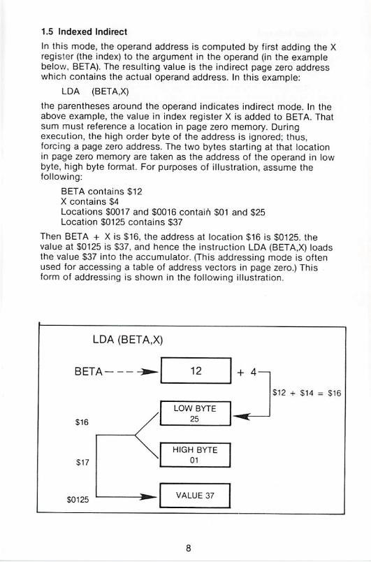
1,5 Indexed Indirect
In this mode, the operand address is computed by first adding the X
register (the index) to the argument in the operand (tn the example
below, BETA). The resulting value is the indirect page zero address
which contains the actual operand address. In this example:
LDA (BETATX)
the parentheses around the operand indicates indirect mode. In the
above example, the value in index register X is added to BETA. That
sum must reference a location in page zero memory. During
execution, the high order byte of the address is ignored: thus,
forcing a page zero address. The two bytes starting at that location
in page zero memory are taken as the address of the operand in low
byte, high byte format. For purposes of illustration, assume the
following:
BETA contains $12
X contains $4
Locations $0017 and $0016 contain $01 and S25
Location $0125 contains $37
Then BETA + X is $16. the address at location 516 is S0125. the
value at $0125 is $37. and hence the instruction LDA (8ETA.X) loads
the value $37 into the accumulator. (This addressing mode is often
used for accessing a table of address vectors in page zero.) This
form of addressing is shown in the following illustration.
LDA (BETA,X
BETA ^-
$16
S17
S0125
/\
)
12 + 4—
LOW BYTE
25
HUGH BYTE
01
VALUE 37
S12 + $14 = $16
^*

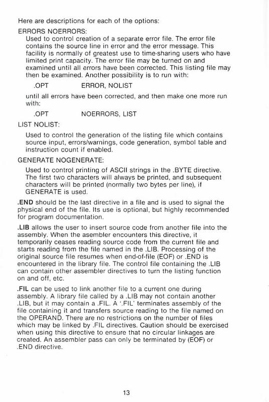
1.6 Indirect Indexed
Another mode of indirect addressing uses index register Y and is
illustrated by:
LDA (GAMMA),Y
In this case. GAMMA references a page zero location at which an
address is to be found. The value in index Y is added to that
address to compute the actual address of the operand. Suppose for
example that.
GAMMA contains $38
Y contains S7
Locations SQ039 and $0038 contain $00 and S54
Location S005B contains $126
The address at S38 is $0054; seven is then added to this, giving an
effective address S005B. The value at S005B is $126 which is loaded
into the accumulator.
In indexed indirect, the index X is added to the operand prior to the
indirection. In indirect indexed, the indirection is done and then the
index Y is added to compute the effective address. Indirect mode is
always indexed except for a JMP instruction which allows a
absolute indirect address, as exemplified by JMP (DELTA) which
causes a branch to the address contained in locations DELTA and
DELTA + 1. The indirect indexed mode of addressing is shown in the
following illustration.
LDA (GAMMA).Y
GAMMA -*
S38
38
54
$39
S005B
00
VALUE 126
50054 + $7 = S5B

2.0 ASSEMBLER DIRECTIVES
There are eleven assembler directives used to reserve storage and
direct information to the assembler. Nine have symbolic names with
a period as the first character. The tenth, a symbolic equate, uses
an equals sign ( = ) to establish a value for a symbol- The eleventh,
asterisk. (') means Ihe value of the current location counter. This
corresponds to the ORG directive in some assemblers. It is
sometimes read as "here" or "this location". Some equate examples
are "RED-5. BLUE = SFF. and * = $200". A list of the directives is
given below (their use is explained in this section):
.BYTE .WORD .DBYTE .PAGE .SKIP
.OPT END .FILE .LIB
Labels and symbols other than directives may not begin with a
period.
Examples of assembler directives can be seen in the sample
Assembler program in Appendix V.
If desired, all directives which are preceded by the period may be
abbreviated to the period and three characters, e.g., '.BYT.
.BYTE is used to reserve one byte of memory and load it with a
value. The directive may contain multiple operands which will store
values in consecutive bytes. ASCII strings may be generated by
enclosing the string with quotes. (All quotes are "single" quotes, i.e,
SHIFT 7.) It should be noted, however, that there is a limitation of 40
ASCII characters that can be stored in each .BYTE directive.
HERE .BYTE 2
THERE .BYTE 1, $F, @3, %101, 7
ASCII .BYTE 'ABCDEFH'
Note that numbers may be represented in the most convenient form.
In general, any valid 6500 series expression which can be resolved
to eight bits, may be used in this directive. If it is desired to include
a quote in an ASCII string, insert two quotes in the string. For
example:
BYTE 'JIM"S CYCLE1
could be used to store:
JIM'S CYCLE
It should be noted that the use of arithmetic operations in the .BYTE
directive is not supported in this version of the package.
10

.WORD is used to reserve and load two bytes of data at a time Any
valid expression, except for ASCII strings, may be used in the
operand field. For example;
HERE .WORD 2
THERE .WORD 1, SFF03. @3
WHERE .WORD HERE, THERE
The most common use for WORD is to generate addresses as
shown in the previous example labelled "WHERE", which stores the
16 bit addresses ot -HERE11 and "THERE'. Addresses in the 6500
series are fetched from memory in the order low-byte, then htgh-
byte. Therefore. .WORD generates the value in this order.
The hexadecimal portion of the example (SFF03) would be stored
Q3tFF. if this order is not desired, use .DBYTE rather than ,WORD.
.DBTYE is exactly like .WORD, except the bytes are stored in high-
byte, low-byte order. For example:
.DBYTE $FF03
will generate FF,03. Thus, fields generated by .DBYTE may not be
used as indirect addresses.
Equal ( = ) is the EQUATE directive and is used to reserve memory
locations, reset the program counter O, or assign a value to a
symbol.
reserve one byte
reserve two bytes
set program counter
assign value
assign value
the '= " directive is very powerful and can be used for a wide variety
of purposes.
Asterisk (') directive is used to change the program counter. To
create an object code program that starts assembly at any address
greater than zero, the '•' directive must be used. For example.
" - S2001. starts assembling at address $200.
Expressions must not contain forward references or they will be
flagged as an error. For example:
- = C+D-E+F
wouid be legal if C. D. E and F are all defined, but would be illegal if
any of the variables were defined later on in the program. Note also
that expressions are evaluated in strict left to right order.
HERE
WHERE
4 = $200
NB = 8
MB=NB+5Q
*
101
■ +
* +
1
2
11

.PAGE is used to cause an immediate jump to top of page on the
output listing and may also be used to generate or reset the title
printed at the top of the output listing.
PAGE 'THIS IS A TITLE'
PAGE
PAGE 'NEW TITLE'
If a title is defined, it-will be printed at the top of each page until it
is redefined or cleared. A title may be cleared with:
.PAGE ' '
.SKIP is used to generate blank lines in a listing. The directive will
not appear, but its position may be found in a listing. The directive
is treated as a valid input "list" and the list number printed on the
left side of the listing will jump by two when the next line is printed.
.SKIP 2 skip two blank lines
.SKIP 3*2-1 skip five lines
SKIP skip one line
.OPT is the most powerful directive and is used to control the
generation of output fields, listings and expansion of ASCII strings
in BYTE directives. The options available are: ERRORS,
NOERRORS; LIST, NOLIST; GENERATE, NOGENERATE.
.OPT ERRORS, LIST. GENERATE
.OPT NOE, NOL, NOG
Also valid is:
OPT LIST. ERR
Default settings are:
.OPT LIST, ERR, NOGEN
12
Here are descriptions tor each of the options:
ERRORS NOERRORS:
Used to control creation ot a separate error file. The error tiie
contains the source line in error and the error message. This
facility is normally of greatest use to time sharing users who have
limited print capacity. The error file may be turned on and
examined until all errors have been corrected. This listing file may
then be examined. Another possibility is to run with:
.OPT ERROR, NOLIST
until all errors have been corrected, and then make one more run
with:
,OPT NOERRORS. LIST
LIST NOLIST:
Used to control the generation of the listing file which contains
source input, errors/warnings, code generation, symbol table and
instruction count if enabled.
GENERATE NOGENERATE:
Used to control printing of ASCII Strings in the .BYTE directive.
The first two characters will always be printed, and subsequent
characters will be printed (normally two bytes per line), if
GENERATE is used.
.END should be the last directive in a file and is used to signal the
physical end of the file. Its use is optional, but highly recommended
for program documentation.
.LIB allows the user to insert source code from another file into the
assembly. When the asembler encounters this directive, it
temporarily ceases reading source code from the current fi!e and
starts reading irom the file named in the .LIB. Processing of the
original source file resumes when end-of-file (EOF) or .END is
encountered in the library file. The control file containing the .LIB
can contain other assembler directives to turn the listing function
on and off. etc.
.FIL can be used to link another file to a current one during
assembly. A library file called by a .LIB may not contain another
.LJB. but it may contain a .FIL, A l_FIL' terminates assembly of the
file containing it and transfers source reading to the file named on
the OPERAND. There are no restrictions on the number of files
which may be linked by .FIL directives. Caution should be exercised
when using this directive to ensure that no circular linkages are
created. An assembler pass can only be terminated by (EOF) or
.END directive.
13

3.0 MACRO CAPABILITIES
Macros take the general form shown in the following code:
{label) .MAC macro name
TEXT OF MACRO
(label),MND
The directive .MAC defines a macro with the given macro name and
creates up to nine parameters for that macro. The user does not
explicitly declare parameters. Macros may contain arbitrary text,
except that they cannot contain the directives .MAC and .MND. The
directive .MND identifies the end of a macro definition. The labels
on .MAC and .MND are optional as denoted by the parenthesis. They
respectively label the first generated statement and the statement
immediately succeeding the last generated statement.
To call a macro, the user simply gives the marco name and lists the
parameters as indicated in the cali line below:
macroname parami, param2,
The macro name must be delimited by a space before the first
parameter as indicated above.
Within the text of the macro definition, a parameter is designated by
the temporary symbol ll?1T followed by a digit 1 through 9. Thus, l?3'
designates parameter 3. During assembly, if a macro call is
encountered, the text included in that macro is inserted into the
assembly at that point and the parameter names at the calling point
are substituted for the temporary names. If the user fails to supply a
parameter name when the macro is called, the assembler will
generate a name for that parameter (if one is needed) for the
duration of that call.
To give a brief example, suppose we wish to increment a double
precision (16-bit) quantity. Then, the macro definition to do this is:
.MAC DPINC ;DOUBLE PRECISION INCREMENT
INC ?1
BNE ?2
INC ?1 + 1
?2 .MND
When the macro is called to increment the variable COUNT, the
following call line is used.
DPINC COUNT
This generates the following code:
INC COUNT
BNE L001
INC COUNT+1
LO01
14

In this example, the internal label name ''LOOl11. is generated
automatically during macro expansion. Subsequent calls produce
distinct labels following the progression L002. L003. etc, If the
programmer supplies a second parameter ?n the calling line, instead
of leaving that parameter blank, the internal label name will be set
to the second parameter instead of L001.
Macro can call other macros, but the depth of the nesting cannot
exceed eight levels.
Empty Parameters
Empty parameters in call lines are denoted by commas:
FUNCTN AA,.,DO PARAMETERS ?2 AND ?3 ARE
EMPTY AS ARE: ?5 THROUGH ?9
FUNCTN ,.CC,.EE :?1, ?2. AND ?4 ARE EMPTY AS ARE
?6; THROUGH ^9
The calls on FUNCTN given here will result in different internal local
parameters being given generated names, or names supplied from
the programmer.
Concatenated Names
A macro parameter is supplied to a macro without leading or trailing
blanks, so that a parameter can be used to create new variable
names and allocate space for the variables.
DECLARED STORAGE
THIS IS A MACRO CALL
:THIS IS HOW IT EXPANDS
fTHIS IS A SECOND CALL
[THIS IS HOW THE SECOND CALL
EXPANDS
Notice that there are no blanks in the labels XXAA and XXA2.
XX? 1
XXAA
XXA2
.MAC
AA/OR
* = * +
.MND
DECL
WOR
' = " +
DECL
.WOR
* = * +
?2
5
10
DECL
0
AA.5
0
A2,10
15

Expressions As Parameters
Parameters of macros can be arbitrary expressions that do not
include embedded commas, semicolons, or blanks. When the
expressions are inserted into the macro definition, the expression
must make sense to the assembler.
MAC LSS ;IF ACCUM LESS THAN ?1 GOTO ?2
CMP ?1
BCS ?2
-MND
LSS XX + 5.EXIT ;COMPARE WITH LOCATION XX + 5
LSS #SF3,EXIT ;COMPARE WITH LITERAL
LSS (XX.UEXIT ILLEGAL—AN EMBEDDED COMMA
Assembler Output Format
Note: The macro assembler uses different rules than the previous
Commodore assembler in deciding how to format a print line. The
new rule is the following:
An identifier that begins in column 1 is printed as a label,
otherwise it is assumed to be an opcode.
This rule is identical to the rule used by the editor for the FORMAT
command. Hence, the FORMAT command now permits the user to
view the final printed format of edited files.
16

4.0 OUTPUT FILES GENERATED BY THE ASSEMBLER
There are three output files generated by the assembler. Each file is
optional and can be created through the use of the .OPT assembler
directive. The listing file contains the program list with errors and
the symbol table. The error file contains all error lines and errors (as
included in the listing file}. The interface file contains the object
code for the loader.
The cross reference file may optionally be generated by the
assembler. This file is used by the cross reference program to print
a report showing all variables, their declared addresses, and ail line
numbers in which each variable is used.
Listing File
The listing file will be produced unless the NOLIST option is used
on the .OPT assembler directive. This file is made up of two
sections: Program and Error List, and Symbol Table.
• Program and Error List
This listing will always be produced unless the NOLIST option is
selected. It contains the source statement of the program along
with the assembled code. Errors and warnings appear after
erroneous statements, (An explanation of error codes is presented in
Appendix VI.) A count of the errors and warnings found during the
assembly is presented at the end of the parogranv
• Symbol Table
The symbol take will always be produced unless the NOSYM option
is used. It contains a list of all symbols used in the program, and
their addresses.
17

Interface File
This file does not contain true object code, but data which can be
loaded and converted to machine code by the loader. The format for
the first and all succeeding records, except for the last record, is as
follows:
; n1nO a3a2a1aO (d1dO)1 (d1dO)2...(d1dO)23 x3x2x1xO
Where the following statements apply:
1. All characters (n,a,d,x) are the ASCII characters zero through F,
each representing a hexadecimal digit.
2. The semicolon is a record mark indicating the start of a record.
3. n1nO The number of bytes of data in this record (in
hexadecimal). Each pair of hexadecimal characters
(d1dO) represents a single byte.
4. a3a2a1aO The hexadecimal starting address for the record.
The a3 represents address bits 15 thru 12, etc. The
8-bit represented by (d1dO)1 is stored in address
a3a2a1aO: (d1dO}2 is stored in (a3a2a1aO)+ 1, etc.
5. (d1dO) Two hexadecimal digits representing an 8-bit byte
of data. (d1 = high-order 4 binary bits and dO -
low-order 4-bis). A maximum of 18 (Hex) or 24
(decimal) bytes of data per record is permitted.
6. x3x2x1xO Record check sum. This is the hexadecmial sum ofall characters in the record, including the n1nO and
a3a2a1aO, but excluding the record mark and the
check sum of characters. To generate the check
sum, each byte of data (represented by two ASCII
characters) is treated as 8 binary bits. The binary
sum of these 8-bit bytes is truncated to 16 binary
bits (4 hexadecimal digits) and is then represented
in the record as four ASCII characters (x3x2x1xO).
The format for the last record in a file is as follows:
; 00 c3c2dcO x3x2x1x0
1. ; 00 Zero bytes of data are in this record. The zeros
identify this as the final record in a file.
2. c3c2dcO This represents the total number of records (in
hexadecimal) in this file. NOT including the last
record.
3. x3x2xlxO Check sum for this record.

5.0 ADDITIONAL BASIC DISK COMMANDS (DOS SUPPORT
WEDGE)
On the release disk is a program which will aid you in performing
disk housekeeping functions (copying, scratching, renaming, reading
the directory, initializing the disk drive, checking the disk status, and
loading (and running) programs from disk. The commands that this
program provides are short and simple and are very usetul.
5.1 Loading the DOS WEDGE64 Program
When this program is loaded and executed, it "wedges" itself into
the operating system and BASIC interpreter. Thus, the wedge
checks all keyboard entries for its command characters before
passing the entry onto the BASIC interpreter. (This is done by
linking into the CHRGET routine in page zero).
To load the wedge program, enter:
LOAD "DOS WEDGE64".8,1
and press RETURN. This will load a program that "boots" the actual
wedge program into memory. Once loaded, type RUN and press
RETURN before removing the diskette. When the wedge program is
loaded, a copyright notice will be displayed.
5.2 Using the DOS WEDGE64 Program
The wedge program supports all of the same commands that are
included in BASIC (copy, scratch, rename, new a disk), a command
to read the directory (without overwriting memory), and commands
to load and run programs. The wedge program also provides you
with the capability of creating and maintaining volumes of files
(volumne creation allows you to group certain programs together)
and the capability to perform operations using a wild card filename
(and file whose name begins with certain charactersj.
Each command begins with a single character as specified in
Section 5.3. The character used depends on the command. The @
(commercial at sign) and > (greater than sign) are used
interchangeably to begin any of the disk housekeeping commands
or to read the directory. They are also used to reset or initialize the
drive, and to terminate the DOS Wedge. The t (up arrow) is used to
begin the command to load (at BASIC'S Start of Text address) and
automatically runs a program. The / (backslash) is used to begin
the command to load a program at BASIC'S Stan of Text address.
The % (percent sign) is used to begin the command to load a
program at its load address. Finally, the *■ (back arrow) is used to
begin the command for saving a file to disk.
19

5.3 DOS WEDGE64 Program Commands
A description of each command is given in the following pages.
Appendix IX provides a brief summary of the DOS WEDGE64
commands.
■a
Typing this character alone will provide the user with the current
disk status. This performs the same function as the following BASIC
code:
10 OPEN 15,8.15
20 INPUT#15,A.B$,C.D
30 PRINT A:BS;C;D
./r${drive}:(filename)n([volume]|
This command will read the directory from the disk drive specified
and print il to the screen. If filename is specified, only that file, if
present, will be displayed. If ' is specified, all files whose names
begin with the letters specified by filename will be printed. If
volumn is specified (where volume is the character id of that
volume}, then only those files contained on that volume will be
printed.
@ N(drive):diskname,id
This command will format a disk using the name and id specified.
m R(drive):newfile([volume]) = oldfile([volume])
This command will rename the file specified by oldfile to the name
specified by newfile.
^C(drive):newfile([volume]) = oldfile([volume])
This command will copy the file specified by oldfile to the name
specified by newfile. If [volume] is specified, the newfile will be
created on that volume.
■n S(drive):1ilenarnen<[volume])
This command scratches the file specified by filename. If * is
specified, all files beginning with the letters specified by filename
will be scratched. If [volume] is specified, only those files that are
contained on that volume will be scratched.
^Ul (drive}
This command will reset the DOS.
•;1 (drive)
This command will initialize the disk drive.
@Q
This command will terminate the wedge program.
20
/filename
This command will load the file specified by filename. For example:
/ASM.C64
will cause the program named "ASM.C64" to be loaded into
memory. This command does the same thing as the BASICcommand:
LOAD "ASM.C64",8
Please note that this command can only be used to load BASIC
programs, or machine code programs that are booted from BASIC.
This is because the computer will ignore the file's own load address
and will instead load at the current "Start of BASIC Text" area.
%filename
This command will load the file specified by filename at its own
load address. It does the same thing as the BASIC command:
LOAD *lfilename".8,1
where filename is the name of the program to load,
t filename
This command allows the user to load and run the program
specified by filename and does the same tiling as entering:
LOAD "filename",8
follows by the BASIC command RUN.
Again, please note that this command can only be used to load and
run BASIC programs, or machine code programs that are bootedfrom BASIC.
— filename
This command saves the program specified by filename to disk.

6.0 CREATING AND EDITING A SOURCE FILE
The editor is used to enter and modify source files for the
assembler. The editor retains all of the features of the BASIC screen
editor and allows AUTOmatic Sine numbering, FIND, CHANGE,
DELETE within a range, and reNUMBER. Other commands include
GET, PUT, BREAK, KILL, and FORMAT. All of the commands are
detailed in the summary at the end of this section.
The editor commands operate in a similar fashion to the commands
already existing in the computers BASIC. For practice, we suggest
that you try to create short example files using the editor
commands.
The data files on which the assembler operates are made up of
CBM ASCII characters with each line terminated by a carriage
return. The only restriction on data files is in naming. Due to the
method in which the assembler parses, spaces are not allowed in
filenames. The files are sequential and must be terminated by a zero
byte $00. When listing a directory, these files will show as file type
SEQ.
Each file's format is sequential, with a terminating zero byte ($00),
22

6.1 Loading the Editon34 Program
The editor must be loaded with the Basic LOAD command:
LOAD "EDITOR64'\8.1
or %0;EDITOR64 (if the wedge is enabled)
To initiate the editor, type •SYS49152". After typing the SYS
command, the editor will respond with a message indicating that
the 64 editor has been loaded. At this potnt, type a NEW command
to clear the text pointers. You are now ready to edit or enter
assembler source files.
6.2 Using the Editor64 Program
When the Editor64 Program is in operation, any BASIC statement
typed such as:
10 FOR 1 = 1 TO 10
will not be tokenized (converted into BASIC keyword tokens). Thus,
you cannot type a BASIC line with the editor turned on. To avoid
this problem, disable the editor with the 'KILL' command or reset
the computer to return to Basic.
Source files are loaded with the "GET" command. As the file is
loaded, the editor generates the line numbers automatically starting
at 1000. After editing the file, insure that the last, line in the file is a
.FILE or a .END assembler directive. Then, save the file on the disk
with the 'PUT' command.
Important: Be sure to save your completed file using the PUT
command BEFORE loading the assembler or your file will be last.
Refer to Appendix V!l for an Editor64 Command Summary.
23

6.3 Editor64 Program Commands
AUTO Line Numbering
The AUTO command generates new line numbers while entering a
new source code file. To enable the AUTO command] type the
following:
AUTO n1
where n1 is the optional increment between line numbers printed.
To disable the AUTO function, type the AUTO command without an
increment.
CHANGE string
The CHANGE command automatically locates and replaces one
string with another (multiple occurrences). This command is entered
in the following format:
CHANGE/stM/str2/ ,n1-n2
\ Delimits the str1 and str2 (use any character not in
either string)
siri Search string
str2 Replacement string
tn1-n2 Range parameters. The format is the same as the
LIST command in BASIC. If omitted, the whole file
is searched. (Optional)
CPUT Command
The CPUT command outputs source files with no unnecessary
spaces to the disk for later assembly. The syntax for this command
is the same as the PUT command.
DELETE
The DELETE function allows the user to delete several lines at a
time. Simply input the range of lines to be deleted (n1 through n2).
(The format is the same as the LIST command in BASIC).
DELETE n1-n2
To delete a single line, enter the line number alone on a blank line
and press RETURN.
24

FIND String
The FIND command is used to search lor and locate specific
character strings in text. Each occurrence of the string is printed on
the CRT. You can pause the printing with the space bar. Printing
can then be continued with the space barF or terminated with the
RUN/STOP key. The format of the FIND command is;
FIND/str1/ ,(n1 n2)
/ Delimiter (use a character not in the string)
stn Search string
,n1-n2 Range parameter. Same as the LIST command in
BASIC (Optional)
FORMATted Print
The FORMAT command is used to print the text file in tabbed
format like the assembler. For this function to work correctly, you
must type mnemonics in column two, or one space from labels.
FORMAT (n1-n2)
n1-n2 Range parameters of the same (ormat as LIST,
(Optional).
Note: ThJs command has the same controls as FIND. For example,
press space bar to halt printing and another space bar to restart
printing. Press the RUN/STOP key to terminate the program.
GET Files
This command is used to load assembler source text files into the
editor from disk. It can also be used to append to files already in
memory.
GET -filename" ,(ni)((n2)H(n3}
n1 Begins inputting source at this line in the file
currently in memory (Optional)
n2 Device number, default is 8 (Optional)
n3 Secondary address default is 8 (Optional)
Note: GET starts numbering lines at 1000 and incrementing the line
numbers by 10. If n1 is greater than any line number in memory, the
file being loaded is appended to the end of the current file.
25

KILL Command
This command causes the editor to disengage. To restart the editor,
type the same command used to start the editor (SYS49152).
LIST Command
The editor LIST command works in the same manner as the LIST
command jn BASIC,
LIST(n1}-(n2)
where ni-n2 specifies a range of lines. Valid parameters also include
'n1-' (which will list all lines from n1 to the end) and "-n2' (which will
list all lines from the beginning up to and including n2).
ReNUMBER Lines
The NUMBER function alllows the user to renumber all or part of
the file in memory.
NUMBER (n1).(n2),{n3)
n1 Old start line number (Optional)
n2 New start line number {Optional)
n3 Step size for resequence (Optional)
PUT Command
The PUT command outputs source files to the disk for later
assembly. PUT has the ability to output all or part of the memory
resident file.
PUT "filename" .(n1-n2),{n3Mn4)
n1 Starting line number (Optional)
n2 Ending line number (Optional)
n3 Device number, default is 8 (Optional)
n4 Secondary address, default is 8 (Optional)
If n1-n2,n3,n4 are left out, the whole file is output to the disk.
26

7.0 ASSEMBLING A SOURCE FILE
Once a source file is ready to assemble, you must first save it ondisk (by using the PUT command). Please be sure to do this before
loading the assembler program. Once this is completed, you will
load the assembler which will reside in the same area that BASICprograms do.
7.1 Loading the Assembler64 Program
To load the assembler, type:
LOAD "ASSEMBLER64",8 (or /ASSEMBLER64 if the DOS
Wedge is loaded)
After loading is complete, type RUN and press RETURN. The
assembler will print a copyright notice and the first user prompt
when execution begins.
27

7.2 Using the Assembler64 Program
When a program is being assembled, the user has the option of
creating two types of files. The first type is an object file whichcontains the data necessary to create a machine code program (by
the loader). The name of this file is specified by the user beforeassembly starts. The remaining files are cross reference files. The
names for these files are automatically generated by the assembler
and are in the format ilXXLLOOO0" and "XXFF0000".
It should be noted however, that the assembler program will not
overwrite any of these files. If you wish to use the same objectfilename each time you assemble a program, you must -scratch"
the old object file before you run the assembler. In the case of
cross reference files, the same procedure should be followed if you
want to create new cross reference files.
Although you will be given the option of creating both an object fileand cross reference files before assembly starts, only one of these
options can be chosen (because of the number of files open at one
time). If you want both files, run the assembly once with the object
file option, and once with the cross reference option.
When the assembler starts, the first prompt will be:
OBJECT FILE (CR OR D:NAME):
If you want the assembler to create an object file enter the filename
and press RETURN. If not, press RETURN.
Next you will be prompted with:
HARD COPY (CR/Y OR N)?
if you want a hardcopy printout, enter Y and press RETURN orsimply press RETURN. If not, enter N and press RETURN. This will
cause the output to be listed to the screen.
Next, you will be prompted with:
CROSS REFERENCE (CR/NO OR Y)?
If you want a cross reference file created, enter Y and press
RETURN. If not, simply press RETURN.
Finally, you will be prompted with:
SOURCE FILE NAME?
Enter the name of the source file that you wish to assemble.
After entering this last prompt, the assembler program begins to
execute. If during assembly, the symbol table overflows, the
assembly process will stop.
28
HALTING THE ASSEMBLER
When the assembler is running, operation may be halted by
pressing the RUN/STOP key. ff this is done, the assembly process
will be stopped and the program will wait for the user to either
continue the assembly or to terminate it completely. Press the B key
to terminate the assembly and return to BASIC. Pressing any other
key will continue the assembly process. This feature is useful for
users without printers, as the screen listing can be examined duringassembly.
CROSS REFERENCE FILES
If you chose to create a cross reference, two files will be created as
was mentioned above. To look at or produce a hardcopy printout of
this cross reference, you must first load the cross reference listing
program. To load this program, type:
LOAD "CROSSREF 64",8
Once this program is loaded, type RUN and press RETURN and the
cross reference listing program will prompt with:
HARD COPY (CR/Y OR N)?
Press RETURN if you want a hardcopy printout; otherwise, enter N
and press RETURN.
29

8.0 LOADING AN OBJECT FILE
The Commodore 64 Assembler produces portable output in an ASCII
format that can not be directly executed- This output must be
LOADED so the program can be executed. This is the function of a
Loader.
8.1 Loading the Loader Program
There are two versions of the loader included on the development
disk. Each version is positioned in a different area of RAM memory.
This allows the user to load anywhere in RAM by using the correct
loader. To load one of the Loader programs, type:
LOAD"filename",8r1
where filename is the program to be loaded. The following table
shows the names, load points and run commands for each loader.
Name Load Address Run Command
LO-LOAD.C64 $0800 RUN
HI-LOAD.C64 SC800 SYS 51200
30

8.2 Using the Loader Programs
Both the HI-LOAD and LO-LOAD loaders are about 512 bytes long
and operate in the same manner. When activated, the loaders print a
copyright notice and prompt the user fora load offset. The offset is
used to place object code into an address range other than the one
that it was assembled into. This allows the user to assemble for an
area where there is no RAM and load into a RAM area. The object
can then be programmed into EPROM etc..
The offset is a two byte hexadecimal address that is added to the
program addresses. If the program address plus the offset is greater
than SFFFF, the address wraps around through $0000. The following
examples show how offset works.
Address of Object CodeProgram Address
S0400
S3000
$0400
$9000
SE000
Offset
soooo
soooo
$2000
S9000
$4000
Addre
S0400
$3000
52400
$2000
$2000
After the offset is entered, the loader will prompt the user for the
object filename to be loaded. The loader will then initialize the drive,
search for the file, and start the load. As the data is loaded, the
program will print the input data to the CRT. This is for user
feedback only. When the load is completed, the loader prints the
message bEND OF LOAD1 and returns to BASIC.
There are three errors that can occur during a load {each is self
documenting):
BAD RECORD COUNT
NON-RAM LOAD
CHECKSUM ERROR
Errors are considered fatal; the load is terminated, the object file
is closed, and control is returned to BASIC.
31

9.0 TESTING AND DEBUGGING WITH THE MONITOR PROGRAMS
The MONITOR is the machine language monitor for the Commodore
64. This programming aid contains many features that will enable
you to create, modify and test machine language programs and
subroutines. The MONITOR'S purpose is to make it easy for you to
examine and change memory while debugging your program.
9.1 Loading the MONITOR Programs
There are two machine language monitors on the Commodore 64
Assembler Development disk: MONITOR$8000 and MONITOR$C000.The only difference is the area of memory in which the program
resides. MONITORS8000 resides at memory location $8000 and
MONITORSC000 resides at memory location SC000. The two
MONITOR programs are both included in case one interferes with
the intended location lor the machine code program to reside.
To load and activate the appropriate monitor, enter:
LOAD "MONITOR$8000",8,1 (monitor at $8000)
SYS 32768
or
LOAD ■■MONITOR$C000",8,1 (monitor at SC000)SYS 49152
9.2 Using the MONITOR Programs
The MONITOR programs will respond by displaying the CPUregisters, typing a period, and flashing the cursor. The period is a
prompt that lets you know the MONITOR program is waiting for your
command. The commands are described on the following pages.Appendix VIII provides a summary of MONITOR commands.
To exit the MONITOR program, reset the machine.

9.3 MONITOR Program Commands
COMMAND: A
Purpose: Enter a line of assembly code.
Syntax: A(address)(opcode mnemonic)(operand)
(address): A four-digit hexadecimal number indicating the location in
memory to place the opcode.
{opcode mnemonic): A standard MOS assembly language
mnemonic, i.e. LDA, STX, ROR, etc. as defined in Appendix IV.
(operand): The operand, when required, can be of any of the legal
addressing modes. (For zero-page modes, a two digit hex number is
required whose value is less than or equal to $FF. For non-zero page
addresses, a four digit hex number whose value is less than or
equal to SFFFF is required.)
A RETURN is used to indicate the end of the assembly line. If there
are any errors on the line, a question mark is displayed to indicate
an error, and a period is typed on the next line. The screen editor
can be used to correct any errors on the original line.
After a line of code is successfully assembled, the assembler will
print a prompt containing the next legal memory location for an
instruction, so 'A' and the line number do not have to be typed more
than once when typing assembly language programs into the
Commodore 64. To exit this mode, press RETURN after the 'A'
prompt.
Example: .A1200 LDX #$00
.A 1202
COMMAND: C (COMPARE)
Purpose: Compare two areas of memory
Syntax: C(start address)(end address)(with address)
(Start Address): A four digit hex number indicating the start address
of the area of memory to compare against.
(End Address): A four digit hex number indicating the end address
of the area of memory to compare against.
(With Address): A four digit hex number indicating the start
addresss of the other area of memory to compare with.
The address fields should be separated by a valid delimiter, such as
a space or comma. If the two areas of memory are the same, then
64MON will print a period, indicating that the second area of
memory is the same as the first. The addresses, of any bytes in the
two areas which are different, are printed out on the screen in
descending order.
33

COMMAND: D (DISASSEMBLE)
Purpose: Disassemble machine code into assembly language
mnemonics and operands.
Syntax; D(address 1}(address 2)
(address 1): A four-digit hexadecimal starting address of the code to
be disassembled.
(address 2): An optional four-digit hexadecimal ending address of
the code to be disassembled.
The address fields should be separated by a delimiter such as a
space or comma. The format of the disassembly is only slightly
different than the input format of an assembly. The difference is that
the first character of a disassembly is a comma, rather than an 'A'
(for readability).
A disassembly listing can be modified using the screen editor. Make
any changes to the mnemonic or operand on the screen, then press
RETURN. This will enter the line and call the assembler for further
modifications.
A disassembly can be scrolled up or down on the screen via cursor
control. When a line of disassembly is at the bottom of the screen,
a cursor down will cause the screen to scroll up one line to display
another disassembled line of code. This also works for scrolling
backwards through a disassembly (i.e.T going to the top of the
screen and hitting cursor up).
Example: D 1000 1400
., 1000 LDA #$00
., 1002 ???
., 1003 BNE Sf1030
COMMAND: F (FILL)
Purpose: Fill a range of locations with a specified byte.
Syntax: Fladdress 1)(address 2)(byte)
(address 1): The first location to fill with the value specified by (byte)
(address 2): The last location to fill with the value specified by (byte)
(byte): A two digit hexadecimal number to be written into
consecutive memory locations
This command is useful for initializing data structures or any other
RAM area.
Example: F 0400 0518 EA
Fills memory locations from $0400 to $0518 with SEA (a NOP
instruction,)
34
COMMAND: G (GO)
Purpose: Begin execution of a program at a specified address.
Syntax: G(address}
(address): An optional argument specifying the new value of the
program counter and address where execution is to start. When the
address is left out, execution wili begin at the current PC. (The
current PC can be viewed using the R command.)
The GO command will restore all registers (displayabie by the R
command) and begin execution at the specified starting address.
Caution is recommended in using the GO command. (It may
sometimes be wise to set a breakpoint somewhere in the line of
program execution to prevent loss of control of the operating
system.)
Example: G 040C
Execution begins at location 040C.
COMMAND: H (HUNT)
Purpose: Hunt through memory within a specified range for all
occurrences of a set of bytes.
Syntax; H(address 1)(address 2)(data)
(address 1): Beginning address of hunt procedure
(address 2): Ending address of hunt procedure
(data): Data set to be searched (data may be hexadecimal or an
ASCII string)
An ASCII is specified by preceding the first character with a single
quote, i.e., 'STRING. Data may be single or multiple arguments.
Multiple two-digit hex arguments must be separated by a space
Example: H C000 FFFF 'READ ; Search for ASCII string READ
H A000 A101 A9 FF 4C; Search for data $A9, $FF, $4C.
in tnat sequence
35

COMMAND: I (INTERROGATE)
Purpose: Display memory in ASCII character format within the
specified address range.
Syntax: 1(address1)(address 2)
(address 1): Starting address of ASCII dump
(address 2): Ending address of ASCII dump
The ASCII characters are displayed in reverse video (to contrast the
character with the hexadecimal data displayed on the screen),
The display can be made to scroll by using the cursor up/down key.
This allows continuing the search beyond the search parameters.
When a line of the listing is at the bottom of the screen, a cursor
down will cause the screen to scroll up one line to display another
line of the listing. This also works for scrolling backwards (i.e.,
going to the top Of the screen and typing cursor up).
Note: When a character is not printable, it will be displayed as a
period (.).
Example: 1 C000 C020
Dispiays in REVERSE all data from SCOOO to SC020,
COMMAND: L (LOAD)
Purpose: Load a file from cassette or disk.
Syntax: L "filename".(device)
filename: Any legal Commodore 6^ filename
(device): A two-digit byte indicating the device number from which
to load
01 is cassette
08 is disk (or 09. etc.)
The LOAD command causes a file to be loaded into memory. The
starting address is contained in the first two bytes of the file (in a
PGM file), in other words, the LOAD command always loads a file
into the same pJace it was saved from. This is very important in
machine language work, since few programs are completely
relocatable. The file will be loaded into memory until the end of fite
marker (EOF) is found.
Example: L "SCREEN". 01 :reads a file from cassette
L 'TANK".O8 :reads a file from disk drive
36

COMMAND: M (MEMORY DISPLAY)
Purpose: To display memory as a hexadecimal dump within the
specified address range-
Syntax; M(address i)(address 2)
(address 1): First address of hex dump
(address 2): Last address of hex dump (Optional. If omitted, eight
bytes will be displayed.)
Memory is displayed in the following format:
.:AO48 7F E7 00 AA AA AE 02 FF
Memory content may be edited using the screen editor. To edit,
move the cursor to the data to be modified. Type the desired
correction and press RETURN. If there is a bad RAM location or if
an attempt to modify ROM has occurred, an error flag (?) will be
displayed.
As with the DISASSEMBLY and INTERROGATE commands, the
screen may be scrolled both up and down by using the cursor
controls.
Example: M 0000
.:0000 4C 7F EF AA 00 02 F7 FF
The first eight bytes of memory are displayed.
37

COMMAND: N (NEW LOCATOR)
Purpose: To relocate absolute memory references by adding an
offset to the operands of the target code.
Syntax: N{address i)(address 2)(offset)(ref 1)<ref 2)W
(address 1): Starting address of code to be modified
(address 2): Ending address of code to be modified
(offset): Value to be added to operand of instructions
Code moved from a high location to a low location in memory needs
a value which wraps around. For example, a piece of code moved
from SAOOO to $0400 will require an offset of $6400.
£A000 + $6400 = 310400, but since there is not a bit nine in the
computer, the result is $0400.
{ref 1): Any three byte instruction whose operand is greater than or
equal to {ref 1) and less than (ref 2} will be offset by the (offset)
value, i.e., the operand of the three byte instruction will be replaced
by 'operand + (offset)'.
(ref 2): Upper timit of operands to relocate (see ref 1). Any operand
with a value greater than or equal to (ret 2) will not be relocated.
W; Relocate word tables, (optional). Every two bytes will be offset if
the W is included. Relocation then becomes data independent.
Often it is useful to move a section of code from one area in
memory to another (see the "I11 command) to make room for more
code. Then by using the "N" command, the code can be changed to
run in the new address space.
COMMAND: R (REGISTER DISPLAY}
Purpose: Show important 6502 registers. The program status
register, program counter, the accumulator, the X and Y index
registers and the stack pointer are displayed.
Syntax: R
Note that the stack pointer is displayed without its implied eighth
bit. Since the eighth bit of the stack pointer has been mentioned, it
is appropriate to point out a bug in the 6502. When a PHP
instruction is executed, the stack eighth bit of the stack pointer is
ORe'd into the status byte and is stored on the stack with bit four
(the break flag!) always set. For 99.9% of atl applications, this
makes no difference. However, when this bug does turn up. it
causes problems which are very difficult to track down.
Example: R
PC SR AC XR YR SP
.; 057F 01 02 03 04 FE

COMMAND: S (SAVE)
Purpose; Save the contents of memory onto tape or disk,
Syntax: SMli1ename",(device),{address1).(address2)
filename: Any legal filename for saving the data. The filename must
be enclosed in double quotes; single quotes are illegal.
(device): Two possible devices are cassette and disk. To save on
cassette, use device 01. The device number of the Commodore 64
disk drive is usually 08.
(address 1): Starting address of memory to be saved
(address 2): Ending address of memory to be saved, plus one. All
data up to, but not including the byte of data at this address, whl be
saved.
The file created by this command is a load file, i,e.. the first two
bytes contain the starting address (address 1) of the data. The file
may be recalled using the 'L' command.
Example: 3 'GAME11.08,0400,OCOO
saves memory from S0400 to SOCOO onto disk.
COMMAND: T (TRANSFER)
Purpose; Transfer segments of memory from one memory area to
another.
Syntax: T(address 1)(address 2)(address 3)
{address 1): Starling address of data to be moved
(address 2): Ending address of data to be moved
(address 3}: Starting address of new location (where the data will be
placed)
Data can be moved from low memory to high memory or vice-versa.
Additional memory segments of any length can be moved forward or
backward any number of bytes, i.e.. shifted.
Example: T 1400 1600 1401
shifts data from $1400 up to and including $1600, one byte higher in
memory.
39
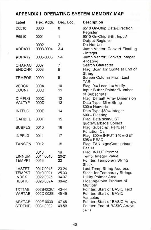
APPENDIX I OPERATING SYSTEM MEMORY MAP
Label
D6510
R6510
ADRAY1
ADRAY2
CHARAC
ENDCHR
TRMPOS
VERCK
COUNT
DIMFLG
VALTYP
INTFLG
GARBFL
SUBFLG
INPFLG
TANSGN
LINNUM
TEMPPT
LASTPT
TEMPST
INDEX
RESHC
TXTTAB
VARTAB
ARYTAB
STREND
Hex. Addr.
0000
0001
0002
0003-0004
0005-0006
0007
0008
0009
OOOA
000 B
OOOC
000D
000E
000F
0010
0011
0012
0013
0014-0015
0016
0017-0013
0019-0021
0022-0025
0026-002A
002B-002C
OO2DO02E
002F-0030
0031-0032
Dec. Loc.
0
1
2
3-4
5-6
7
&
g
10
11
12
13
14
15
16
17
ta
19
20-21
22
23-24
25-33
34-37
38-42
43-44
45-46
47-48
49-5C
Description
6510 On-Chip Data-Direction
Register
6510 On-Chip 8-Bit Input/
Output Register
Do Not Use
Jump Vector: Convert Floating
- Integer
Jump Vector: Convert Integer
-Floating
Search Character
Flag: Scan 1or Quote at End of
String
Screen Column From Last
TAB
Fiag: 0= Load 1 = Verify
Input Buffer Pointer/Number
of Subscripts
Flag: Default Array Dimension
Data Type; $ff = String
$00= Numeric
Data Type:$80 = Integer
$00= Floating
Flag: Data scan/LlST
quote/Garbage Collect
Flag: Subscript Ref/User
Function Call
Flag: $00= INPUT $40= GET
S98=READ
Flag; TAN sign/Comparison
Result
Flag: INPUT Prompt
Temp: Integer Value
Pointer: Temporary String
Stack
Last Temp String Address
Stack for Temporary Strings
Utility Pointer Area
Floating-Point Product of
Multiply
Pointer: Start of BASIC Text
Pointer: Start of BASIC
Variables
Pointer Start of BASIC Arrays
Pointer End of BASIC Arrays
40

Label
FRETOP
FRESPC
MEMSIZ
CURLIN
OLDUN
OLDTXT
DATLIN
DATPTR
INPPTR
VARNAM
VARPNT
FORPNT
FACEXP
FACHO
FACSGN
3GNFLG
BITS
ARGEXP
ARGHO
ARGSGN
ARISGN
FACOV
RODBS
RODBE
IRQTMP
ENABL
Hex. Addr.
0033-0034
00350036
0037-0038
0039-003A
003B-003C
003D-003E
003F-0040
0041-0042
00430044
0045-0046
0047-0048
0049-004A
004B-0060
0061
0062-0065
0066
0067
0068
0069
006A-006D
006 E
006F
0070
029 D
029 E
029F-02A0
02A1
02A2-02FF
02A6
02A7-02FF
Dec. Loc.
51-52
53-54
55-56
57-58
59-60
61-62
6364
65-66
67 68
69-70
71-72
73-74
75-96
97
98-101
102
103
104
105
106-109
110
111
112
669
670
671-672
673
674-677
678
679-767
Description
Pointer; Bottom of String
Storage
Utility String Pointer
Pointer: Highest Address
Used by BASIC
Current BASIC Line Number
Previous BASIC Line Number
Pointer: BASIC Statement for
CO NT
Current DATA Line Number
Pointer: Current DATA Item
Address
Vector: INPUT Routine
Current BASIC Variable Name
Pointer: Current BASIC
Variable Data
Pointer: Index Variable for
FOR/NEXT
Temp Pointer/Data Area
Floating-point Accumulator
#1: Exponent
Floating Accura #1: Mantissa
Floating Accum. #1: Sign
Pointer: Series Evaluation
Constant
Floating Accum. #1: Overflow
Digit
Floating-Point Accumulator
#2: Exponent
Floating Accum. #2: Mantissa
Floating Accum, #2: Sign
Sign Comparison Result:
Accum. #1 vs #2
Floating Accum. #1. Low-
Order (Rounding)
RS-232 Start of Output Buffer
(Page)
RS-232 Index to End of Output
Buffer
Holds IRQ Vector During Tape
I/O
RS-232 Current Enabled
Interrupts
Cassette Temp Data Area
Flag: 0= NTSC Video 1 = PAL
Video
Not Used
41

Label Hex, Addr. Dec, Loc.
I ERROR 0300-0301 768-769
IMAIN
ICRNCH
IQPLOP
IGONE
IEVAL
SAREG
SXREG
SYREG
SPREG
USRPOK
USRADD
CINV
CBINV
NMINV
IOPEN
ICLOSE
ICHKIN
ICKOUT
ICLRCH
I BASIN
IBSOUT
I STOP
IGETIN
tCLALL
USRCMD
ILOAD
ISAVE
TBUFFR
0302-0303
0304-0305
0306-0307
0308-0309
030A-030B
030C
030D
030 E
030 F
0310-0313
0314-0315
0314-0315
0316-0317
0318-0319
031A-031B
031C-031D031E-031F
0320-0321
0322-0323
0324-0325
0326-0327
0328-0329
032A-032B
032C-032D
032E-032F
0330-0331
0332-0333
033C-03FB
770-771
772-773
774-775
776-777
778-779
780
781
782
7S3
784787
785-786
788-789
790-791
792-793
794-795
796-797
798-799
800-801
802-803
804-805
806-807
808-809
810-811
812-813
814-815
816-817
818-819
828-1019
Description
Vector: Print BASIC Error
Message
Vector: BASIC Warm Start
Vector: Tokenize BASIC Text
Vector: BASIC Text LIST
Vector: BASIC Char Dispatch
Vector; BASIC Token
Evaluation
Storage for 6502 .A Register
Storage for 6502 .X Register
Storage for 6502 .Y Register
Storage for 6502 .SP Register
USR Function Jump Instr ($4c}
USR Function Jump Address
Vector: Hardware IRQ
Interrupt
Vector: SRK Instr. Interrupt
Vector: Non-Maskable
Interrupt
Open a Logical File
Close a Specified Logical File
Kernal CHK1N Routine Vector
Open Channel for Output
Close Input and Output
Channels
Kernal CHRIN Routine Vector
Kernal CHROUT Routine
Vector
Scan Stop Key
Get Character from Keyboard
Queue (Keyboard Buffer)
Close a Specified Logical File
User-Defined Vector
Load RAM from a Device
Save RAM to a Device
Tape I/O Buffer
42

Label Hex. Addr. Dec. Loc.
ViCSCN 0400-07FF 1024-2047
0400-07E7 1024-2023
07F8-07FF 2040-2047
0800-9FFF 2048-40959
S000-9FFF 32768-40959
AO0O-BFFF 40960-49151
COOO-CFFF 49152-53247
DOOO-DFFF 53248-57343
EOOO-FFFF 57344-65535
Description
1024 Byte Screen Memory
Area
Video Matrix: 25 Lines x 40
Columns
Sprite Data Pointers
Normal SAStC Program Space
Optional Cartridge ROM - 8192
Bytes
BASIC ROM - 8192 Bytes (or
8K RAM)
RAM - 4096 Bytes
Input/Output Devices and
Color RAM or Character
Generator ROM or RAM - 4096
Bytes
Kernal ROM - 8192 Bytes (or
8K RAM)
43

APPENDIX II INPUT/OUTPUT REGISTER MAP
Hex. Decimal Bits Description
0000 0 0-7 MOS 6510 Data Direction Register
0001 1
Bit a 1:0utput Bit = 0: Input x = Don't Care
MOS 6510 Micro-Processor On-Chip I/O Port
d000-
dooo
dooi
d002
d003
d004
d005
d006
d007
d008
d009
dOOa
dOOb
dOOc
dOOd
dOOe
dOOf
d010
dO11
dO12
dO13
d0i4
dO15
dO16
dO2e
53248
53249
53250
53251
53252
53253
53254
53255
53256
53257
53258
53259
53260
53261
53262
53263
53264
53265
53266
53267
53268
53269
53270
0
i
2
3
4
5
6-7
/LORAM Signal (0 = Switch BASIC ROM Out)
/HIRAM Signal (0 = Switch Kernal ROM Out}
/CHAREN Signal (0= Switch Char. ROM In)
Cassette Data Output Line
Cassette Switch Sense 1 = Switch Closed
Cassette Motor Control 1 = OFF 0 = ON
Undefined
5324B-54271 MOS 6567 Video Interface Controller (VIC)
7
6
5
A
3
2-0
7-6
5
Sprite 0 X Pos
Sprite 0 Y Pos
Sprite 1 X Pos
Sprite 1 Y Pos
Sprite 2 X Pos
Sprite 2 Y Pos
Sprite 3 X POS
Sprite 3 Y Pos
Sprite 4 X Pos
Sprite 4 Y Pos
Sprite 5 X Pos
Sprite 5 Y Pos
Sprite 6 X Pos
Sprite 6 Y Pos
Sprite 7 X Pos
Sprite 7 Y Pos
Sprites 0-7 X Pos (msb of X coord.)
VIC Control Register
Raster Compare: (Bit 8) See 53266
Extended Color Text Mode: l= Enable
Bit-Map ModeH = Enable
Blank Screen to Border Color: 0= Blank
Select 24/25 Row Text Display: 1 = 25 Rows
Smooth Scroll to Y Dot-Position (0-7)
Read Raster / Write Raster Value for Compare
IRQ
Light-Pen Latch X Pos
Light-Pen Latch Y Pos
Sprite Display Enable: 1= Enable
VIC Control Register
Unused
Reset VIC Chip: 1 = Reset 0= Normal
44
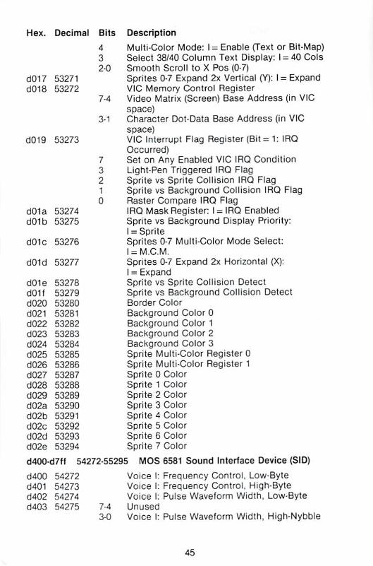
Hex. Decimal Bits Description
d0i7
d0i8
3019
dOia
dO1b
dOic
dO1d
dO1e
dOif
d020
d02i
dO22
dO23
dO24
dO25
dO26
dO27
6028
dO29
d02a
dO2b
d02c
dO2d
d02e
53271
53272
53273
53274
53275
53276
53277
53278
53279
53280
53281
53282
53283
53284
53285
53286
53287
53288
53289
53290
53291
53292
53293
53294
4
3
20
7-4
3-1
7
3
2
*
0
Multi-Color Mode: I- Enable (Text or Bit-Map)
Select 38/40 Column Text Display; I = 40 Cols
Smooth Scroll to X Pos (0-7)
Sprites 0-7 Expand 2x Vertical (Y): I - Expand
VIC Memory Control Register
Video Matrix (Screen) Base Address (in VIC
space)
Character Dot-Data Base Address (in VIC
space)
VIC Interrupt Flag Register (Bit = 1: IRQ
Occurred)
Set on Any Enabled VIC IRQ Condition
Light-Pen Triggered IRQ Flag
Sprite vs Sprite Collision IRQ Flag
Sprite vs Background Collision IRQ Flag
Raster Compare IRQ Flag
IRQ Mask Register: 1 — IRQ Enabled
Sprite vs Background Display Priority:
1 = Sprite
Sprites 0-7 Multi-Color Mode Select:
I = M.C.M.
Sprites 0-7 Expand 2x Horizontal (X):
1 = Expand
Sprite vs Sprite Collision Detect
Sprite vs Background Collision Detect
Border Color
Background Color 0
Background Color 1
Background Color 2
Background Color 3
Sprite Multi-Color Register 0
Sprite Multi-Color Register 1
Sprite 0 Color
Sprite 1 Color
Sprite 2 Color
Sprite 3 Color
Sprite 4 Color
Sprite 5 Color
Sprite 6 Color
Sprite 7 Color
d400-d7ff 54272-55295 MOS 6581 Sound Interface Device (SID)
cf400 54272
d401 54273
d402 54274
d403 54275 7-4
3-0
Voice I: Frequency Control, Low-Byte
Voice I: Frequency Control. High-Byte
Voice !: Pulse Waveform Width, Low-Byte
Unused
Voice 1: Pulse Waveform Width, High-Nybble
45
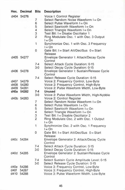
Hex. Decimal
d404 54276
d405 54277
d406 54278
d407 54279
d408 54280
d409 54281
d40a 54282
d40b 54283
d40c 54284
d40d 54285
d40e 54286
d40f 54287
d4iO 54288
Bits Description
Voice i: Control Register
7 Select Random Noise Waveform l = On
6 Select Pulse Waveform l = On
5 Select Sawtooth Waveform I = On
4 Select Triangle Waveform I = On
: Tesl Bit: I = Disabe Oscillator 1
2 Ring Modulate Osc. 1 with Osc. 3 Output
l = On
1 Synchronize Osc. 1 with Osc. 3 Frequency
l = On
0 Gate Bit: I = Start AtUDec/Sus 0= Start
Release
Envelope Generator I: Attack/Decay Cycle
Control
7-4 Select Attack Cycle Duration: 0-15
3-0 Select Decay Cycle Duration: 0-15
Envelope Generator I: Sustain/Release Cycle
Control
7-4 Select Release Cycle Duration: 0-15
Voice 2: Frequency Control, Low-Byte
Voice 2: Frequency Control, High-Byte
Voice 2: Pulse Waveform Width. Low-Byte
7-4 Unused
3-0 Voice 2: Pulse Waveform Width. High-Nybble
Voice 2: Control Register
7 Select Random Noise Waveform l = On
6 Select Pulse Waveform l = On
5 Select Sawtooth Waveform l = On
4 Select Triangle Waveform I = On
Test Bit: I = Disable Oscillator 2
2 Ring Modulate Osc 2 with Osc. 1 Output
I^On
1 Synchronize Osc. 2 with Osc. 1 Frequency
I-On
0 Gate Bit: i = Start Att/Dec/Sus 0 = Start
Release
Envelope Generator 2: Attack/Decay Cycle
Control
7-4 Select Attack Cycle Duration: 0-15
3-0 Select Decay Cycle Duration; 0-15
Envelope Generator 2: Sustain/Release Cycle
Control
7-4 Select Sustain Cycle Amplitude Level; 0 15
3-0 Select Release Cycle Duration: 0-15
Voice 3: Frequency Control, Low-Byte
Voice 3: Frequency Control. High-Byte
Voice 3: Pulse Waveform Width, Low-Byte

Hex. Decimal Bits Description
d411 54289 7-4 Unused
3-0 Voice 3: Pulse Waveform Width, High-Nybble
d4i2 54290 Voice 3: Control Register
7 Select Random Noise Waveform l = On
Select Pulse Waveform l = On
5 Select Sawtooth Waveform I = On
4 Select Triangle Waveform l = On
3 Test Bit: I = Disable Oscillator 3
2 Ring Modulate Osa 3 with Osc. 2 Output
l = On
Synchronize Osc. 3 with Osc. 2 Frequency
l = On
0 Gate Bit: I = Stan Att/Dec/Sus 0 = Start
Release
d413 54291 Envelope Generator 3: AttackyDecay Cycle
Control
7-4 Select Sustain Cycte Duration: 0-15
3-0 Select Release Cycle Duration: 0-15
d414 54292 Envelope Generator Sustain/Release Cycle
Control
7-4 Select Sustain Cycle Amplitude Level: 0-15
3-0 Select Release Cycle Duration: 0-15
d415 54293 Filter Cutoff Frequency: Low-Nybbie (Bits 2-0)
d416 54294 Filter Cutoff Frequency: High-Byte
d417 54295 Filter Resonance Control/Voice Input Control
7-4 Select Filter Resonance: Min = 0 Max = 15
3 Filter External Input: I = Yes 0=No
2 Filter Voice 3 Output: I = Yes 0=No
1 Filter Voice 2 Output: I = Yes 0=No
0 Filter Voice 1 Output: I = Yes 0 = No
d418 54296 Select Filter Mode and Volume
7 Cut-Off Voice 3 Output; I = Off 0 = On
6 Select Filter High-Pass Mode: I-On
5 Select Filter Band-Pass Mode: I-On
4 Select Filter Low-Pass Mode: l = On
3-0 Select Output Volume: OFF=0 Max =15
d4i9 54297 Analog/Digital Converter Game Paddle 1
(0-255)
d41A 54298 Analoc^Digital Converter: Game Paddle 2
(0-255)
d41B 54299 Oscillator 3 Random Number Generator
d4iC 54300 Envelope Generator 3 Output
d500-d7fl 54528-55295 SID Register Images
d800-dbff 55296-56319 Color Cntrl RAM (Only Bits 3-0 Present)
dcOO-dcff 56320-56335 MOS 6526 Complex Interlace Adapter
CIA)#1
4?

Hex. Decimal Bits
dcOO 56320
70
7-6
dcO1
dcO2
dcO3
dcO4
dcO5
dcO6
dcO7
dcOB
dcO9
dcOa
dcOb
dcOc
dcOd
54321
56322
56323
56324
56325
56326
56327
56328
56329
56330
56331
56332
56333
4
3-2
3-0
7-0
4
3-2
3-0
3
2
1
0
Description
Data Port A (Keyboard Joystick Paddles):
Game Port 2
Write Keyboard Column Values for Keyboard
Scan
Select Paddle Input Port: 01 = Port 1
10= Port 2
Joystick-2 Fire Button: 0= Fire
Paddle Fire Buttons: 0= Fire
Joystick-2 Direction: Bit = 1 Open Sw, Bit = 0
Closed
Data Port B (Keyboard Joystick Paddles
Lightpen)
Read Keyboard Row Values for Kybrd Scan
Joystick-1 Fire Button/Ughtpen Trigger
(O= Fire)
Paddle Fire Buttons: 0- Fire
Joystick-1 Direction: Bit= 1 Open Sw. Bit = 0
Closed
Data Direction Register -Pod A (56320)
Data Direction Register-Port B (56321)
Tinner A: Low-Byte
Timer A: High Byte
Timer B: Low-Byte
Timer B: High-Byte
Time-of-Day Clock: 1/10 Seconds
Time-of-Day Clock: Seconds
Time-of-Day Clock: Minutes
Time-of-Day Clock: Hours + AM/PM Flag
(Bit 7)
Synchronous Serial I/O Data Buffer
CIA Interrupt Control Reg. {Read Flags/Write
Mask)
IRQ Flag (I = IRQ OccurredyMasK Set Minus
Clear Flag
FLAG1 IRQ {Cassette Read/Serial IEEE SRQ
Input)
Serial Port Interrupt
Time-of-Day Alarm Interrupt
Tinner B Underflow interrupt
Timer A Underflow Interrupt
48

Hex. Decimal Bits Description
dcOe 56334 CIA Control Register A
7 Time-of-Day Clock Frequency: 1 = 50 Hz
0=60 Hz
6 Serial Port Mode; I = Output 0= Input
5 Time A Counts: I = CNT Signals 0= System
02 Clock
4 Force-Load Timer A: I = YES
3 Time A Run Mode: I = Once 0 = Continuous
2 Timer A Output Mode to PB6: I = Toggle
0= Pulse
1 Time A Output to PB6: 1 = Yes 0= No
0 Start/Stop Time A: 1= Start 0 = Stop
dcOf 56335 CIA Control Register B
7 Set TOD Alarm/Clock: 1 = Alarm 0= Clock
6-5 Time B - Mode Select:
00 = Count System 02 Clock Pulses
01 = Count Positive CNT Transitions
10 = Count Timer A Underflow Pulses
11 = Count Timer A Underflows While CNT
Positive
4-0 Same as Control Register A: for Timer B
ddOO-ddff 56576-56591 MOS 6526 Complex tnterface Adapter
(CIA) #2
ddOO 56576 Data Port A (Serial IEEE, RS-232, VIC Memory
Ctl)
7 Serial IEEE Data Input
6 Serial IEEE Clock Pulse Input
5 Seriai IEEE Data Output
4 Serial IEEE Clock Pulse Output
3 Serial IEEE ATN Signal Output
2 RS-232 Data Output (User Port)
1-0 VIC Chip System Memory Bank Select
(Default =11)
ddO1 56577 Data Port B (User Port/RS-232 Signals)
7 User / RS-232 Data Set Ready
6 User / RS-232 Clear to Send
5 User - Undefined
4 User / RS-232 Carrier Detect
3 User / RS-232 Ring Indicator
2 User / RS 232 Data Terminal Ready
1 User / RS-232 Request to Send
0 User / RS-232 Received Data
/FLAG Userf RS-232 Receive: Detect Start-Bit (IRQ
Flag)
49

Hex. Decimal Bits
dcO2 56578
dcO3 56579
dcO4 56580
dcO5 56581
dcO6 56582
dcO7 56583
dcO8 56584
dcO9 56585
dcOa 56586
dcOb 56587
dcOc 56588
dcOd 56539
A
3
2
1
0
dcOe 56590
dcOf 56591
Description
Data Direction Register -Port A (56320)
Data Direction Register -Port B 456321)
Timer A: Low-Byte
Timer A: High-Byte
Timer B: Low-Byte
Timer B: High-Byte
Time-of-Day Clock: 1/10 Seconds
Time-of-Day Clock: Seconds
Time-of-Day Clock: Minutes
Time-of-Day Clock; Hours + AM/PM Flag
(Bit 7)
Synchronous Serial I/O Data Buffer
CIA Interrupt Control Reg. (Read Flags/Write
Mask)
NMI Flag 0= NM1 OccurredVMask Set-Clear
Flag
FLAG2 NMI: Detects Start-Bit on Recv
Synchronous Serial Port Interrupt
Trme of-Day Alarm Interrupt
Timer B Interrupt
Timer A Interrupt
CIA Control Register A (Same Format at
56334}
CIA Control Register B (Same Format at
56335)
deOQ-defi 56832-57087 Reserved for Future t/O Expansion
dfOQ-dffi 57088-57343 Reserved for Future I/O Expansion
50

APPENDIX III DESCRIPTION OF FILES ON THE
RELEASE DISK
ASSEMBLER64
BOOT ALL
CROSSREF64
DOS 5.1
DOS WEDGE64
EDITOR64
See Section 7. This is the actual assembler
program which loads into low memory and
assembles the files which were created by the
EDITOR program. To load the assembler, type
LOAD +1ASSEMBLER64",8 or use the wedge load
command; then type RUN. Any source text files
not previousJy saved will be lost since the
assembler toads into the same area used.
This program loads and starts the DOS WEDGE,
the HI-LOADER, and the EDITOR all at the same
time. These three programs reside in different
areas in memory, allowing their use without
having to reload before switching programs.
This program is used to print out the cross
reference listing created by the assembler when
that option is specified at assembly time. The
program loads into low memory by using the
LOAD L'CROSSREFB4",8 command and is started
by typing RUN.
This file contains the machine code for the
wedge program. It is loaded automatically by
running the DOS WEDGE64 program.
See Section 5. This program is the "boot loader"
for the DOS 5.1 wedge program. It is the first
program on the disk so that the LOAD "*'\B
command can be used. After the program is
loaded, type RUN and the wedge will be loaded
and activated.
See Section 6. This program is used to create
and modify the source code files which will later
be assembled. To load the editor, type LOAD
"EOITOR64",8,1. After the program is loaded,
type SYS 49152 to activate. Then type NEW to
clear the pointers before proceeding to create or
edit any files. Be sure to save the source code
file using the PUT command before loading the
assembler.
51

LOLOADER64
and
HILOADER64
MONITORS8000
and
MON1TOR$COOO
See Section 8. These two programs are used toload the sequential records which are created by
the assembler as its output or object file. When
one of these programs is run, it loads the object
file into memory in the specified location as true
machine code which can be executed. The only
difference between the two programs is that
LOLOADER loads at hex $0800 and HILOADER
64 loads a! hex SC800. They are both included in
case one of them interferes with the intended
location for the machine code to reside.
To load the S0800 version, type LOAD
"LOLOADER641'.8 and then type RUN. To load
the SC800 version, type LOAD "HILOADER64",8,1
and then type SYS51200.
See Section 9. These two monitor porgrams are
identical in function and are used primarily forload and save binary machine code files in their
executable form.
They also allow the programmer many useful
commands for examining and changing programs
without having to run the whole assembly
process. The first loads at hex $8000 by typingLOAD "MONITOR$8000",8,1 and is started by
typing SYS32768. The second loads at hex $C000by typing LOAD ■■MONITOR$C000",8,1 and is
started by typing SYS49152.
52

APPENDIX IV 6500 SERIES MICROPROCESSORINSTRUCTION SET OPCODES
ADC Add with Carry to
Accumulator
AND "AND11 to AccumulatorASL Shi1t Left One Bit
{Memory or Accumulator)
BCC Branch on Carry Dear
BCS Branch on Carry Set
BEQ Branch on Zero Result
BIT Test Bits in Memory with
Accumulator
BMI Branch on Result Minus
BNE Branch on Result not Zero
BPL Branch on Result Plus
BRK Force an Interrupt or Break
BVC Branch on Overflow Clear
BVS Branch on Overflow Set
CLC Clear Carry Flag
CLD Clear Decimal Mode
CLJ Clear Interrupt Disable Bit
CLV Clear Overflow Flag
CMP Compare Memory and
Accumulator
CPX Compare Memory and
Index Y
CPY Compare Memory and
Index Y
DEC Decrement Memory by One
DEX Decrement Index X by One
DEY Decrement Index Y by One
EOR Exclusive-QR Memory with
Accumulator
INC Increment Memroy by One
INX Increment X by One
INY Increment Y by One
JMP Jump to New Location
JSR Jump to New Location
Saving Return Address
LDA Transfer Memory to
Accumulator
LDX Transfer Memory to Index X
LDY Transfer Memory to Index Y
LSR Shift One Bit Right (Memory
or Accumulator)
53

NOP Do Nothing - No Operation
ORA "OR" Memory with
Accumulator
PHA Push Accumulator on Stack
PHP Push Processor Status on
Stack
PLA Pull Accumulator From Stack
PLP Pull Processor From Stack
ROL Rotate One Bit Left (Memory
or Accumulator)
ROR Rotate One Bit Right
(Memory or Accumulator)
RTI Return From Interrupt
RTS Return From Subroutine
SBC Subtract Memory and Carry
From Accumulator
SEC Set Carry Flag
SED Set Decimal Mode
SEI Set Interrupt Disable Status
STA Store Accumulator in
Memory
STX Store Index X in Memory
STY Store Index Y in Memory
TAX Transfer Accumulator to
Index X
TAY Transfer Accumulator to
Index Y
TSX Transfer Stack to Index X
TXA Transfer Index X to
Accumulator
TXS Transfer Index X to Stack
Register
TYA Transfer Index Y to
Accumulator
54

APPENDIX V A SAMPLE OUTPUT LISTING OF THE
COMMODORE 64 ASSEMBLER
LINE** LOG CODE LINE
00161
00162
00163
00164
00165
00166
00167
00163
00169
00170
00171
00172
00173
00174
00175
00176
00177
00173
00179
00180
00181
00162
00183
001S4
00185
00186
00187
ooisa
00189
00190
00191
00192
00193
00194
00195
00196
00197
00198
00199
00200
00201
00202
00203
00204
00205
00206
00207
0020a
00209
CCE1
CCE1
CCE1
CCE1
CCE1
CCE3
CCE6
CCE8
CCE9
CCEB
CCEB
CCED
CCF0
CCFO
CCFO
CCFO
CCF3
CCF3
CCF3
CCF3
CCF3
CCF5
CCF7
CCF8
CCFB
CCFD
CCFF
CD01
CDO3
CD06
CDO8
CDOA
CD0C
COOE
CD10
CD12
CD12
CD15
CD17
CD18
CD1A
CD1A
CD1A
CD1C
CD1E
CD20
CD22
CD25
CD28
A2 02
BD OE CC
95 7C
CA
10 F8
A5BA
8D 77 CC
4C 4B CF
85 A6
86 A/
BA
BO 01 01
C9E6
FO 04
C9 8C
DO 17
BO 02 01
C9A7
FOOd
C9A4
D0 0C
A5 A6
A2O8
DO 19 CC
FO 11
CA
10 F8
A5 A6
A6 A7
C9 3A
BO 03
4C80 00
4C8A 00
INIT THE
GOOO
WEDGE
MEMORY MANAGER (STARTUP COMES HEP
LOX ff$02
LDA JUMP,X
:MOVE THREE BYTES
STACHRGOT+3.X
DEX
BPLWEDGE
LOA FA
STA SVFA
SAY HELLC .
JMP MSG
;USE CURRENT FA FOR
DEVICE ADDR
;PRINT HELLO (JSR/RTS)
THIS IS WH .". ■.. = ;v :: . IE WORK
START
FRYTWO
FINDIT
FINDC
NOTCMD
STRTS
STA BUFPT
STX BUFPT+1
TSX
LDAS0101.X
CWP#.GONE
BEQ TRY TWO
CMP#,MAIN
BNE NOTCMO
LOA JOIO'.X
CMP#iGONE
BEQ FINDIT
CMPtfcMAIN
BNE NOTCMO
LOA BUFPT
LDX#NCMD-1
COMP CMD.X
BEQ CALLW
DEX
6PL FINDC
LDA BUFPT
LDX BUFPT + 1
CMP*':
BCS STHTS
JMPCHRGOT+7
JMPCHROT + 17
;SAVE A, .X
lACTIVATED CALL IN
■GONE"
;FROM A RUNNING
PROGRAM??
;FROM DIRECT MODE??
; PROGRAM?
;DIRECT?
;GETTHE COMMAND
BACK
:FINO THE COMMAND
: RESTORE REGS
:CMPLETECHRGOT
;TO THE END OF CHRGOT
55

00210 CD28 CALL 1000311 CD28 86 A9 STC CNTDN ;SAVE INDEXS CO2A 8D7ACC STA FLAG ;SAVE THE COMMAND
FOR LATER
00213 CD2D 20A3CE LSR RDFiLE ;GET THE FILENAME ANDLENGTH
nd?14 CD30 A6 A5 LDX CNTDN ;HESTOBE INDEX00215 CD32 A9 27 LDA #,FILE ;SET FILENAME ADDRESS
56

APPENDIX VI EXPLANATION OF ERROR MESSAGES
Error messages are given in the program listing accompanying the
statements in error. The following is a list of all error messages
which might be produced during assembly.
* "A MODE NOT ALLOWED
Following the legal opcode, and one or more spaces, is the letter A
followed by one or more spaces. The assembler is trying to use theaccumulator (A - accumulator mode) as the operand. However, the
opcode in the statement is one which does not allow reference to
the accumulator. Check for a statement labelled A (an illegal
statement), which this statement is referencing. If you were trying to
reference the accumulator, look up the valid operands for theopcode used.
**A,X,Y,S,P RESERVED
A label on a statement is one of the five reserved names (A, X, Y, Sand P). They have special meaning to the assembler and therefore
cannot be used as labels. Use of one of these names will cause this
error message to be printed. No code will be generated for the
statement. The label does not get defined and will appear in the
symbol table as an undefined variable. Reference to such a label
elsewhere in the program will cause error messages to be printed as
if the label were never declared.
■'BRANCH OUT OF RANGE
All of the branch instructions {excluding the two jumps), are
assembled into type bytes of code. One byte is for the opcode and
the other for the address to branch to. The branch is taken relative
to the address of the beginning of the next instruction. If the value
of the byte is 0-127, the branch is forward; if the value is 128-255, the
branch is backward. (A negative branch is in two's complement
form). Therefore, a branch instruction can only branch forward 127 or
backward 128 bytes relative to the beginning o( the next instruction.
If an attempt is made to branch further than these limites, this error
message will be printed. To correct, restructure the program.
"CAN'T EVAL EXPRESSION
In evaluating an expression, the assembler found a character it
couldn't interpret as being par! of a valid expression. This can
happen if the field following an opcode contains special characters
not valid within expressions {i.e. parentheses). Check the operand
field and make sure only valid special characters are within a field{between commas).
57
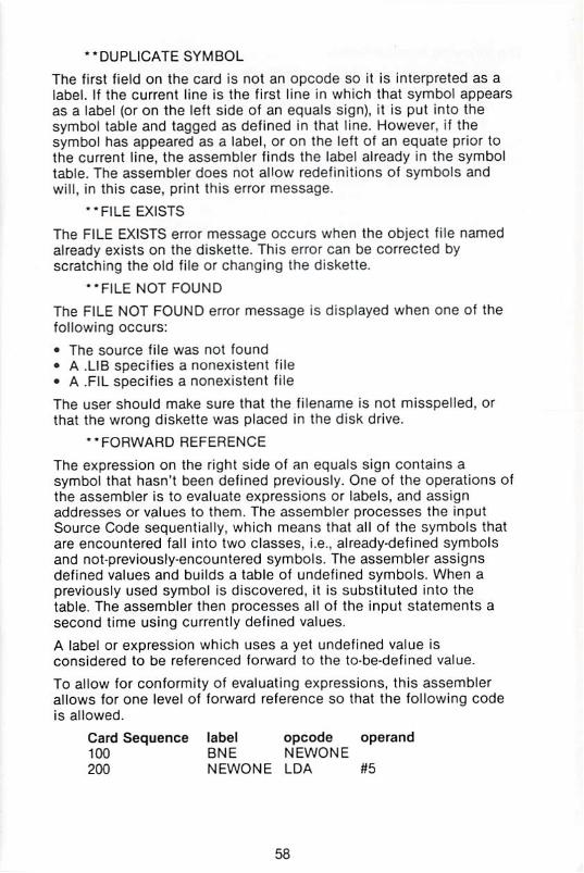
"DUPLICATE SYMBOL
The first field on the card is not an opcode so it is interpreted as a
label. If 1he current line is the first line in which that symbol appears
as a label (or on the left side of an equals sign), it is put into the
symbol table and tagged as defined in that line. However, if the
symbol has appeared ss a label, or on the left of an equate prior to
the current line, the assembler finds the label already in the symbol
table. The assembler does not allow redefinitions of symbols and
will, in this case, print this error message.
"FILE EXISTS
The FILE EXISTS error message occurs when the object file named
already exists on the diskette. This error can be corrected by
scratching the old file or changing the diskette.
"FILE NOT FOUND
The FILE NOT FOUND error message is displayed when one of the
following occurs:
• The source file was not found
• A .LIB specifies a nonexistent file
• A .FIL specifies a nonexistent file
The user should make sure that the filename is not misspelled, or
that the wrong diskette was placed in the disk drive.
"FORWARD REFERENCE
The expression on the right side of an equals sign contains a
symbol that hasn't been defined oreviously. One of the operations of
the assembler is to evaluate expressions or labels, and assign
addresses or values to them. The assembler processes the input
Source Code sequentially, which means that all of the symbols that
are encountered fall into two classes, i.e., already-defined symbols
and not-previously-encountered symbols, The assembler assigns
defined values and builds a table of undefined symbols. When a
previously used symbol is discovered, it is substituted into the
table. The assembler then processes all of the input statements a
second time using currently defined values.
A label or expression which uses a yet undefined value is
considered to be referenced forward to the to-be-defined value.
To aliow ior conformity of evaluating expressions, this assembler
allows for one level of forward reference so that the following code
is allowed.
Card Sequence label opcode operand
100 ' BNE NEWONE200 NEWONE LDA #5
58

The following is not allowed:
Card Sequence label opcode operand
100 BNE NEWONE
200 NEWONE INC NEXT + 5
300 NEXT LDA #5
This feature should not disturb the normal use of labels. The
correction for this problem in this example is:
Card Sequence label opcode operand
100 ' BNE NEWONE300 NEXT LDA #5
301 NEWONE INC NEXT+5
This error may also mean that the value on the right side of the ' = '
is not defined at all in the program, in which case, the cure is the
same as for undefined values.
The assembler cannot process more than one level of computed
forward reference. AM expressions with symbols that appear on the
right side of any equal sign must refer only to previously defined
symbols for the equate to be processed.
"ILLEGAL OPERAND TYPE
After finding an opcode that does not have an implied operand, the
assembler passes the operand field (the next non-blank field
following the opcode) and determines what type of operand it is
(indexed, absolute, etc.). If the type of operand found is not valid for
the opcode, this error message wifl be printed.
Check to see what types of operands are allowed for the opcode
and make sure the form of the operand type is correct (see the
section 1.1. on addressing modes).
Check for the operand field starting with a left parenthesis. If it is
supposed to be an indirect operand, recheck the correct format for
the two types available. If the format was wrong (missing right
parenthesis or index register), this error will be printed. Also check
for missing or wrong index registers in an indexed operand {form:
expression, index register).
"IMPROPER OPCODE
The assembler searches a tine until it finds the first non-blank
character string. If this string is not one of the 56 valid opcodes, it
assumes it is a label and places it in the symbol table. It then
continues parsing for the next non-blank character string. If none
are found, the next line will be read in and the assembly will
continue. However, if a second field is found, it is assumed to be an
opcode (since only one label is allowed per line). If this character
string is not a valid opcode, the error message is displayed.
59

This error can occur it opcodes are misspelled, in which case the
assembler will interpret the opcode as a label (if no label appears on
the card), It will then try to assemble the next field as the opcode. It
there is another field, this error will be printed.
Check for a misspelled opcode or for more than one label on a line.
"INDEXED MUST BE X OR Y
After finding a valid opcode, the assembler looks lor the operand. In
this case, the first character in the operand field is a left
parenthesis. The assembler interprets the -iext field as an indirect
address which, with the exception of the jump statement, must be
indexed by one of the index registers, X or Y. In the erroneous case,
the character that the assembler was trying to interpret as an index
register is not X or Y and this error message is printed.
Check for the operand field starting with a left parenthesis. If it is
supposed to be an indirect operand, recheck the correct format for
the two types available. If the format is wrong (missing right
parenthesis or index registers), this error will be printed, Also, check
for missing or wrong index registers in an indexed operand (form:
expression, index registers).
'" INDIRECT OUT OF RANGE
The assembler recognizes an indirect address by the parentheses
that surround it. If the field following an opcode has parentheses
around it, the assembler will try to assemble it as an indirect
address. If the operand field extends into absolute modet I.e., larger
than 255, (two bytes would be required to specify the address), this
error message will be printed.
This error will only occur if the operand field is in correct form (i.e.,
a index register following the address), and the address field is out
of page zero. To correct this, the address field must refer to page
zero memory. (The implied high order byte is 00).
''INVALID ADDRESS
An address referenced in an instruction, or the address in one of the
assembler directives (.BYTE, .DBYTE., .WORD), is invalid. In the case
of an instruction, the operand that is generated by the assembler
must be greater than or equal to zero, and less than or equal to
SFFFF (2 bytes long). (This excludes relative branches which are
limited to + 127 or - 128 from the next instruction.) If the operand
generates more than two bytes of code or is less than zero, this
error message will be printed. For the .BYTE directive, each operand
is limited to one byte. All address references must be greater than
or equat to zero.
This validity is checked after the operand is evaluated. Check for
values of symbols used in the operand field (see the symbol table
for this information).
60

" LABEL START NEED A-Z
The first non-blank field is not a valid opcode. Therefore, the
assembler tried to interpret it as a label. However, the first character
of the field does not begin with an alphabetic character and the
error message is printed.
Check for an unlabelled statement with only an operand field that
does start with a special character. Also check for an illegal tabel in
the instruction.
"LABEL TOO LONG
All symbols are limited to six characters in length. When parsing,
the assembler looks for one of the separating characters (usually a
blank) to find the end of a label or string. If other than one of these
separators is used, the error message will be printed providing that
the illegal separator causes "the symbol to extend beyond six
characters in length. Check for no spacing between labels and
opcodes. Also, check tor a comment card with a long first word that
doesn't begin with a semicolon. In this case the assembler is trying
to interpret part of the comment as a label.
**NON-ALPHANUMERIC
Labels are made up of one to six alphanumeric digits. The label field
must be separated from the opcode field by one or more blanks. If a
special character or other separator is between the label and the
opcode, this error message might be printed.
Each of the 56 valid opcodes are made up of three alphabetic
characters. They must be separated 1rom the operand field (if one is
necessary) by one or more blanks. If the opcode ends with a special
character {such as a comma), this error message will be printed.
In the case of a lone label or an opcode that needs no operand, they
can be followed directly by a semicolon to denote the rest of the
card as a comment (use of a semicolon tabs the comment out to
the next tab position).
**PC NEGATIVE - RESET 0
An assembled program is loaded into core in the range of position 0
to 64K (65535). This is the extent of the machine. A maximum of two
bytes can be used to define an address. Because there is no such
thing as negative memory, an attempt to reference a negative
position will cause this error and the program counter (or pointer to
the current memory location) to be reset to zero.
When this error occurs, the assembler continues assembling the
code with the new value of the program counter. This could cause
multiple bytes to be assembled into the same locations. Therefore,
care should be taken to keep the program counter within the proper
limits.
61

"RAN OFF END OF CARD
This error message will occur if the assembler is looking for a
needed field and runs off the end of the card (or line image) before
the field is found. The following should be checked for: a valid
opcode field without an operand field on the same card: an opcode
that was thought to take an implied operand! which in fact needed
an operand: an ASCII string that is missing the closing quote (make
sure any embedded quotes are doubled; to have a quote at the end
of the string, there must be three quotes, two for the embedded
quote and one to close off the string): a comma at the end of the
operand field indicates there are more operands to come: if there
aren't other operands, the assembler will run off the current line
looking for them.
"READ ERROR
This message refers to a disk drive read error Refer to your disk
drive manual for a description of these errors and their causes.
•-UNDEFINED DIRECTIVE
All assembler directives begin with a period. If a period is the first
character in a non-blank field, the asembler interprets the following
character string as a directive. If the character string that follows is
not a valid assembler directive, this error message will be printed.
Check for a misspelled directive or a period at the beginning of a
field that is not a directive.
''UNDEFINED SYMBOL
This error is generated by the second pass. If in the first pass the
assembler finds a symbol in the operand field (the field following
the opcode or an equals sign), that has not been defined yet, the
assembler puts the symbol into the table and flags it for
interpretation by pass two. if the symbol is defined (shows up on
the left of an equate or as the first non-blank fiefd in a statement),
pass one will define it and enter it in the symbol table. Therefore, a
symboJ in an operand fieldh found before the definition, will be
defined with a value when pass two assembles it. In this case, the
assembly process can be completed. This is what is meant by one
level of forward reference. (See Forward Reference Error).
However, if pass one doesn't find the symbol as a labei or on the
left of an equate, the assembler never enters it in the symbol table
as a defined symbol. When pass two tries to interpret the operand
field the symbol is in, there ts no corresponding value for the
symbol and the field cannot be interpreted. Therefore, the error
message is printed with no value for the operand.
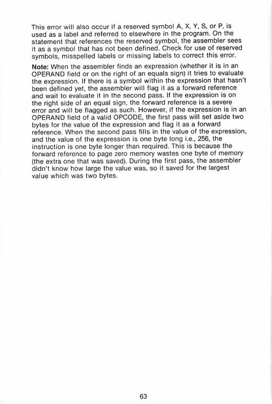
This error will also occur if a reserved symbol A, X, Y, S, or P, is
used as a label and referred to elsewhere in the program. On the
statement that references the reserved symbol, the assembler sees
it as a symbol that has not been defined. Check for use of reserved
symbols, misspelled labels or missing labels to correct this error.
Note: When the assembler finds an expression (whether it is in an
OPERAND field or on the right of an equals sign) it tries to evaluate
the expression. If there is a symbol within the expression that hasn't
been defined yet, the assembler will flag it as a forward reference
and wait to evaluate it in the second pass. If the expression is on
the right side of an equal sign, the forward reference is a severe
error and will be flagged as such. However, if the expression is in an
OPERAND field of a valid OPCODE, the first pass will set aside two
bytes (or the value of the expression and flag it as a forward
reference. When the second pass fills in the value of the expression,
and the value of the expression is one byte long i.e., 256, the
instruction is one byte longer than required. This is because the
forward reference to page zero memory wastes one byte of memory
(the extra one that was saved). During the first pass, the assembler
didn't know how large the value was, so it saved for the largest
value which was two bytes.
63

APPENDIX VII EDITOR64 COMMAND SUMMARY
Command
AUTO n1
AUTO
CHANGE/s1/s2/,n1-n2
CHANG E/s1/s2/
CPUr'FILE"
DELETE n1-n2
FIND/s1/,n1-n2
FlND/si/
FORMAT n1-n2
GET"FILE",n1-n2,n3
GET"FILE"
KILL
LIST
NUMBER nltn2tn3
PUTllFILE"ln1-n2)n3]n4
PUT"FILE"
Description
Starts automatic line numbering
Shuts off auto
Change string in line range
Change string no range
Compacted PUT, unnecessary spaces are
removed
Delete range
Find string in line range
Find string no range
Print formatted
Bring in text from disk file
Short form GET
Disable the editor
List lines of text
Renumber text
Save text on disk file
Save text short form
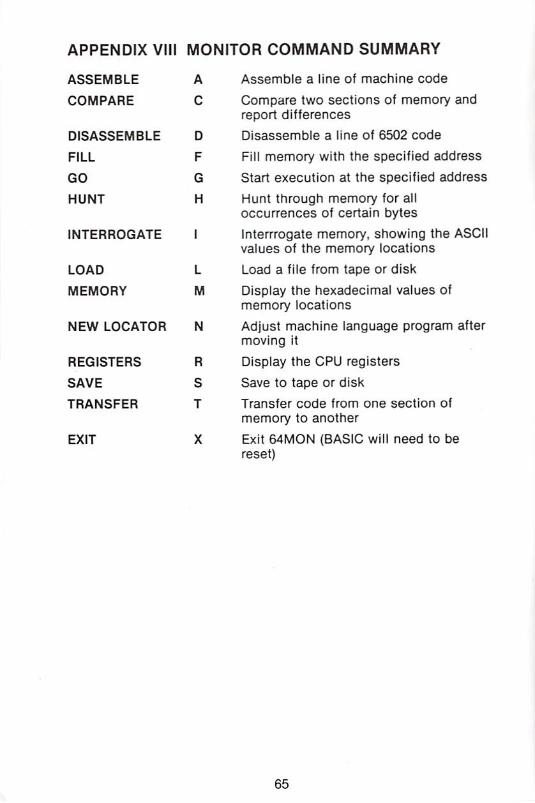
APPENDIX VIII MONITOR COMMAND SUMMARY
ASSEMBLE
COMPARE
DISASSEMBLE
FILL
GO
HUNT
INTERROGATE
LOAD
MEMORY
NEW LOCATOR
REGISTERS
SAVE
TRANSFER
A
c
D
F
G
H
1
L
M
N
R
S
T
EXIT
Assemble a line of machine code
Compare two sections of memory and
report differences
Disassemble a line of 6502 code
Fill memory with the specified address
Start execution at the specified address
Hunt through memory for all
occurrences of certain bytes
interrrogate memory, showing the ASCII
values of the memory locations
Load a file from tape or disk
Display the hexadecimal values of
memory locations
Adjust machine language program after
moving it
Display the CPU registers
Save to tape or disk
Transier code from one section of
memory to another
Exit 64MON (BASIC wil! need to be
reset)
65

COMMAND
@C(dr):newfile([vol]) = oldfile([volJ)
@f(dr)
@N(dr);diskname,id
@R{dr):newfile([vol]) = oldfiie([voi])
©S(dr):filename('X(vol])
@UJ
@$(dr):{filename)(*)([vol])
/filename
%filename
t filename
*■ filename
DESCRIPTION
Current disk status
Copy a file
Initialize a drive
Format a disk
Kill the wedge program
Rename a file
Scratch a file
Reset the DOS
Read the directory
All DOS commands will go to
n where n is 8 to 15 inclusive
Load a file (at BASIC)
Load a file {at its own !oad
address)
Load a file (at BASIC) and run
it
Save a tile
Please Note: 'Vol' is any character enclosed in square brackets; 'dr'
must be 0 (zero) or 1 (one) for the respective drives.
66

t commodore
COMPUTERCommDdore Business Machines. Inc.
1200 Wilson Drive • West. Chester. PA 193B0
Commodore Business Machines. Limited
3370 Pharmacy Avenue • AgmcourL, Ontario. M1W 2K4
Prinled in Hong Kong