the wpc qi standard -...
TRANSCRIPT

Wireless Power
The WPC Qi standard
and
bqTESLATM Solutions
1
Brought to you by
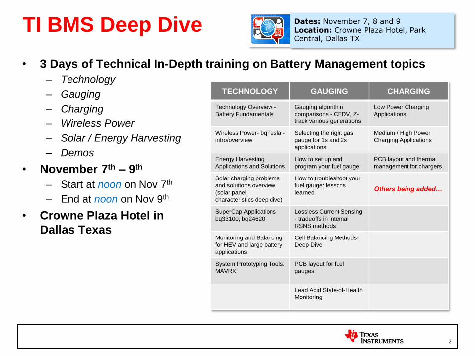
TI BMS Deep Dive
• 3 Days of Technical In-Depth training on Battery Management topics
– Technology
– Gauging
– Charging
– Wireless Power
– Solar / Energy Harvesting
– Demos
• November 7th – 9th
– Start at noon on Nov 7th
– End at noon on Nov 9th
• Crowne Plaza Hotel in
Dallas Texas
Dates: November 7, 8 and 9 Location: Crowne Plaza Hotel, Park Central, Dallas TX
TECHNOLOGY GAUGING CHARGING
Technology Overview -
Battery Fundamentals
Gauging algorithm
comparisons - CEDV, Z-
track various generations
Low Power Charging
Applications
Wireless Power- bqTesla -
intro/overview
Selecting the right gas
gauge for 1s and 2s
applications
Medium / High Power
Charging Applications
Energy Harvesting
Applications and Solutions
How to set up and
program your fuel gauge
PCB layout and thermal
management for chargers
Solar charging problems
and solutions overview
(solar panel
characteristics deep dive)
How to troubleshoot your
fuel gauge: lessons
learned
Others being added…
SuperCap Applications
bq33100, bq24620
Lossless Current Sensing
- tradeoffs in internal
RSNS methods
Monitoring and Balancing
for HEV and large battery
applications
Cell Balancing Methods-
Deep Dive
System Prototyping Tools:
MAVRK
PCB layout for fuel
gauges
Lead Acid State-of-Health
Monitoring
2
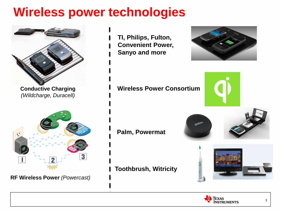
Wireless power technologies
Conductive Charging
(Wildcharge, Duracell)
RF Wireless Power (Powercast)
Toothbrush, Witricity
Palm, Powermat
TI, Philips, Fulton,
Convenient Power,
Sanyo and more
Wireless Power Consortium
3

Wireless Power Consortium (WPC)
Proprietary Solutions Interoperability key to adoption
Industry wide standard for delivering wireless power up to 5W
Aimed to enable interoperability between various charging pads and portable devices
Standard continues to gain traction with increasing list of members (80+)
Compatible devices will be marked with a Qi logo
Broad Industry Support WPC
4
and more…

Market TAM Forecast Standardization / Interoperability will drive growth
5
Aug 17, 2011: IMS Research, a technology consultancy,
released a report on Monday saying by their calculations, the
industry will explode within the coming five years. While only
worth roughly $100 million in 2010, IMS expects the 2016
value to be around $4.5 billion. That’s an annual growth
rate of about 86.5 percent.

Qi Devices Announced in the Market
LG Charging Pad
Sengfei’s Phone & Charging Pad
6
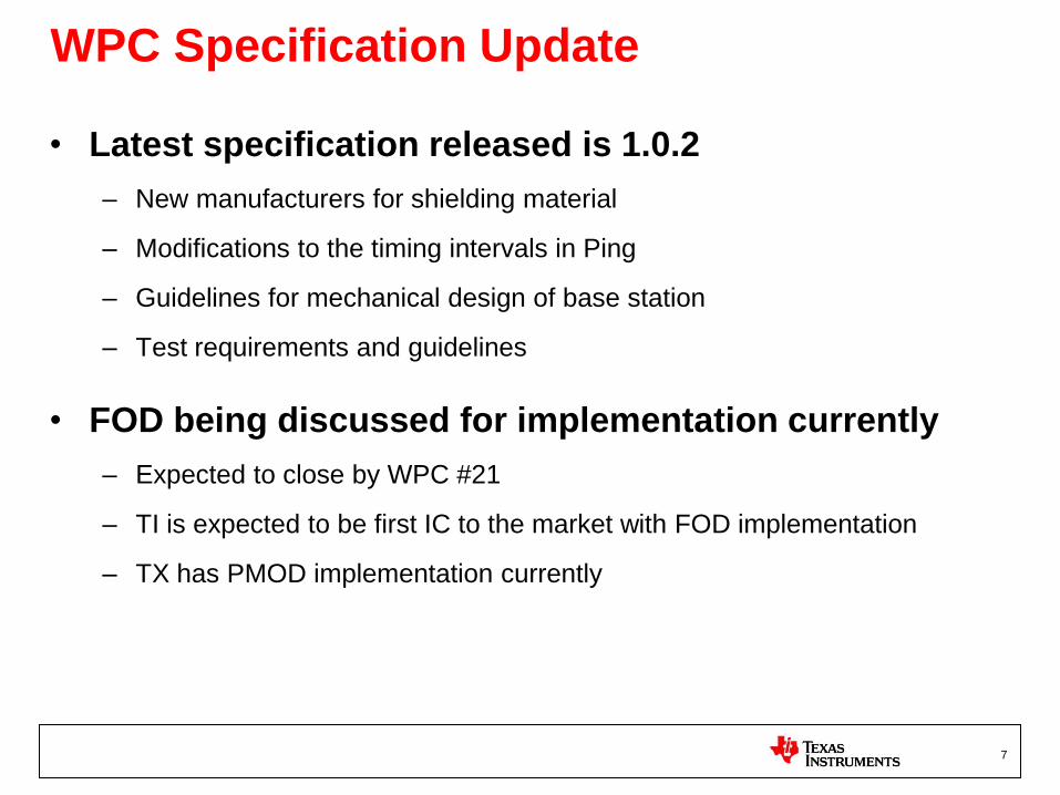
WPC Specification Update
• Latest specification released is 1.0.2
– New manufacturers for shielding material
– Modifications to the timing intervals in Ping
– Guidelines for mechanical design of base station
– Test requirements and guidelines
• FOD being discussed for implementation currently
– Expected to close by WPC #21
– TI is expected to be first IC to the market with FOD implementation
– TX has PMOD implementation currently
7

Inductive Power System Overview
• Power transmitted through shared magnetic field – Transmit coil creates magnetic field
– Receive coil in proximity converts field into voltage
– Shielding material on each side directs field
• Power transferred only when needed – Transmitter waits until its field has been perturbed
– Transmitter sends seek energy and waits for a digital response
– If response is valid, power transfer begins
• Power transferred only at level needed – Receiver constantly monitors power received and delivered
– Transmitter adjusts power sent based on receiver feedback
– If feedback is lost, power transfer stops
I
z < D
D
8
AC to DC Voltage
Conditioning
Communication
and Control
Rectification Drivers Li Ion
Battery
Controller V/I
Sense
Power
Transmitter Receiver
Communication
5V

System Efficiency Dependencies Good Efficiency when coils less than one diameter apart
• Coupling between coils – Distance (z) between coils
– Ratio of diameters (D2 / D) of the two coils
– Physical orientation
• Quality factor – Ratio of inductance to resistance
– Geometric mean of two Q factors
• Uncoupled field has no losses
• Near field allows TX to “see” RX
40% at 1 diameter
1% at 2.5 diameter
0.1% at 4 diameters
0.01% at 6 diameters
Optimal operating distance
Efficiency is Optimal when Coils are Less than One Diameter apart
Higher
efficiency
Lower
efficiency
9

Communication - Basics • Primary side controller must detect that an object is placed on the charging pad.
– When a load is placed on the pad, the primary coil effective impedance changes.
– “Analog ping” occurs to detect the device.
• After an object is detected, must validate that it is WPC-compatible receiver device.
– “Digital Ping” – transmitter sends a longer packet which powers up the RX side controller.
– RX side controller responds with signal strength indicator packet.
– TX controller will send multiple digital pings corresponding to each possible primary coil to identify best positioning of the RX device.
• After object is detected and validated, Power Transfer phase begins.
– RX will send Control Error Packets to increase or decrease power level
• WPC Compliant protocol ensures interoperability.
VOUT, IOUT
Load current is sensed on primary side
– demodulated to get signaling data.
Control processor on RX side will
apply load pulses for signaling
back to TX.
11

Switching Frequency Variation
• System operates near
resonance for improved
efficiency.
• Power control by changing
the frequency, moving along
the resonance curve.
• Modulation using the power
transfer coils establishes the
communications.
• Feedback is transferred to
the primary as error.
12
80 KHz 100 KHz 120 KHz
Operating Point

Free Positioning
(Moving Coil)
WPC version 1.0 TX design freedom
20 October 2011
Free Positioning (Coil Array)
Guided Positioning (Magnetic Attraction)
M
x
y
• Tactical feedback or free positioning
• Alignment or selection of coils
• Activation after detection
Free Positioning (Coil Array)
A
13

bqTESLA Wireless Solutions Gen1 & Gen2
AC to DC Voltage
Conditioning
Controller
Rectification Drivers Load
Controller V/I
Sense
Power
Transmitter Receiver
Communication
RX Solutions • bq51013 (Gen2)
• bq51011 (Gen2)
• bq25046 (Gen1)
• MSP430bq1010 (Gen1)
TX Solutions • bq500210 (Gen2)
• bq500211 (Gen2)
• bq500110 (Gen1)
14

Gen 1* and Gen 2 WPC System Efficiency
*Gen 1 Rx system built using discrete rectification, LDO for voltage conditioning and Micro for communication control.
Gen Rx integrated all three functions into a single IC
15
bqTeslaTM - Gen 1 and Gen 2 System Efficiency with 5-V Receiver
0
10
20
30
40
50
60
70
80
0 0.5 1 1.5 2 2.5 3 3.5 4 4.5 5
Output Power (W)
Effi
cien
cy (
%)
Gen 2 - BQ51013
Gen 1
16
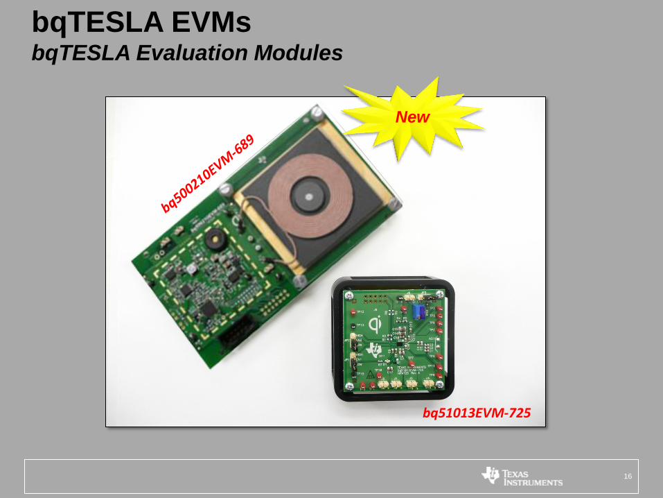
bqTESLA EVMs bqTESLA Evaluation Modules
bq51013EVM-725
New

Qi-compliant coil used w/ EVM kit
40-mm x 30-mm x 0.75-mm
WPC Compliant Receiver Coil
17
WPC Compliant Transmitter Coil

bq51013 “form factor” demo PCB (PR1041)
5 x 15 mm footprint for all RX side circuitry
• Represents what an OEM would design into their actual end-product to
enable wireless power from a QI-compliant charging pad.
18

Receiver Product Roadmap Low Power
Gen1 (bq25046,
MSP430BQ1010) • Eval kit released
• Meets accessory
implementations
Samples
Released
Power Supply Series
Discrete 1st Level of Integration
Z: 1.5mm
BOM Count: 20
16mm
22mm
Z: 1.68mm
BOM Count: 52 5mm
15mm
Direct Charger Series
INTEGRATION
AP
PL
ICA
TIO
N S
ER
IES
Gen2 (bq51k) • Only IC required between
RX coil and output voltage
• 5V Power Supply released
April-2011
• Direct charger released in
Q3-2011
WirelessFEnd
Future
19

bq5101x Receiver Product Schedule
Device Vo-Reg Application Function Availability
PG 2.0 SILICON
bq51013
(Gen 2) 5 V
General Power Supply (Power Level = 2-5W)
Power Supply Released
bq51011
(Gen 2) 5 V
Current Limited Power Supply (Power
Level = 2-5W) Power Supply Released
bq51050
(Gen 2) 4.2V Integrated Li-Ion Battery Charger Charger Sampling
20

bq51013 Gen2 Wireless Power Receiver (RX) – WPC Compliant
• Integrated Wireless Power Receiver Solution with a
5V Regulated Supply
- 93% Overall Peak AC-DC Efficiency
- Full Synchronous Rectifier
- WPC v1.0 Compliant Communication Control
- Output Voltage Conditioning
- Only IC Required Between RX coil and 5V DC Output
Voltage
• Internal Dynamic Rectifier Control for Improved
Load Transient Response
• Supports 20V Max Input
• Low-power Dissipative Rectifier Overvoltage
Clamp (VOVP = 15V)
• Thermal Shutdown
• Single NTC/Control
• 1.9 x 3mm WCSP or 4.5 x 3.5mm QFN (bq51013A)
Package
bq51013EVM
Targeted for low-power (<5W) end equipment:
Cell phones - Digital cameras - Portable media
players - Remote/gaming controllers - Bluetooth,
Headsets - Other portable devices
• Integration reduces total system solution board space and cost
- Provides more power to end equipment and reduces heat dissipation
- Integration into single devices simplifies design and reduces board space
- Allows RX to have interoperability with WPC compliant TX solutions
- Output regulation provides quiet output voltage ready for load
- Simplifies design and reduces board space and cost.
• Consistent power delivered to system load to reduced power sags
• Provides broad range of applications and coils
• Protects the IC from voltages beyond the maximum rating of the IC
• Prevents potential damage device and lowers power dissipation
• Optimal Safety and reduces I/O required to Host
• Saves board space and offers alternate packaging for manufacturing
21

SYSTEM
USB or
AC Adapter
Input
VBUS
PMID
SCL
SDA
INT
HOST
VAUX
SW
BOOT
PGND
CSIN
CSOUT
AUXPWR
DRV
bq24180
DC
O
USB PHY
D+
D- PSEL
CLMP
PM
ID
TS
bq51010
PGND
OUT
EN1
AD
/AD-EN
/CHG
C4
EN2
C1
C2
CBOOT1
CBOOT2
AC1
AC2
COMM1
ILIM
R1
COMM2
CCOMM1
CCOMM2
COIL
BOOT1RECT
C3
R2
VTSB
TS/CTRL
R4
D1
BOOT2
NTC R3
PACK+
PACK-
C5
Status
bq51013 – General 5V Power Supply
• Integrates synchronous rectification, voltage conditioning, communication control
• bq51013 acts as a Power Supply to deliver 5V to the VIN pin of the system charger
• bq51013 automatically selects between AC adapter/USB and wireless input power sources
• Provides adjustable current limit protection and coil overvoltage protection
• Host interface can enable OTG mode via EN1 = ‘1’ or charge termination
with EN1 = EN2 = ‘1’
Adapter Detection
Adapter Enable
30V rating
Receiver Coil
Host Control
of Adapter pin
functionality
Host Control
of End Power/ Fault
5V regulation @ 5W
TS Pin for Vhot and Vcold protection.
Can be used to signal termination or a
fault (CTRL)
Power supply current
limit programmable via
an external resistor.
22
Typical Application Circuit

23
bqTESLA Transmitter (TX) Roadmap
Gen 1 - bq500110 • WPC Compliant Solution
• Analog demodulation
• Half-Bridge Monolithic Power Train
• One controller per bay
• Guided Positioning (Type A1)
Development
Samples
PE
RF
OR
MA
NC
E
Gen 2 Family (bq500xxx) • Digital Demodulation
• 5V Input – bq500211 in Oct11
• Free Positioning (Coil Array) –1Q12
• Single TX w/ multi coil
Future
Dec’10 2011 2012
50% reduction in form factor
BOM Count: 71
~1200mm2 (30 x 40mm)
BOM Count: 160
~2600mm2 (50 x 52mm)
Released!
Gen 2 - bq500210 • WPC Compliant Solution
• Digital Demodulation
• Full-Bridge Monolithic Power Train
• One controller per bay
• Guided Positioning (Type A1)
Released!

bq500xxx Transmitter Schedule
Device VIN Application Function Projected
Release
Single Bay
bq500110
(Gen 1) 19V
Single Bay – 5W
QFN-48 Transmitter Production
bq500210
(Gen 2) 19 V
Single Bay – 5W
QFN-48
Transmitter w/
Digital Demod Production
bq500211
(Gen 2) 5 V
Single Bay – 5W
QFN-48
Transmitter w/
Digital Demod
Samples – Now
Prod – Oct11
24

GEN1: TX System Diagram GEN2: TX System Diagram
• bq500210 Based Designs… – Converts Analog Demod circuit to
Digital Demod circuit • Significant reduction in BOM and Area
– Simplifies Current Sense circuit – no
Current Sense Transformer • Reduces BOM cost and Area
– Simplifies Regulator circuit for Drivers • Reduces cost
– Uses Lower Cost Power FETs
– Uses Lower Cost INA amplifier
– PMOD performance offers improved
Linearity and Sensitivity
– Optional configuration • Use lowest cost MSP430 & TLV70033
to implement “Standby Mode” for
Energy Star
TPS28225
MOSFET DRIVER
bq500xxx
Wireless
Power
Controller
TPS54231 Buck
Regulator
Serial COM
3x OPA4348
74LVC1G3157
Active FILTER
TPS715A01
Linear Regulator
PWM
CSD17308 NexFET
CSD17308 NexFET
INA214 Current
Sense
19Vin
5.5VDC3.3VDC
NTC
Tank/Coil
Assembly
X X
X
25

GEN2 – Digital Communication Demodulation
Gen 1 Gen 2
Gen 2 demodulation removes the current sense transformer and analog
filters and comparators.
26

bq500210 Application Schematic
27
bq500210
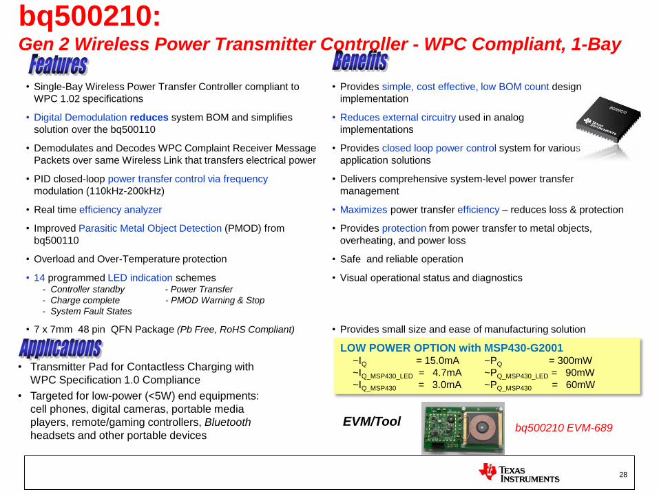
bq500210: Gen 2 Wireless Power Transmitter Controller - WPC Compliant, 1-Bay
bq500210 EVM-689 EVM/Tool
• Transmitter Pad for Contactless Charging with
WPC Specification 1.0 Compliance
• Targeted for low-power (<5W) end equipments:
cell phones, digital cameras, portable media
players, remote/gaming controllers, Bluetooth
headsets and other portable devices
• Single-Bay Wireless Power Transfer Controller compliant to
WPC 1.02 specifications
• Provides simple, cost effective, low BOM count design
implementation
• Digital Demodulation reduces system BOM and simplifies
solution over the bq500110
• Reduces external circuitry used in analog
implementations
• Demodulates and Decodes WPC Complaint Receiver Message
Packets over same Wireless Link that transfers electrical power
• Provides closed loop power control system for various
application solutions
• PID closed-loop power transfer control via frequency
modulation (110kHz-200kHz)
• Delivers comprehensive system-level power transfer
management
• Real time efficiency analyzer • Maximizes power transfer efficiency – reduces loss & protection
• Improved Parasitic Metal Object Detection (PMOD) from
bq500110
• Provides protection from power transfer to metal objects,
overheating, and power loss
• Overload and Over-Temperature protection • Safe and reliable operation
• 14 programmed LED indication schemes - Controller standby - Power Transfer
- Charge complete - PMOD Warning & Stop
- System Fault States
• Visual operational status and diagnostics
• 7 x 7mm 48 pin QFN Package (Pb Free, RoHS Compliant) • Provides small size and ease of manufacturing solution
28
LOW POWER OPTION with MSP430-G2001 ~IQ = 15.0mA ~PQ = 300mW
~IQ_MSP430_LED = 4.7mA ~PQ_MSP430_LED = 90mW
~IQ_MSP430 = 3.0mA ~PQ_MSP430 = 60mW

Gen1 and Gen2 EVM Comparison
Gen 1 EVM Gen 2 EVM bq500110
bq500210
Buzzer 3.3V SWIFT
Regulator
CT
3.3V SWIFT
Regulator
Power Train Power Train MSP430 Analog
Demodulation
BOM Count: 71 ~1200mm2 (30 x 40mm)
BOM Count: 160
~2600mm2 (50 x 52mm)
• Replaced INA214 to INA199A2 (Shunt monitor)
– Drop-in replacement
– Retains high-side sensing
• Replaced CSD17308 to CSD17313 (Power MOSFET): – Smaller and fully released - samples available
• Added TLV70033 (low power LDO) to remove power to bq500210 in standby mode – Reduces Iq to <5mA (w/ LED), or <4mA (no LED)
29

TI Wireless Power Forum
& Wireless Power Web Page
• TI E2E Community-Wireless Power http://e2e.ti.com/support/power_management/wireless_power/default.aspx
• External Forum—available for
entire engineering community
• Ground Rules
– Keep the questions technical in nature,
good question your peers can benefit
from at a later date.
– One question per-post to make it
easer to search.
– Place P/N in Topic with description
of question again to make it easier to search.
– Do not ask pricing or deliver questions
• TI Wireless Power Web Page http://www.ti.com/wirelesspower
30

Magnetic Suppliers and Part Numbers
Partners for RX Coils
– Toko: Chris Seiberlich ([email protected])
– TDK: Keith Itagaki ([email protected])
– Vishay: Tim Shafer ([email protected])
– Mingstar: Alan Liaw ([email protected])
Partners for TX Coils
– Elytone (ECO00260A): Annie Jya ([email protected])
– Toko X1387: Chris Seiberlich ([email protected])
– TDK: Keith Itagaki ([email protected])
– E&E: Darren Simmons ([email protected])
– Vishay: Tim Shafer ([email protected])
– Mingstar: Alen Liaw ([email protected])
– Kolektor-Magma Milivoj Sečan ([email protected])
– TopFlux: Cho Hong Min ([email protected])
31
For technical specs & tutorials: http://www.wirelesspowerconsortium.com
32

33
Thank You!