the value of solid expandable tubulars in cased-hole
TRANSCRIPT
The Value of Solid Expandable Tubulars
in Cased-hole Environments
Dustin M. Dell, Keith Jenkins, Greg Noel and Javier Via Reque
Enventure Global Technology, Houston, Texas
SMRI Spring 2019 Technical Conference 8-9 APRIL 2019
New Orleans, Louisiana, USA
SOLUTION MINING RESEARCH INSTITUTE 105 Apple Valley Circle
Clarks Summit, PA 18411, USA
Telephone: +1 570-585-8092 www.solutionmining.org
Technical Conference
Paper

Solution Mining Research Institute Spring 2019 Technical Conference New Orleans, Louisiana, USA 8-9 APRIL 2019
The Value of Solid Expandable Tubulars in Cased-hole Environments
Dustin M. Dell, Keith Jenkins, Greg Noel and Javier Via Reque Enventure Global Technology, Houston, Texas
Abstract Since its inception in the late nineties, solid expandable tubular technology has saved major and independent operators significant capital whether used in drilling operations or in workover projects. In drilling operations, these systems are used as a contingency string and as a primary casing string planned into the base well design. Incorporating these systems into the initial wellbore plan has reduced the overall costs of some wells by up to 30%. For workover projects, solid expandable tubulars are used to repair and/or reinforce existing casing while minimizing loss of hole size. This feature enables use of the same completion.
Solid expandable technology involves the controlled expansion of solid metal liners in the down hole environment for enhanced drilling, production, completion and remedial operations. As the technology matures, application realms continue to broaden to include the installation of multiple systems in a single wellbore, expansion through milled windows, and use in high-pressure & temperature conditions. In addition, these systems have provided the momentum for operations that result in compelling returns on production-enhancement projects for old/new wells and fields.
This paper will illustrate how the latest solid expandable liners have been applied in existing cavern wells to repair corroded sections of casing while providing the largest internal diameter possible in order to maintain sufficient throughput capacity. Thus, enabling the operator to continue servicing their clients in a timely manner, as well as, extending the life of the asset and saving the cost of drilling a replacement well.
Key words: Caverns for Storage, Remediation, Throughput, Open-Hole, Cased-Hole, Liner
1

Introduction
Even with evolving technology, important issues continue to challenge the oil and gas industry, such as conservation of hole size, hydraulic isolation of selected zones, maximization of well life, and economic feasibility. Addressing these issues with conventional tubular technology has become more difficult, especially in deep-drilling and extended-reach applications, in wells using liner hangers, and in aging wells containing deteriorating casing. The solid expandable tubular systems, a proven technology, successfully address these issues in commercial applications enabling successful solutions that are both innovative and economically viable.
The basic piece of equipment that underlies solid expandable technology is a mechanical expansion device (known as an expansion cone) that is propagated through downhole tubulars using hydraulic pressure. The movement of the cone expands the tubulars to the desired internal and external diameters in a plastic deformation process known as cold-working. This preserves the greatest post expansion burst and collapse values possible.
In drilling applications, a specially designed, expandable liner hanger conserves hole size by eliminating the need for a conventional liner hanger/liner hanger packer, and provides a superior pressure seal compared to conventional technology. In cased wells, expandable casing is clad to existing casing to repair or strengthen the existing casing with minimal decrease in wellbore inside diameter (ID) and flow potential. Solid expandable tubular solutions have been implemented successfully on a global scale in deepwater, shelf, and land wells.2 This retailored paper5 describes the solid expandable tubular system and the technical concepts upon which it is based, an overview of the technology, the challenges that must be overcome, and the commercial applications. The paper then focuses on several recent field installations where cased-hole liners were used to repair wellbores and extend their life.
Technology Overview
Previously published papers have discussed the concepts of solid expandable tubular technology1 and the effect of the expansion process on the system’s tubulars2, 3 and connectors4. In this light, this paper will review the basics of solid expandable tubular technology, with emphasis on how this technology can be applied to remediate wells for subsequent increased productivity.
The Expansion System Operation
The underlying concept of solid expandable casing is cold-working steel tubulars to the required size downhole—a process that is, mechanically, very unstable by its nature. Thus, there exist many technical and operational hurdles to overcome when using the cold-working process in a downhole environment.
An expansion cone mechanically deforms the pipe permanently (Fig. 1). The cone propagates through the tubular by a differential hydraulic pressure across the cone itself and/or by a direct mechanical pull or push force. The differential pressure is applied by pumping through a work-string connected to the cone, and the mechanical force is applied by raising or lowering the work-string. The progress of the cone through the tubular deforms the steel past its elastic yield limit into its plastic deformation region, stopping short of its ultimate yield strength (Fig. 2). In some test cases, expansions of over 25%, based on the ID of the pipe, have been accomplished. Most applications, however, only require expansions of less than 20%.
At the bottom of the system is a chamber containing the expansion cone. This chamber is called the launcher and is constructed of thin-wall, high-strength steel with a wall thickness less than that of the expandable casing. The thinner wall results in a launcher with an outside diameter (OD) that is the same or less than the drift of the previous string of casing. This design enables the launcher to be tripped into the hole through the previous casing string.
An elastomer-wrapped(vulcanized) hanger joint is positioned at the top of the expandable system, just above the launcher for cased-hole applications. The difference in the OD of the expanded tubular and the ID of the base casing allows the elastomer-wrapped expanding pipe to be “clad” (sealed) to the previous casing string. After expansion, the result is expanded pipe with an OD greater than the OD of the launcher (because of the small wall thickness), while the ID of the pipe expands to the same ID of the launcher.
Solid Expandable Tubular Products The new solid expandable tubular technology includes the following products:
• Expandable Open-hole Liner (OHL) system
• Expandable Cased-Hole Liner (CHL) system
• Expandable Liner Hanger (ELH) system
2

Solid Expandable Tubular Nomenclature
Familiarization with the nomenclature for the new solid expandable tubular system is necessary to understand system explanations and application descriptions. An example of solid expandable tubular systems’ nomenclature follows:
7-5/8in(193.7mm) x 9-5/8in(244.5mm). (53.5lb/ft(79.62kg/m)) OHL or CHL
The first dimension is the OD of the expandable casing to be used to create the expandable finished product (7-5/8in(193.7mm)). The second dimension is the OD of the base casing that the expandable system will be expanded inside (9-5/8in(244.5mm)). On some occasions the weight of the base casing may be indicated immediately following the size of the base casing (53.5lb/ft (79.62kg/m)). The name following the system size nomenclature indicates the type of application environment in which the system will be employed (OHL or CHL).
Using the above example, 7-5/8in(193.7mm) x 9-5/8in(244.5mm) (53.5lb/ft(79.62kg/m)) OHL, this nomenclature indicates the following:
• The OD of the expandable casing to be used in this system is 7-5/8in(193.7mm).
• The OD of the base casing in which the system will be sealed is 9-5/8in(244.5mm).
• The weight of the base casing is 53.5lb/ft(79.62kg/m).
• The environment that the expandable system will be employed in is an open hole.
The Expandable Liner Hanger (ELH) system has a somewhat different organization. For example:
• 9-5/8in(53.5lb/ft) Expandable Liner Hanger (ELH)
This nomenclature indicates that the OD of the base casing in which the ELH will be sealed inside is 9-5/8in (244.5mm) (53.5lb/ft(79.62kg/m)). The common liner solid expandable tubular with this hanger is 7in(177.8mm) or 7-5/8in(193.7mm).
Expandable Open-hole Liners System
The OHL system is used to overcome operational problems associated with borehole instabilities, pore-pressure/fracture gradient issues, and the effects of salt or subsalt formations. The OHL is run through the existing casing or liner and positioned in the open-hole. The expandable OHL is then expanded from the bottom up to the top. OHLs are expanded from the bottom up because of the shortening of the liner during expansion and because it is easier to generate greater forces by pumping through and pulling on the work-string than it is by adding weight to the work-string. When the expansion cone reaches the overlap between the expandable OHL and the existing pipe string, the cone expands an elastomer-wrapped hanger joint to provide a permanent seal between the two strings.
Liners are often difficult to position at their planned total depth, and, consequently, may be positioned somewhat higher. A top-down expansion would first anchor the expandable liner in the previous pipe string, and the ensuing expansion would shorten the liner from the bottom up to the top. The shortened, expanded liner may not cover an adequate interval at the bottom of the hole. A bottom-up expansion first anchors the expandable liner at its lowest depth, and the subsequent shortening experienced during the remaining expansion occurs in the overlap. Liner coverage at the bottom of the hole is thus ensured.
Because the work-string is already being pulled out of the hole as a part of the bottom-up expansion operation, additional tensional forces can be added to the work-string, if necessary, to serve as a secondary force for driving the expansion. With a top-down expansion, downward force or additional weight to the work-string would serve as the secondary expansion force, placing the work-string (drill pipe) in compression. Drill collars and heavyweight drill pipe would be needed as part of the work-string to supply additional weight. This approach would only add time to work-string makeup with minimal compressional forces being added in comparison to the tensional forces available. For example, propagation forces in expandable operations when expanding 13-3/8in(339.7mm) casing can approach 300,000lb(136,077.7kg) The casing’s size and mechanical properties typically determine the propagation forces required to expand the liner.
The following steps outline the running sequence for the installation of the expandable OHL (Fig. 3):
1. Drill the hole section to facilitate the expandable liner installation. 2. Run the drill string in the hole with the expandable liner, expansion assembly, and launcher. 3. Cement the expandable liner.
3
4. Install the latch-down plug to facilitate liner expansion. 5. Expand the OHL. 6. Expand the expandable liner hanger joint. 7. Drill out the expandable liner float shoe.
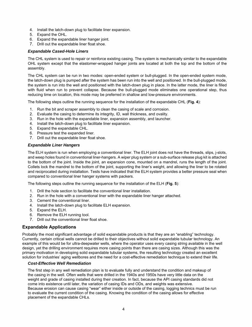
Expandable Cased-Hole Liners
The CHL system is used to repair or reinforce existing casing. The system is mechanically similar to the expandable OHL system except that the elastomer-wrapped hanger joints are located at both the top and the bottom of the assembly.
The CHL system can be run in two modes: open-ended system or bull-plugged. In the open-ended system mode, the latch-down plug is pumped after the system has been run into the well and positioned. In the bull-plugged mode, the system is run into the well and positioned with the latch-down plug in place. In the latter mode, the liner is filled with fluid when run to prevent collapse. Because the bull-plugged mode eliminates one operational step, thus reducing time on location, this mode may be preferred in shallow and low-pressure environments.
The following steps outline the running sequence for the installation of the expandable CHL (Fig. 4):
1. Run the bit and scraper assembly to clean the casing of scale and corrosion. 2. Evaluate the casing to determine its integrity, ID, wall thickness, and ovality. 3. Run in the hole with the expandable liner, expansion assembly, and launcher. 4. Install the latch-down plug to facilitate liner expansion. 5. Expand the expandable CHL. 6. Pressure test the expanded liner. 7. Drill out the expandable liner float shoe.
Expandable Liner Hangers
The ELH system is run when employing a conventional liner. The ELH joint does not have the threads, slips, j-slots, and weep holes found in conventional liner-hangers. A wiper plug system or a sub-surface release plug kit is attached to the bottom of the joint. Inside the joint, an expansion cone, mounted on a mandrel, runs the length of the joint. Collets lock the mandrel to the bottom of the joint, supporting the liner’s weight, and allowing the liner to be rotated and reciprocated during installation. Tests have indicated that the ELH system provides a better pressure seal when compared to conventional liner hanger systems with packers.
The following steps outline the running sequence for the installation of the ELH (Fig. 5):
1. Drill the hole section to facilitate the conventional liner installation. 2. Run in the hole with a conventional liner with the expandable liner hanger attached. 3. Cement the conventional liner. 4. Install the latch-down plug to facilitate ELH expansion. 5. Expand the ELH. 6. Remove the ELH running tool. 7. Drill out the conventional liner float shoe.
Expandable Applications Probably the most significant advantage of solid expandable products is that they are an “enabling” technology. Currently, certain critical wells cannot be drilled to their objectives without solid expandable tubular technology. An example of this would be for ultra-deepwater wells, where the operator uses every casing string available in the well design, yet the drilling environment requires more casing points than there are casing sizes. Although this was the primary motivation in developing solid expandable tubular systems, the resulting technology created an excellent solution for industries’ aging wellbores and the need for a cost-effective remediation technique to extend their life.
Cost-Effective Well Remediation
The first step in any well remediation plan is to evaluate fully and understand the condition and makeup of the casing in the well. Often wells that were drilled in the 1940s and 1950s have very little data on the weight and grade of casing installed during their creation. In fact, because the API casing standards did not come into existence until later, the variation of casing IDs and ODs, and weights was extensive. Because erosion can cause casing “wear” either inside or outside of the casing, logging technics must be run to evaluate the current condition of the casing. Knowing the condition of the casing allows for effective placement of the expandable CHLs.
4

It is critical to have the elastomeric sealing elements of the CHL expanded against pipe of good integrity both inside and out. Placing the liner over casing that currently has a hole or leak path in it does little good if there is severe casing corrosion from the outside of the casing just beyond the end of the expandable solution. The resulting expenditure would only be a temporary remediation.
Using well logs, such as those generated by an ultrasonic acoustic pipe inspection tool, casing can be evaluated to determine its inside and outside integrity, ID, wall thickness, and ovality. At the same time the quality of the cement bond can be evaluated to determine if remedial action is needed to achieve the necessary hydraulic isolation over the interval. Utilizing well logs greatly improves the chance for an effective expandable solution. Alternatively, if the outside condition of the casing is known, a multi- fingered caliper can be used to accurately determine the ID within 0.05in(1.27mm) and the casing’s inside condition. The following case histories summarize wells that used solid expandable tubular technology to address significant operational downhole challenges that demanded the utmost of the mechanical, metallurgical, and physical properties of the post-expanded tubulars. These applications required expanded tubulars hundreds of feet in length, with collapse ratings similar to conventional oil country tubular goods (OCTG), and with enough mechanical integrity to allow the operator to either drill through or traverse the string without incurring significant damage.
Case History 1 Located in Kansas, USA, a natural gas liquids (NGL) storage cavern risked NGL leakage over the entire 1,100ft(335.3m). of 7in(177.8mm) casing into the surrounding formation. To mitigate potential leakage, the following options were available.
• Install a 5-1/2in(139.7mm) standard liner which would restrict the NGL flow annulus and constrain throughput capacity into and out of the cavern, making repair unattractive.
• Drill a new wellbore and solution mine a new cavern, delaying functional operation by 2-3 years.
• Install a 5-1/2in(139.7mm) expandable CHL system.
The decision was to install the expandable CHL in the 7in(177.8mm) base casing (Fig. 6). This option allowed the operator to avoid the costs of drilling and mining a new facility at a cost of approximately $1.0M—plus a delay of 2-3 years. Additionally, in comparison to a standard liner, the expandable CHL allowed for approximately 14% more ID which in-turn optimized overall throughput capacity.
Case History 2
Near Ft. Bend County, Texas, an operator was challenged with 190ft(57.9m) of heavily corroded 9-5/8in(244.5mm) casing. After reviewing the economies of scale, the operator determined that using a conventional scab liner would result in approximately 50% loss in throughput capacity from the cavern well. This would significantly increase the amount of time to process client’s orders, causing them to seek alternate suppliers.
The solution was to use a 7-5/8in(193.7mm) x 9-5/8in(244.5mm) expandable CHL, covering the section of corroded casing (Fig. 7). The post-expanded ID of the liner provided the maximum throughput capacity possible, enabling the operator to continue servicing their clients in a timely manner and saved the cost of drilling a replacement well, extending the life of the asset.
Case History 3 Corrosion in storage cavern wells is a common occurrence. These wells are typically older wells that eventually need remediation in order to continue to be valuable assets. The main challenge has always been finding a solution that would enable the Operator to maintain acceptable throughput capacity.
In this case, in McPherson County, Kansas, a 40ft(12.2m) section of 8-5/8in(219.1mm) casing installed in a storage cavern well was in need of repair due to corrosion meaning the Operator would need a solution to repair the damaged section with the largest Internal Diameter (ID) possible in order to maintain sufficient throughput capacity. Conventional liner solutions would result in approximately 50% loss in throughput capacity from the cavern well.
The issue was resolved using a 7-5/8in(193.7mm) x 8-5/8in(219.1mm) expandable CHL solution, covering the short section of corroded casing. The benefits from this solution echo those illustrated in Case History 2, enabling maximum throughput.
5

Application Evaluation Expandable products are not a universal remedy for all operational problems involving downhole tubulars and are little more than a novelty if cost-effective applications are not the end result. The economics of solid expandable tubular products must work for the long-term benefit of the operator. Careful consideration must be given to the economic feasibility when evaluating candidates for well remediation with solid expandable tubular products. Factors such as replacement cost of the well, lost production, and the direct and indirect costs of the intervention all must be weighed against the benefit of extending the operational life of the well.
Situations that lend themselves to economic feasibility include the following:
• Larger hole size and/or greater mechanical properties for additional production and/or production enhancement.
• Marginal wells that develop leaks. Expandable products are a viable alternative when other remedial techniques such as cement squeezes fail, and the production does not justify running a steel liner over the entire length of the well.
• Zone isolation in an open-hole completion to reduce production of water. Rather than leave behind recoverable reserves when the oil/water ratio becomes unfavorable, expandable products can be used in combination with cement to isolate viable producing intervals from those producing water.
Summary It is shown, via case-by -case scenarios, that utilizing expandable products for corrective remediation in the underground storage industry can be advantageous on many fronts.
As the introduced expandable tubular technology vary in their respective method of installation they serve as a viable solution and garner the momentum for operations that result in compelling returns on production-enhancement and well remediation projects.
The ultimate goal is to maximize throughput and this can be achieved with expandable tubular technology over conventional liner hangers, and as referenced in the aforementioned cases, enabling the operator to continue servicing their clients in a timely manner with minimal non-productive time, saving the cost of drilling a replacement well while extending the operational life of the asset(s).
6

References
1. Filippov, A., et. al.: “Expandable Tubular Solutions,” paper SPE 56500 presented at the 1999 SPE Annual Technical Conference and Exhibition, Houston, Texas, U.S.A., October 1999.
2. Lohoefer C. Lee, and Ben Mathis, Unocal; David Brisco, Halliburton Energy Services; Kevin Waddell, Lev Ring, and Patrick York, Enventure Global Technology: “Expandable Liner Hanger Provides Cost-Effective Alternative Solution,” IADC/SPE 59151, 2000 IADC Drilling Conference, New Orleans, Louisiana, February 2000.
3. Haut, R.C., and Q. Sharif: “Meeting Economic Challenges of Deepwater Drilling with Expandable Tubular Technology,” paper presented at the 1999 Deep Offshore Technology International Conference and Exhibition, Stavanger, Norway, October 1999, 19-21.
4. Brock, Jim, Scott Costa, Grant Prideco; Lev Ring, Enventure Global Technology; Andrei Filippov, Shell Exploration & Production Technology: “An Expanded Horizon,” Harts E&P, February 2000, 115-118.
5. Merritt, R. M., “Casing Remediation – Extending Well Life through the use of Solid Expandable Casing Systems”, Paper MP2002S_Merritt presented at 2002 Spring – Banff SMRI Technical Meeting, Banff, Alberta, Canada, 28 April – 1 May 2002
7

Figures
Fig. 1 - Expansion Cone Used to Expand Solid Expandable Tubulars
8

Fig. 2 – Stress/Strain Curve for Solid Expandable Tubulars
9

Fig. 3 - Operational Running Sequence for Open-Hole Liner (OHL)
10

Fig. 4 - Operational Running Sequence for Cased-Hole Liner (OHL)
11

Fig. 5 - Operational Running Sequence for Expandable Liner Hanger (ELH)
12

Fig.6 - Well Schematic for Case History 1
13

Fig.7 – Well Schematic for Case History 2
14
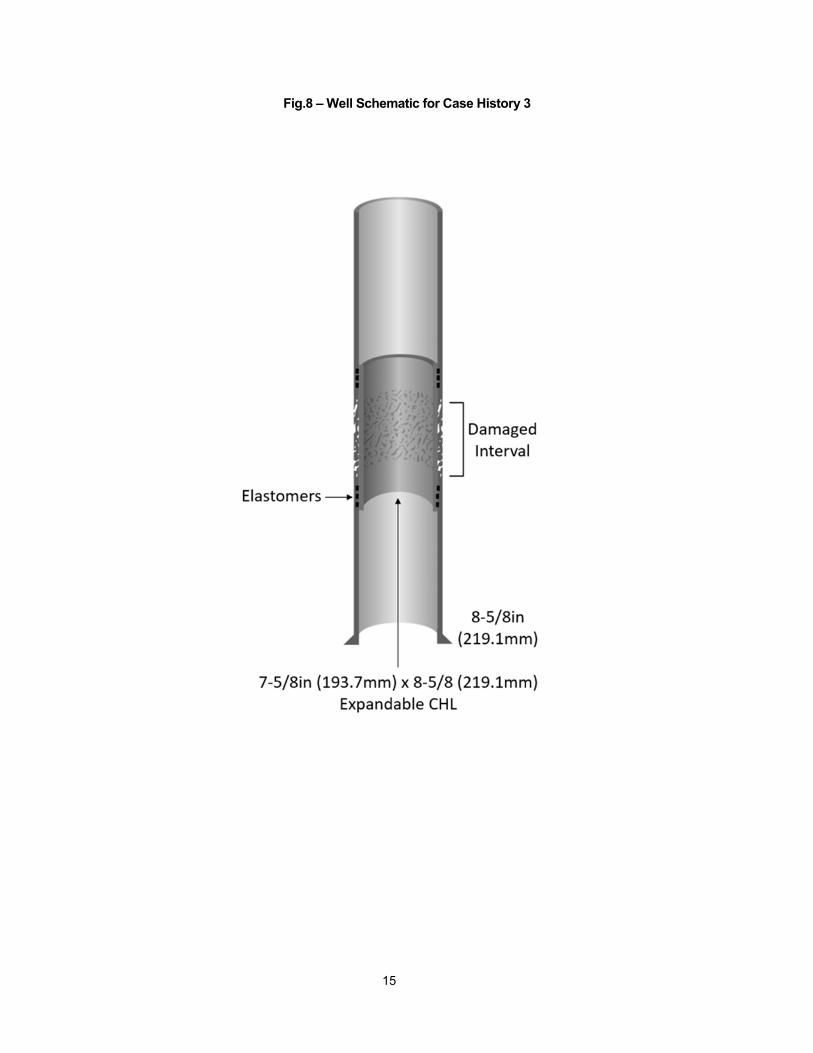
Fig.8 – Well Schematic for Case History 3
15