the use of sustainable materials for quick repair … iu-22_final_report.pdfthe use of sustainable...
TRANSCRIPT

The Use of Sustainable Materials for
Quick Repair of Aging Bridges
Phase II Final Report
PI: Azadeh Parvin, D.Sc.
Associate Professor
Department of Civil Engineering
College of Engineering
Prepared for The University of Toledo University Transportation Center
and the U.S. Department of Transportation
February 2012

1
DISCLAIMER
The contents of this report reflect the views of the authors, who are responsible
for the facts and the accuracy of the information presented herein. This document
is disseminated under the sponsorship of the Department of Transportation
University Transportation Centers Program, in the interest of information
exchange. The U.S. Government assumes no liability for the contents or use
thereof.

2
EXECUTIVE SUMMARY
During the last decade fiber reinforced polymer (FRP) materials have gained wide acceptance for
repair and strengthening of existing infrastructures or to design new infrastructures due to their
desirable properties (high strength to weight ratio, light weight and consequent ease of field
placement, corrosion resistance, durability, and low maintenance cost among others). There is a
need to strengthen the deficient and aging civil infrastructure or new structures that are identified
with certain design flaws against sudden loads including impact, blast, natural disasters, or
increased traffic loads over time. The addition of FRP materials to upgrade the deficiencies or to
strengthen the structural components prior to collapse can save lives and damage to the
infrastructure, and reduces the need for their costly replacement. Furthermore, due to their
desirable properties, the retrofit with the FRP materials provides an excellent replacement for
traditional materials including steel jacket to strengthen the damaged reinforced concrete
structural members that are repairable.
An innovative, reliable, fast, durable, and cost efficient FRP retrofit technique was proposed to
enhance the capacity of bridge components that are in serious need of strengthening due to
deterioration, accidental damage, or an increase in axial load demand. The strengthening
technique involved the use of FRP sheets to wrap the column as an external reinforcement.
Nonlinear finite element analysis (FEA) software program was used to simulate the behavior of
scaled-down concrete bridge column models prior and after fiber composite wrapping retrofit.
The as-built and FRP-retrofitted columns were compared to access the confinement effectiveness
of the retrofit technique necessary to overcome the increase demand in axial load capacity. The
FRP-strengthened column showed considerable improvement in axial load and displacement
capacities as compared to as-built column model. The findings reveal that the FRP strengthening
can be used to restore the original strength of the column that might have been lost due to
possible deterioration, and even to carry the increased traffic load that was never designed for.
Such solution can postpone the costly replacement of the bridge or bridge components while
insuring the safety of the structure. Additionally, the use of fiber reinforced polymers offers an
excellent alternative rehabilitation technique as non-metallic sustainable reinforcement with
considerable savings relative to conventional strengthening methods due to the low maintenance
and life cycle costs.

3
INTRODUCTION
Fiber reinforced polymer (FRP) wrapping of concrete columns is an ideal technique to increase
the strength and ductility of these structural elements (Rochette and Labossiere, 2000; Parvin and
Jamwal, 2006; Ozbakkaloglu and Akin, 2011). In this project, the performance of scaled-down
as-built and FRP-wrapped circular concrete columns have been investigated using ANSYS
nonlinear finite element analysis software program at Ohio Supercomputer Center (ANSYS
2009) to gain insight into the behavior of such columns.
METHODOLOGY
In the following sections the finite element analysis modeling details including the geometry and
reinforcement arrangement of reinforced concrete (RC) column and carbon fiber reinforced
polymer (CFRP)-wrapped RC column, element types, material models, boundary conditions, and
simulation results are discussed.
Geometry and Reinforcement Details
In order to examine the behavior of axially loaded column before and after CFRP-strengthening,
scaled-down finite element models of circular tied columns were developed. The columns had
the dimension of 152 mm × 760 mm. The geometry and reinforcement detail of the finite
element model of the column is shown in Fig. 1. The bottom of the concrete columns was fixed.
The axial load was increased incrementally and applied to the top cross-section of the column on
the steel plate. Figs 2 and 3 show the load and support conditions of the finite element column
models in X-Z and Y-Z directions, respectively, where Z axis is along the axial direction and X
and Y axes are in the plane perpendicular to axial direction of the column. Compression strength
of 28.6 MPa was assigned for the concrete. The longitudinal steel bars and ties had yield
strengths of 483 MPa, and 400 MPa, respectively. Two layers of Tyfo®SCH-41 CFRP sheet
with 0° and 90° fiber orientations with respect to the hoop direction were applied to the CFRP-

4
strengthened column. Although the column in this case is under pure axial load, the fiber
orientations were selected such that the column would be able to withstand axial and flexural
deformations for other loading scenarios. In accordance with the manufacturer’s data sheet,
Tyfo®SCH-41 sheet has a 1 mm thickness per layer with a tensile strength of 986 MPa in the
fiber direction, tensile modulus of 95.8 GPa, and rupture strain of 1%.
Fig. 1. Geometry and reinforcement details of FEA column models

5
Fig. 2. X-Z view of applied axial load and fixed boundary conditions of FEA column models
Fig. 3. Y-Z view of applied axial load and fixed boundary conditions of FEA column models

6
Element Types
To model the concrete, “Solid65” which is a three-dimensional reinforced concrete element
with the ability to crack in tension and crush in compression and options for large plastic
deformation, nonlinear material property, and element death and birth attributes was selected.
The element has eight nodes with three nodal translational degrees of freedom.
The reinforcement bars were modeled by “Link180”, a three-dimensional spar element, which is
a two-node uniaxial tension-compression element with three nodal degrees of freedom and
options for plasticity, creep, swelling, element death and birth, stress stiffening, and large
deflection capabilities. In this study, plasticity and element death and birth options were
implemented.
Carbon fiber reinforced polymer (CFRP) sheets were modeled using “Shell181”, a finite strain
shell element, suitable to model thin to moderately thick shell structures with a membrane
option. Again, this element has features of plasticity, stress stiffening, large deflection, birth and
death, and nonlinear stabilization. Shell181 element is a four-node element possessing six nodal
translational degrees of freedom with the membrane option.
Material Models
Drucker-Prager material model was employed for the concrete. The selected values of cohesion,
angle of internal friction, and dilatancy angle were 8.275 MPa, 28°, and, 0°, respectively.
0°dilatancy angle would result in no increase in material volume when yielding and the flow is
non-associative. The material model replicates core concrete confinement effect.
The reinforcement bars were modeled as an elastic-perfectly plastic material identical in tension
and compression. Perfect bond assumption between the steel bars and concrete was prescribed
by connecting Link180 steel bar element nodes with adjacent Solid65 concrete nodes so that the
two materials share the same nodes.

7
The CFRP composite was characterized as an orthotropic material model with option to
designate the fiber layer orientation. Perfect bond assumption between the CFRP sheets and
concrete was implemented by connecting adjacent nodes of Shell181 and Solid65 element to
share the same nodes.
Mesh Generation and Boundary Conditions
A preliminary finite element analysis was performed on the control column model by varying the
mesh size from course to fine. By comparing preliminary axial force versus displacement
results, a workable mesh density with 15.2 mm element size was selected. To achieve even
stress distributions and to avoid stress concentration, steel plates with 152 mm diameter and 15
mm thickness were added at the locations of loading and support of the columns. Three-
dimensional Solid185 element was used to model the steel plates. Free and fixed boundary
conditions were applied to the top and bottom end of the columns, respectively.
Nonlinear Solutions and Failure Criterion
The total load was applied as series of load steps. Newton Raphson method option in ANSYS
was employed to fulfill the convergence at the end of each load increment within the tolerance
convergence norms. Based on the response of the column for the previous load increment, the
minimum and maximum load increments were controlled and predicted by ANSYS automatic
load stepping. With cracking of the concrete, yielding of the steel bar reinforcement, and post
peak phases, a gradual small load increment was applied to capture the stiffness degradation due
to the crack propagation. Failure of FEA column model was predicted when the analysis stopped
to converge for 0.001 kN load increment using APDL loading code.

8
Finite Element Analysis Results of As-Built and CFRP-Strengthened RC Concrete
Columns
In the finite element analysis results, displacement values were obtained from the center node at
the top of the column. Fig. 4 shows the axial force versus displacement of axially loaded as-
built (control) RC column model. The plateau in the second portion of the curve is an indication
of yielding of steel bars. The peak axial load and deformation were 740 kN and 10.08 mm,
respectively. The deformation profiles of the control column are illustrated in Figs 5 and 6.
Buckling of reinforcement bars was noticeable at the vicinity of the loading plate (Fig. 6).
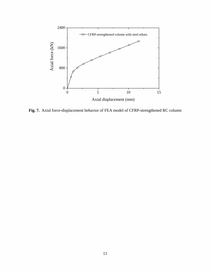
Next, the as-built column is wrapped with two layers of CFRP sheets with 0° and 90° fiber
orientations with respect to the hoop direction, to examine the effect of this strengthening
technique on the column load and deformation capacities. The force versus displacement plot of
the retrofitted column is presented in Fig. 7. The second portion of this bilinear plot
demonstrates when the CFRP sheets become active in confining the concrete column. The
maximum load and deformation were 1,880 kN and 11.82 mm, respectively. The column axial
load capacity had increased 154% as compared to the control counterpart column due to the
additional confinement provided by the CFRP sheets. The axial displacement capacity was also
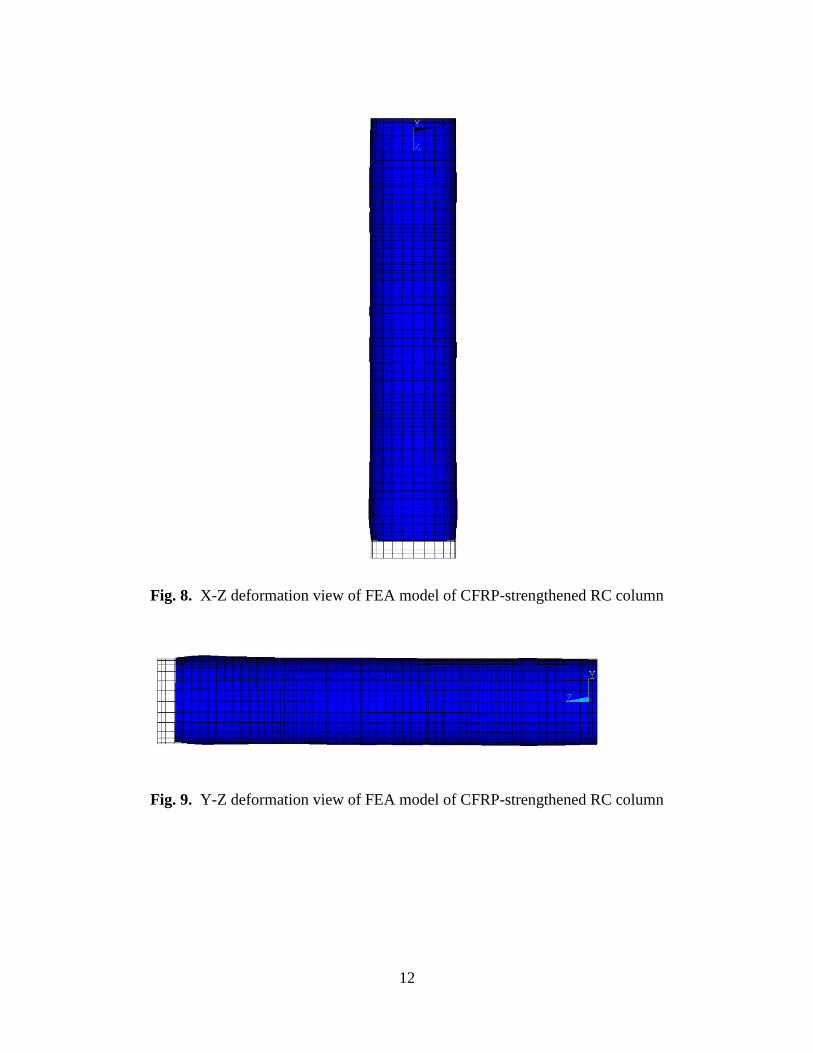
increased by 17% (Fig. 8). X-Z and Y-Z deformation views of FEA model of CFRP-
strengthened RC column are shown in Figs. 9 and 10. No buckling was observed in the
retrofitted column.

9
0 4 8 120
200
400
600
800
Axia
l fo
rce
(kN
)
Axial displacement (mm)
control column with steel rebars
Fig. 4. Axial force-displacement behavior of FEA model of control RC column

10
Fig. 5. X-Z deformation view of FEA model of control RC column
Fig. 6. Y-Z deformation view of FEA model of control RC column
11
0 5 10 150
800
1600
2400
Axia
l fo
rce
(kN
)
Axial displacement (mm)
CFRP-strengthened column with steel rebars
Fig. 7. Axial force-displacement behavior of FEA model of CFRP-strengthened RC column
12
Fig. 8. X-Z deformation view of FEA model of CFRP-strengthened RC column
Fig. 9. Y-Z deformation view of FEA model of CFRP-strengthened RC column

13
0 5 10 150
800
1600
2400
Axia
l fo
rce
(kN
)
Axial displacement (mm)
CFRP-strengthened column with steel rebars
control column with steel rebars
Fig. 10. Comparison of axial force-displacement behavior of FEA models of control and CFRP-
strengthened RC columns
CONCLUSIONS
An innovative, reliable, fast, durable, and cost efficient FRP retrofit technique was proposed to
enhance the capacity of RC columns that are in serious need of strengthening due to
deterioration, accidental damage, or an increase in axial load demand. Nonlinear finite element
analysis provided a great tool to investigate the behavior RC column models before and after
retrofit through simulation. The external upgrade scheme using high strength, light weight,
noncorrosive, durable, and sustainable composite material was able to enhance the capacity of
the RC column. The axial load capacity of the CFRP-strengthened RC column was increased by
more than 1.5 times when two layers of CFRP sheet were wrapped around the RC column. The
CFRP external strengthening also controlled the buckling of the axially loaded RC column. The
finite element analysis findings showed a great promise for the wide use of FRP retrofit
including lateral confinement of the bridge piers to be able to withstand additional axial (gravity)
load generated due to increased load requirements or excessive traffic loads. This retrofit

14
technique is also an excellent venue to repair the older bridge piers that have lost their cover
overtime.
REFERENCES
1. ANSYS (2009), ANSYS, Inc., Canonsburg, PA.
2. Rochette, P., and Labossiere, P. (2000). “Axial testing of rectangular column models
confined with composites.” Journal of Composites for Construction, 4(3), 129-136.
3. Parvin, A., and Jamwal, A. S. (2006). “Performance of externally FRP reinforced columns
for changes in angle and thickness of the wrap and concrete strength.” Composite Structures,
73(4), 451-457.
4. Ozbakkaloglu, T., and Akin, E. (2011). “Behavior of FRP‐confined normal‐ and
high‐strength Concrete under cyclic axial compression.” Journal of Composites for
Construction, doi:http://dx.doi.org/10.1061/(ASCE)CC.1943-5614.0000273