the use of fiber reinforcement in latex modified concrete ... · pdf filethe use of fiber...
TRANSCRIPT

The Use of Fiber Reinforcement in
Latex Modified Concrete Overlay
NCDOT Project 2016-07
FHWA/NC/2016-07
December 2016
Danny Smyl
Armita Mohammadian
Sungwoo Park
Gregory Lucier
Mohammad Pour-Ghaz
Dept. of Civil, Construction and Environmental
Engineering
North Carolina State University

The Use of Fiber Reinforcement in Latex Modified Concrete Overlay
FINAL REPORT
Prepared by:
Danny Smyl
Armita Mohammadian
Sungwoo Park
Gregory Lucier
Mohammad Pour-Ghaz
A report on research sponsored by:
THE NORTH CAROLINA DEPARTMENT OF TRANSPORTATION
April 2017
Technical Report Documentation Page
1. Report No.
FHWA/NC/2016-07
2. Government Accession
No.
3. Recipient’s Catalog No.
4. Title and Subtitle
The Use of Fiber Reinforcement in Latex Modified Concrete
Overlay
5. Report Date
December 23, 2016
6. Performing Organization
Code
7. Author(s)
Danny Smyl; Armita Mohammadian; Sungwoo Park; Gregory
Lucier; Mohammad Pour-Ghaz
8. Performing Organization
Report No.
9. Performing Organization Name and Address
Department of Civil, Construction and Environmental
Engineering
North Carolina State University
10. Work Unit No. (TRAIS)
208 Mann Hall (Main Office)
2501 Stinson Drive
Raleigh NC 27695-7908
11. Contract or Grant No.
12. Sponsoring Agency Name and Address
North Carolina Department of Transportation
Research and Analysis Group
1 South Wilmington Street
Raleigh, North Carolina 27601
13. Type of Report and Period
Covered
Final Report
08/2015 – 12/2016
14. Sponsoring Agency Code
RP-2016-07
Supplementary Notes:
16. Abstract
The requirement to quickly reopen highways in North Carolina has motivated the increased use of
rapid-setting concrete in overlays. The addition of polymer latex to the material has been used to
increase the service life of the overlays. The latex modified very early strength concrete (LMC-
VES), however has been reported to exhibit cracking early on after opening the road to traffic. To
address this, this report investigates the early-age behavior and the use of non-metallic fiber
reinforcement in LMC-VES. A state-of-the-art literature review is provided, an extensive
experimental program is conducted, a review of current construction practice is presented, and
findings and recommendations are reported.
17. Key Words
Concrete Overlay, repair, rehabilitation,
service life, polymer modification
18. Distribution Statement
19. Security Classif. (of this
report)
Unclassified
20. Security Classif. (of this
page)
Unclassified
21. No. of Pages
72
22. Price
Form DOT F 1700.7 (8-72) Reproduction of completed page authorized

4
DISCLAIMER
The contents of this report reflect the views of the author(s) and not necessarily the views
of the University. The author(s) are responsible for the facts and the accuracy of the data
presented herein. The contents do not necessarily reflect the official views or policies of
either the North Carolina Department of Transportation or the Federal Highway
Administration at the time of publication. This report does not constitute a standard,
specification, or regulation.

5
ACKNOWLEDGMENTS
The authors would like to acknowledge the support of the North Carolina Department of
Transportation Office of Research and Development. The technical support provided by
NC State Constructed Facilities Laboratory (CFL) staff, Mr. Johnathan McEntire and Mr.
Jerry Atkinson, is greatly acknowledged. Materials and services were donated by Modified
Concrete Suppliers, LLC; CTS; Forta-Ferro; Wagman, and BASF. All of these generous
contributions are greatly appreciated.

6
EXECUTIVE SUMMARY
Due to the requirement of rapid reopening and resuming traffic in highways, concrete
materials produced with rapid-setting cement are often used by state Departments of
Transportation (DOTs) for patching or overlaying bridge decks. Very often, micronized
latex polymer is added to reduce the ingress of moisture and deicing salts, potentially
increasing the service life of the bridge deck. The use of such rapid-setting materials in
some instances has been noted by various DOTs to exhibit cracking soon after opening the
road to traffic. However, the early-age behavior of this material has not been well studied
in laboratory or construction environments, and the causation of some of the observed
cracking is not well understood. It has been suggested by the North Carolina Department
of Transportation (NCDOT) and others that the use of non-metallic fiber reinforcement
could mitigate cracking in plastic or hardened states.
The current project investigates potential reasons for cracking in deck overlays, and further
studies whether non-metallic fiber reinforcement can be used to reduce crack width in
rapid-set latex modified concrete overlays. A state-of-the-art literature review is provided,
current construction practices are evaluated, and an extensive experimental program is
executed. In the experimental program, tests are conducted to evaluate plastic shrinkage
cracking, restrained shrinkage cracking, cement hydration kinetics, effects of curing
conditions, and the behavior of large-scale restrained shrinkage slabs.
While evaluating current construction practices, some undesirable field processes were
observed that may increase the potential for cracking in plastic and hardened states. These
construction processes included i) uncontrolled spraying of water on unfinished and
finished concrete, ii) ad-hoc addition of water at the volumetric mixer, iii) placing (and
finishing) of fresh concrete over a wetted and finished surface, and iv) excessive vibration
of the bridge deck due to traffic.
Results from the experimental program indicate that, due to the expansive nature of rapid
setting cement used in this research, restrained shrinkage cracking is not the primary cause
of cracking in rapid-setting latex modified concrete overlays. Experimental investigations
also confirmed that plastic shrinkage cracking is not a contributing factor to cracking of
the material since, when proper mixture proportioning and placement processes is used, a
meniscus does not form at the surface of the material. Potential sources of cracking were
concluded to result from i) over-finishing in the plastic state, ii) using non-saturated or non-
rewetted burlap during curing, iii) temperature effects in large geometries due to the high
heat of hydration, iv) settlement cracking during rapid hardening, v) other uncontrolled
construction procedures, and vi) excessive vibration of the bridge deck during or shortly

7
after placement. Since plastic and restrained shrinkage cracking did not occur in the
materials, the use of fiber reinforcement was deemed unnecessary and was not required.
However, the use of fiber reinforcement to mitigate cracking due to settlement, improper
finishing and curing procedures, and temperature effects may be effective but requires
further investigation.

8
TABLE OF CONTENTS
1. Introduction ................................................................................................................ 10
2. Materials and Methods ............................................................................................... 12
2.1 General ................................................................................................................... 12
2.2 Materials ................................................................................................................ 12
2.2.1 Cement ............................................................................................................... 12
2.2.2 Aggregates .......................................................................................................... 13
2.2.3 Latex Emulsion .................................................................................................. 13
2.2.4 Non-Metallic Fiber Reinforcement .................................................................... 13
2.2.5 Retarding Chemical Admixture ......................................................................... 13
3.2.6 Mineral and Chemical Admixtures ................................................................... 14
2.2 Selected Mix Design .......................................................................................... 14
3. Experimental Methods ............................................................................................... 14
3.1 Mixing procedure used for plastic shrinkage and ring test .................................... 14
3.2 Calorimetry ............................................................................................................ 15
3.3 Plastic Shrinkage .................................................................................................... 16
3.4 Restrained shrinkage testing (ring test) .................................................................. 19
3.5 Corrugated restrained shrinkage test ...................................................................... 21
3.6 Large slabs ............................................................................................................. 24
4. Experimental Results and Discussion ........................................................................ 26
4.1 General ................................................................................................................... 26
4.2 Calorimetry ............................................................................................................ 26
4.2.1 Phase 1: Mixing conducted outside the calorimeter ........................................... 26
4.2.2 Phase 2: Mixing within the calorimeter ............................................................. 30
4.3 Plastic Shrinkage .................................................................................................... 33
4.4 Restrained shrinkage testing (ring test) .................................................................. 36
4.5 Corrugated restrained shrinkage test ...................................................................... 38

9
4.6 Large-Slab Testing ................................................................................................. 42
5. Evaluation of current practice .................................................................................... 50
5.1 Weather considerations .......................................................................................... 50
5.2 Evaluation of scarifying and surface preparation .................................................. 50
5.3 Material parameters ............................................................................................... 54
5.4 Construction procedures ........................................................................................ 55
6. Findings and Conclusions .......................................................................................... 59
7. Recommendations ...................................................................................................... 60
8. Technology Transfer Plan .......................................................................................... 61
9. References .................................................................................................................. 62
Appendix A: Literature Review – Mechanisms of cracking in concrete overlays ........... 65
A.1 Plastic Shrinkage .................................................................................................... 65
A.2 Drying Shrinkage ................................................................................................... 67
A.3 Thermal Cracking ................................................................................................... 69
A.4 Settlement Cracking and Cracking from Finishing ................................................ 69

10
1. Introduction
In 2005, the FHWA estimated that $10.5 billion was spent on rehabilitating deteriorated
bridges due to corrosion [2]. Furthermore, associated costs from traffic delays and loss of
productivity are estimated to be ten times this figure [3]. Transportation agencies have
conducted extensive research to mitigate these costs since the 1960’s by improving mix
designs, developing admixtures, and refining construction procedure in concrete bridge
decks and roadways. The majority of these studies aimed to improve the durability of
cementitious materials used in transportation structures and thereby increase safety and
service life.
Latex-modified concrete (LMC) and LMC-Very Early Strength (LMC-VES) concrete
are commonly used by Departments of Transportation (DOTs) in bridge overlays.
Overlays placed over concrete structures and roadways avoid full structural replacement
and have been identified as an effective means of increasing service life of bridge decks
[6]. LMC and LMC-VES materials offer advantages over conventional concrete.
Uncracked LMC has been shown to improve resistance to corrosion and water penetration
[1, 7], skid resistance, abrasion, ride quality, and physical appearance [2]. However, recent
reports nationwide have shown that cracking is common in LMC and LMC-VES overlays.
Cracking in concrete (e.g., in bridge decks) accelerates deterioration by increasing material
hydraulic conductivity and creating paths for corrosive chemicals to penetrate [4].
Traditionally, cracking in concrete bridge decks and roadways is largely attributed to
thermal and shrinkage stresses [5]. Limited research, however, exists that identify the
primary factors contributing to uncontrolled cracking of LMC and LMC-VES, and
effective methods of mitigation of such cracking have not been identified.
LMC-VES has been used by Missouri DOT (MoDOT) and cracking of these overlays
has been reported as a major issue [8]. The cracking of the overlays is attributed by MoDOT
to de-bonding resulting from the absence of a rough substrate surface. To reduce the effect
of de-bonding, hydroblasting of the surface is recommended [8]. Large thickness overlays,
beyond 3 inches, are also identified as a factor contributing to cracking. Therefore,
MoDOT recommends a maximum 3.0 inch thickness for LMC [8]. Based on discussion
with NCDOT, such restriction on the thickness is also suggested in North Carolina. Due to
cracking issues associated with LMC-VES, the use of this material in Missouri is only
recommended for high traffic areas where traffic control is very complicated and short
construction times are mandatory.
A study performed by the Ohio DOT (ODOT) [9] on alternative overlay concrete
materials has shown that LMC and LMC-VES were the only materials within their test
matrix that could obtain enough strength to allow traffic flow within 2 to 4 hours. The
ODOT study showed that LMC-VES and LMC had relatively low shrinkage as compared
to other alternative materials tested, and therefore offered a lower risk of shrinkage

11
cracking [9]. It should be noted, however, that the shrinkage measurements in this study
were performed based on length change measurements and restrained shrinkage cracking
of the materials was not evaluated.
LMC is commonly produced using no-shrink (or low shrinkage) cements which show
expansive behavior similar to Type K cement. This type of LMC was studied by VDOT
[10]. This study was of significant interest to VDOT, as an estimated $2.9 billion is spent
yearly in Virginia on concrete bridge overlays. Standard metrics including slump, air
content, temperature, compressive strength, shrinkage, bond strength, and shrinkage were
tested in this study. Results indicated that LMC produced using low shrinkage cement
resulted in less shrinkage, as per ASTM C157, than LMC with Type I/II cement. This was
to be expected since low shrinkage cements behave similar to Type K cement and show
expansion at early-stages of hydration. All other experimentally-tested properties
compared similarly.
Despite the widespread use of LMC and LMC-VES across the United States, limited
research is available identifying the primary factors contributing to cracking. Methods for
reducing and controlling cracking in these materials are not well explored and little
information is available in the literature. However, it is rather well known that the addition
of fibers to cementitious materials is highly effective at reducing the crack width in plastic
shrinkage cracking [11] and may decrease crack width due to autogenous and drying
shrinkage [12]. In overlays, the reduction in crack width and frequency drastically
decreases hydraulic conductivity of the material, thereby decreasing the amount of
moisture and aggressive chemical agents penetrating into the existing structure.
Very limited research data are available on the use of fiber reinforcement in LMC and
LMC-VES materials. Issa et al. (2007) [13] performed a study on the use of glass fibers in
LMC. To avoid possible complications resulting from mixing LMC with fibers in
volumetric mixers, Issa et al. [13] developed a fiber feeder system for volumetric mixers.
In another study, Kim and Park (2013) [14], determined that the addition of nylon and
polypropylene fibers increased resistance to mechanical microcracking and abrasion
resistance of precast concrete.
While these studies show promising results which may indicate that the addition of
fiber reinforcement may mitigate cracking in LMC, the effects of fiber in LMC on (i)
shrinkage induced cracking in VES material, (ii) restrained shrinkage, (iii) drying
shrinkage, and (iv) dosage to mitigate shrinkage-induced cracking are unknown.
Additional research in these areas is required to improve control of cracking in LMC and
LMC-VES materials using fiber reinforcement. Also much needed is understanding the
reason for cracking of LMC-VES materials as this knowledge will help in selecting the
proper type of fibers to reduce the risk of cracking or crack width. A detailed review of
the underlying mechanisms of cracking in concrete overlays is provided in Appendix A.

12
2. Materials and Methods
2.1 General
This research focused on the behavior of the LMC-VES material currently used in NCDOT
overlays. After a careful review of materials currently used by contractors, the concrete
mix design was proportioned to represent a typical field mixture and was approved by
NCDOT. All material used in this study complied with NCDOT Standard Specifications
for Roads and Structures. The following constituents (with NCDOT material
requirements) generally comprise a typical field mix design:
Cement: High early strength cement (Rapid-Set), 6 bags/yd3, 658 lb/yd3
Coarse aggregate: 78M, NCDOT requirement for LMC-VES overlays.
Fine aggregate: natural river sand.
Latex emulsion: water – micronized latex emulsion, typical dosage of 24.5 gal/yd3,
NCDOT minimum requirement
w/c ratio: (w/c < 0.40), NCDOT requirement
Retarder: Citric acid is commonly used, dosages not generally recorded, although
0.1 – 0.4% (by weight of cement) is commonly accepted. This would correspond
to a dose of 1.3 – 2.6 lb/yd3 in common NCDOT mixes.
2.2 Materials
2.2.1 Cement
CTS Rapid-Set cement was approved for this study by NCDOT as it was the most
commonly used cement used by NCDOT contractors from the information provided. This
cement contains tetracalcium trialuminate sulfate (𝐶4𝐴3𝑆̅) which is the main component in
Type K cement responsible for early age expansion [32]. It should be noted that the amount
of 𝐶4𝐴3𝑆̅ in Rapid-Set cement is significantly lower than that of Type K cement.
Rapid-Set cement hydrates quickly, with an initial set time of approximately 17
minutes. The “rapid-setting” characteristic of this cement results from early-age formation
of ettringite. The rapid formation of ettringite in early age material results in volumetric
expansion, accelerated heat generation, and increased water requirement [32]. The
manufacturer’s recommended water-to-cement (w/c) ratio for this cement is 0.4-0.5.
The volumetric expansion in the early-age cement has led to the popular material
characterization, “no-shrink or low shrinkage cement.” That is, some fraction of volumetric
dilation due to chemical and drying shrinkage is compensated by early-age expansion.
13
Results from [29] show that Type-K cement expands at early ages, but results in net
volumetric shrinkage. However, shrinkage results for concrete containing Rapid-Set
cement are currently unavailable in literature.
2.2.2 Aggregates
Aggregates used in this study complied with NCDOT Standard Specifications for
Roads and Structures. The specifications required that the coarse aggregate use standard
size No. 78M in all mixes. The fine aggregate used here was selected from readily available
natural river sand (FM = 2.63) from a local ready-mix plant.
2.2.3 Latex Emulsion
The latex emulsion used in this study was the most frequently used latex emulsion in
the provided contractor mix design list. BASF Styrofan 1186, an aqueous styrene-
butadiene copolymer dispersion, was selected. The average particle size in the water
emulsion was 0.2 µm with an emulsion total solids content of 48.0%. The minimum
NCDOT requirement for latex emulsion content in LMC mixes is 24.5 (gal/yd3). The use
of latex emulsion > 24.5 (gal/yd3) was not observed in any current NCDOT contractor
mixes.
The purpose of adding the latex emulsion to cement-based materials is to reduce
hydraulic conductivity (permeability). Addition of latex does this by creating an “elastic
membrane” (or continuous phase) throughout the material matrix. Such addition may also
increase flexural strength and abrasion resistance [8]. This is certainly true for hardened
material, however, the effects of latex addition (due to decreased matrix permeability) on
hydration currently not well researched.
2.2.4 Non-Metallic Fiber Reinforcement
0.25 inch nylon fibers and 0.75 inch nylon mechanical fibers were acquired. The fibers
were acquired from Forta Corporation and have a tensile strength of 140 ksi (966 MPa), as
reported by the manufacturer.
2.2.5 Retarding Chemical Admixture
The Rapid-Set cement used in this study loses workability within 17 minutes after
water to cement contact. This has significant implications on placing and finishing of the
fresh material. For this reason, contractors often add citric acid “as needed” to the mix as
a retardering chemical admixture [33]. Citric acid appears to be the most commonly used
retarder in LMC-VES applications, however, no established dosage guideline for this
admixture is available. A general “rule of thumb” is 0.1 – 0.4% addition of citric acid by
the weight of cement. An addition of 2.6 lb/yd3 of citric acid results in a doubling of initial

14
set time of this cement, as reported by the manufacturer. As per the manufacturer, each
0.1% addition of citric acid results in a 5-15% increase in initial set time. While the addition
of citric acid increases the time of set, caution should be exercised in the use of a dosage
higher than 1.0% by the weight of cement which may result in plastic shrinkage cracking
due to an extensive drying period and reducing the early-age compressive strength below
the specific requirement. Overall, the effect of citric acid as a chemical admixture for
Rapid-Set cement addition is not well-understood.
3.2.6 Mineral and Chemical Admixtures
Only citric acid is added as a chemical admixture in this study. No additional chemical
or mineral admixtures were considered.
2.2 Selected Mix Design
Table 1 shows the approved mix design used in this study. Note that citric acid was
added to drying shrinkage and calorimetry specimens.
Table 1: LMC-VES Mix Proportions
Material Weight
(lb/yd3) SG
Fine Aggregate (natural river sand) 1500 2.63
Coarse Aggregate (78M) 1272 2.74
Rapid-Set Cement (CTS) 658 3.10
Water 147 1.00
Latex 209 1.01
Air (5% air) - -
3. Experimental Methods
3.1 Mixing procedure used for plastic shrinkage and ring test
Mixing was conducted in a 0.3 yd3 gas-powered rotary drum mixer. The maximum
rotary speed used during mixing was 30 rpm. Since the non-retarded material becomes
unworkable at a very early age (~17 minutes), immediate removal of the non-retarded
material directly after mixing was required to avoid hardening in the mixer. This method
utilized a maximum mixing time of 4 minutes after addition of cement. The same mixing
procedure was used for the materials containing retarding agent. The steps used in the
mixing procedure are described below:

15
1. Lightly moisten mixer walls (just enough to shine)
2. Remove excess drum water
3. Start drum mixer (30 rpm)
4. Insert fine and coarse aggregate
5. Insert entire latex emulsion
6. Mix for one minute
7. Insert all Rapid-Set cement
8. Insert remaining water
9. Mix for 4 minutes
10. Cast specimens
Step 1 was performed to reduce the adhesion of plastic material to the mixer since
Rapid-set cement is significantly more cohesive than Portland cement. Premixing the
aggregates in step 2 was performed to prevent any aggregate absorption and to increase the
shear stress of the plastic material, thereby increasing the efficiency of cement (and fiber)
intermixing. Immediately after adding the cement, the remaining water was added and
mixing was conducted for 4 minutes.
3.2 Calorimetry
Calorimetry tests were performed to monitor the hydration kinetics of (i) Rapid-Set
cement; (ii) Rapid-Set cement with latex emulsion; (iii) Rapid-Set cement with the addition
of the retarding agent, citric acid; and (iv) Rapid-Set cement with the addition latex and the
retarding agent, citric acid. The testing was conducted in accordance with ASTM C1679-
14. In such a procedure, an automated isothermal calorimeter is used to monitor heat
generated from freshly-prepared paste specimens inside an air-tight glass container. The
heat generated is measured by comparing the heat output difference between cementitious
materials and an inert reference specimen (acid-washed sand).
Eight sets of material were tested using calorimetry, and are summarized in Table
2. Cement paste was mixed using a high-speed dental mixer under vacuum to minimize
entrapped air. The materials were tested in two phases. w/c ratios in phase 1 were selected
to provide a sweep of potential w/c that may be used in overlays, including the w/c ratio
(0.39) for the concrete mix design used in this study. In phase 2, only w/c ratio = 0.39 was
used and material with and without latex addition was tested using two different does of
citric acid. Note that two specimens were cast for each w/c and the dose of latex is
consistent with concrete mix design used in this study (209 lb/yd3).

16
Table 2: Summary of Materials used in Cement Paste Calorimetry Study
w/c Latex Addition Retarder (Citric Acid)
0.32 YES NO
0.39 YES NO
0.39 NO NO
0.42 YES NO
0.39 YES YES, 0.02%
0.39 YES YES, 0.04%
0.39 NO YES, 0.02%
0.39 NO YES, 0.04%
3.3 Plastic Shrinkage
Plastic shrinkage testing was conducted in accordance with procedures in ASTM
C1579-13. The test was designed to determine if plastic shrinkage occurs in material
exposed to elevated temperatures, low RH, and with high wind velocity. To accomplish
this, specimens were placed in an environmentally-controlled chamber at 36°C +/- 1°C
(97°F +/- 2°F) at a RH of 30% +/- 2% for 24 hours. Fans with measured wind speeds of 9
m/s (30 ft/s) were placed directly in front of the specimens, resulting in an measured
evaporation rate of 1.15 (kg/m2.hr), which was greater than the required 1.0 (kg/m2.hr).
The test setup is shown in Figure 1.

17
Figure 1: Experimental testing setup for plastic shrinkage
Two specimens with internal dimensions 160 x 355 x 560 mm were cast as
specified by ASTM. The box molds used were made of ¾ in concrete form plywood.
Welded stainless steel “stress risers” were inserted inside the mold to (i) restrain the
specimen ends and (ii) locally increase the tensile stress at the center of the specimen. The
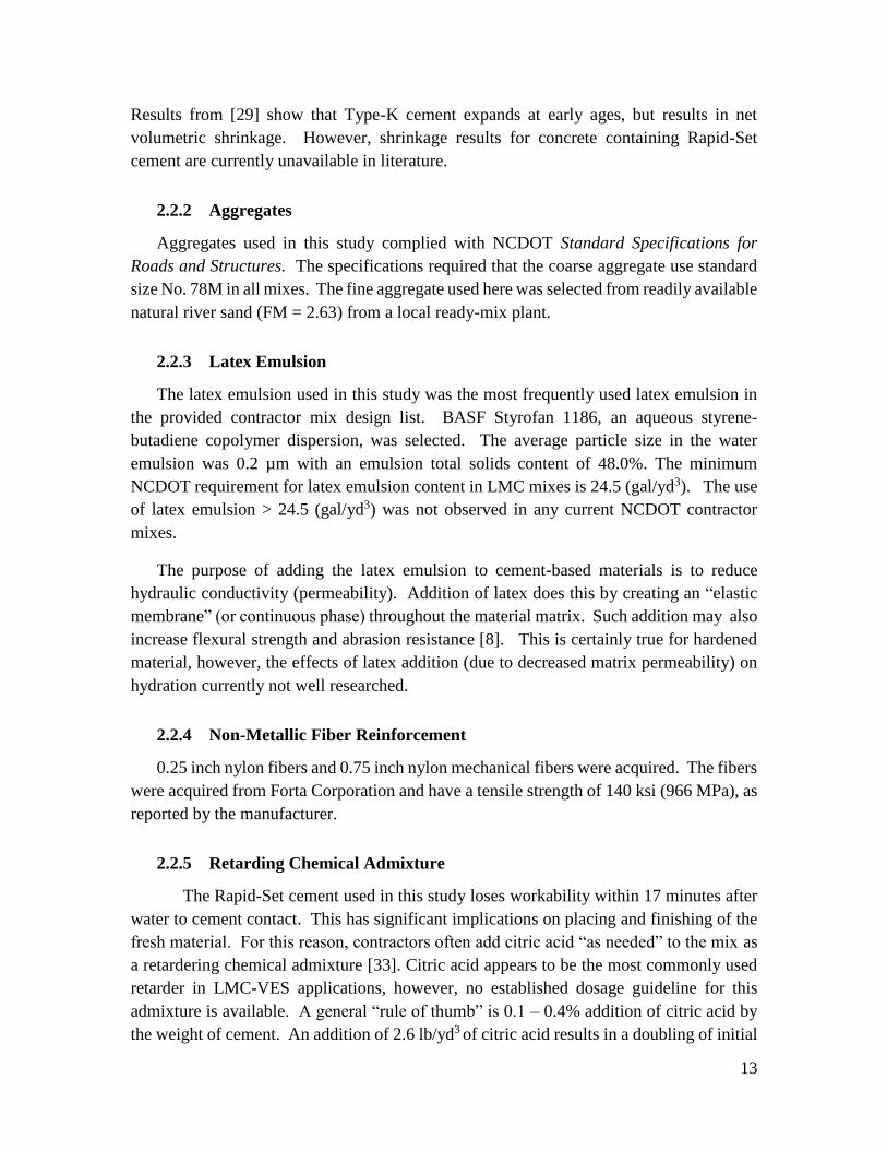
ASTM C1579-13 form drawing is shown in Figure 2. Fresh concrete was placed in the
lightly-oiled forms immediately after mixing. The forms were completely filled with
concrete and vibration was used to consolidate the mix. Careful consideration was taken
to avoid segregation and over-vibrating the specimens during consolidation. The surface
of the materials were finished according to the ASTM standard.
18
Figure 2: ASTM C1579-13 drawing of forms used in plastic shrinkage testing (from
ASTM Standard)
The specimens were finished using the three-strike off method mentioned in ASTM
C1579-13. However, since no retarding agent was used in the rapid-setting material, the
concrete was very stiff at 10 minutes and completely stiff (unworkable) after 17 minutes.
In one specimen (specimen 4), the material was poured approximately 2-3 minutes later
than all other specimens due to difficulty with the mixer and the specimen was over-
finished. The result of over-finishing is discussed in the Results section.
Immediately after finishing the fresh concrete specimens, they were carefully
moved on a rolling cart into the environmental chamber. It is important to note that moving
the quasi-hardened specimens must be done with significant caution to avoid settlement
cracking over the stress riser. With the exception of specimen 4 (the one with the mixer

19
problem), movement of the samples was not a problem. An example of a fresh specimen
inside the chamber is shown in Figure 3.
Figure 3: Plastic shrinkage specimen with fresh concrete
3.4 Restrained shrinkage testing (ring test)
Restrained shrinkage testing was conducted to determine the potential of early age
cracking of a LMC-VES overlay under restrained shrinkage conditions. The material
evaluated in this test was prepared using the mix design described previously in the
Materials Section (mixture with 0.2% citric acid by weight of cement was used). The
ASTM C1591 testing procedure was followed. In this experiment, fresh concrete is cast
around a steel ring with an outer diameter of 13.0 +/- 0.12 inch. Three ring thicknesses
(3/8, 1.0, and 1.5 in) were selected to vary the amount of restraint (degree of restraint).
3/8- and 1.0-inch thick specimens had a height of 6.0 +/- 0.25 inch and the 1.5-inch thick
specimen had a height of 3.0 +/- 0.125 inch. An 18-inch inner diameter cardboard form
with a plastic coated inner wall was selected as the outer ring.
All experiments were carried out for 28 days in an environmental chamber with
controlled temperature of 23.0 + 1.0°C and relative humidity of 50 + 2%. Six samples
consisting of three ring thicknesses (two replicates for each degree of restraint) were tested.
Concrete was mixed according to the mix procedure specified in the Materials Section and

20
consolidated. Immediately after consolidation, four strain gages attached to each steel ring
were connected to an automated strain measurement unit and strain measurements were
taken at 1Hz. Within 10 minutes of connecting to the strain analyzer, saturated burlap was
placed on the top of the specimens. Figure 4 shows the rings specimens throughout the
experimental procedure. Two testing procedures (sealed and drying) were selected and
implemented.
Figure 4: Photos of restrained ring specimens throughout the experimental procedure; (a)
Curing with water-saturated burlap, (b) ring specimens awaiting application of paraffin
wax (Test 2) after removal of cardboard forms, (c) application of paraffin wax to the top
of the specimens, and (d) fully-prepared specimens.
The first condition (sealed) was designed to investigate whether autogenous
shrinkage due to self-desiccation results in cracking. In this set of experiments, the
specimens were completely sealed after curing for 24 hours with wet burlap. The
specimens were sealed by leaving on the cardboard form and sealing the top of the
specimen with paraffin wax for the duration of the 28-day test.
The second set of tests condition simulated early-age drying shrinkage which may
be present in field conditions. In this test, the burlap and cardboard form were removed
after 3 hours. Paraffin wax was then used to seal only the top surface of the specimen

21
ensuring drying occurs only from the outer perimeter of the specimen. A schematic of both
testing procedures are shown below in Figure 5.
Figure 5: Schematic of the restrained shrinkage testing procedures.
3.5 Corrugated restrained shrinkage test
The corrugated restrained shrinkage test was used to evaluate the cracking potential of
concrete. In this test, a prismatic concrete specimen, simulating an overlay, with
dimensions 3 in x 3 in x 36 in was cast on a corrugated steel rail. The steel rail is made of
two steel gear rails welded to a rigid HSS steel beam. During the shrinkage of the concrete,
restraint on the bottom of the specimen is provided by the coupling of the corrugated rail
and the HSS beam (see Figure 6). If materials shrink due to drying and/or self-desiccation,
the corrugated base restrains the material against shrinkage and causes tensile stresses in

22
the material. If the material expands, the base resist the expansion and compressive forces
will develop in the material. Note that the volume above the gear rails is filled with
concrete. A schematic showing the development of forces and the effect of restraint in this
test is shown in Figure 7.
(a)
(b)
Figure 6: (a) Schematic illustration of the corrugated restrained shrinkage/expansion test
simulating a concrete overlay and (b) photographs of the form.

23
Figure 7: Schematic illustration of the corrugated shrinkage/expansion test showing the
resultant forces from shrinkage and expansion of the overlay.
In addition to evaluating the effects of bottom restraint on the cracking behavior of
the overlay, this test also aids in characterizing the cracking potential during consolidation
and finishing. When the fresh material is placed in the specimen mold and consolidated,
there is potential for settlement cracking due to the uneven surface of the restraint. This
can be especially important when the material is rapidly stiffening [5], as is the case with
the material tested in this study. Here, we evaluate cracking potential during vibratory
consolidation and finishing, which will be further discussed in the results section.
24
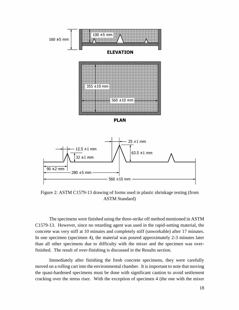
3.6 Large slabs
Four 96in x 24in x 3in specimens were cast. Each specimen had a corrugated
concrete base slab with the thickness of 4in and a 3in bonded overlay on the top of concrete
slab. Figures 8 and 9 show a schematic drawing and photograph of the slab base,
respectively.
Figure 8: Schematic illustration of the bonded LMC overlay on a base of concrete slab.
Figure 9: Corrugated concrete base layer simulating a surface-roughened pavement.
The mix design for the concrete slab (corrugated base) is summarized in Table 3.
The base layer was designed to simulate a typical ordinary Portland Cement-based concrete
pavement. The reinforcement ratio selected was approximately 0.75%.
25
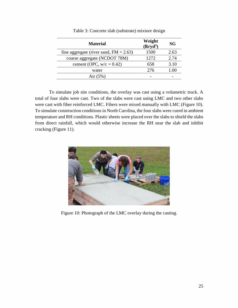
Table 3: Concrete slab (substrate) mixture design
Material Weight
(lb/yd3) SG
fine aggregate (river sand, FM = 2.63) 1500 2.63
coarse aggregate (NCDOT 78M) 1272 2.74
cement (OPC, w/c = 0.42) 658 3.10
water 276 1.00
Air (5%) - -
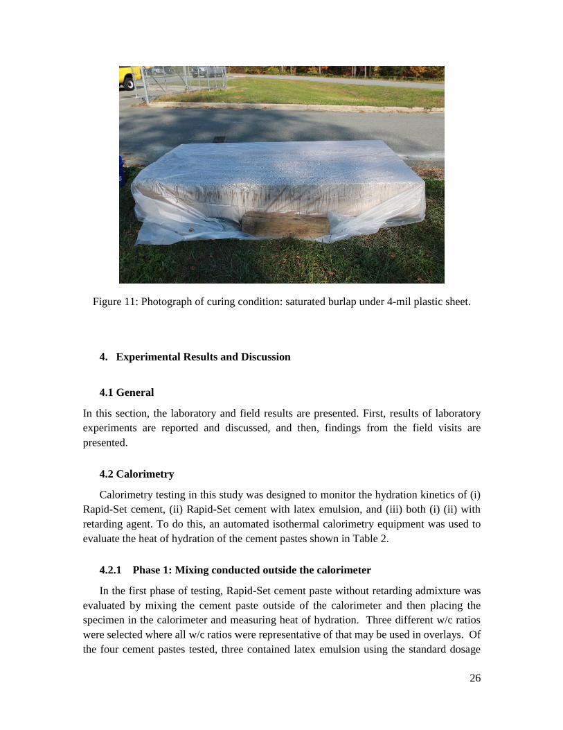
To simulate job site conditions, the overlay was cast using a volumetric truck. A
total of four slabs were cast. Two of the slabs were cast using LMC and two other slabs
were cast with fiber reinforced LMC. Fibers were mixed manually with LMC (Figure 10).
To simulate construction conditions in North Carolina, the four slabs were cured in ambient
temperature and RH conditions. Plastic sheets were placed over the slabs to shield the slabs
from direct rainfall, which would otherwise increase the RH near the slab and inhibit
cracking (Figure 11).
Figure 10: Photograph of the LMC overlay during the casting.
26
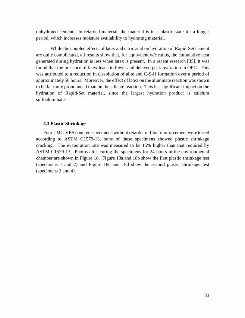
Figure 11: Photograph of curing condition: saturated burlap under 4-mil plastic sheet.
4. Experimental Results and Discussion
4.1 General
In this section, the laboratory and field results are presented. First, results of laboratory
experiments are reported and discussed, and then, findings from the field visits are
presented.
4.2 Calorimetry
Calorimetry testing in this study was designed to monitor the hydration kinetics of (i)
Rapid-Set cement, (ii) Rapid-Set cement with latex emulsion, and (iii) both (i) (ii) with
retarding agent. To do this, an automated isothermal calorimetry equipment was used to
evaluate the heat of hydration of the cement pastes shown in Table 2.
4.2.1 Phase 1: Mixing conducted outside the calorimeter
In the first phase of testing, Rapid-Set cement paste without retarding admixture was
evaluated by mixing the cement paste outside of the calorimeter and then placing the
specimen in the calorimeter and measuring heat of hydration. Three different w/c ratios
were selected where all w/c ratios were representative of that may be used in overlays. Of
the four cement pastes tested, three contained latex emulsion using the standard dosage

27
(equivalent to the minimum NCDOT latex emulsion dose of 24.5 gal/yd3). These latex-
modified pastes (LMP) had w/c ratios of 0.32, 0.39, and 0.42. The final paste was the
control paste, with a w/c = 0.39, containing no latex emulsion. Results of heat flow up to
72 hours in this phase of calorimetry testing are shown in Figure 12. The results are
compared with results of ordinary Portland cement (OPC) without latex emulsion using
w/c ratios of 0.42 and 0.32 for reference. Note that the results report heat flow (rate of heat
generation) normalized to the mass of the cement paste (W/g).
Figure 12: Heat flow measurements for the first 72 hours measured using isothermal
calorimetry. Mixtures include latex modified paste (LMP), Rapid-Set cement, and ordinary
Portland cement (OPC) paste.
Results from the first phase of calorimetry testing show rapid heat development in
Rapid-Set cement pastes. The majority of heat generation in paste containing Rapid-Set
cement occurs in approximately the first four hours after mixing. When hydration kinetics
of different LMP w/c ratios are compared for 72 hours, there is no observable effect on the
rate or evolution of heat development in the Rapid-Set materials tested. Calorimetry results
of paste containing Rapid-Set cement significantly contrast results for OPC paste – in OPC,
at low w/c ratio, the w/c ratio significantly affects the rate of heat generated and the overall
heat evolution of the cement pastes. Moreover, in OPC the peak heat flow occurs 3 – 5
times later than in the Rapid-Set material.

28
Since no distinct differences were apparent for 72-hour results in the LMPs and
Rapid-Set control paste, the heat evolution needed to be viewed at a shorter time span. The
heat flow results for the first 6 hr for LMP and Rapid-Set control pastes are shown in Figure
13.
Figure 13: Heat flow measurements for the first 72 hours measured using isothermal
calorimetry. Mixtures include latex modified paste (LMP) and Rapid-Set cement.
The results in Figure 13 show similar heat evolution for all LMP w/c ratios. There
is a clear time shift in the maximum heat generated between the LMPs and the Rapid-Set
cement without latex emulsion. Moreover, results indicate that the addition of latex also
slightly reduces the peak heat flow, which is also attributed to the reduction in water
availability or coating of cement particles with emulsion.
The heat release from Rapid-Set cement peaks and decays quickly. The calorimetry
results show that the majority of the heat evolution (hydration) occurs in the first 4 hours
in the non-retarded material. The total amount of heat generated, however, is not shown
in Figures 13 or 14. To make this comparison, Figure 14 shows the cumulative heat
generated (normalized to the mass of cement paste, J/g) in LMP, Rapid-Set cement paste,
and OPC pastes.

29
Figure 14: Cumulative heat generated in latex modified paste (LMP), Rapid-Set cement,
and ordinary Portland cement (OPC) paste.
Calorimetry results reporting the cumulative heat generated in Figure 14 show
strong dependence on (i) w/c ratio, (ii) addition of latex, and (iii) cement type. The obvious
differences between OPC and Rapid-Set cement are the rapid heat generated in the Rapid-
Set cement and the magnitude of total heat generated between the two materials.
In Rapid-Set cement, the process of hydration occurs at a much faster rate than
observed in OPC. Water availability is further decreased in the hardening system with the
addition of latex (formation of the latex membrane) and with reduction of the w/c ratio.
Indeed, the cumulative amount of heat generated during hydration is decreased in cement
paste containing Rapid-Set cement with lower w/c ratios. Moreover, the addition of latex
resulted in a ~50% reduction in 72-hour heat generation in Rapid-Setting cement paste (w/c
= 0.39) when latex was added. The addition of latex to non-retarded Rapid-Setting cement
paste (i) retards hydration and (ii) decreases water availability to hydrating cement, thereby
reducing the degree of hydration throughout the hydration process.
At 72 hours, the cumulative heat generated by OPC is approximately 2.5 – 3 times the
magnitude of LMP and Rapid-Set cement. This is, in part, an artifact of not capturing the
initial 5-9 minutes of hydration, which was required in preparing the calorimetry
specimens. Nonetheless, the effect of w/c ratio has a substantial impact on cumulative heat
generated in cement pastes. This is shown for LMPs, where increasing the w/c ratio from

30
0.32 to 0.42 doubled the cumulative heat generated. According to the manufacturer, the
Rapid Set material may require w/c ratios up to 0.50 to fully hydrate, depending on the
exact chemical constitution. Due to the reduction of local water availability, this
requirement may be higher with the addition of latex to the system.
4.2.2 Phase 2: Mixing within the calorimeter
Phase 2 of calorimetry testing differs from Phase 1 testing in that (i) mixing was conducted
inside the calorimeter and (ii) results are reported for cement paste with retarder (citric
acid). Mixing was conducted inside the calorimeter to measure very early-age heat of
hydration. This was not possible with the techniques used in Phase 1 since in Phase 1
mixing was performed outside of calorimeter and some of the heat of hydration was
released during mixing. Heat flow for the first 72 hours of hydration is reported for non-
retarded and retarded materials in Figure 15a and 15b, respectively.
Figure 15: Heat release during the first 72 hours measured using isothermal calorimeter
with an internal mixing procedure. Mixtures include latex modified paste (LMP), Rapid-
Set cement, and ordinary Portland cement (OPC) paste; (a) non-retarded material and (b)
material retarded with 0.2% citric acid (by weight of cement).
Heat flow results shown in Figure 15a show a similar trend to the calorimetry
results reported from the external mixing procedure. Differences in curve shape and the

31
magnitude of heat flow shown in results between the two methods are due to the mixing
procedures. In general, all results for the non-retarded materials show rapid heat generation
after water and latex are added – indicating rapid hydration of the cement pastes. The peak
heat of hydration in these pastes occurs approximately 10-14 hours before that of OPC.
Cement pastes retarded using 0.2% citric acid are shown to have a reduction in peak
heat of hydration and significantly different behavior than non-retarded cement paste.
Unlike the non-retarded pastes, the retarded materials with a w/c ratio greater than 0.32
show an initial spike in heat generated (due to hydrolysis of cement compounds) followed
by a short dormancy period (approximately 2-6 hours) and rapid generation of hydration
products. In this range of w/c ratios, the peak heat of hydration is shifted approximately
10 hours due to the addition of citric acid, which is comparable to the peak heat of hydration
for OPC with a 0.32 w/c ratio. In contrast, the retarded material with a 0.32 w/c ratio
showed a large initial peak in heat generated and a very short dormant period. Similar to
hydration kinetics of OPC, the restriction of water at low w/c ratios leads to rapid formation
of hydration products followed by deceleration of the reaction.
The results for the retarded material also show a noticeable increase in the peak
heat of hydration for the material without latex. To more closely evaluate this behavior,
which occurs around 12 hours, 24-hour calorimetry results are reported for the retarded
material in Figure 16.

32
Figure 16: Heat release during the first 24 hours measured using isothermal calorimeter
with an internal mixing procedure. Mixtures include latex modified paste (LMP) and
Rapid-Set cement.
The 24-hour calorimetry results clearly show that there is a coupled effect of citric
acid and latex. While the peak heat of hydration occurs at roughly the same time for the
pastes with a w/c ratio of 0.39, the peak heat generated by the material without latex is over
twice the magnitude of the material with latex. This indicates that latex may reduce the
heat of hydration in the system. In order to better understand the effect of latex in the
retarded paste, Figure 17 shows 72-hour results reporting the cumulative heat generated in
the retarded cement pastes. Note that the results for the cumulative heat generated in non-
retarded pastes are similar to results from the external mixing procedure and are therefore
not reported.
Figure 17: Cumulative heat generated using an internal mixing procedure in latex modified
paste (LMP) and Rapid-Set cement.
Overall the total amount of heat generated in the retarded material is about 1.5 times
larger than in non-retarded materials. This observation emphasizes the role of early-age
hydration in LMC-VES materials. In the non-retarded material, especially in materials
containing latex, the microstructure rapidly hardens and decreases moisture availability to
33
unhydrated cement. In retarded material, the material is in a plastic state for a longer
period, which increases moisture availability to hydrating material.
While the coupled effects of latex and citric acid on hydration of Rapid-Set cement
are quite complicated, all results show that, for equivalent w/c ratios, the cumulative heat
generated during hydration is less when latex is present. In a recent research [35], it was
found that the presence of latex leads to lower and delayed peak hydration in OPC. This
was attributed to a reduction in dissolution of alite and C-S-H formation over a period of
approximately 50 hours. Moreover, the effect of latex on the aluminate reaction was shown
to be far more pronounced than on the silicate reaction. This has significant impact on the
hydration of Rapid-Set material, since the largest hydration product is calcium
sulfoaluminate.
4.3 Plastic Shrinkage
Four LMC-VES concrete specimens without retarder or fiber reinforcement were tested
according to ASTM C1579-13, none of these specimens showed plastic shrinkage
cracking. The evaporation rate was measured to be 15% higher than that required by
ASTM C1579-13. Photos after curing the specimens for 24 hours in the environmental
chamber are shown in Figure 18. Figure 18a and 18b show the first plastic shrinkage test
(specimens 1 and 2) and Figure 18c and 18d show the second plastic shrinkage test
(specimens 3 and 4).

34
Figure 18: Photograph of plastic shrinkage of LMC-VES concrete specimens without
retarding agent or fiber reinforcement after 24 hours; (a,b) results from the first test,
specimens 1 and 2; and (b,c) results from the second test.
No plastic shrinkage cracking is observable in specimens shown in Figure 18 (a-d).
In Figure 18d, one crack can be observed; however, this crack is perpendicular to the stress
riser and close inspections showed that this crack is very likely due to finishing and is
limited to the immediate surface (the specimen was cast only a few minutes before the
initial set, 15 minutes). Moreover, three cracks near the stress riser are observed in the
same specimen. Cracking due to over finishing and settlement are shown in with higher
contrast with Gaussian noise reduction using image analysis software (ImageJ) in Figure
19.

35
Figure 19: Photograph of the specimen with shallow surface cracking due over-finishing
(same specimen as Figure 18d).
The absence of plastic shrinkage cracking in the specimens tested is largely due to
the rapid hardening of the concrete. This prevented the formation of surface menisci and
therefore minimal tensile stress develops on the surface of the fresh material. However,
the rapid hardening led to significantly decreased workability which made finishing
difficult and increased the potential for surface cracking due to finishing. To overcome the
decreased workability in the field, retarding agent (citric acid) is often used.
The addition of citric acid may increase the potential for plastic shrinkage cracking,
especially if the concrete is over retarded [34]. Furthermore, over retarding LMC-VES
overlays would likely result in contractors missing early-age strength (3-hour)
requirements. The commonly used dose of citric acid in VES mixes ranges from 1.3 – 2.6
lb/yd3. An addition of 2.6 lb/yd3 results in doubling the initial set time of Rapid-Set cement,
as reported by the manufacturer. As a rule of thumb, each 0.1% addition of citric acid
results in a 5-15% (1-3 minutes) increase in initial set time. It follows that lower doses of
citric acid would result in a decrease in potential for plastic shrinkage cracking, and that
special attention to initial set requirements and field addition of citric acid during mixing
be considered.

36
4.4 Restrained shrinkage testing (ring test)
Restrained shrinkage testing is included to determine the potential of LMC-VES
overlay materials for early-age cracking in restrained conditions. Results from two sets of
experiments, each consisting of a total of six ring tests with three ring thicknesses, are
discussed in this section. To reduce environmental noise due to temperature fluctuations
in the environmental chamber, the strain readings of each ring were calibrated to
temperature. The strain due to temperature fluctuations, 𝜀𝑇, was then removed from the
data using the temperature fluctuation history.
Results for 28-day autogenous restrained shrinkage testing indicate that no cracking
or compressive strains were measured for any ring thickness, therefore no autogenous
shrinkage cracking results are reported. This indicates that, for the self-desiccation test,
the material expansion was greater than autogenous shrinkage – resulting in net expansion.
Such a result is expected for this material, which is “low-shrinkage” and behaves similar
to Type K cement.
Results for Test 2 are shown in Figure 20, which are averages of each ring’s strain
gages. Test 2 is designed to be a “worst case scenario,” since drying started only three
hours after the saturated burlap was removed (ASTM 1591C requires 24 hours of wet
burlap curing). Some drying shrinkage is seen at approximately 1-2 days in all the
specimens, except one specimen with a 1.5 in thick ring. Despite this, shrinkage strains
were not high enough to crack the specimens. As a reference, ring strains above
approximately 150 με, 60 με, and 20 με would be expected to crack the specimens with 3/8
in (ASTM), 1.0 in, and 1.5 in thick steel rings, respectively.

37
Figure 20: Results of drying sealed restrained shrinkage test over 28 days. Plotted are strain
at the inner surface of the steel rings with three sizes of steel ring thickness against time
for six specimens.
From the strain measurements shown in Figure 20, the concrete stress (𝜎𝑐) may also be
computed using
𝜎𝑐 = −𝜀𝑠𝑡(𝑡)𝐸𝑠𝑅𝑜𝑠
2 −𝑅𝑖𝑠2
2𝑅𝑜𝑠2
𝑅𝑜𝑠2 +𝑅𝑜𝑐
2
𝑅𝑜𝑐2 −𝑅𝑜𝑠
2 Eq. 1
where 𝐸𝑠 is the elastic modulus of steel and 𝑅𝑜𝑐is the inner radius of the concrete ring.
Using Eq. 1, the stress history of each drying ring is shown in Figure 21. Note that the
results from the ring that did not register compressive stress on the steel ring (orange line)
is omitted from these results.

38
Figure 21: Results of drying restrained shrinkage test over 28 days. Plotted for the six
specimens are the maximum concrete stress for the three ring sizes against time.
In Figure 21, it is confirmed that stress levels from the restrained drying shrinkage
test did not reach levels high enough to generate cracking. Moreover, the concrete stress
levels remain relatively stable after 1-2 days, indicating further development of tensile
stresses will be minimal. Therefore, the addition of fiber reinforcement to LMC-VES
material will not improve performance in drying conditions.
4.5 Corrugated restrained shrinkage test
In this section, we report the findings of the corrugated restrained shrinkage test.
The purpose of the test was to evaluate the cracking potential of a simulated overlay using
the specimen described in Section 3.5. To do this, we cast three specimens using the
approved mix design specified in the Materials Section. The specimens were consolidated
using vibration and finished using minimal strokes with a trowel. A photograph of a
finished specimen without cracking in the plastic state is shown in Figure 22. In each test,
the specimens were placed in an environmental chamber for 48 hours at 90°F and 20% RH,
simulating a severe condition with high susceptibility to plastic and drying shrinkage
cracking [10].

39
Figure 22: Photograph of a LMC-VES cast on a corrugated steel base.
Three curing conditions were selected in this test. These conditions are presented in the
enumeration below.
1) Curing with initially saturated burlap under 4 mil plastic sheet.
2) Curing with initially saturated burlap, no plastic sheet applied.
3) Curing without burlap.
These conditions were selected as a result of numerous contractors reporting that the
saturation of burlap has a significant impact on the surface cracking behavior of LMC-
VEC materials. Condition (a) was chosen to simulate the NCDOT requirement for curing
LMC-VES overlays. Condition (b) tests the effects of rapidly desaturation of the burlap.
Condition (c) would generally be considered the “worst case scenario.” Condition (b) is
shown in Figure 23 for visualization.
Figure 23: Photograph of curing condition (b): Curing with initially saturated burlap, no
plastic sheet applied.
40
It was noted that in curing conditions (a) the material was visibly desaturated within
45 minutes. However, condition (b) resulted in desaturation of the burlap after 20 minutes
of placement. The tests resulted in cracking in specimens with curing conditions (b) and
(c). Curing condition (a) did not result in cracking.
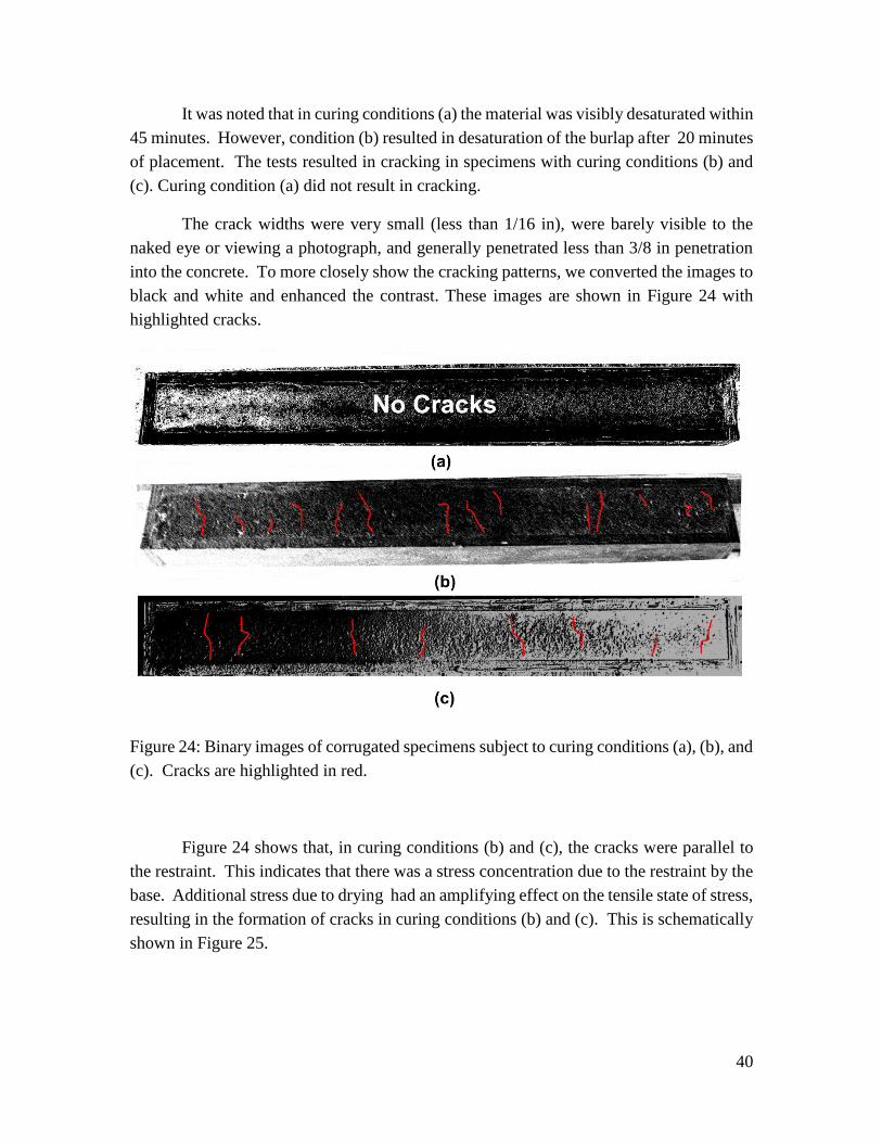
The crack widths were very small (less than 1/16 in), were barely visible to the
naked eye or viewing a photograph, and generally penetrated less than 3/8 in penetration
into the concrete. To more closely show the cracking patterns, we converted the images to
black and white and enhanced the contrast. These images are shown in Figure 24 with
highlighted cracks.
Figure 24: Binary images of corrugated specimens subject to curing conditions (a), (b), and
(c). Cracks are highlighted in red.
Figure 24 shows that, in curing conditions (b) and (c), the cracks were parallel to
the restraint. This indicates that there was a stress concentration due to the restraint by the
base. Additional stress due to drying had an amplifying effect on the tensile state of stress,
resulting in the formation of cracks in curing conditions (b) and (c). This is schematically
shown in Figure 25.

41
Figure 25: Schematic illustration showing the effect of evaporation on crack formation of
the simulated overlay material. Condition (a) no evaporation and condition (b) with surface
evaporation.
The results presented in this section indicate that cracking did not occur when the
NCDOT curing specifications were followed. Moreover, it was found that when the burlap
was allowed to desaturate, the material had more cracks than in a pure drying condition.
This observation resulted from the rapid removal of water, via wicking by the dry burlap,
from the surface of the material. The removal of surface water from concrete in the plastic
state amplified the tensile stress concentrations parallel to the restraint.
42
4.6 Large-Slab Testing
The purpose of the large-slab test was to evaluate the cracking potential of LMC
overlay using large-scale slabs since thermal effects can potentially contribute to cracking.
To do this, four 96in x 24in x 7in specimens were built. Each specimen had a corrugated
concrete base slab and a bonded LMC overlay. The concrete slab simulated a surface-
roughened pavement and had a thickness of 4 in. These bases were cast using the mix
design reported in Table 1. The LMC overlay with the thickness of 3 in was cast on the
top of the concrete base. NCDOT’s LMC mix for I-85 was used to cast overlays. To
simulate job site conditions, the overlay was cast using a volumetric truck. The
compressive strength of the LMC mix was measured after 12 hours, 18 hours, 2 days, 7
days, 14 days, and 28 days. Table 4 presents compressive strength of LMC mix. Note that
the cylinders tested at 12 hours were taken to the laboratory from the field on the evening
of casting and stored overnight inside the warm laboratory. Other cylinders were left in
the field until several hours prior to testing.
Table 4: Compressive strength of LMC mix
Age No. of Samples Strength (psi) Average Strength (psi)
12 hr. 3
6350
6063 6010
5830
18 hr. 3
5529
5712 5720
5887
2 days 3
6580
6685 6616
6860
7 days 2 8097 8108
8118
14 days 2 8575 8503
8430
28 days 3
8367
8609 8901
8558
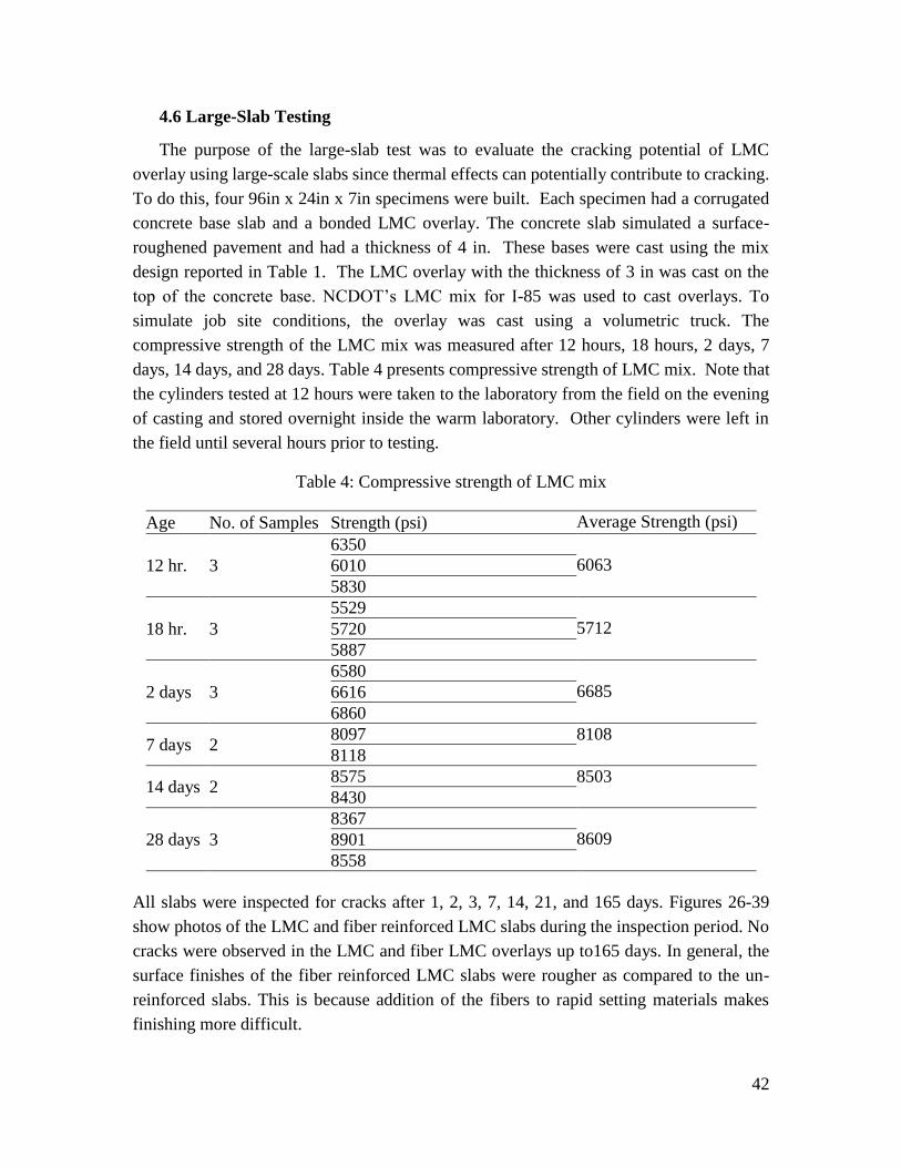
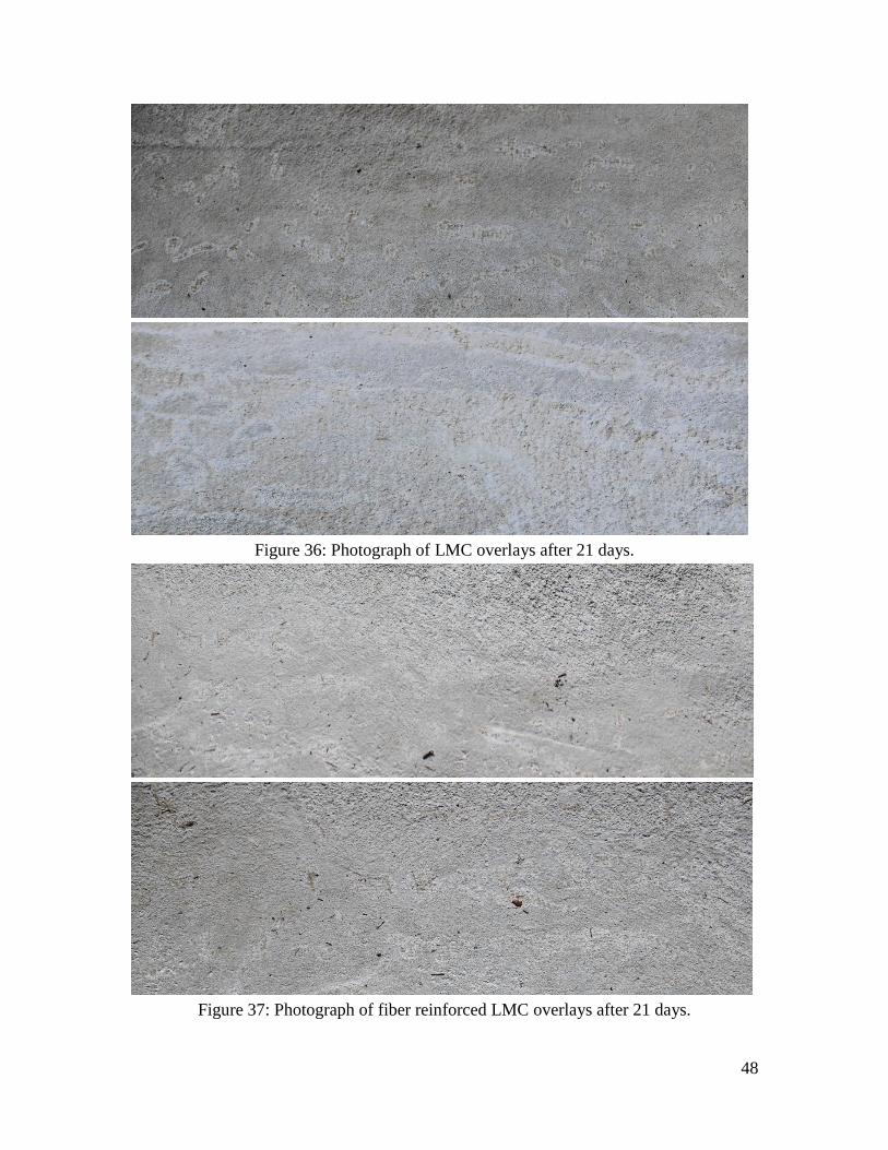
All slabs were inspected for cracks after 1, 2, 3, 7, 14, 21, and 165 days. Figures 26-39
show photos of the LMC and fiber reinforced LMC slabs during the inspection period. No
cracks were observed in the LMC and fiber LMC overlays up to165 days. In general, the
surface finishes of the fiber reinforced LMC slabs were rougher as compared to the un-
reinforced slabs. This is because addition of the fibers to rapid setting materials makes
finishing more difficult.

43
Figure 26: Photograph of LMC overlays after 1 day.
Figure 27: Photograph of fiber reinforced LMC overlays after 1 day.

44
Figure 28: Photograph of LMC overlays after 2 days.
Figure 29: Photograph of fiber reinforced LMC overlays after 2 days.

45
Figure 30: Photograph of LMC overlays after 3 days.
Figure 31: Photograph of fiber reinforced LMC overlays after 3 days.

46
Figure 32: Photograph of LMC overlays after 7 days.
Figure 33: Photograph of fiber reinforced LMC overlays after 7 days.

47
Figure 34: Photograph of LMC overlays after 14 days.
Figure 35: Photograph of fiber reinforced LMC overlays after 14 days.
48
Figure 36: Photograph of LMC overlays after 21 days.
Figure 37: Photograph of fiber reinforced LMC overlays after 21 days.

49
Figure 38: Photograph of LMC overlays after 165 days.
Figure 39: Photograph of fiber reinforced LMC overlays after 165 days.

50
5. Evaluation of current practice
In this section, current construction techniques and materials are discussed. The aim is to
propose recommendations to reduce the risk of cracking and to increase the durability of
LMC and LMC-VES overlays in North Carolina. In the period of study, no overlay
construction with LMC-VES made with rapid-set materials was conducted in North
Carolina. However, LMC (OPC) bridge deck-overlays in the Raleigh area were available
for observation during construction. In this report, we focus on material considerations for
the Dec 21, 2015 bridge deck overlay pour over Gorman Street on Highway 40.
5.1 Weather considerations
On December 21, 2015, the average temperature was measured at 43 degrees
Fahrenheit with an average relative humidity (RH) of 70%. The high RH conditions are,
in general, favorable for a concrete pour and would result in a reduced risk of plastic
shrinkage cracking relative to a hot and windy North Carolina summer day. The low
temperature did not result in low RH, however, set time was expected to be delayed.
Therefore, there was still risk of plastic shrinkage cracking and proper curing procedures
were required.
5.2 Evaluation of scarifying and surface preparation
To increase the bond of the overlay to the bridge deck, the existing concrete was
scarified. Generally, this is done using mechanical or hydraulic (hydro-demolition) means.
NCDOT requires that scarification consists of the following:
“Hydro-demolition shall consist of the removal of the deck surface by means of
high pressure water blasting which will remove concrete, oil, dirt, concrete laitance and
rust from the exposed reinforcing bars by direct impact, pressurization of micro and
macro cracks and cavitation produced by jet instability.” –NCDOT Guidelines for
Managing Hydro-demolition Water
While on the bridge deck, the researchers took several photographs of the scarified
bridge deck. In particular, the researchers were interested in the uniformity (depth and
pattern) of the scarification and the removal of dust, organic particles, and corrosion of
existing reinforcement. Several photos of representative scarified areas are shown in
Figures 40 – 43.

51
Figure 40: Photograph of the north end of the scarified bridge.
Figure 41: Photograph of scarification directly above the bridge mid span.

52
Figure 42: Photograph of scarification in the pour-site (quarter span).
Figure 43: Photograph of scarification on bridge opposite of the pour site.

53
Overall, the depth and distribution of scarification was relatively uniform across
both spans of the Gorman Street Bridge. Several isolated areas had substantial debris
(could be removed by hand) from the hydro-demolition, including areas where concrete
was about to be poured. Some corrosion was visible on exposed reinforcement, by visual
inspection the corrosion appeared to have occurred over the last 48 hours.
Several areas of ponded water with debris were visible in the pouring area (see
Figure 44). NCDOT requires that the area be cleaned 48 hours prior to pouring and the
scarified area be saturated 2 hours before pouring. The removal of excess water is generally
done by an NCDOT approved vacuum apparatus. However, there appeared to be residual
surface water and debris in isolated regions of the pouring area. Excess moisture and debris
can be expected to lower the durability and bond strength of the overlay, and could
potentially contribute to unexpected cracking.
Figure 44: representative area with residual water and debris.
54
5.3 Material parameters
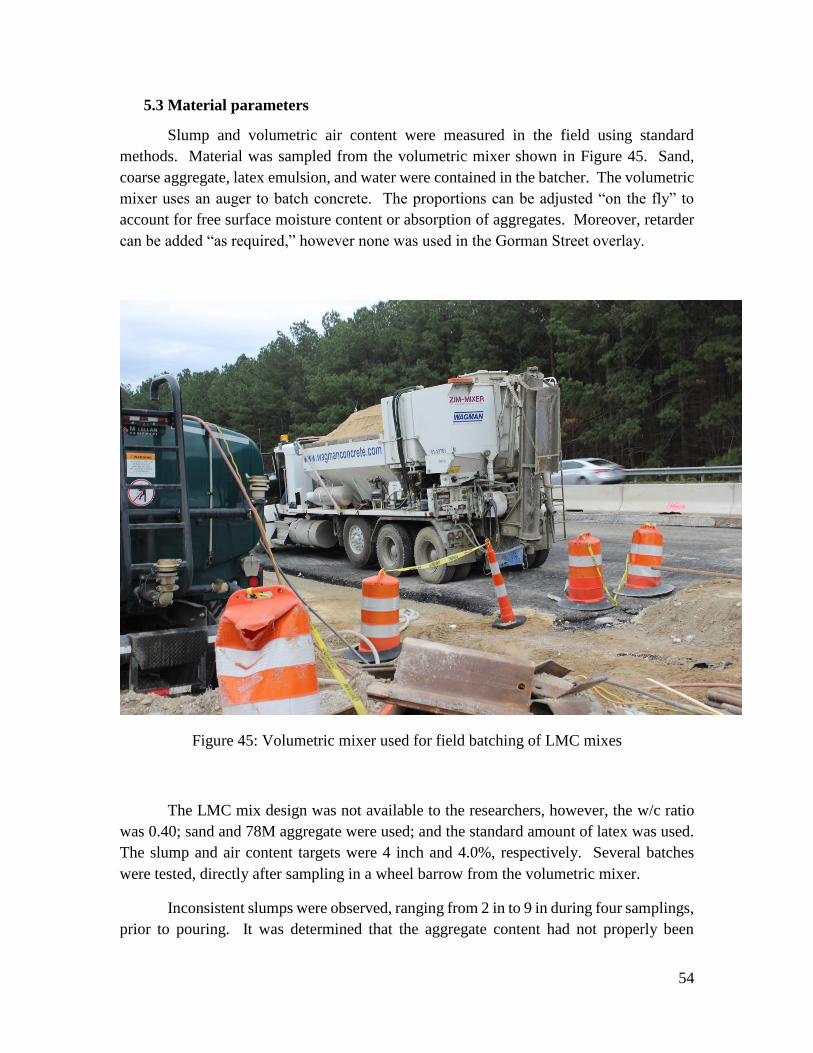
Slump and volumetric air content were measured in the field using standard
methods. Material was sampled from the volumetric mixer shown in Figure 45. Sand,
coarse aggregate, latex emulsion, and water were contained in the batcher. The volumetric
mixer uses an auger to batch concrete. The proportions can be adjusted “on the fly” to
account for free surface moisture content or absorption of aggregates. Moreover, retarder
can be added “as required,” however none was used in the Gorman Street overlay.
Figure 45: Volumetric mixer used for field batching of LMC mixes
The LMC mix design was not available to the researchers, however, the w/c ratio
was 0.40; sand and 78M aggregate were used; and the standard amount of latex was used.
The slump and air content targets were 4 inch and 4.0%, respectively. Several batches
were tested, directly after sampling in a wheel barrow from the volumetric mixer.
Inconsistent slumps were observed, ranging from 2 in to 9 in during four samplings,
prior to pouring. It was determined that the aggregate content had not properly been

55
adjusted for, and after calibration a slump of 4.5 in was obtained and deemed within
standards (shown in Figure 46). The entrained air, measured with a pressure pot, was also
inconsistent until the moisture calibration was made. Air contents ranging from 2.0 to
3.5% were measured, until a reading of 4.2% was found to be within the specification after
calibration.
Figure 46: Photograph of slump test performed on-site.
NCDOT specifications appear to have been adhered to, however, the adjustments
for aggregate moisture content added uncertainty as to the adherence of mix proportions.
After confirmation of the volumetric mix operator and the site foreman, the site where the
aggregate moisture content was measured was unknown. The addition of water at the
volumetric mixer deserved further study, as the w/c ratio is, broadly speaking, a good
predictor of material durability.
5.4 Construction procedures
Construction began by removing a plastic film (4 mils) covering the wet scarified
subsurface about 6 feet ahead of the finishing machine. The auger and rollers of the
finishing machine were set to the proper height before the fresh concrete was placed. Once
the machine was calibrated, the subsurface was rewet and the volumetric mixer was
positioned to pour. Some standing water on the scarified surface was visible after rewetting
(Figure 47).

56
Figure 47: rewetting the scarified surface directly before placing fresh concrete.
Concrete was placed directly in front of the auger of the finishing machine, which
moves the piled material to a more uniform height. Excess material is moved by shovel
before making contact with the auger. After the material was relatively uniform, the smooth
spinning roller finished the material to a flat surface. A photograph showing this procedure
is shown in Figure 48.
Figure 48: Auger-roller mechanical system used in the Gorman Street LMC bridge overlay.
While the material was being placed and finished, water was sprayed over the fresh
material using a pressurized sprayer to decrease evaporation. This is shown in Figure 49.
The water was sprayed over the heaps placed by shovel/volumetric mixer and the material
underneath the roller-finisher. The potential uncontrolled addition of water to the

57
unfinished fresh material can increase the w/c to an unknown and uneven value. This
certainly reduces the bulk material durability and may result in spalling if freezing and
thawing occurs in the areas material containing a high w/c ratio. For material being sprayed
under the roller-finisher, the top layer of cement paste will have a high w/c ratio and will
significantly lose abrasion resistance, freeze-thaw resistance, and will likely will
experience dusting. It is recognized that fogging of fine particles of water into the air over
concrete paving operations can be considered acceptable practice, provided this fogging
acts to increase the ambient humidity, and does not result in excess water being finished
into the concrete surface.
Figure 49: Spraying of water over the fresh concrete via a pressurized water sprayer.
The researchers left the bridge pour due to the presence of lightning before finishing
procedures could be observed. However, it was later confirmed that saturated burlap was
used after placing the LMC material. The use of saturated burlap is the preferred method
for curing the material and is effective in reducing the risk of cracking [5]. However, there
has been much discussion between researchers and industry regarding the placement of
unsaturated burlap. This topic is of special importance in LMC-VES material, which
hydrates quickly and has a larger water demand the OPC, the burlap must be placed in a

58
pre-saturated condition, and remain saturated during the entire curing process. Further
investigation into cracking resulting from unsaturated burlap is needed, as literature is
scarce.

59
6. Findings and Conclusions
This report investigates the use of fiber reinforcement in latex modified concrete
overlays. Due to the need to quickly reopen roadways, the use of rapid-set is commonly
used in North Carolina overlays. This study therefore focused on very early strength latex
modified concrete (LMC-VES). The report included a state of the art literature review,
extensive experimental program, and a review of current construction practices.
Based on the content of this report, the following conclusions are made:
1. When properly placed, finished and cured, concrete made with rapid-set cement
did not show any cracking in restrained drying and sealed shrinkage cracking
tests (ring tests), corrugated base restrained shrinkage tests, or in large-scale
restrained slab tests. Therefore the addition of fiber reinforcement to mitigate
the effects of restrained shrinkage was not required in these tests.
2. Plastic shrinkage cracking (ASTM C1579-13) was not observed in LMC-VES
material exposed to controlled environmental chamber conditions of 36°C +/-
1°C (97°F +/- 2°F) at a RH of 30% +/- 2% for 24 hours.
3. Surface cracking was observed in specimens (plastic shrinkage and corrugated
shrinkage) subject to:
a. Over finishing during rapid hardening,
b. Curing with partially saturated or non-rewetted burlap.
4. The addition of fiber makes finishing the surface more difficult and resulted in
a lower quality of finished surface.
5. Calorimetry results indicate that the addition of latex retards the hydration of
rapid-set cement paste (LMP) which may be desirable in reducing the risk of
thermal cracking.
6. The addition of citric acid as a retarding agent to LMP results in a complex
retardation effect which requires further investigation to better understand the
hydration kinetics.
7. During the evaluation of current practice, the following procedures were noted
to potentially have deleterious effects on the service life and increase cracking
of LMC overlays:
a. Uncontrolled spraying of water on unfinished and finished concrete,
possibly to be considered as over-fogging.
b. Ad-hoc addition of water at the volumetric mixer before material
inspection.
c. Placing (and finishing) of fresh concrete over a wetted and finished
surface.
d. Vibration of the deck.

60
In summary, the cracking of LMC-VES overlays may be most significantly affected by i)
the use of partially-saturated or non-rewetted burlap in the plastic state, ii) over finishing,
iii) construction procedures highlighted above, iv) temperature effects, v) settlement
cracking, and (vi) thickness of the slab greater than 3 inch.
7. Recommendations
The researchers recommend the following to potentially reduce the risk of cracking and to
potentially improve the service life of LMC-VES overlays:
1. Adherence to the NCDOT curing specifications, especially in the case of burlap
saturation and rewetting, is critical in preventing surface cracking. We
recommend that the burlap be saturated in short intervals (30-45 min) before
the opening of the road to traffic for a period as long as possible.
2. Finishing should be done as quickly as possible after the material is poured and
consolidated. Over finishing should be avoided.
3. The addition of water should be closely controlled at the volumetric mixer. Ad
hoc water addition procedures to correct for slump should be avoided.
4. Uncontrolled spraying of water on fresh material, material during finishing, and
finished material must be avoided.
5. Placing fresh concrete (and subsequent refinishing) on finished and re-wetted
material must be avoided.
6. The vibration of the bridge deck should be minimized as much as possible.
7. In general, due to difficulties in controlling the mixtures and placing of LMC-
VES, we recommend the use of this material only in cases where other materials
cannot be used due to requirements for quickly resuming traffic.

61
8. Technology Transfer Plan
The research team will meet with NCDOT committee to discuss the findings of the project
and if deemed appropriate, the research team will produce a presentation to present the
findings of this research to NCDOT technical staff, contractors, and other parties as
appropriate. The research team is currently working on expanding the findings of this
research project to potential publication in a refereed journal paper.
62
9. References
[1] Sprinkel, M.M. Rapid Overlays for Deck Preservation. Virginia Concrete Conference,
Richmond, VA. 2011.
[2] Sprinkel, M.M. LMC Overlays for Bridge Deck Preservation. 2011 Southeast Bridge
Preservation Partners Meeting, Raleigh, NC. 2011.
[3] Thompson, N., Yunovich, M., and Dunmire, D J. “Corrosion Costs and Maintenance
Strategies – A Civil/Industrial and Government Partnership,” Materials Performance,
44(9), 2005.
[4] Ghasemzadeh F, and Pour-Ghaz M. The Effect of Damage on Moisture Transport in
Concrete. Journal of Materials in Civil Engineering – ASCE. 2014; online at
http://dx.doi.org/10.1061/(ASCE)MT.1943-5533.0001211
[5] Pendergrass, B., and Darwin, D. Low-Cracking High-Performance Concrete (LC-
HPC) Bridge Decks: Shrinkage-Reducing Admixtures, Internal Curing, and Cracking
Performance. The University of Kansas Center for Research, Inc. 2014.
[6] Boatman, B. Rigid Overlays: Expected Service Life. Michigan Department of
Transportation, 2010.
[7] Okba, S.H., El-Dieb, A.S., and Reda, M.M. Evaluation of the Corrosion Resistance of
latex Modified Concrete (LMC). Cement and Concrete Research, 27(6), 1997.
[8] Wenzlick JD. Evaluation of Very High Early Strength Latex Modified Concrete
Overlays. Missouri Department of Transportation. 2006.
[9] High Early Strength Concrete Overlays, Office of Materials Management, Cement &
Concrete Section, Ohio Department of Transportation, 2007.
[10] Sprinkel, M.M. Latex-Modified Concrete Overlay Containing Type-K Cement.
FHWA/VTRC 05-R26, Virginia Department of Transportation. 2005.
[11] Banthia, N. and Bupta, R. Influence of Polypropylene Fiber Geometry on Plastic
Shrinkage Cracking in Concrete. Cement and Concrete Research, 36: 1263-1267, 2006.
[12] Bentz, D.P., and Jensen, O.M. Mitigation Strategies for Autogenous Shrinkage
Cracking. Cement and Concrete Composites, 26: 677-685, 2004.

63
[13] Issa MA, Alhassan MA, Ramos JC. Glass Fiber-Reinforced Latex-Modified
Concrete – Using a volumetric mixer for production of overlays. Concrete International,
29(3): 48-52, 2007.
[14] Kim, D. and Park, C. Resistance of Latex-Modified Fibre Reinforced Concrete for
Precast Concrete Pavement Application.
[15] Krauss, P.D. and Rogalla, E.A. Transverse Cracking in Newly Constructed Bridge
Decks. National Cooperative Highway Research Program Report 380, Transportation
Research Board, Washington, D.C. 1996.
[16] Hall, C. and Woff W. D. Water transport in brick, stone, and concrete. London and
New York, New York, NY. 2002.
[17] Castro, J. Moisture transport in cement based materials: Application to transport
tests and internal curing. PhD Thesis. Purdue University, West Lafayette, ID. 2011.
[18] Mindess, S. Young, J., Darwin, D. Concrete. 2nd Edition. Prentice Hall, Upper
Saddle River, NJ. 2003.
[19] Banthia, N., and Gupta, R. Influence of Polypropylene Fiber Geometry on Plastic
Shrinkage Cracking in Concrete. Cement and Concrete Research. 37(6). 2006.
[20] Hossain, A. Assessing Residual Stress Development and Stress Relaxation in
Restrained Concrete Ring Specimens. PhD Thesis, Purdue University, West Lafayette,
ID. 2003.
[21] Mehta, P.K. and Monteiro, P.J.M. Concrete: Structure, Properties, and Materials.
2nd Edition, Prentice Hall, Englewood Cliffs, NJ, 1993.
[22] Pickett, G. Effect of Aggregate Shrinkage of Concrete and a Hypothesis Concerning
Shrinkage. ACI Journal. 52(5). 581-590. 1956.
[23] Scherer, G. W. Drying, Shrinkage, and Cracking of Cementitious Materials.
Transport in Porous Media. DOI 10.1007/s11242-015-0518-5.
[24] Lura, P., Wyrzykowski, M., Tang, C., Lehmann, E. Internal curing with lightweight
aggregate produced from biomass-derived waste. Cement and Concrete Research. 59.
24-55. 2014.
[25] Henkensiefken, R., Bentz, D., Nantung, T., Weiss, J. Volume change and cracking
in internally cured mixtures made with saturated lightweight aggregate under sealed and
unsealed conditions. Cement and Concrete Composites. 31. 427-437. 2009.

64
[26] Wu, Z., Wong, H.S., and Buenfeld, N.R. Influence of drying-induced microcracking
and related size effects on mass transport properties of concrete. Cement and Concrete
Research. 68. 35-48. 2015.
[27] Perenchio, W.F. The Drying Shrinkage Dillema. Concrete Construction. 379-38.
1997.
[28] Hajibabaee, A., and Ley, T. The impact of wet curing on curling in concrete caused
by drying shrinkage. Materials and Structures. DOI: 10.1617/s11527-015-0600-z
[29] Ramey, E. G. and Cope, B. L. Laboratory performance of shrinkage compensating
concrete mixtures designed to reduce drying shrinkage cracking in Alabama. Highway
Research Center, Dept. of Civil Engineering, University of Auburn. 1999.
[30] Suprenant, B. A. and Malisch, W. R. The Fiber Factor – Lab Tests Show the
Benefits of Using Synthetic Fibers to Limit Subsidence Cracking of Reinforced Concrete.
Concrete Construction. 1999.
[31] Shaeles, C., and Hover, K. Influence of mix proportions and Construction
Operations on Plastic Shrinkage Cracking in Thin Slabs. ACI Materials Journal. 85(6).
495-504. 1988.
[32] Nair, S., and Little, D. Water as the key to expansion of ettringite in cementitious
materials. Transportation Research Record: Journal of the Transportation Research
Board, No. 2104. 55-62. 2009.
[33] Möschner, G., Lothenbach, B., Figi, R., and Kretzschmar, R. Influence of citric acid
on the hydration of Portland cement. Cement and Concrete Research. 39. 275-282.
2009.
[34] Leeman, A., Nygaard, P., and Lura, P. Impact of admixtures on the plastic shrinkage
cracking of self-compacting concrete. Cement and Concrete Composites. 46. 1-7. 2013.
[35] Kong, X., Pakush, J., Jansen, D., Emmerling, S., Neubauer, J., and Goetz-Neuhoffer,
F. Effect of polymer latexes with cleaned serum on the phase development of hydrating
cement pastes. Cement and Concrete Research. 87. 30-40. 2016
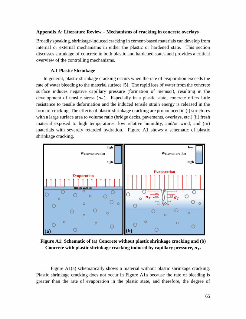
65
Appendix A: Literature Review – Mechanisms of cracking in concrete overlays
Broadly speaking, shrinkage-induced cracking in cement-based materials can develop from
internal or external mechanisms in either the plastic or hardened state. This section
discusses shrinkage of concrete in both plastic and hardened states and provides a critical
overview of the controlling mechanisms.
A.1 Plastic Shrinkage
In general, plastic shrinkage cracking occurs when the rate of evaporation exceeds the
rate of water bleeding to the material surface [5]. The rapid loss of water from the concrete
surface induces negative capillary pressure (formation of menisci), resulting in the
development of tensile stress (𝜎𝑇 ). Especially in a plastic state, concrete offers little
resistance to tensile deformation and the induced tensile strain energy is released in the
form of cracking. The effects of plastic shrinkage cracking are pronounced in (i) structures
with a large surface area to volume ratio (bridge decks, pavements, overlays, etc.) (ii) fresh
material exposed to high temperatures, low relative humidity, and/or wind, and (iii)
materials with severely retarded hydration. Figure A1 shows a schematic of plastic
shrinkage cracking.
Figure A1: Schematic of (a) Concrete without plastic shrinkage cracking and (b)
Concrete with plastic shrinkage cracking induced by capillary pressure, 𝝈𝑻.
Figure A1(a) schematically shows a material without plastic shrinkage cracking.
Plastic shrinkage cracking does not occur in Figure A1a because the rate of bleeding is
greater than the rate of evaporation in the plastic state, and therefore, the degree of

66
saturation is uniform and no capillary pressure gradient is present. Contrasting this, Figure
A1b shows a material exposed to a higher rate of evaporation. Since evaporation is
occurring, the surface material is drying in the plastic state, inducing a sharply non-uniform
saturation and the capillary pressure gradient, 𝜎𝑇. As a response to 𝜎𝑇, the fresh concrete
material releases tensile strain energy in the form of a crack.
The length of plastic shrinkage cracks corresponds to the depth of capillary tensile
stresses; in concrete mixed with ordinary Portland cement, a typical plastic shrinkage crack
depth is 2-3 inches [15]. The cracks may be discrete or distributed, but they always occur
in the location(s) of maximum tensile stress of the fresh concrete, such as areas where
bleeding is restricted and/or where the depth of the fresh material is minimized. Areas
where such stress concentrations may develop also include fresh concrete directly above
rebar, surrounding large aggregates, or surrounding dowel rods. The effects of stress
concentration are simulated by the ASTM C1579-13 test method. Note that because plastic
shrinkage cracks may occur directly above large inclusions, non-distributed plastic
shrinkage cracks are often confused with settlement cracks.
Plastic shrinkage cracking can be controlled by reducing the rate of evaporation
and/or by increasing the rate of bleeding. Reducing the rate of evaporation can be done
using construction methods and practices such as (i) locally increasing the relative
humidity (RH) using foggers, (ii) using wind barriers, (iii) covering the material with an
impermeable membrane, (iv) pouring at lower ambient temperatures, (v) partial water
replacement with ice, (vi) addition of liquid nitrogen, (vii) aggregate chilling, and (viii)
flooding (not recommended). Although these methods (and many more) may be effective,
they may also be monetarily expensive and are typically reserved for structures such as
bridge decks.
In some instances, plastic shrinkage cracking occurs when concrete is poured in
cold weather. This results from low ambient relative humidity and the retardation of
cement hydration. Control of temperature and evaporation is often accomplished using
insulators, wind blocks, and/or polymeric membranes.
Modification of the hydraulic properties can have a significant impact on the
susceptibility of concrete to plastic shrinkage cracking. In the context of bridge decks,
pavements, and overlays, a major goal of the material design it to decrease material
permeability (more specifically, saturated hydraulic conductivity). This improves the
structure’s durability by increasing its resistance to saturation by water and potentially
aggressive chemical agents [4, 16, and 17]. Some common methods for reducing
permeability are (i) reducing the w/c ratio, (ii) including fine aggregate and mineral content
with a high surface area to volume ratio (such as silica fume), (iii) optimizing the pore-size
distribution, (iv) increasing the aggregate content using optimization methods, and (v)
using polymeric emulsion (i.e. latex). While increasing the material’s resistance to
67
moisture ingress certainly improves long-term durability, it may also decrease the
movement of bleed water during the plastic stage which could aggravate plastic shrinkage.
In addition to modifying aggregate, cement content, and mineral admixtures,
chemical admixtures are commonly used to reduce the water-to-cement (w/c) ratio. High-
range water reducers and superplasticizers are very effective at reducing the w/c ratio,
however, they may also reduce the bleeding capacity. The reduction in bleeding capacity
in this case is largely due to increasing the solid content of the fresh concrete. On the other
hand, water-reducing admixtures containing hydroxylated carboxylic acid have been
shown to increase the rate of bleeding [15]. It should be noted that reducing w/c ratio
increases the risk of shrinkage cracking as well.
Controlling (i.e., accelerating) the rate of cement hydration may also be an effective
method of reducing plastic shrinkage. Materials exposed to unfavorable environmental
conditions (high temperature, wind, and low RH) in the plastic state have a higher risk of
plastic shrinkage cracking [18]. Increasing the rate of hydration reduces the exposure of
fresh material to the environment, and thus can decrease the risk of plastic shrinkage
cracking. Set acceleration is commonly utilized in overlays with rapid-setting cement.
Chemical admixtures are also effective for increasing the rate of hydration; however,
special care should be taken in the selection and dosing of accelerators to avoid thermal
cracking and to avoid excess chloride content.
The addition of fibers is another technique that has been shown to be highly
effective at controlling plastic shrinkage cracking [19]. Generally, shorter fibers (< 0.25
inch) with a high aspect ratio (fiber length divided by fiber diameter) are effective at
reducing the frequency of cracking and the width of plastic shrinkage cracks. Fibers in
dosages of 0.1% - 0.3% by volume (usually equivalent to around 1 lb/yd3) increase the
tensile capacity of the plastic and hardened systems, resulting in reduced cracking
potential. Fiber-reinforced systems with plastic shrinkage cracking also benefit from a
reduction in crack width, resulting in comparatively lower crack permeability as compared
to non-reinforced systems.
A.2 Drying Shrinkage
Drying shrinkage can result from a volumetric dilation in concrete that occurs due to
variation in moisture and temperature [20]. The volumetric dilation occurs in the presence
of moisture due to capillary suction, and can be computed mathematically from equilibrium
of the peak pore pressure and the compliance of the material. However, when this the
volume change is sufficiently restrained, cracking can occur when the tensile strength of
the concrete is reached. Similarly, if tensile stresses due to restraint are below the tensile
strength of the concrete, then the material will not crack. Moreover, if concrete is exposed
to sustained tensile (or compressive) loading for long periods, creep relaxation will occur
[21].
68
The majority of drying shrinkage occurs at early stages of exposure. Drying shrinkage
is also a partially reversible process, meaning that when the material is fully rewetted only
a fraction of the volume change remains [20]. This fraction was estimated at approximately
60% in a fundamental shrinkage study conducted in 1956 [22]. This pattern holds true for
cyclic wetting and drying cycles – shrinkage during later cycles decreases, which is most
likely due to viscoelastic relaxation and rearrangement of the material particles [23].
Material constituents in concrete have a significant impact on drying shrinkage – the
amount of water and the type and amount of cement being the most dominant. The total
volumetric dilation of concrete has been shown to be inversely proportional to the elastic
modulus of the aggregate and linearly proportional to the w/c ratio (up to a w/c = 0.6) [23].
Research has shown that shrinkage reducing admixtures (SRAs) significantly reduce
drying and plastic shrinkage [24]. Recently, internal curing using saturated light weight
aggregates (LWA) have been shown to profoundly reduce the rate of drying shrinkage, the
volume of autogenous shrinkage, and increase the internal RH of materials tested in [24].
LWAs may also significantly decrease shrinkage in materials with low w/c with optimized
aggregate spacing [25].
When cementitious materials are dried to low levels of saturation, microcracking
occurs [26]. This microcracking exposes unhydrated cement which will begin hydrating
when rewetted [21]. This complicates the issue of shrinkage, but likely only has a profound
effect at low w/c ratios since a larger portion of the cement is unhydrated (compared to w/c
ratios >0.42). This is especially relevant in concrete overlays, which often have a regulated
maximum w/c of ~0.38 – 0.40 for VES-LMC overlays by many state DOTs.
There are numerous material properties that can be optimized to improve the
performance and mitigate against the effects of shrinkage. However, the effect of curing
on drying shrinkage, and shrinkage in general, is significant. In structures consisting of
concrete with Portland cement, wet curing is often used. Moist curing is often considered
as the preferred method mitigate against moisture and temperature loss in structures with a
high surface area to volume ratio, such as bridge decks. When moisture loss is significant,
plastic shrinkage may occur in addition to reductions in abrasion resistance and strength.
Furthermore, the surface permeability will increase and result in reduction in durability [5].
Wet curing for long durations has shown to increase drying shrinkage, as shown in
[27], in which wet curing lasted 7 days. Curing is of particular importance in the discussion
of drying shrinkage of overlays, which are often exposed to harsh environments and have
a low w/c ratio. In pavements and overlays using rapid-set cement, where the water
demand is higher than Portland cement, the role of curing on hardened properties is
amplified. In early-age concrete with a w/c ratio < 0.40, the generation of hydration
products via self-desiccation (autogenous shrinkage) has greater effect on shrinkage [28].
In restrained systems, this leads to higher internal tensile stresses and greater potential for
69
cracking [28]. In LMC-VES overlays, optimal curing may not be feasible, as the rapid
reopening of a road largely controls construction and curing procedures.
While there is a wealth of research available in drying shrinkage of Portland cement,
much less is known about restrained drying shrinkage of Rapid-Set cement. Nonetheless,
the mechanism of drying shrinkage in concrete containing Rapid-Set cement is the same
as Portland cement, although early-age expansion occurs in rapid-set cement due to the
formation of ettringite. In [29], researchers showed that Type K cement is effective in
reducing drying shrinkage. The authors reported that restrained shrinkage was less than
half of what may be expected from Portland cement (with the same w/c) using ring tests
and restrained bars. It should be noted that this study did not investigate Rapid-Setting
cement. Moreover, the effects of latex emulsions and retarding agents on drying shrinkage
of concrete containing Type K and Rapid-Set cement is unavailable in literature.
A.3 Thermal Cracking
Thermal volumetric dilation occurs in materials when they are exposed to an increase
or decrease in temperature. This volume change is generally not deleterious in concrete
until the plastic material hardens and gains sufficient stiffness to develop stresses due to
restraint. One exception to this statement is the occurrence of non-linear temperature
distribution present in large concrete structures and structures using rapid-setting or high-
early strength concrete. In such systems, thermal gradients may be high during hydration
[21].
A.4 Settlement Cracking and Cracking from Finishing
Settlement cracking occurs when consolidated concrete continues to settle around an
inclusion, such as a dowel or rebar. The settlement creates a region of tensile stress, which
is typically perpendicular to the concrete surface (the smallest cross-section has the highest
tensile stresses). Generally, the settlement region also has lower compressive strength than
the surrounding material after subsistence.
Optimizing aggregate gradation, slump, and increasing cover over bars decreases the
chance of settlement cracking. Improving construction procedures, especially
consolidation, also reduce the risk settlement cracking. Moreover, [30] showed that
polypropylene fiber reduced settlement cracking. The reduction of settlement cracking
was likely due to increasing tensile strength of plastic concrete and improving the
cohesiveness of the fresh concrete.
Over finishing and using improper finishing procedure can lead to significant
cracking, as reported in [31]. In [31], the authors found that strike-off speed is a significant
variable in transverse cracking of thin slabs. Over finishing plastic concrete may be a
significant concern in overlays, which are essentially thin slabs. In rapid-setting material
(LMC-VES), finishing may occur immediately before initial set – potentially requiring

70
higher finishing pressure, thus inducing elevated shear stresses. The effects of finishing
on cracking of LMC-VES material has yet to be researched.