the union gas parkway west project - etouches · the union gas parkway west project ... compressor...
TRANSCRIPT
SYMPOSIUM OF THE INDUSTRIAL APPLICATION OF GAS TURBINES COMMITTEE BANFF, ALBERTA, CANADA OCTOBER 2015
15-IAGT-302
THE UNION GAS PARKWAY WEST PROJECT Erin Wishart, Bob Wellington
Union Gas Limited
The Union Gas Parkway West Compressor Station project is a greenfield natural gas
compressor station being constructed in 2014 and 2015 at the east end of Union’s
Dawn to Parkway pipeline transmission system in the Town of Milton, Ontario. This
new station is intended to enhance the reliability and security of gas supply to more than
five million people who live and work in the Greater Toronto Area and markets beyond.
The station consists of two Siemens (formerly Rolls Royce) RB211-24GT-RT61 driven
centrifugal compressor sets, one single case and one tandem case.
This is a unique and challenging project in that the station is being constructed on a
rural, agricultural property sandwiched between two built-up communities in a highly
planned municipality. As such, future plans for adjacent lands must be carefully
considered in the facility design and emissions modelling. The site is also dissected by
a regulated watercourse, which presents unique challenges in working with local
conservation authorities to understand and implement requirements to minimize impacts
to local waterways and drainage.
From an equipment perspective, the design phase of the project presented an
opportunity to take several lessons learned on recent projects and work with the gas
turbine OEM to customize and optimize the GT packaging design to positively affect
both construction and future maintenance work. Through this process, a design was
established which will be re-used on future projects, saving on engineering time and
expense not only for the gas turbine but also the plant in its entirety.
As with any project of this nature, there were also some interesting challenges to
overcome during the construction phase of the project.
This paper will focus on the unique challenges of developing a green field compressor
station in a highly planned community. It will cover the environmental and noise
considerations required to meet provincial regulations, but also the other considerations
pertaining to site infrastructure that must be taken to meet municipal requirements.
Unique aspects of the compressor package design and the benefits of the design

Erin Wishart/ Bob Wellington
2
optimization process will be discussed, along with some review of the construction and
commissioning challenges encountered during the project execution phase.
Introduction
Union Gas is a 104 year old natural gas storage, transportation and distribution
company based in Chatham, Ontario, and is a subsidiary of Spectra Energy. Union
serves 1.4 million residential, commercial, and industrial customers within its franchise
areas in Ontario while also provides storage and transportation services to ex-franchise
customers in the Greater Toronto Area (GTA), Eastern Canada and the Northeastern
United States.
At the heart of Union Gas’s operation is the Dawn to Parkway Transportation system.
This pipeline network serves primarily to move gas from Union’s Dawn Hub, where it is
imported and stored, easterly to the Parkway Compressor Station, located in
Mississauga, Ontario. Along the way, Union’s distribution network in Southwestern
Ontario is served by the Dawn to Parkway pipelines. From Parkway Compressor
Station, gas is exported to TransCanada Pipelines and Enbridge Gas Distribution for
use east of Union’s distribution franchise area. The compressors at Parkway ensure
minimum pressures to these pipelines are maintained. Figure 1 below illustrates the
Dawn to Parkway transportation corridor, as well as the area over which natural gas
stored at Union’s Dawn Hub is transported and distributed for end use.
Figure 1: Dawn to Parkway Pipeline System and Service Area for Dawn Hub
Initially the Parkway Compressor Station consisted of one compressor, Parkway “A”, an
Avon 1534 RT48S driven RFBB30 compressor, having an ISO power rating of about
18,200 hp. In 2007, Union constructed the Parkway “B” compressor, a 44,500 hp (ISO)
Siemens RB211-GT DLE RT61 driven tandem RFBB36 compressor set. Parkway “B”
was designed to meet new demands for service on the Dawn to Parkway system. Prior
to the installation of Parkway “B”, Union had utilized a loss of critical unit (LCU) design
strategy for the Dawn to Parkway transmission system, meaning that the system was

THE UNION GAS PARKWAY WEST PROJECT
3
designed with back up compression to cover off a failure during peak day operation.
Specifically, for Parkway “A”, back up compression was provided by compressors
upstream of the Parkway site. Following installation of the Parkway “B” compressor,
there was insufficient upstream back-up compression to support design day conditions
in the event of an unplanned outage at Parkway.
After four years of operating the Parkway “B” compressor and having managed to
sustain operations through several unplanned shut downs, Union Gas recognized the
consequences of a major failure at Parkway in terms of security of supply. To mitigate
this risk, a plan was initiated to construct an LCU compressor at the Parkway site. This
new compressor would be named Parkway “C”.
Initial design reviews revealed that the existing property was too small to accommodate
a third compressor plant of this size, and still maintain appropriate set back from
neighbouring properties. In response, Union located and purchased a property
approximately 500m west of the existing station, in the neighbouring Town of Milton.
The new site would be known as Parkway West; and the existing Parkway Compressor
Station was renamed Parkway East. Figure 2 illustrates the two sites.
Figure 2: Aerial Photo of the Parkway West and Parkway East Properties
At the time that Union began plans for the Parkway West site, market interest in Dawn
to Parkway capacity drove the requirement for a second compressor at Parkway West.
This compressor would be named Parkway “D”.
Erin Wishart/ Bob Wellington
4
In addition to the two compressors, the Parkway West site offered an opportunity to
bolster system reliability through additional connections into pipelines that carry gas
easterly. Each new connection drove the requirement for a new gas measurement site.
With these additional facilities, the final scope for the site would include two new 45,000
hp (ISO) RB211 24GTDLE RT61 driven compressor sets, three custody transfer sites to
meter gas into connecting pipelines, and a new Operations Centre to serve as the home
base for operations and maintenance personnel for both Parkway stations. The
collective cost of the site represented an investment of over $300 million in new assets
for Union Gas to reinforce existing services and meet new demands on the Dawn to
Parkway system.
Lands, Permits, and Stakeholder Engagement
Rezoning
The newly acquired Parkway West property was designated as Agricultural and
Greenlands and would require rezoning to allow construction of a natural gas
compressor station. The zoning amendment required public consultation, including
review by adjacent landowners and other stakeholders, prior to approval being granted
by the Town of Milton. As expected, some neighbouring residents had concern over
safety issues associated with the facility. These concerns were satisfied through
discussions with Union’s technical staff about the extensive safety systems that are a
fundamental part of the design. Other residents were concerned over impacts to the
value of their land because of the potential appearance and sound of the site. Union
was able to alleviate this by inviting the concerned parties to the existing Parkway East
site, which is well screened from the adjacent lands and very heavily silenced. This
enabled the landowners to experience first-hand how little impact the new site would
have once complete. In addition, Union shared designs studies for site noise and air
emissions with the concerned parties who, in one case, hired their own consultant to
audit the information presented in the studies. After review of the information
presented, all concerns were satisfied with the caveat that the site emissions reports be
updated after commissioning and shared with the concerned parties.
The rezoning process also prompted involvement by the local heritage association who
reviewed the homes residing on the Parkway West property. Their assessment led to a
designation of these homes as heritage sites. As a condition of the zoning amendment,
Union was tasked with establishing revitalization and maintenance plan for the homes.
Figure 3 illustrates one of the heritage homes now owned and maintained by Union
Gas.

THE UNION GAS PARKWAY WEST PROJECT
5
Figure 3: Heritage Home Located on Parkway West Property
Site Plan Approval
In general, the requirements for site plan approval were easy to incorporate into Union’s
design, although they created substantial additional work and impacted the project
schedule and cost. Some key points that were negotiated directly with municipal
officials were screening and landscaping, number of entrances, firewater system
design, road design, and fence details.
More challenging than the requirements of the municipality were those of the local
conservation authority. The site property is dissected by a regulated tributary and is
adjacent to a wetland. Each posed new challenges for Union Gas’s project team.
Crossing of the regulated tributary with any site infrastructure, including roads and site
services, required special permits be issued by the conservation authority. Further
complicating the site design, a 30m wide buffer zone had to be maintained on each side
of the tributary and wetland in which no development would be allowed, as this is
considered regional flood plain. Including other property which was naturalized to
create snake and bird habitat, 34 of 119 acres purchased by Union for the Parkway
West compressor station could not be developed as part of the project, and was to be
designated as Environmental Protection Area. In addition over 5 acres were dedicated
to storm water retention. Figure 4 shows the Parkway West property and allowed land
use around the site. The zones coloured in light yellow and blue represent
environmental protection area and storm water management facilities, respectively.
In addition to design challenges presented by the conservation authority, a great deal of
design work was generated through the site plan approval process. Multiple revisions
of approximately 100 supplemental drawings were specifically generated to obtain site
plan approval from the municipality for the site. Generating and awaiting approval for
these drawings added considerable time and effort to the design schedule for the
project and delayed the start of certain construction activities.

Erin Wishart/ Bob Wellington
6
Figure 4: Parkway West “Developable Area” Plan
First Nations Consultation
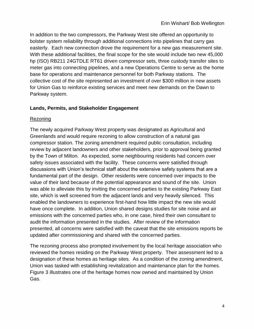
One unique feature added to the Parkway West design incorporated a concept
discussed through the extensive First Nations consultation process. A one acre Native
Healing garden in the shape of a turtle was added to the design of the site as shown in
Figure 5. Union engaged a local traditional First Nations landscaping company to design
THE UNION GAS PARKWAY WEST PROJECT
7
and build the garden featuring medicinal and traditional plants used in the First Nations
culture and will be accessible to the public to enjoy.
Figure 5: Native Healing Garden at Parkway West
Equipment Design
Compressor/Turbine Selection
Performance capabilities for the Parkway “C” compressor were to be sufficient to back
up the existing 44,500 hp Parkway “B” compressor. Immediate and future contracts for
service offered by the Parkway “D” compressor drove approximately the same power
rating as Parkway “C”.
The Parkway “C” project was initiated prior to the Parkway “D” project, and an RFP was
issued to 3 different compressor vendors for Parkway “C” first. With an existing turbine
fleet which consists of 11 variants of the RB211, Union considered spares inventory,
training, operational staff flexibility and standardized design as a part of the bid analysis.
The introduction of new equipment into the fleet would present additional costs and
potentially reduce flexibility in terms of moving staff around for operations. Furthermore,
the offering by Siemens could be more easily customized, and had to a degree, already
been customized by Union Gas through past projects. Through a complete bid
analysis, Union opted to select the Siemens RB211 24GTDLE RT61 driven RFBB42 for
Parkway “C”. The same criteria that was used in selecting Parkway “C” was then
employed for selecting the Parkway “D” compressor. Parkway “D” would be a Siemens
RB211 24GTDLE RT61 driven tandem 2 x RFBB36 compressor set with single case,
parallel and series operational capability.
Erin Wishart/ Bob Wellington
8
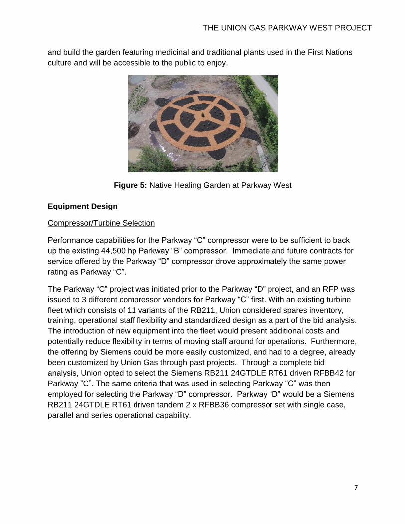
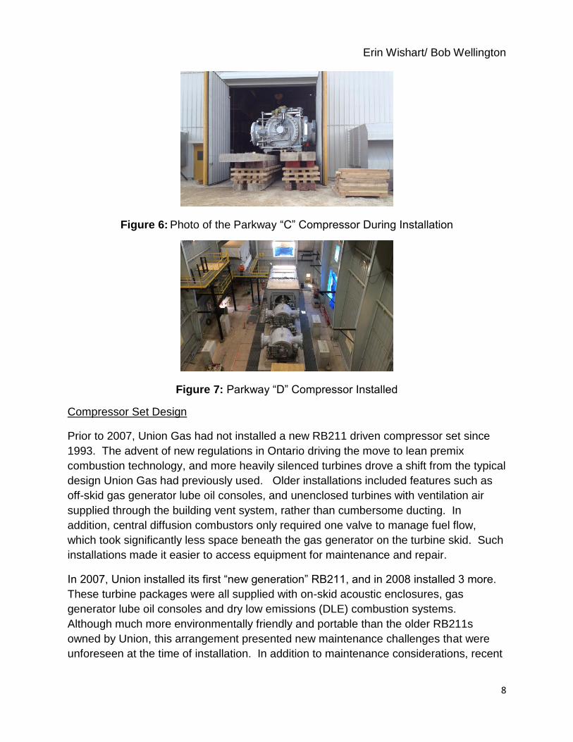
Figure 6: Photo of the Parkway “C” Compressor During Installation
Figure 7: Parkway “D” Compressor Installed
Compressor Set Design
Prior to 2007, Union Gas had not installed a new RB211 driven compressor set since
1993. The advent of new regulations in Ontario driving the move to lean premix
combustion technology, and more heavily silenced turbines drove a shift from the typical
design Union Gas had previously used. Older installations included features such as
off-skid gas generator lube oil consoles, and unenclosed turbines with ventilation air
supplied through the building vent system, rather than cumbersome ducting. In
addition, central diffusion combustors only required one valve to manage fuel flow,
which took significantly less space beneath the gas generator on the turbine skid. Such
installations made it easier to access equipment for maintenance and repair.
In 2007, Union installed its first “new generation” RB211, and in 2008 installed 3 more.
These turbine packages were all supplied with on-skid acoustic enclosures, gas
generator lube oil consoles and dry low emissions (DLE) combustion systems.
Although much more environmentally friendly and portable than the older RB211s
owned by Union, this arrangement presented new maintenance challenges that were
unforeseen at the time of installation. In addition to maintenance considerations, recent

THE UNION GAS PARKWAY WEST PROJECT
9
operational experience and a failure mode and effects analysis for the new generation
RB211 packages had highlighted some opportunities to improve equipment reliability.
By collaborating with Union’s project design team, Siemens was able to provide Union
with an enhanced package design to fit their operational and maintenance needs.
Some key features which were custom designed into the Parkway West gas turbine
packages to and the issues addressed by each are tabulated in Table 1.

Erin Wishart/ Bob Wellington
10
Table 1: Custom Design Features
Issue Solution
Sticking bypass solenoid starving power turbine oil distribution system of pressure with no indication of position
Added differential pressure gauge across solenoid for easy troubleshooting
Oil misting from coupling cooling air vents into compressor building because of back pressure through vent piping and standard demister
Power vented demister
No in-line oil sampling connections so source of wear metals cannot be detected
Added lube oil sample connections at LO return lines just past bearings for the power turbine and compressor journal bearings
Standard on tank lube oil level transmitter requires tank to be drained for calibration
Added a small off-tank reservoir for the level transmitter that could be isolated from the tank and drained independently
Standard installation for gas generator lube oil skid and associated transmitters is inside the turbine enclosure beneath the gas generator. Access for skid for inspection/repair is restricted.
Moved the console off-skid allowing easy access for removal of pumps with a small lift.
250 hp starter pump and motor located directly below the combustion air inlet duct so access with the overhead crane is impossible without removal of the duct
Relocate the starter motor to the gas generator lube oil skid and situate for access by building overhead crane should removal become necessary
Vertically mounted enclosure ventilation fans make removal difficult without special tooling/tables and/or removal of additional duct work
Relocate the fans and reorient horizontally to allow the fans to be lifted directly by the building crane
Inspection hatches in the air inlet ducting inaccessible without cat walks which would need to be mounted to the enclosure
Integrated enclosure catwalk/ladder system that was compatible with the surrounding building catwalk system
Systemic charger card failures for UPS inverter
Siemens changed card manufacturers and had the assembly recertified by CSA
Turbine enclosure ventilation exhaust duct mounted gas detector located over turbine output shaft, approximately 8 m above the floor, and inaccessible without special lift
Relocate duct mounted gas detector to the enclosure side of duct for accessibility from enclosure catwalk system
Hysteresis causing oscillations and eventual failure of fuel metering valves
On-skid control boxes reducing communication cable length and capacitance

THE UNION GAS PARKWAY WEST PROJECT
11
Figure 8 through Figure 10 below illustrate some of the design improvements described
above.
Figure 8: On Skid Gas Generator Lube Oil Console Design and New Off Skid Design
Figure 9: Vertical Turbine Enclosure Vent Fan Configuration & New Horizontal Design
Figure 10: Original Duct Mounted Gas Detector Location and New Location

Erin Wishart/ Bob Wellington
12
Station Infrastructure Design Highlights
Noise
The Parkway West site is located in a predominately agricultural area which abuts
heavy residential development. Furthermore, the adjacent agricultural properties will
eventually be re-zoned for residential and employment lands development. Although
the east property limit abuts a heavily travelled provincial highway, noise limitations
required by the Ontario Ministry of Environment for new industrial developments were
part of the project design basis. Additional noise created by operation of the facility
could not generate noise at levels higher than 45 dBA at night at the nearest residence,
and 50 dBA during daytime hours.
To ensure noise generated by the site was minimal, equipment was designed to a
maximum allowable noise limit of 35 dBA @100m and substantial measures were
included in the design to reduce noise generated from the gas turbine package,
compressors, auxiliary equipment, and gas carrying piping. For example, all above
grade plant piping and valves are lagged with 8” of mineral wool insulation and a layer
of 2lb/ft2 mass loaded vinyl as shown in Figure 11.
Figure 11: Acoustic Insulation Installation
Also the compressor building itself acts as an acoustic enclosure around the gas turbine
enclosure, which is already designed to reduce noise to 85 dBA @ 100m. All
compressor building ventilation and exhaust openings are fitted with baffled silencing
hoods, and all large doorways which are normally supplied with roll-up doors were
supplied with heavily insulated barn-style doors. Finally the air intake and exhaust
silencing systems were upgraded from the base design to limit noise generated to 35
dBA @100m, rather than the 38 dBA @ 100m used for previous Union Gas designs.
Figure 12 below illustrates the extent to which the compressor buildings were silenced.

THE UNION GAS PARKWAY WEST PROJECT
13
Figure 12: Parkway C and D Compressor Buildings
All of these measures ensure that noise levels are maintained within provincial
guidelines for existing homes and for homes that may be built as part of future
residential development in this area.
“Green” Upgrades to the Standard Design
The design team took it upon themselves to look for sources of emissions that could be
reduced at a reasonable cost without affecting plant reliability. Some features added
into the plant design differ from Union’s standard compressor station designs and are
considered green upgrades, including the following:
1. Electric valve actuators have been selected for all non-critical valves which do
not fail to the closed position on an Emergency Shut Down (ESD) in lieu of gas
powered pneumatic or pneumatic/hydraulic actuators
2. Electric 24VDC linear valve actuators equipped with super-capacitors to enable a
fail position have been added to some non-critical plant valves on a trial basis in
lieu of gas powered pneumatic, spring return actuators
3. Bleed air isolation solenoids have been installed on valve positioner pneumatic
supply bleed lines which shut off air flow when the valve is inactive in lieu of
constantly bleeding
4. A blow down recovery compressor was added to allow plant piping to be drawn
down to low pressure before venting the gas for routine maintenance.

Erin Wishart/ Bob Wellington
14
Construction
Site Infrastructure
Construction began on October 1, 2013. As the previous use of the land was
predominantly agricultural, the site was prepared by stripping and stockpiling topsoil, as
well as building a series of access roads. In advance of the major construction activities,
early infrastructure work was carried out to prepare the site. Early construction included:
excavation of temporary ponds, ditches, and drainage infrastructure; installation of
timber mat bridges for heavy vehicle crossings of the Dawn to Parkway pipelines;
temporary electric and communication feeds; staging, storage and fabrication areas for
pipe and equipment; and a Quonset hut to allow for indoor storage of delicate
equipment.
In the winter of 2014, excavation of two permanent storm water management (SWM)
ponds took place. During pond construction, it was discovered that more shale existed
on the site than geotechnical reports had predicted. This slowed construction, as the
surface was required to be mechanically broken prior to removal. Because shale
expands upon excavation and does not compact well, the cut-fill balance on site was
thrown out of proportion. This resulted in a large volume of extraneous material, as
shown in Figure 13.
Figure 13: Extraneous Clay and Shale Material in Foreground and Background, Respectively.

THE UNION GAS PARKWAY WEST PROJECT
15
Station Piping
Construction of the Parkway West Station Header system also began in the spring of
2014. The station piping was predominantly NPS 42 and NPS 48. In total, the project
consisted of 96,000 diameter inches of welding. This scope was completed in the
summer of 2015. Figure 14 shows an aerial view of the header subproject in the early
phases of construction.
Figure 14: Aerial View of Station Headers in Early Phases of Construction
Construction of the measurement and control areas for the connecting pipelines began
in the fall of 2014. Each site consisted of connections to the Parkway West suction and
discharge headers, a design feature which provides Union Gas significant flexibility to
supply the aforementioned connections with separate or common supply pressures.
Each connection also features at minimum of five (5) Measurement Canada certified
NPS 20 ultrasonic meter runs as illustrated in Figure 15 below.
Figure 15: Aerial View of Completed Meter Runs

Erin Wishart/ Bob Wellington
16
Major Structures
In the spring of 2014, excavation began for the foundation of Parkway “C” and Parkway
“D” compressors. Each turbine package is mounted on a concrete block, separate from
the foundation of the building which surrounds it such that vibration is not transferred.
Figure 16 shows the rebar reinforcement integral to the Parkway “D” engine and
compressor block.
Figure 16: Parkway “D” compressor block rebar cages, June 2014
While foundation construction generally went according to plan, issues did arise during
concrete pours where insufficient vibration occurred. This resulted in “honeycombed”
concrete which had to be removed mechanically and replaced, as depicted in Figure 17.
An epoxy was used to ensure proper adhesion of the non-continuous concrete pours.
Figure 17: Parkway “C” compressor pedestal following jackhammer removal of honeycombed concrete

THE UNION GAS PARKWAY WEST PROJECT
17
During gas generator – power turbine alignment, it was determined that the concrete
blocks supporting both compressors were slightly convex, causing issues with the
alignment of the exhaust system. Ultimately, the tolerance in the exhaust system was
sufficient to allow alignment and to proceed, though Union Gas will have to be
especially cognizant of managing alignment during future turbine maintenance.
The erection of both compressor buildings, totalling over 1100m2 of floor space, was
completed in December 2014. The timely completion of both compressor buildings was
considered a major milestone, as the aggressive construction schedule required these
buildings to be available for indoor steel, electrical, and mechanical work during the
winter of 2014-2015.
Figure 18: Parkway “C” compressor building structure in foreground; partially enclosed Parkway “D” compressor building in background
Compressor Equipment Installation
Siemens equipment began to arrive at the site in the fall of 2014. Where possible,
equipment was offloaded directly into position. Of particular interest was the air-cooled
Lube Oil Cooler, where early delivery was required in order to facilitate installation of
equipment through the open roof of the compressor building, shown in Figure 19.
In the spring of 2015, the compressor sets arrived at site and were offloaded onto rail
systems, as shown inFigure 6, to bring them into place inside the compressor buildings.
Once the compressors were in place, the RB211 engines were then moved into their
operating enclosures to begin the alignment processes.

Erin Wishart/ Bob Wellington
18
Figure 19: Installation of Parkway “D” Lube Oil Cooler through building roof
Figure 20: Parkway “C” RB21124GT-DLE Engine being hoisted into enclosure
Having endured and resolved the many significant challenges presented over the 2 year
construction period, the project was substantially complete in summer 2015.
Commissioning of the facility is ongoing. Parkway “C” and “D” plants will be placed into
service on time in the fall of 2015.

THE UNION GAS PARKWAY WEST PROJECT
19
Lessons Learned
Of the many lessons learned throughout the project, a few are worth highlighting in the
context of this paper in hopes to assist other project teams on similar projects in the
future:
Early stakeholder engagement is critical in removing potential roadblocks
Approach greenfield compressor sites as a land development and hire experts in
the field to interface with the municipalities
Understand the Official Plan for the land being developed and potential
implications of future development to your site design
Consult with your operating staff before and during the design phase of the
project
Consult with turbine manufacturers regarding their ability to customize their
compressor package to fit your company’s O&M needs at the bid phase of the
project
Attempt to predict and quantify all potential project risks at the project
development phase and maintain a plan of action to respond should these risks
come to fruition