the turbofan cycle - stanford universitycantwell/aa283_course_material/aa283... · chapter 5. the...
TRANSCRIPT
Chapter 5
The Turbofan cycle
5.1 Turbofan thrust
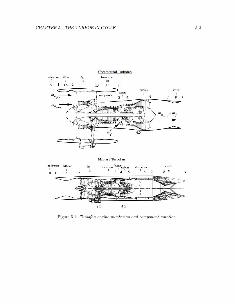
Figure 5.1 illustrates two generic turbofan engine designs. The upper figure shows a modernhigh bypass ratio engine designed for long distance cruise at subsonic Mach numbers around0.83 typical of a commercial aircraft. The fan utilizes a single stage composed of a largediameter fan (rotor) with wide chord blades followed by a single nozzle stage (stator). Thebypass ratio is 5.8 and the fan pressure ratio is 1.9. The lower figure shows a militaryturbofan designed for high performance at supersonic Mach numbers in the range of 1.1to 1.5. The fan on this engine has three stages with an overall pressure ratio of about 6and a bypass ratio of only about 0.6. One of the goals of this chapter is to understandwhy these engines look so di↵erent in terms the di↵erences in flight condition for whichthey are designed. In this context we will begin to appreciate that the thermodynamic andgas dynamic analysis of these engines defines a continuum of cycles as a function of Machnumber. We had a glimpse of this when we determined that the maximum thrust turbojetis characterized by
⌧cmax thrust =
p⌧�⌧r
. (5.1)
For fixed turbine inlet temperature and altitude, as the Mach number increases the opti-mum compression decreases and at some point it becomes desirable to convert the turbojetto a ramjet. We will see a similar kind of trend emerge for the turbofan where it replacesthe turbojet as the optimum cycle for lower Mach numbers. Superimposed on all this is ahistorical technology trend where, with better materials and cooling schemes, the allowableturbine inlet temperature has increased with time. This tends to lead to an optimum cyclewith higher compression and higher bypass ratio at a given Mach number.
5-1
CHAPTER 5. THE TURBOFAN CYCLE 5-2
Figure 5.1: Turbofan engine numbering and component notation.

CHAPTER 5. THE TURBOFAN CYCLE 5-3
The thrust equation for the turbofan is similar to the usual relation except that it includesthe thrust produced by the fan.
T = macore (Ue � U0
) + mafan (Ue1 � U0
) + mfUe + (Pe � P0
)Ae + (Pe1 � P0
)A1e (5.2)
The total air mass flow is
ma = macore + mafan . (5.3)
The fuel/air ratio is defined in terms of the total air mass flow.
f =mf
ma(5.4)
The bypass fraction is defined as
B =mafan
mafan + macore(5.5)
and the bypass ratio is
� =mafan
macore. (5.6)
Note that
� =B
1�B
B =�
1 + �.
(5.7)
5.2 The ideal turbofan cycle
The ideal turbofan cycle is characterized by the following assumptions

CHAPTER 5. THE TURBOFAN CYCLE 5-4
Pe = P0
Pe1 = P0
(5.8)
and
⇡d = 1
⇡b = 1
⇡n = 1
⇡n1 = 1
(5.9)
and
⇡c = ⌧c�
��1
⇡c1 = ⌧c1�
��1
⇡t = ⌧t�
��1 .
(5.10)
For a fully expanded exhaust the normalized thrust is
T
maa0= M
0
✓
(1�B + f)
✓
Ue
U0
� 1
◆
+B
✓
Ue1
U0
� 1
◆
+ f
◆
(5.11)
or, in terms of the bypass ratio with f << 1,
T
maa0= M
0
✓✓
1
1 + �
◆✓
Ue
U0
� 1
◆
+
✓
�
1 + �
◆✓
Ue1
U0
� 1
◆◆
. (5.12)
5.2.1 The fan bypass stream
First work out the velocity ratio for the fan stream.
Ue1
U0
=Me1
M0
r
Te1
T0
(5.13)

CHAPTER 5. THE TURBOFAN CYCLE 5-5
The exit Mach number is determined from the stagnation pressure.
Pte1 = P0
⇡r⇡c1 = Pe1
✓
1 +� � 1
2Me1
2
◆
���1
(5.14)
Since the nozzle is fully expanded and the fan is assumed to behave isentropically, we canwrite
⌧r⌧c1 =
✓
1 +� � 1
2Me1
2
◆
(5.15)
therefore
Me12
M0
2
=⌧r⌧c1 � 1
⌧r � 1. (5.16)
The exit temperature is determined from the stagnation temperature.
Tte1 = T0
⌧r⌧c1 = Te1
✓
1 +� � 1
2Me1
2
◆
(5.17)
Noting (5.15) we can conclude that for the ideal fan
Te1 = T0
. (5.18)
The exit static temperature is equal to the ambient static temperature. The velocity ratioof the fan stream is
✓
Ue1
U0
◆
2
=⌧r⌧c1 � 1
⌧r � 1. (5.19)
5.2.2 The core stream
The velocity ratio across the core is
Ue
U0
=Me
M0
r
Te
T0
. (5.20)

CHAPTER 5. THE TURBOFAN CYCLE 5-6
The analysis of the stagnation pressure and temperature is exactly the same as for theideal turbojet.
Pte = P0
⇡r⇡c⇡t = Pe
✓
1 +� � 1
2Me
2
◆
���1
(5.21)
Since the nozzle is fully expanded and the compressor and turbine operate ideally the Machnumber ratio is
Me2
M0
2
=⌧r⌧c⌧t � 1
⌧r � 1. (5.22)
The temperature ratio is also determined in the same way in terms of component temper-ature parameters.
Tte = T0
⌧r⌧d⌧c⌧b⌧t⌧n (5.23)
In the ideal turbofan we assume that the di↵user and nozzle flows are adiabatic and so
Tte = T0
⌧r⌧c⌧b⌧t = Te
✓
1 +� � 1
2Me
2
◆
= Te⌧r⌧c⌧t (5.24)
from which is determined
Te
T0
= ⌧b =⌧�⌧r⌧c
. (5.25)
The velocity ratio across the core is
✓
Ue
U0
◆
2
=
✓
⌧r⌧c⌧t � 1
⌧r � 1
◆
⌧�⌧r⌧c
. (5.26)
5.2.3 Turbine-compressor-fan matching
The work taken out of the flow by the high and low pressure turbine is used to drive boththe compressor and the fan.
(macore + mf ) (ht4 � ht5) = macore (ht3 � ht2) + mafan (ht31 � ht2) (5.27)
CHAPTER 5. THE TURBOFAN CYCLE 5-7
Divide (5.27) by maCpT0
and rearrange. The work matching condition for a turbofanis
⌧t = 1� ⌧r⌧�
✓
1�B
1�B + f(⌧c � 1) +
B
1�B + f(⌧c1 � 1)
◆
. (5.28)
The approximation f ⌧ 1 is generally pretty good for a turbofan. Using this approximationthe work matching condition becomes
⌧t = 1� ⌧r⌧�
((⌧c � 1) + � (⌧c1 � 1)) (5.29)
where the bypass ratio � appears for the first time. If the bypass ratio goes to zero thematching condition reduces to the usual turbojet formula.
5.2.4 The fuel/air ratio
The fuel/air ratio is determined from the energy balance across the burner.
mf (hf � ht4) = macore (ht4 � ht3) (5.30)
Divide (5.30) by maCpT0
and rearrange. The result is
f =
✓
1
1 + �
◆
⌧� � ⌧r⌧c⌧f � ⌧�
. (5.31)
5.3 Maximum specific impulse ideal turbofan
The non-dimensionalized specific impulse can be expressed in terms of thrust and fuel/airratio as
Ispg
a0
=
✓
T
mfg
◆✓
g
a0
◆
=
✓
T
maa0
◆✓
1
f
◆
. (5.32)
Substitute (5.12) and (5.31) into (5.32). The result is
Ispg
a0
= M0
✓
⌧f � ⌧�⌧� � ⌧r⌧c
◆✓✓
Ue
U0
� 1
◆
+ �
✓
Ue1
U0
� 1
◆◆
. (5.33)

CHAPTER 5. THE TURBOFAN CYCLE 5-8
The question is: what value of � maximizes the specific impulse? Di↵erentiate (5.33) withrespect to � and note that � appears in (5.29).
@
@�
✓
Ispg
a0
◆
= M0
✓
⌧f � ⌧�⌧� � ⌧r⌧c
◆✓
@
@�
✓
Ue
U0
◆
+
✓
Ue1
U0
� 1
◆◆
= 0 (5.34)
We can write (5.34) as
1
2 (Ue/U0
)
@
@�
✓
Ue
U0
◆
2
+
✓
Ue1
U0
� 1
◆
= 0 (5.35)
or
1
2 (Ue/U0
)
✓
⌧�⌧r � 1
◆
@⌧t@�
= �✓
Ue1
U0
� 1
◆
. (5.36)
Equation (5.36) becomes
1
2 (Ue/U0
)
✓
⌧r (⌧c1 � 1)
⌧r � 1
◆
=
✓
Ue1
U0
� 1
◆
. (5.37)
From (5.19),the expression in parentheses on the left side of (5.37) can be written
1
2 (Ue/U0
)
✓
Ue1
U0
◆
2
� 1
!
=
✓
Ue1
U0
� 1
◆
. (5.38)
Factor the left side of (5.38) and cancel common factors on both sides. The velocitycondition for a maximum impulse ideal turbofan is
✓
Ue1
U0
� 1
◆
= 2
✓
Ue
U0
� 1
◆
. (5.39)
According to this result, for an ideal turbofan one would want to design the turbine suchthat the velocity increment across the fan was twice that across the core in order to achievemaximum specific impulse. Recall that Ue/U0
depends on � through (5.29) (and weaklythough (5.31) which we neglect). The value of � that produces the condition (5.39) corre-sponding to the maximum impulse ideal turbofan is
CHAPTER 5. THE TURBOFAN CYCLE 5-9
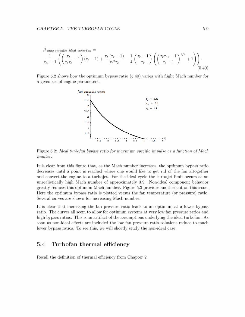
� max impulse ideal turbofan =
1
⌧c1 � 1
✓
⌧�⌧r⌧c
� 1
◆
(⌧c � 1) +⌧� (⌧r � 1)
⌧r2⌧c� 1
4
✓
⌧r � 1
⌧r
◆
✓
⌧r⌧c1 � 1
⌧r � 1
◆
1/2
+ 1
!!
.
(5.40)
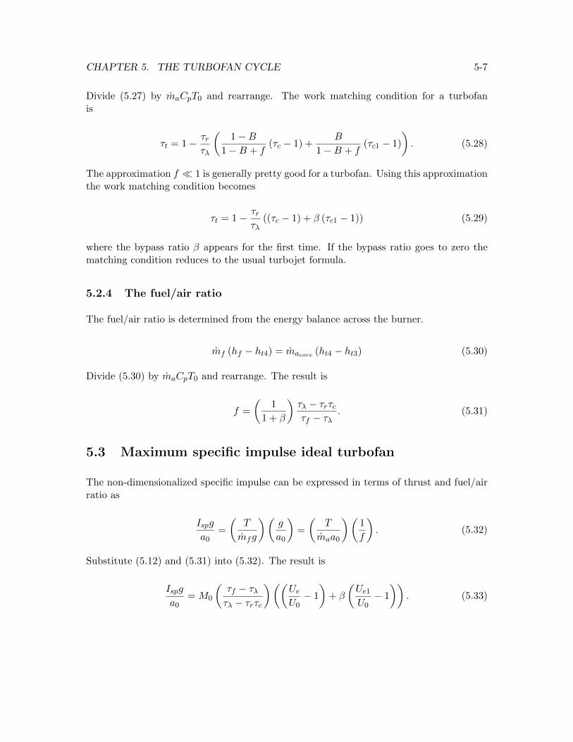
Figure 5.2 shows how the optimum bypass ratio (5.40) varies with flight Mach number fora given set of engine parameters.
Figure 5.2: Ideal turbofan bypass ratio for maximum specific impulse as a function of Machnumber.
It is clear from this figure that, as the Mach number increases, the optimum bypass ratiodecreases until a point is reached where one would like to get rid of the fan altogetherand convert the engine to a turbojet. For the ideal cycle the turbojet limit occurs at anunrealistically high Mach number of approximately 3.9. Non-ideal component behaviorgreatly reduces this optimum Mach number. Figure 5.3 provides another cut on this issue.Here the optimum bypass ratio is plotted versus the fan temperature (or pressure) ratio.Several curves are shown for increasing Mach number.
It is clear that increasing the fan pressure ratio leads to an optimum at a lower bypassratio. The curves all seem to allow for optimum systems at very low fan pressure ratios andhigh bypass ratios. This is an artifact of the assumptions underlying the ideal turbofan. Assoon as non-ideal e↵ects are included the low fan pressure ratio solutions reduce to muchlower bypass ratios. To see this, we will shortly study the non-ideal case.
5.4 Turbofan thermal e�ciency
Recall the definition of thermal e�ciency from Chapter 2.

CHAPTER 5. THE TURBOFAN CYCLE 5-10
Figure 5.3: Ideal turbofan bypass ratio for maximum specific impulse as a function of fantemperature ratio for several Mach numbers.
⌘th =Power to the vehicle+ � kinetic energy of air
second + � kinetic energy of fuelsecond
mfhf(5.41)
For a turbofan with a core and bypass stream the thermal e�ciency is
⌘th =
TU0
+
✓
macore (Ue�U0
)
2
2
+mafan (Ue1�U
0
)
2
2
◆
+⇣
mf (Ue�U0
)
2
2
� mf (U0
)
2
2
⌘
mfhf. (5.42)
Remember, the frame of reference for Equation (5.42) is one where the air ahead of theengine is at rest. If both exhausts are fully expanded, so that Pe = P
0
; Pe1 = P0
thethermal e�ciency becomes
⌘th =
�
macore (Ue � U0
) + mafan (Ue1 � U0
) + mfUe�
U0
mfhf+
✓
macore (Ue�U0
)
2
2
+mafan (Ue1�U
0
)
2
2
◆
+⇣
mf (Ue�U0
)
2
2
� mf (U0
)
2
2
⌘
mfhf
(5.43)
which reduces to
⌘th =
⇣
macore
⇣
Ue2
2
� U0
2
2
⌘
+ mafan
⇣
Ue12
2
� U0
2
2
⌘
+ mfUe
2
2
⌘
U0
mfhf. (5.44)

CHAPTER 5. THE TURBOFAN CYCLE 5-11
We can recast (5.44) in terms of enthalpies using the following relations
mf (hf � ht4) = macore (ht4 � ht3)
ht5 = he +Ue
2
2
ht31 = he1 +Ue1
2
2
(5.45)
where the fan and core nozzle streams are assumed to be adiabatic. Now
⌘th =macore ((ht5 � he)� (ht0 � h
0
)) + mafan ((ht31 � h1e)� (ht0 � h
0
)) + mf (ht5 � he)
(mf + macore)ht4 � macoreht3.
(5.46)
Rearrange (5.46) to read
⌘th =(macore + mf )ht5 + mafanht31 �
�
macore + mafan
�
ht0(mf + macore)ht4 � macoreht3
�
macore (he � h0
) + mafan (he1 � h0
) + mfhe(mf + macore)ht4 � macoreht3
.
(5.47)
Recall the turbofan work balance (5.27). This relation can be rearranged to read
(mf + macore)ht4 � macoreht3 = (macore + mf )ht5 + mafanht31 ��
macore + mafan
�
ht0(5.48)
where it has been assumed that the inlet is adiabatic ht2 = ht0. Now use (5.48) to replacethe numerator or denominator in the first term of (5.47). The thermal e�ciency finallyreads
⌘th = 1�Qrejected during the cycle
Qinput during the cycle= 1�
(macore + mf ) (he � h0
) + mafan (he1 � h0
) + mfh0(mf + macore)ht4 � macoreht3
.
(5.49)
The expression in (5.49) for the heat rejected during the cycle
CHAPTER 5. THE TURBOFAN CYCLE 5-12
Qrejected during the cycle = (macore + mf ) (he � h0
) + mafan (he1 � h0
) + mfh0 (5.50)
brings to mind the discussion of thermal e�ciency in Chapter 2. The heat rejected com-prises heat conduction to the surrounding atmosphere from the fan and core mass flowsplus physical removal from the thermally equilibrated nozzle flow of a portion equal to theadded fuel mass flow. From this perspective the added fuel mass carries its fuel enthalpyinto the system and the exhausted fuel mass carries its ambient enthalpy out of the systemand there is no net mass increase or decrease to the system.
The main assumptions underlying (5.49) are that the engine operates adiabatically, theshaft mechanical e�ciency is one, and the burner combustion e�ciency is one. Engine com-ponents are not assumed to operate ideally; They are not assumed to be isentropic.
5.4.1 Thermal e�ciency of the ideal turbofan
For the ideal cycle, assuming constant Cp, equation (5.49) in terms of temperatures be-comes
⌘thideal turbofan= 1�
✓
(1 + (1 + �) f)Te � T0
(1 + (1 + �) f)Tt4 � Tt3
◆
= 1�✓
1
⌧r⌧c
◆
(1 + (1 + �) f) TeT0
� 1
(1 + (1 + �) f) ⌧�⌧r⌧c
� 1
!
.
(5.51)
Using (5.25) Equation (5.51) becomes
⌘th ideal turbofan= 1�
✓
1
⌧r⌧c
◆
(5.52)
which is identical to the thermal e�ciency of the ideal turbojet. Notice that for the idealturbofan with
he1 = h0
the heat rejected by the fan stream is zero. Therefore the thermal e�ciency of the idealturbofan is independent of the parameters of the fan stream.
5.5 The non-ideal turbofan
The fan, compressor and turbine polytropic relations are

CHAPTER 5. THE TURBOFAN CYCLE 5-13
⇡c1 = ⌧c1�⌘pc1��1
⇡c = ⌧c�⌘pc��1
⇡t = ⌧t�
(��1)⌘pe
(5.53)
where ⌘pc1 is the polytropic e�ciency of the fan. The polytropic e�ciencies ⌘pc, ⌘pc1 and⌘pe are all less than one. The inlet, burner and nozzles all operate with some stagnationpressure loss.
⇡d < 1
⇡n1 < 1
⇡n < 1
⇡b < 1
(5.54)
5.5.1 Non-ideal fan stream
The stagnation pressure ratio across the fan is
Pte1 = P0
⇡r⇡d⇡c1⇡n1 = Pe1
✓
1 +� � 1
2Me1
2
◆
���1
. (5.55)
The fan nozzle is still assumed to be fully expanded and so the Mach number ratio for thenon-ideal turbofan is
✓
Me1
M0
◆
2
=⌧r⌧c1⌘pc1(⇡d⇡n1)
��1
� � 1
⌧r � 1. (5.56)
The stagnation temperature is (assuming the inlet and fan nozzle are adiabatic)
Tte1 = T0
⌧r⌧c1 = Te1
✓
1 +� � 1
2Me1
2
◆
= Te1⌧r⌧c1⌘pc1(⇡d⇡n1)
��1
� (5.57)
and
CHAPTER 5. THE TURBOFAN CYCLE 5-14
Te1
T0
=⌧c11�⌘pc1
(⇡d⇡n1)��1
�
. (5.58)
Now the velocity ratio across the non-ideal fan is
✓
Ue1
U0
◆
2
=1
⌧r � 1
⌧r⌧c1 �⌧c11�⌘pc1
(⇡d⇡n1)��1
�
!
. (5.59)
5.5.2 Non-ideal core stream
The stagnation pressure across the core is
Pte1 = P0
⇡r⇡d⇡c⇡b⇡t⇡n = Pe
✓
1 +� � 1
2Me
2
◆
���1
. (5.60)
The core nozzle is fully expanded and so the Mach number ratio across the non-ideal coreis
✓
Me
M0
◆
2
=⌧r⌧c⌘pc⌧t
1
⌘pe (⇡d⇡b⇡n)��1
� � 1
⌧r � 1. (5.61)
In the non-ideal turbofan we continue to assume that the di↵user and nozzle flows areadiabatic and so
Tte = Te⌧r⌧c⌘pc⌧t
1
⌘pe (⇡d⇡b⇡n)��1
� (5.62)
from which is determined
Te
T0
=⌧c1�⌘pc⌧t
⇣1� 1
⌘pe
⌘
⌧�
⌧r⌧c(⇡d⇡b⇡n)��1
�
. (5.63)
The velocity ratio across the non-ideal core is
✓
Ue
U0
◆
2
=1
⌧r � 1
0
@⌧�⌧t �⌧c1�⌘pc⌧t
⇣1� 1
⌘pe
⌘
⌧�
⌧r⌧c(⇡d⇡b⇡n)��1
�
1
A . (5.64)
CHAPTER 5. THE TURBOFAN CYCLE 5-15
The work balance across the engine remains essentially the same as in the ideal cycle
⌧t = 1� ⌧r⌘m⌧�
((⌧c � 1) + � (⌧c1 � 1)) (5.65)
where the shaft mechanical e�ciency is defined as
⌘m =macore (ht3 � ht2) + mafan (ht31 � ht2)
(mf + macore) (ht4 � ht5). (5.66)
5.5.3 Maximum specific impulse non-ideal cycle
Equation (5.35) remains the same as for the ideal cycle.
1
2 (Ue/U0
)
@
@�
✓
Ue
U0
◆
2
+
✓
Ue1
U0
� 1
◆
= 0 (5.67)
The derivative is
@
@�
✓
Ue2
U0
2
◆
=�⌧r (⌧c1 � 1)
⌘m (⌧r � 1)
0
B
@
1�
⇣
1� 1
⌘pe
⌘
⌧c1�⌘pc⌧t
⇣� 1
⌘pe
⌘
⌧r⌧c(⇡d⇡b⇡n)��1
�
1
C
A
(5.68)
Equations (5.59), (5.64), (5.65) and (5.68) are inserted into (5.67) and the optimal bypassratio for a set of selected engine parameters is determined implicitly. A typical numericallydetermined result is shown in Figure 5.4 and Figure 5.5.
These figures illustrate the strong dependence of the optimum bypass ratio on the non-ideal behavior of the engine. As the losses increase, the bypass ratio optimizes at a lowervalue. But note that the optimum bypass ratio of the non-ideal engine is still somewhathigher than the values generally used in real engines. The reason for this is that ouranalysis does not include the optimization issues connected to integrating the engine ontoan aircraft where there is a premium on designing to a low frontal area so as to reduce dragwhile maintaining a certain clearance between the engine and the runway. Nevertheless,our analysis helps us to understand the historical trend toward higher bypass enginesas turbine and fan e�ciencies have improved along with increases in the turbine inlettemperature.

CHAPTER 5. THE TURBOFAN CYCLE 5-16
Figure 5.4: Turbofan bypass ratio for maximum specific impulse as a function of fan tem-perature ratio comparing the ideal with a non-ideal cycle. Parameters of the non-idealcycle are ⇡d = 0.95, ⌘pc1 = 0.86, ⇡n1 = 0.96, ⌘pc = 0.86, ⇡b = 0.95, ⌘m = 0.98, ⌘pe = 0.86,⇡n = 0.96.
Figure 5.5: Turbofan bypass ratio for maximum specific impulse as a function of Machnumbers comparing the ideal with a non-ideal cycle. Parameters of the non-ideal cycleare ⇡d = 0.95, ⌘pc1 = 0.86, ⇡n1 = 0.96, ⌘pc = 0.86, ⇡b = 0.95, ⌘m = 0.98, ⌘pe = 0.86,⇡n = 0.96.

CHAPTER 5. THE TURBOFAN CYCLE 5-17
5.6 Problems
Problem 1 - Assume � = 1.4, R = 287m2/�
sec2 �K�
, Cp = 1005m2/�
sec2 �K�
. Thefuel heating value is 4.28 ⇥ 107 J/kg. Where appropriate assume f ⌧ 1. The ambienttemperature and pressure are T
0
= 216K and P0
= 2 ⇥ 104N/m2. Consider a turbofanwith the following characteristics.
M0
= 0.85
⌧� = 8.0
⇡c = 30
⇡c1 = 1.6
� = 5
(5.69)
The compressor, fan and turbine polytropic e�ciencies are
⌘pc = 0.9
⌘pc1 = 0.9
⌘pt = 0.95.
(5.70)
Let the burner e�ciency and pressure ratio be ⌘b = 0.99 and ⇡b = 0.97. Assume the shafte�ciency is one. Both the fan and core streams use ideal simple convergent nozzles. De-termine the dimensionless thrust T/P
0
A0
, specific fuel consumption, and overall e�ciencyof the engine. Suppose the engine is expected to deliver 8,000 pounds of thrust at cruiseconditions. What must be the area of the fan face A
2
?
Problem 2 - Use Matlab or Mathematica to develop a program that reproduces Figure5.4 and Figure 5.5.
Problem 3 - Figure 5.6 shows an ideal turbofan operating with a heat exchanger at itsaft end.
The heat exchanger causes a certain amount of thermal energy Q (Joules/sec) to be trans-ferred from the hot core stream to the cooler fan stream. Let the subscript x refer to theheat exchanger. Assume that the heat exchanger operates without any loss of stagnationpressure ⇡x = ⇡x1 = 1 and that both nozzles are fully expanded. Let ⌧x = Tte/Tt5 and⌧x1 = Tte1/Tt51. The thrust is given by

CHAPTER 5. THE TURBOFAN CYCLE 5-18
Figure 5.6: Turbofan with an aft heat exchanger.
T
macorea0= M
0
✓✓
Ue
U0
� 1
◆
+ �
✓
Ue1
U0
� 1
◆◆
(5.71)
where we have assumed f ⌧ 1.
1) Derive an expression for T/ (macorea0) in terms of ⌧�, ⌧r, ⌧c, ⌧c1, � and ⌧x, ⌧x1.
2) Write down an energy balance between the core and fan streams. Suppose an amountof heat Q is exchanged. Let ⌧x = 1�↵ where ↵ = Q/macoreCpTt5, Q > 0. Show that
⌧x1 = 1 +
✓
⌧�⌧t�⌧r⌧c1
◆
↵. (5.72)
3) Consider an ideal turbofan with the following characteristics.
T0
= 216K
M0
= 0.85
⌧� = 7.5
⇡c = 30
⇡c1 = 1.6
� = 5
(5.73)
CHAPTER 5. THE TURBOFAN CYCLE 5-19
Plot T/macorea0 versus ↵ for 0 < ↵ < ↵max
where ↵max
corresponds to the value of ↵ suchthat the two streams are brought to the same stagnation temperature coming out of theheat exchanger.
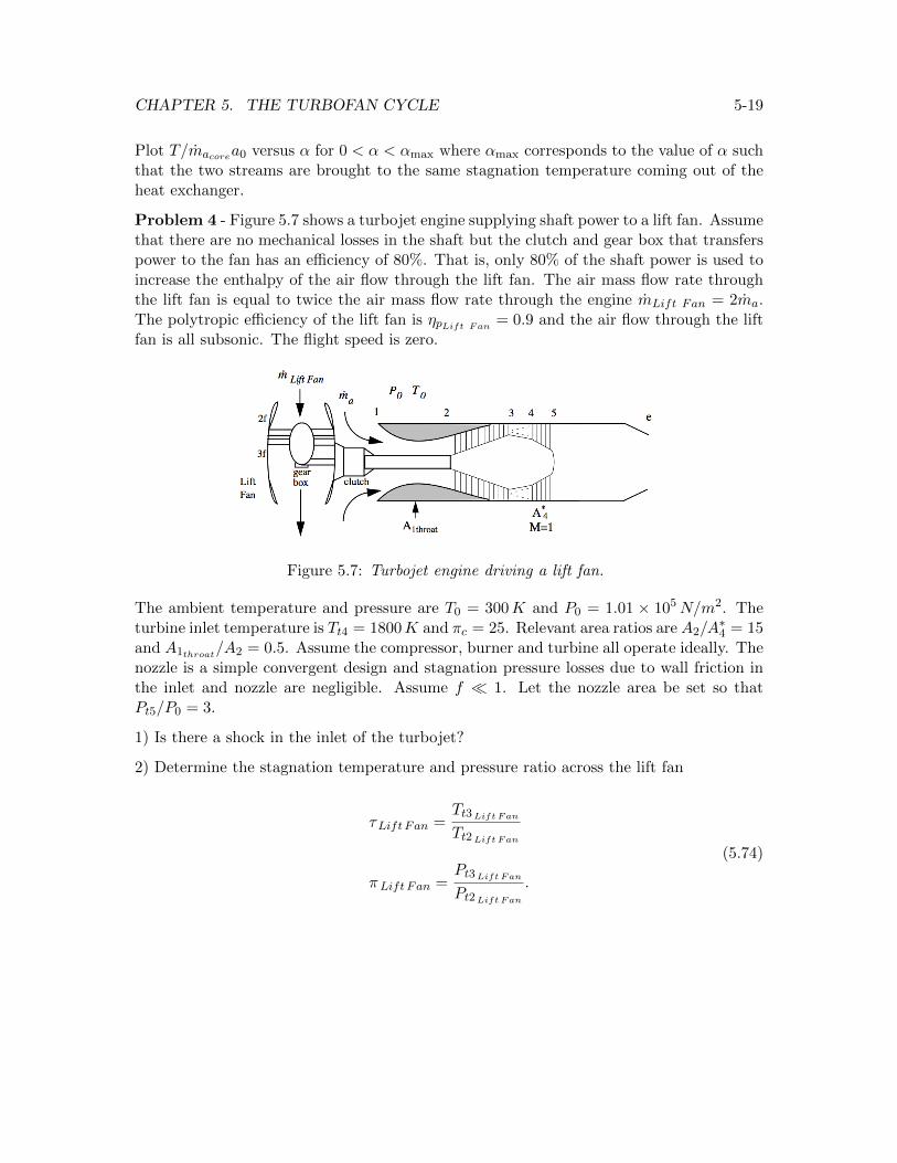
Problem 4 - Figure 5.7 shows a turbojet engine supplying shaft power to a lift fan. Assumethat there are no mechanical losses in the shaft but the clutch and gear box that transferspower to the fan has an e�ciency of 80%. That is, only 80% of the shaft power is used toincrease the enthalpy of the air flow through the lift fan. The air mass flow rate throughthe lift fan is equal to twice the air mass flow rate through the engine mLift Fan = 2ma.The polytropic e�ciency of the lift fan is ⌘pLift Fan = 0.9 and the air flow through the liftfan is all subsonic. The flight speed is zero.
Figure 5.7: Turbojet engine driving a lift fan.
The ambient temperature and pressure are T0
= 300K and P0
= 1.01 ⇥ 105N/m2. Theturbine inlet temperature is Tt4 = 1800K and ⇡c = 25. Relevant area ratios are A
2
/A⇤4
= 15and A
1throat/A2
= 0.5. Assume the compressor, burner and turbine all operate ideally. Thenozzle is a simple convergent design and stagnation pressure losses due to wall friction inthe inlet and nozzle are negligible. Assume f ⌧ 1. Let the nozzle area be set so thatPt5/P0
= 3.
1) Is there a shock in the inlet of the turbojet?
2) Determine the stagnation temperature and pressure ratio across the lift fan
⌧Lift Fan =Tt3Lift Fan
Tt2Lift Fan
⇡Lift Fan =Pt3Lift Fan
Pt2Lift Fan
.
(5.74)