the tradeoff between solar reflectance and above- sheathing ventilation ... · ornl/tm-2011/x the...
TRANSCRIPT
ORNL/TM-2011/X
The Tradeoff Between Solar Reflectance and Above-Sheathing Ventilation for Metal Roofs on Residential and
Commercial Buildings
William A. Miller, Ph.D.
Ethan Herman
Russell Graves
January 2012
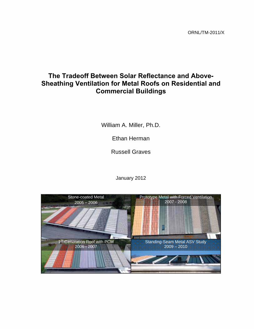
Stone-coated Metal 2005 - 2006
Prototype Metal with Forced Ventilation 2007 - 2008
1St Generation Roof with PCM 2006 - 2007
Standing-Seam Metal ASV Study 2009 – 2010
DOCUMENT AVAILABILITY
Reports produced after January 1, 1996, are generally available free via the U.S. Department of Energy (DOE) Information Bridge:
Web site: http://www.osti.gov/bridge Reports produced before January 1, 1996, may be purchased by members of the public from the following source:
National Technical Information Service 5285 Port Royal Road Springfield, VA 22161 Telephone: 703-605-6000 (1-800-553-6847) TDD: 703-487-4639 Fax: 703-605-6900 E-mail: [email protected] Web site: http://www.ntis.gov/support/ordernowabout.htm
Reports are available to DOE employees, DOE contractors, Energy Technology Data Exchange (ETDE) representatives, and International Nuclear Information System (INIS) representatives from the following source:
Office of Scientific and Technical Information P.O. Box 62 Oak Ridge, TN 37831 Telephone: 865-576-8401 Fax: 865-576-5728 E-mail: [email protected] Web site: http://www.osti.gov/contact.html
This report was prepared as an account of work sponsored by an agency of the United States government. Neither the United States government nor any agency thereof, nor any of their employees, makes any warranty, express or implied, or assumes any legal liability or responsibility for the accuracy, completeness, or usefulness of any information, apparatus, product, or process disclosed, or represents that its use would not infringe privately owned rights. Reference herein to any specific commercial product, process, or service by trade name, trademark, manufacturer, or otherwise, does not necessarily constitute or imply its endorsement, recommendation, or favoring by the United States government or any agency thereof. The views and opinions of authors expressed herein do not necessarily state or reflect those of the United States government or any agency thereof.

ORNL/TM-2011/X
The Tradeoff Between Solar Reflectance and Above-Sheathing Ventilation for Metal Roofs on Residential and Commercial Buildings
William A. Miller, Ph.D. Building Envelopes Program
Oak Ridge National Laboratory
Ethan Herman Russell Graves
University of Tennessee MABE Students
January 2012
Prepared for the U.S. Department of Energy Buildings Technology Program
Marc LaFrance, Program Manager and the
Metal Construction Association
Prepared by OAK RIDGE NATIONAL LABORATORY
P.O. Box 2008 Oak Ridge, Tennessee 37831-6283
managed by UT-Battelle, LLC
for the U.S. DEPARTMENT OF ENERGY
under contract DE-AC05-00OR22725

iii
CONTENTS
CONTENTS ......................................................................................................................................................... III ABSTRACT .......................................................................................................................................................... V ACKNOWLEDGMENTS .................................................................................................................................... VI ABBREVIATIONS, NOMENCLATURE, AND SUBSCRIPTS ...................................................................... VII EXECUTIVE SUMMARY .................................................................................................................................... 9 1. INTRODUCTION ........................................................................................................................................... 11 2. ABOVE-SHEATHING VENTILATION ― FIELD DATA .......................................................................... 11
2.1 Solar Reflectance and Thermal Emittance ............................................................................................... 13 2.1.1 Effects of Climatic Soiling ............................................................................................................. 13
2.2 Stone-Coated Metal .................................................................................................................................. 15 2.3 Standing-Seam Metal ............................................................................................................................... 16
2.3.1 Winter Field Tests .......................................................................................................................... 17 2.4 Airflow Measurements Using Tracer Gas Techniques ..................................................................... 19 2.5 Validation of ASV Algorithm ........................................................................................................... 20 2.6 Effective R-Value of the Inclined Air Space..................................................................................... 20
3. METHODOLOGY USED FOR SR AND ASV TRADEOFF ........................................................................ 23 3.1 AtticSim Computer Tool .......................................................................................................................... 24 3.2 Tasks Required to Judge the SR Tradeoff with ASV ............................................................................... 25
3.2.1 TASK 1A: Determine SR needed for steep-slope (18.4°) roof with ASV (minimum ¾ in. of continuous air gap) to match load of an SR-0.25 (0.15 weathered) cool roof fastened directly to deck .......................................................................................................... 26
3.2.2 TASK 1B: Determine the SR needed in a steep-slope roof with ASV (minimum ¾ in. of continuous air gap) to match load of an SR-0.40 roof (0.25 weathered) fastened directly to deck .......................................................................................................... 29
3.2.3 TASK 1C: Determine the SR needed in a low-slope (9.5°) roof with ASV to match load of an SR-0.65 (0.50 weathered) cool roof fastened directly to deck ................................... 30
3.2.4 TASK 2: Determine SR needed for a steep-slope (18.4°) direct-to-deck roof to match load of a cool roof with ASV .................................................................................................... 31
3.2.5 TASK 3: Determine SR needed for a low-slope (9.5°) direct-to-deck roof to match load of an SR-0.65 (0.50 weathered) cool roof with ASV .......................................................... 34
4. CONCLUSIONS ............................................................................................................................................. 35 5. RECOMMENDATIONS ................................................................................................................................ 37 6. REFERENCES ................................................................................................................................................ 38 APPENDIX A: SEASONAL LOADS COMPUTED FOR TASK 1 .................................................................. 41 APPENDIX B: SEASONAL LOADS COMPUTED FOR TASK 2 ................................................................... 43 APPENDIX C: SEASONAL LOADS COMPUTED FOR TASK 3 ................................................................... 45

iv

v
ABSTRACT Cool roofs have received much positive trade press, and some state and federal support for installations where comfort cooling is the dominant building energy load. In mixed climates with both significant heating and cooling loads, the wintertime effect reduces the energy benefit because the desirable roof heat gain in winter is diminished somewhat by the higher solar reflectance of the roof. Field data show that metal roofs that are elevated off the roof deck and that exploit the use of cool color pigments provide an excellent design strategy for reducing roof heat gains and losses. The design improves the durability of the roof assembly because the natural convection ventilation helps to dry the deck of moisture. It can also protect the roof from wildfires common in wildlife-urban environmental interfaces. The thermally induced bouyant flow increases as the metal’s temperature increases. Therefore intense heat is not conducted directly through the metal to the wood sheathing, and ignition is delayed if not eliminated from the system. An alternative approach to white and cool color roofs was documented that meets prescriptive requirements for steep-slope residential and non-residential roofing. The approach computed equal heat fluxes through the ceilings of roofs having different combinations of surface radiation properties and or building constructions. A painted metal roof with 0.75-in (0.019-m) air space needs only a 0.10 solar reflectance to have the same annual cooling load as a direct-to-deck cool color metal roof for the eight ASHRAE climate zones investigated in this report. A roof fitted with a 1.5-in (0.038-m) inclined air space above the roof deck can be black and still have a seasonal cooling load that matches the conventionally constructed cool color (solar reflectance of 0.25) metal roof. Computations for retrofit application based on ASHRAE 90 (1980) show ASV air spaces of 0.75- and 1.5-in (0.019- and 0.038-m) would permit black roofs to have cooling loads equivalent to the direct to deck cool roof.

ACKNOWLEDGMENTS Funding for this project was provided by the U.S. Department of Energy under the direction of Marc LaFrance of the Buildings Program. The cool roof project team members are André Desjarlais, Dr. William Miller, and Kaushik Biswas, all of ORNL’s Buildings Technology Research Integration Center. Dr. Tom Petrie, who formerly worked with this team, is deseased, and his presence, professionalism, and contributions are missed by all who worked with him. The Metal Construction Association and its affiliate members provided the stone-coated shake and S-mission roofs. Metro Roof Products constructed the attic assemblies and provided valuble assistance in installing the roofs on the steep-slope assemblies. Custom-Bilt Metals provided the cool-color standing-seam metal roofs. The financial support of the Metal Construction Association and the guidance of Metro Roof Products and Custom-Bilt Metals is greatly appreciated.

vii
ABBREVIATIONS, NOMENCLATURE, AND SUBSCRIPTS
Abbreviations ASTM American Society for Testing and Materials ASV Above-sheathing ventilation BTRIC Buildings Technology Research Integration Center (ORNL) DOE U.S. Department of Energy ESRA Envelope Systems Research Apparatus HFT Heat flux transducer MCA Metal Construction Association ORNL Oak Ridge National Laboratory OSB Oriented strand board PVDF Polyvinylidene fluoride
Nomenclature ε or E thermal emittance RUS thermal resistance (hr ⋅ft2⋅oF/Btu) ρ or SR solar reflectance RSI thermal resistance (m2⋅oC/W)
C concentration of CO2 (ppmv) V volume of inclined channel
Cp specific heat Vol volume
CDD cooling degree days based on 65°F V& volumetric flow rate (cfm) HDD heating degree days based on 65°F σ Stefan-Boltzmann constant
h convective coefficient (Btu/hr⋅ft2⋅°F) k thermal conductivity (Btu/hr⋅ft⋅°F)
θ roof slope T temperature t time (s)
Subscripts
abs absorbed heat
air air within inclined channel
sky sky temperature
S roof surface
channel inclined air gap made by roof and sheathing
IR infrared spectrum
solar irradiance
∞ outdoor ambient

viii

EXECUTIVE SUMMARY
Several steep-slope roofs and attics were installed on top of the Envelope Systems Research Apparatus (ESRA) at Oak Ridge National Laboratory (ORNL) for field-testing of stone-coated metal and standing-seam metal roofs. All roofs were equipped with ridge and soffit vents for ventilating the attic. The ratio of the vent opening area to attic floor area was 1 to 300. The stone-coated metal and standing-seam metal roofs were either offset-mounted or directly nailed to the roof deck. The offset mounting was accomplished using double-batten construction for stone-coated metal shakes and using variable-height clips for standing-seam metal roofs. The inclined air space formed by the offset between the roof deck and metal roofing material provided a ventilation path for the redirection of solar heat away from the attic.
The objective of this project was to use the field data to formulate and validate AtticSim [i.e., ASTM protocol C-1340 (ASTM 2004) and exercise the code to document the tradeoff between the solar reflectance of cool-color roofs and the benefit of providing above-sheathing ventilation (ASV) through an inclined air space above the roof deck. The goal was to corroborate the equivalent energy saving benefits of a roof constructed with ASV as compared to a 0.25- solar reflective (0.15 weathered) roof attached directly to the roof deck, without ASV. Miller et al. (2007) formulated and then validated an algorithm for ASV, and benchmarked C-1340 (ASTM 2004) against data for both the stone-coated metal and standing-seam metal roofs.
Whole-house simulations were made using ASTM C-1340 (ASTM 2004) coupled to Energy Plus. Energy Plus modeled the Building Energy Simulation Test (BESTEST) home (NREL 1995) and estimated the hourly indoor air temperature and hourly run times for a SEER 13 air conditioner as it cooled the home. An 85% efficient gas furnace heated the home. The Home Energy Rating System (HERS) uses the BESTEST home as a standard to evaluate the credibility of software to accurately model residential energy use (NREL 1995). Hourly values of the airflow and the bulk air temperature entering the different sections of the duct, the percentage on time of the HVAC, and the indoor air temperature were written to auxiliary files and read by ASTM C-1340 for computing the roof and attic load as coupled to the BESTEST home simulated in the various ASHRAE climate zones. Simulations of low-slope roof configurations assumed the HVAC system and ductwork were in the conditioned space.
An alternative approach to prescriptive cool roof requirements is documented for steep-slope residential and non-residential roofing. The approach computed equal heat fluxes through the ceilings of roofs having different combinations of surface radiation properties and/or building constructions. The results are reported in Tasks 1 through 3 in the body of the report. In hot climates, a painted standing-seam metal roof with 0.75 in. (0.019 m) air space needs only a solar reflectance of 0.10 to have the same annual cooling load as a direct-to-deck cool-color metal roof with fresh solar reflectance of 0.25.
Solar reflectance needed by an offset-mounted metal roof to match the cooling load of a cool metal roof (0.25 solar reflectance) fastened directly to the roof deck.

In the colder climates a solar reflectance of only 0.065 is needed to have the same seasonal cooling load as a direct-to-deck cool metal roof. A roof fitted with 1.5 in. (0.038 m) of ASV can be almost black and still have a seasonal cooling load within 0.05% of the conventionally constructed cool-color metal roof (solar reflectance 0.25 new, 0.15 aged). Results for the standing-seam metal and for the stone-coated metals show that both can be effectively black and still have cooling loads equivalent to the cool-color roof fastened directly to to the roof deck.
The hot climates of Miami, Austin, and Atlanta require solar reflectances of 0.29, 0.28 and 0.26, respectively, for an offset-mounted-roof with[0.75 in. (0.019 m) ASV to have the same seasonal cooling load as the 0.40 solar reflective direct-to-deck metal roof. Offsetting the standing-seam metal by 1.5 in. (38 mm) further drops the solar reflectance needed to match the cooling load of a cool metal fastened directly to the deck. Stone-coated metal roofs that are offset 0.75 in. (0.019 m) can have a solar reflectance of about 0.17 in Miami, 0.16 in Austin and 0.10 in Atlanta and still match the seasonal cooling load of the base cool metal (SR 0.40) roof fastened directly to the deck. A spacing of 1.5 in. (38 mm), which is conventional practice for stone-coated metal installed on double battens, can have a solar reflectance on the order 0.10 and still yield the same seasonal cooling load as the 0.40 solar reflective metal roof fastened directly to the deck.
Solar reflectance needed for an offset-mounted metal roof to match the cooling load for a 0.40 solar reflective roof fastened directly to the roof deck (D-t-D).
1. INTRODUCTION
In moderate and hot climates, a roof surface with high solar reflectance and high thermal emittance was shown by Akbari et al. (2004) and by Parker and Sherwin (1998) to reduce the exterior temperature and produce savings in comfort cooling. Akbari and Levinson (2008) made a compilation of cool roof studies conducted for non-residential low-slope buildings. They observed summertime daily air-conditioning savings and peak demand reductions ranging from about 10 to 30%, though some reported data showed values as low as 2% and as high as 40%. The findings clearly show that cool roofs can be a viable strategy for reducing energy consumption, and therefore many U.S. states have implemented prescriptive requirements for cool roofs in their energy codes based on ASHRAE Standard 90.1 (2007a), ASHRAE Standard 90.2 (2007b), or the International Energy Conservation Code (IECC2009), or have developed custom provisions.
California’s building code regulations, referred to here as 2008 Title 24, specify either a performance or a prescriptive approach for demonstrating the energy-efficiency compliance of buildings in California (CEC 2008). The performance approach allows the building owner to simulate the energy usage of a proposed building using an approved whole-building model. Alternatively, the prescriptive approach requires that each building component meet or surpass the respective component requirements in 2008 Title 24, which prescribes the initial solar reflectance (SR) of steep-slope residential and nonresidential cool roofs. Aged solar reflectance must equal 0.15 and emittance must be greater than or equal to 0.75.
The U.S. Environmental Protection Agency (EPA) has similar guidelines for its Energy Star certification but does not presently regulate the value for thermal emittance. Energy Star-labeled cool roofs used in a steep slope application must meet an initial SR of 0.25 and after 3 years of exposure have a soiled SR of at least 0.15. \
While industry concurs with many of the cool roof guidelines, there is concern among roof manufacturers that the strong emphasis on cool roof guidelines ignores other viable construction practices. Roofs fitted with an inclined air space above the sheathing (above-sheathing ventilation, or ASV), roofs fitted with radiant barriers, and roofs fitted with added insulation above minimal code perform as well as if not better than high-reflectance, high-emittance roofs.
Therefore this report presents an alternative approach to meeting prescriptive requirements for steep-slope residential and non-residential roofs. Equal heat fluxes from the attic through the ceiling in houses with roofs having different combinations of surface radiation properties and/or having different building configurations are required. The goal is to show how roofs fitted with an inclined air space above the roof deck can meet prescriptions for cool roofs regulated by the 2008 Title 24 code and the EPA Energy Star program in ASHRAE’s eight climate zones.
2. ABOVE-SHEATHING VENTILATION ― FIELD DATA
The venting of the underside of a roof cover provides thermal benefits for comfort heating and cooling. Residential roof tests by Beal and Chandra (1995) demonstrated a 45% reduction in the daytime heat flux penetrating a counter-batten tile roof as compared to a direct-nailed shingle roof. Parker, Sonne, and Sherwin (2002) observed in their study that a barrel-shaped terra-cotta tile with moderate solar reflectance reduced the home’s annual cooling load by about 8% of the base load measured for an identical adjacent home with an asphalt shingle roof. These reported energy savings are in part attributed to a thermally driven airflow within an inclined air space formed by the underside of the roof and the roof’s deck, or above-sheathing ventilation (ASV), which is the direct result of buoyancy and to some extent wind forces. The air space provides some improvement in the insulating effect of the roofing system. ASHRAE (2005) provides empirical data for the effective thermal resistance of plane air spaces. A ¾ in. (0.0191 m) plane air space inclined at 45° from the horizontal has an insulation value of RUS-0.85 (RSI-0.15)1. Note, however, that the ASHRAE data is based on
1 An effective emittance of 0.82 was assumed with a mean temperature of 90°F (32.2°C) having a 10°F (5.6°C) temperature gradient for heat flows moving downward across the air space.
empirical data and correlations for a closed air space. In conventional construction the air space is often open, implying that the ASHRAE values are conservative.
The heat transfer in the air space can switch from conduction to single-cell convection to Bénard cell convection depending on the aspect ratio made by the underside of the roof and the roof deck, the slope of the roof, and the weather. Experimental measurements and numerical simulations are required to model and accurately predict the coexistence and competition between the various modes of heat transfer observed in ASV. Therefore, this research used a combined experimental and analytical approachd, with several years of field data collected that included summer and winter exposure of stone-coated metal and standing-seam metal products applied directly to the deck and offset from the roof deck.
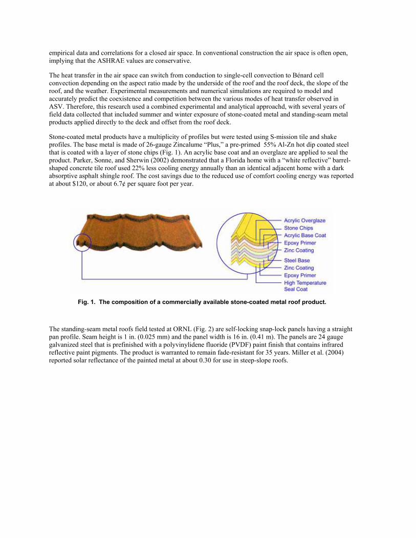
Stone-coated metal products have a multiplicity of profiles but were tested using S-mission tile and shake profiles. The base metal is made of 26-gauge Zincalume “Plus,” a pre-primed 55% Al-Zn hot dip coated steel that is coated with a layer of stone chips (Fig. 1). An acrylic base coat and an overglaze are applied to seal the product. Parker, Sonne, and Sherwin (2002) demonstrated that a Florida home with a “white reflective” barrel-shaped concrete tile roof used 22% less cooling energy annually than an identical adjacent home with a dark absorptive asphalt shingle roof. The cost savings due to the reduced use of comfort cooling energy was reported at about $120, or about 6.7¢ per square foot per year.
Fig. 1. The composition of a commercially available stone-coated metal roof product.
The standing-seam metal roofs field tested at ORNL (Fig. 2) are self-locking snap-lock panels having a straight pan profile. Seam height is 1 in. (0.025 mm) and the panel width is 16 in. (0.41 m). The panels are 24 gauge galvanized steel that is prefinished with a polyvinylidene fluoride (PVDF) paint finish that contains infrared reflective paint pigments. The product is warranted to remain fade-resistant for 35 years. Miller et al. (2004) reported solar reflectance of the painted metal at about 0.30 for use in steep-slope roofs.
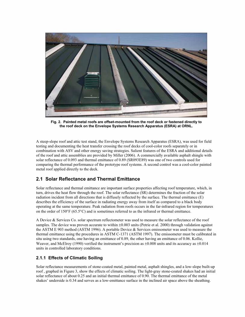
Fig. 2. Painted metal roofs are offset-mounted from the roof deck or fastened directly to the roof deck on the Envelope Systems Research Apparatus (ESRA) at ORNL.
A steep-slope roof and attic test stand, the Envelope Systems Research Apparatus (ESRA), was used for field testing and documenting the heat transfer crossing the roof decks of cool-color roofs separately or in combination with ASV and other energy saving strategies. Salient features of the ESRA and additional details of the roof and attic assemblies are provided by Miller (2006). A commercially available asphalt shingle with solar reflectance of 0.093 and thermal emittance of 0.89 (SR093E89) was one of two controls used for comparing the thermal performance of the prototype roof systems. A second control was a cool-color painted metal roof applied directly to the deck.
2.1 Solar Reflectance and Thermal Emittance
Solar reflectance and thermal emittance are important surface properties affecting roof temperature, which, in turn, drives the heat flow through the roof. The solar reflectance (SR) determines the fraction of the solar radiation incident from all directions that is diffusely reflected by the surface. The thermal emittance (E) describes the efficiency of the surface in radiating energy away from itself as compared to a black body operating at the same temperature. Peak radiation from roofs occurs in the far-infrared region for temperatures on the order of 150°F (65.5°C) and is sometimes referred to as the infrared or thermal emittance.
A Device & Services Co. solar spectrum reflectometer was used to measure the solar reflectance of the roof samples. The device was proven accurate to within ±0.003 units (Petrie et al. 2000) through validation against the ASTM E 903 method (ASTM 1996). A portable Device & Services emissometer was used to measure the thermal emittance using the procedures in ASTM C-1371 (ASTM 1997). The emissometer must be calibrated in situ using two standards, one having an emittance of 0.89, the other having an emittance of 0.06. Kollie, Weaver, and McElroy (1990) verified the instrument’s precision as ±0.008 units and its accuracy as ±0.014 units in controlled laboratory conditions.
2.1.1 Effects of Climatic Soiling
Solar reflectance measurements of stone-coated metal, painted metal, asphalt shingles, and a low-slope built-up roof , graphed in Figure 3, show the effects of climatic soiling. The light-gray stone-coated shakes had an initial solar reflectance of about 0.25 and an initial thermal emittance of 0.90. The thermal emittance of the metal shakes’ underside is 0.34 and serves as a low-emittance surface in the inclined air space above the sheathing.

After 3 years of exposure on ESRA, the light-gray metal shakes showed about a 10% loss in solar reflectance. Losses level off after about 1 year of exposure and remain steady for a year and lessen somewhat after 2 years. The dark-gray metal shake and the conventional asphalt shingle actually show some increase in solar reflectance due to the accumulation of airborne contaminants. Dust tends to lighten a darker color. However, little change in solar reflectance was observed for the low-slope built-up roof exposed on the ESRA. The cool-color shingle showed no noticeable loss in solar reflectance over the 3 year exposure in East Tennessee’s climate.
Fig. 3. Solar reflectance of stone-coated metal, standing seam PVDF metal, asphalt shingle
and low-slope built-up roofs exposed to East Tennessee weather over three years on (ESRA.
Coupons of the stone-coated metal prototypes were also exposed in 7 of the 16 California climate zones (Miller et al. 2010). Many of the California climate zones are arid and have considerable airborne contaminants. Shafter and Sacramento showed a 17% loss in solar reflectance after 3 years of exposure; however, McArthur and Corona showed only a 3% and 7% loss from initial (or fresh) solar reflectance values. In comparison, the solar reflectance of the dark-gray metal shake increased across all climate zones because of the effect of airborne dust accumulating on the samples.
The white painted PVDF metal roofs had less than a 5% loss in solar reflectance (Fig. 3). Berdahl et al. (2006) reported fence post exposures in Florida of PVDF-based metal roof coatings (Fig. 4). A palette of colors were exposed by several manufacturers in south Florida, and the data proved that the PVDF-based coatings are very resistant to climatic soiling as demonstrated by the marginal loss in solar reflectance (less that 5%) incurred for 15–35 year exposures (Miller, Kriner, and Parker 2005).
The data from manufacturers Atofina, Solvay Solexis, Akzo Nobel, and BASF shown in Fig. 4 provide a review of sustained performance for almost 35 years. The reflectance of the Atofina PVDF white metal remains relatively constant even after 35 years of exposure.

Fig. 4. Solar reflectance of PVDF painted metals from manufacturers BASF, Atofina, Akzo Nobel and Solvay Solexis.
2.2 Stone-Coated Metal
Miller, Wilson, and Karagiozis (2006) field tested stone-coated metal roofs on adjacent attic test assemblies on the ESRA. Miller (2006) provides full details of the study; however, a few findings will be reviewed here to highlight the benefits of ASV. A conventional dark-gray stone-coated metal shake (SR08E90) and a light-gray metal shake (SR26E90) were tested on identical double-batten constructions (air space of ¾ in. [0.019 m]). The dark-gray metal shake and the control shingle have almost identical solar reflectance and thermal emittance characteristics, yet the heat flow crossing the roof deck from the dark-gray shake was just 70% of the heat flow crossing the roof deck of the control shingle (Fig. 5). The 30% lower heat flow was caused by the thermal resistance of the air space due to convection occurring in the air space, and in part by the low emittance (0.35) of the underside of the stone-coated roof shake.
Increasing solar reflectance from 0.08 to 0.26 caused the heat flow crossing the roof deck of the light-gray shake to be less than the heat flow crossing the deck of the dark-gray stone-coated shake (Fig. 5). Miller, Wilson, and Karagiozis (2006) also determined that the heat flow removed by ASV of the hotter dark-gray stone-coated shake is more than double that removed by the light-gray shake. The hotter dark-gray stone-coated shake causes greater buoyancy-induced airflows; therefore, the ventilation scheme is somewhat self-regulating. The darker the roof, the hotter the roof, and the greater the buoyant flow that carries heat away from the attic space. The stone-coated metal lacks the mass of a concrete tile, implying that ASV and/or the effective thermal resistance of the air space significantly affect the amount of heat penetrating into the attic. As mentioned, ASHRAE (2005) provides empirical data for the effective thermal resistance of plane and closed air spaces. A ¾ in. (0.0191 m) plane and closed air space inclined at 45° from the horizontal has an insulation value of RUS-0.7 (RSI-0.12). The air space for the metal roofs was ventilated at the eave and the ridge and therefore has a slightly higher thermal resistance, estimated by AtticSim at RUS-2 (RSI-0.36).
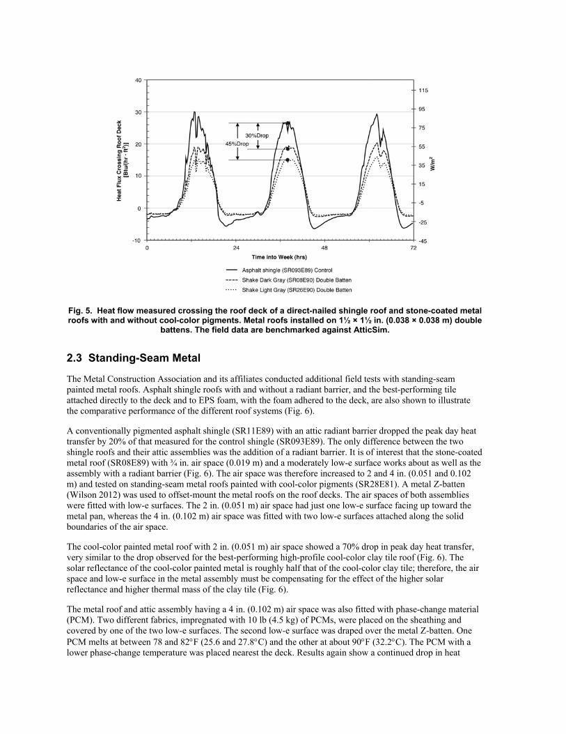
Fig. 5. Heat flow measured crossing the roof deck of a direct-nailed shingle roof and stone-coated metal roofs with and without cool-color pigments. Metal roofs installed on 1½ × 1½ in. (0.038 × 0.038 m) double
battens. The field data are benchmarked against AtticSim.
2.3 Standing-Seam Metal
The Metal Construction Association and its affiliates conducted additional field tests with standing-seam painted metal roofs. Asphalt shingle roofs with and without a radiant barrier, and the best-performing tile attached directly to the deck and to EPS foam, with the foam adhered to the deck, are also shown to illustrate the comparative performance of the different roof systems (Fig. 6).
A conventionally pigmented asphalt shingle (SR11E89) with an attic radiant barrier dropped the peak day heat transfer by 20% of that measured for the control shingle (SR093E89). The only difference between the two shingle roofs and their attic assemblies was the addition of a radiant barrier. It is of interest that the stone-coated metal roof (SR08E89) with ¾ in. air space (0.019 m) and a moderately low-e surface works about as well as the assembly with a radiant barrier (Fig. 6). The air space was therefore increased to 2 and 4 in. (0.051 and 0.102 m) and tested on standing-seam metal roofs painted with cool-color pigments (SR28E81). A metal Z-batten (Wilson 2012) was used to offset-mount the metal roofs on the roof decks. The air spaces of both assemblies were fitted with low-e surfaces. The 2 in. (0.051 m) air space had just one low-e surface facing up toward the metal pan, whereas the 4 in. (0.102 m) air space was fitted with two low-e surfaces attached along the solid boundaries of the air space.
The cool-color painted metal roof with 2 in. (0.051 m) air space showed a 70% drop in peak day heat transfer, very similar to the drop observed for the best-performing high-profile cool-color clay tile roof (Fig. 6). The solar reflectance of the cool-color painted metal is roughly half that of the cool-color clay tile; therefore, the air space and low-e surface in the metal assembly must be compensating for the effect of the higher solar reflectance and higher thermal mass of the clay tile (Fig. 6).
The metal roof and attic assembly having a 4 in. (0.102 m) air space was also fitted with phase-change material (PCM). Two different fabrics, impregnated with 10 lb (4.5 kg) of PCMs, were placed on the sheathing and covered by one of the two low-e surfaces. The second low-e surface was draped over the metal Z-batten. One PCM melts at between 78 and 82°F (25.6 and 27.8°C) and the other at about 90°F (32.2°C). The PCM with a lower phase-change temperature was placed nearest the deck. Results again show a continued drop in heat

transfer crossing the roof deck. Increasing the air space from 2 to 4 in. (0.051 to 0.102 m) and adding PCM caused an additional 10% drop compared with the assembly with a 2 in. air space (Fig. 6). Overall, the peak day heat transfer was reduced by about 90% compared with that measured for the control shingle roof. Further, the performance of the cool-color metal roof with a 4 in. (0.102 m) air space, low-e surfaces, and PCM is almost identical to that of the cool-color clay tile (SR54E90) adhered to EPS foam board with insulating value of RUS-6.25 (RSI-1.1). The attic air temperature of these two roofs never exceeded the peak day outdoor air temperature! During the month of August, the control shingle assembly had attic air temperatures reaching as high as 120°F (48.9°C) when the outdoor air peaked at 96°F (35.6°C). Hence, the two prototype roof and attic assemblies with their lower peak day attic air temperatures (93 versus 120°F [33.9 vs. 48.9°C] for the control assembly) have another advantage — less heat gain to air-conditioning ducts installed in hot attics.
Fig. 6. Peak day heat flux crossing the roof deck of asphalt shingle, stone-coated metal, and next-generation painted metal roofs field tested on ESRA.
2.3.1 Winter Field Tests
On a national basis, residential homes use more energy for heating than for cooling (EIA 1997). Field data for East Tennessee’s climate showed that during winter night sky temperatures were much lower than the surface temperatures of the test roofs, a situation that drives radiation heat loss to the sky. The surface temperatures of the control shingle and painted metal roof systems measured at night in January 2007 were about the same, and they dropped below the outdoor air temperature (Fig. 7). The sheathing temperature just below the control shingle roof was also observed to drop below that of the outdoor air. However, the painted metal roof assembly was warmer than the control shingle; and over the course of three consecutive winter nights, its temperature (top of roof deck forming the bottom surface of the air space) never fell below the outdoor air temperature (Fig. 7). Therefore, the metal roof and attic assembly incurs less heat loss because of the air space, the low-e surfaces, and the PCM that releases heat stored during the daytime.
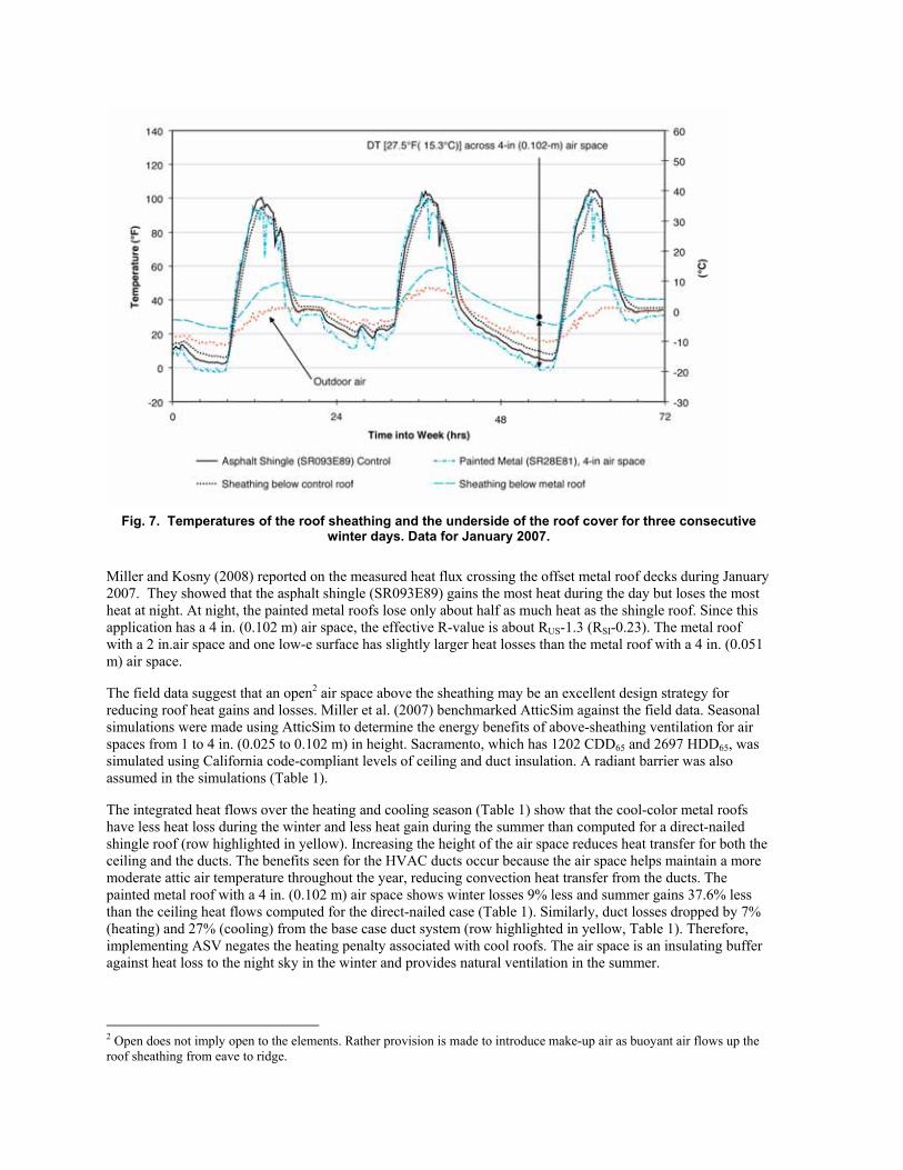
Fig. 7. Temperatures of the roof sheathing and the underside of the roof cover for three consecutive winter days. Data for January 2007.
Miller and Kosny (2008) reported on the measured heat flux crossing the offset metal roof decks during January 2007. They showed that the asphalt shingle (SR093E89) gains the most heat during the day but loses the most heat at night. At night, the painted metal roofs lose only about half as much heat as the shingle roof. Since this application has a 4 in. (0.102 m) air space, the effective R-value is about RUS-1.3 (RSI-0.23). The metal roof with a 2 in.air space and one low-e surface has slightly larger heat losses than the metal roof with a 4 in. (0.051 m) air space.
The field data suggest that an open2 air space above the sheathing may be an excellent design strategy for reducing roof heat gains and losses. Miller et al. (2007) benchmarked AtticSim against the field data. Seasonal simulations were made using AtticSim to determine the energy benefits of above-sheathing ventilation for air spaces from 1 to 4 in. (0.025 to 0.102 m) in height. Sacramento, which has 1202 CDD65 and 2697 HDD65, was simulated using California code-compliant levels of ceiling and duct insulation. A radiant barrier was also assumed in the simulations (Table 1).
The integrated heat flows over the heating and cooling season (Table 1) show that the cool-color metal roofs have less heat loss during the winter and less heat gain during the summer than computed for a direct-nailed shingle roof (row highlighted in yellow). Increasing the height of the air space reduces heat transfer for both the ceiling and the ducts. The benefits seen for the HVAC ducts occur because the air space helps maintain a more moderate attic air temperature throughout the year, reducing convection heat transfer from the ducts. The painted metal roof with a 4 in. (0.102 m) air space shows winter losses 9% less and summer gains 37.6% less than the ceiling heat flows computed for the direct-nailed case (Table 1). Similarly, duct losses dropped by 7% (heating) and 27% (cooling) from the base case duct system (row highlighted in yellow, Table 1). Therefore, implementing ASV negates the heating penalty associated with cool roofs. The air space is an insulating buffer against heat loss to the night sky in the winter and provides natural ventilation in the summer.
2 Open does not imply open to the elements. Rather provision is made to introduce make-up air as buoyant air flows up the roof sheathing from eave to ridge.

Table 1. Heating and cooling load for ceiling and air-conditioning ducts simulated in Sacramento, CA, for a roof and attic assembly with RUS-38 (RSI-6.7) ceiling insulation and RUS-6 (RSI-1) duct insulation. Duct
leakage is assumed to be 4% of the supply flow.
2.4 Airflow Measurements Using Tracer Gas Techniques
Measurements were made of the airflow underneath the stone-coated shake and S-mission tile roofs as the buoyancy-driven flow traveled from the soffit to the ridge of each roof. We designed a procedure using tracer gas techniques outlined in ASTM E 741 (ASTM 2000) and also by Lagus et al. (1988). The procedure required monitoring the decay rate of the tracer gas CO2 with time using the following equation, derived from a continuity balance for the concentration of CO2:
( )
⎥⎦
⎤⎢⎣
⎡−−
−=∞
∞
CCCtC
LNVi
tVOL
AirChannel& . (1)
Three CO2 monitors were placed inside each attic space, and sampling tubes were inserted into the inclined channel from the underside of the roof deck. The monitors sampled the gas concentration near the soffit, at the center of the roof, and within 2 ft (0.61 m) of the ridge vent. We injected the gas into the vent gap of the soffit and literally saturated the cavity with about 20,000 ppmv of CO2 gas. The polytropic throttling process occurring during the injection of CO2 from a pressurized cylinder (i.e., the gas throttles from about 2000 to 20 psi) required the gas to be artificially heated to about 110°F (43.3°C) before being injected into the vent cavity. After a substantial buildup of concentration registered on each monitor (20,000 ppmv of CO2), the gas injection was stopped, and the concentration was recorded at timed intervals. Data for the two stone-coated metal shake and the S-mission tile roofs were collected (Table 2); the calculated airflows ranged from about 10 to 20 cfm (0.0047 to 0.0094 m/s). The average velocity was about 0.3 feet/s (0.09 m/s).
Table 2. Airflow rate and bulk velocity measured under the stone-coated metal shake and S-mission roofs using tracer gas techniques
Light-gray shake on batten and counter-batten
Light-gray shake on batten and counter-batten (fascia vent)
S-mission tile on batten
Volume [VChannel in3(m3)]a 6673 (0.11) 6673 (0.11) 11,919 (0.195)
Airflow [cfm (m3/s)] 16.3 (0.0077) 17.7 (0.0084) 9.5 (0.0045)
Avg. velocity [Vair ft/s (m/s)] 0.26 (0.079) 0.28 (0.085) 0.27 (0.082) a Volume (VChannel) based on measured cross-sectional area of shake and distance from one CO2 metering station to another.
All measurements were made around solar noon when the roofs were at the highest temperatures and the highest heat flows were penetrating the attic. The light-gray shake with fascia vent does not appear to have increased airflow as compared with the shake with no fascia vent. The uncertainty of measurement for the tracer
gas technique was calculated on the basis of a first-order error analysis and is estimated at about ±25% of measurement. Therefore, the airflows are within the same range for the three roof systems.
2.5 Validation of ASV Algorithm
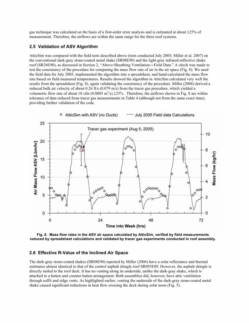
AtticSim was compared with the field tests described above (tests conducted July 2005; Miller et al. 2007) on the conventional dark-gray stone-coated metal shake (SR08E90) and the light-gray infrared-reflective shake roof (SR26E90), as discussed in Section 2, “Above-Sheathing Ventilation―Field Data.” A check was made to test the consistency of the procedure for computing the mass flow rate of air in the air space (Fig. 8). We used the field data for July 2005, implemented the algorithm into a spreadsheet, and hand-calculated the mass flow rate based on field measured temperatures. Results showed the algorithm in AtticSim calculated very well the results from the spreadsheet (Fig. 8), again validating the consistency of the procedure. Miller (2006) derived a reduced bulk air velocity of about 0.26 ft/s (0.079 m/s) from the tracer gas procedure, which yielded a volumetric flow rate of about 18 cfm (0.0085 m3/s) ±25% . Therefore, the airflows shown in Fig. 8 are within tolerance of data reduced from tracer gas measurements in Table 4 (although not from the same exact time), providing further validation of the code.
Fig. 8. Mass flow rates in the ASV air space calculated by AtticSim, verified by field measurements reduced by spreadsheet calculations and validated by tracer gas experiments conducted in roof assembly.
2.6 Effective R-Value of the Inclined Air Space
The dark-gray stone-coated shakes (SR08E90) reported by Miller (2006) have a solar reflectance and thermal emittance almost identical to that of the control asphalt shingle roof SR093E89. However, the asphalt shingle is directly nailed to the roof deck. It has no venting along its underside, unlike the dark-gray shake, which is attached to a batten and counter-batten arrangement. Both assemblies did, however, have attic ventilation through soffit and ridge vents. As highlighted earlier, venting the underside of the dark-gray stone-coated metal shake caused significant reductions in heat flow crossing the deck during solar noon (Fig. 5).
Miller (2006) reduced the deck heat flows for the week of August 2007 data (Fig. 5) by integrating the measured heat flux that crosses through the roof deck and the attic ceiling just over the daylight hours. The amount of heat removed by attic ventilation and by ASV was approximated by the following two energy balances:
HFTfloorAttic
HFTDeckRoof
ventAttic Q)(COS
QQ −
θ= (2)
)(COSQQQ
QHFT
DeckRoofMassabsSolarventDeck θ
−−= (3)
where
QSolar abs = ( ) ( ) ( )441 SkySAirODSSRSolar TTTTI −−−−− εσρ h ,
QMass =
tTCP ∂∂
ρΔ (thermal mass of roof cover and OSB decking included in QMass) ,
HFTceilingAtticQ = heat flux transducer (HFT) embedded in attic floor, and
HFTdeckRoofQ = heat flux transducer (HFT) embedded in roof deck.
The heat flow crossing the roof deck of the dark-gray shake is only 70% of the heat flow crossing the roof deck of the asphalt control shingle (Table 2). The 30% reduction in heat flow is due to deck venting despite the slight decrease in attic venting occurring under the dark-gray shake. However, ASV of the dark-gray shake is four times larger than is attic ventilation (Table 3). Thus, ASV for the dark-gray shake lowers the heat content of the attic and the interior surface temperatures, which in turn means lower amounts of heat penetrate the attic floor. As result, ASV dropped the heat flow through the attic floor by about 65% of the heat flow crossing the floor of the conventional attic assembly with the asphalt shingle roof.
Table 3. Roof deck and attic floor heat flows (Btu/ft2) integrated over the daylight hours for a week of July data (J/m2 = 1.1356E+04 * Btu/ft2)
Control shingle (SR093E89)
Light-Gray Shake Upt-CB (SR246E90)
Dark-Gray Shake Upt-CB (SR08E90)
Roof deck 1216.4 670.3 853.9
Attic floor 326.6 95.5 112.2
ventAtticQ 889.7 574.8 741.8
ventDeckQ 1280.6 2703.8
Note: Heat flows are corrected for projected attic floor area. Daylight is defined as the period when the solar flux normal to roof exceeds 30 Btu/hr·ft2 (94.5 W/m2).
The dark-gray and light-gray stone-coated metal shakes both have identical batten and counter-batten constructions and unpainted undersides. Both have soffit and ridge vents supporting attic ventilation. The solar reflectance of the light-gray shake is 0.25; reflectance for the darker gray shake is 0.08. The 0.17 increase in solar reflectance caused the heat flow crossing the roof deck of the light-gray shake to be less than the heat flow crossing the roof deck of the dark-gray stone-coated shake. The reduction is about 15% of the heat crossing the deck of the control shingle roof (Table 3). The 15% reduction is based on the daytime integration of deck heat flow; the 30% reduction due to ASV of the dark stone-coated shingle (previously discussed) can be added to the 15% reduction due to solar reflectance to yield a total 45% reduction in heat flow due to both ASV and
increased solar reflectance. The combined results (Fig. 3) observed using both cool-color pigments and ASV show that ventilating the deck is just as important as the boost in solar reflectance and may be the stronger player in reducing the heat gain to the attic assembly. It is interesting to note that the heat flow due to ASV of the hotter dark-gray shake is more than double the amount of heat flow swept away from the deck of the light-gray shake (Table 3). The hotter dark-gray shake incurs greater buoyant induced airflows, which implies there is a potential tradeoff between solar reflectance and ASV.
The above findings prompted Metal Construction Association (MCA) and its affiliates to continue further study. All metal roofs on ESRA were rearranged; two painted metal roofs were fastened directly to the deck. The one had RUS-1 (RSI-0.18) expanded polystyrene insulation (tradename FanFold) inserted between the metal pan and the sheathing. (R-value was measured in a Fox Model 605 Heat Flow Meter Apparatus.) The other metal roof was placed directly in contact with the deck. Other cool-color metal roofs were offset from the roof deck by 0.75, 1.5, and 4.0 in. (0.019, 0.038, and 0.038 m). The thermal resistances of the direct-to-deck assemblies are listed in Table 4 and acquired data were used to experimentally measure the thermal resistance of the inclined air space for the standing-seam metal roof, which in turn was used to benchmark computer predictions.
Table 4. Thermal resistances for direct-to-deck conventional shingle roof and painted metal roof.
Roof Assembly Asphalt shingle roof Standing-seam PVDF metal roof
Thickness [in (mm)]
RUS (RSI) Thickness [in (mm)]
RUS (RSI)
Roof 0.286 (7.3) 0.44 (0.077) 0.026 (0.66)
8.3E-5 (1.5E-5)
Sheathing 0.030 (0.76) 0.33 (0.058) 0.030
(0.76) 0.33 (0.058)
OSB Deck1 0.438 (11.1) 0.689 (0.121) 0.438
(11.1) 0.689 (0.121)
Total R-Value 1.458 (0.257) 1.018 (0.179) 1 Roof deck includes parallel conduction through 2 by 6 rafter located 16-in (0.41-m) on center.
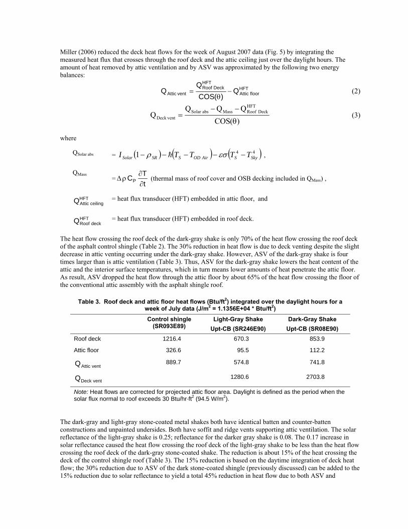
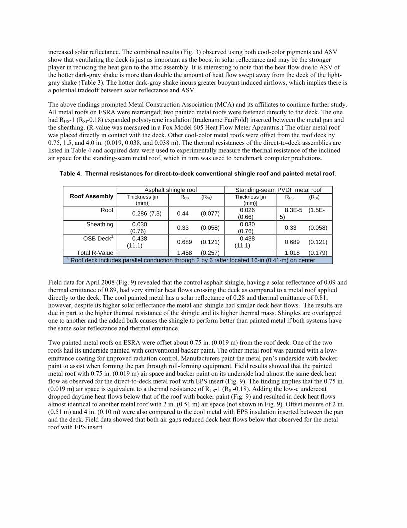
Field data for April 2008 (Fig. 9) revealed that the control asphalt shingle, having a solar reflectance of 0.09 and thermal emittance of 0.89, had very similar heat flows crossing the deck as compared to a metal roof applied directly to the deck. The cool painted metal has a solar reflectance of 0.28 and thermal emittance of 0.81; however, despite its higher solar reflectance the metal and shingle had similar deck heat flows. The results are due in part to the higher thermal resistance of the shingle and its higher thermal mass. Shingles are overlapped one to another and the added bulk causes the shingle to perform better than painted metal if both systems have the same solar reflectance and thermal emittance.
Two painted metal roofs on ESRA were offset about 0.75 in. (0.019 m) from the roof deck. One of the two roofs had its underside painted with conventional backer paint. The other metal roof was painted with a low-emittance coating for improved radiation control. Manufacturers paint the metal pan’s underside with backer paint to assist when forming the pan through roll-forming equipment. Field results showed that the painted metal roof with 0.75 in. (0.019 m) air space and backer paint on its underside had almost the same deck heat flow as observed for the direct-to-deck metal roof with EPS insert (Fig. 9). The finding implies that the 0.75 in. (0.019 m) air space is equivalent to a thermal resistance of RUS-1 (RSI-0.18). Adding the low-e undercoat dropped daytime heat flows below that of the roof with backer paint (Fig. 9) and resulted in deck heat flows almost identical to another metal roof with 2 in. (0.51 m) air space (not shown in Fig. 9). Offset mounts of 2 in. (0.51 m) and 4 in. (0.10 m) were also compared to the cool metal with EPS insulation inserted between the pan and the deck. Field data showed that both air gaps reduced deck heat flows below that observed for the metal roof with EPS insert.
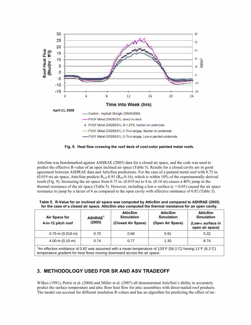
Fig. 9. Heat flow crossing the roof deck of cool-color painted metal roofs.
AtticSim was benchmarked against ASHRAE (2005) data for a closed air space, and the code was used to predict the effective R-value of an open inclined air space (Table 5). Results for a closed cavity are in good agreement between ASHRAE data and AtticSim predictions. For the case of a painted metal roof with 0.75 in. (0.019 m) air space, AtticSim predicts RUS-0.91 (RSI-0.16), which is within 10% of the experimentally derived result (Fig. 9). Increasing the air space from 0.75 in. (0.019 m) to 4 in. (0.10 m) causes a 40% jump in the thermal resistance of the air space (Table 5). However, including a low-e surface (ε = 0.05) caused the air space resistance to jump by a factor of 6 as compared to the open cavity with effective emittance of 0.82 (Table 5).
Table 5. R-Value for an inclined air space was computed by AtticSim and compared to ASHRAE (2005) for the case of a closed air space. AtticSim also computed the thermal resistance for an open cavity.
Air Space for 4-in-12 pitch roof
ASHRAE1 (2005)
AtticSim Simulation
(Closed Air Space)
AtticSim Simulation
(Open Air Space)
AtticSim Simulation
(Low-ε surface in open air space)
0.75-in (0.019-m) 0.70 0.68 0.91 5.32
4.00-in (0.10-m) 0.74 0.77 1.30 8.74 1An effective emittance of 0.82 was assumed with a mean temperature of 133°F (56.1°C) having 11°F (6.1°C) temperature gradient for heat flows moving downward across the air space.
3. METHODOLOGY USED FOR SR AND ASV TRADEOFF
Wilkes (1991), Petrie et al. (2004) and Miller et al. (2007) all demonstrated AtticSim’s ability to accurately predict the surface temperature and attic floor heat flow for attic assemblies with direct-nailed roof products. The model can account for different insulation R-values and has an algorithm for predicting the effect of air-

conditioning ducts placed in the attic, as reported by Petrie et al. (1998) and described in ASTM C 1340 (2004). Salient features of AtticSim (including the source code) are provided by Wilkes (1991). Miller et al. (2007) modified the code for inclusion of above-sheathing ventilation. He reported on AtticSim’s predictions being within ±5% of field measurements for surface temperatures and documented that integrated ceiling and deck heat fluxes were predicted within ±10% of field measurements when exercised for the case of ASV.
3.1 AtticSim Computer Tool
ASTM Standard C 1340-04 (2004) and Energy Plus were used to compute the heat transfer through ceilings under attics. Simulations were made for the ASHRAE climate zones and for Sacramento, CA (Table 4). An attic of 1539 sq ft (143 m2) with a roof pitch of 18° was modeled with cool-color stone-coated metal, standing-seam metal, and asphalt shingle; solar reflectance of the cool roofs was set at 0.25 and at 0.40. Simulations assumed supply and return air-conditioning ducts (cylindrical metal) installed in the attic. The supply duct surface area was set at 304 ft2 (28.7 m2). The surface area of the return duct exposed in the unconditioned attic was assumed to be 176 ft2 (16.4 m2) . Energy Plus estimated the hourly indoor air temperature and hourly run times for a SEER 13 air conditioner as it cooled the home, and for Heating by an 85% efficient gas furnace. The Home Energy Rating System (HERS) Building Energy Simulation Test (BESTEST) served as the simulated home (NREL 1995). It is used as a standard for evaluating the credibility of softwares used by HERS to predict energy use in homes.
Energy Plus computed hourly values of the mass flow rate of air in the duct system and the bulk air temperature entering the ducts for all climates listed in Table 6. Hourly values of duct flow rate, bulk air temperature, the percentage “on” time of the HVAC, and the indoor air temperature were written to auxiliary files and read by AtticSim for computing the roof and attic load as coupled to the home simulated in the various ASHRAE climate zones. Low-slope simulations assumed that the HVAC was in the conditioned space. Table 6. The ASHRAE climate zones and CA climate zone 12 were used to investigate the tradeoff of ASV
with solar reflectance for low- and steep-slope roofs.
The roof heat transfer for offset-mounted metal roofs was computed for the cooling and heating season and compared with data for a painted cool-color metal roof with a prescriptive requirement of 0.25 solar reflectance3. The base case roof was fastened directly to the roof deck.
The ceiling insulation was set to comply with ASHRAE Standard 90.1 for low-slope commercial roofing (ASHRAE 2007a) and with ASHRAE Standard 90.2 for steep-slope commercial and residential homes (ASHRAE 2007b). For retrofit practice, the ceiling and duct insulation were assumed to comply with thermal resistance levels published in ASHRAE 90 (1980), Table 6. Air leakage of the ductwork is unknown; however,
3 The California Energy Commission’s Title 24 building standards has set the minimal prescriptive solar reflectance at 0.20; however, painted metal and asphalt shingles can exploit cool color pigments and reach solar reflectance values of about 0.25.

for demonstration purposes, simulations assumed air losses of 10% of supply airflow for existing homes built to ASHRAE 90 (1980) code and 4% leakage for inspected, well-installed ductwork (Cummings, Toole, and Moyer 1990, CEC 2008).
3.2 Tasks Required to Judge the SR Tradeoff with ASV
The MCA developed specific tasks for judging the tradeoff between solar reflectance and above-sheathing ventilation for both low- and steep-slope roof assemblies. The tasks, outlined below, required the computation of the ceiling heat transfer over the cooling season for direct-to-deck cool roofs and for offset-mounted roofs with and without cool colors. The tool AtticSim/Energy Plus compared the data and generated guidelines for the tradeoffs between SR and ASV across the varied climates listed in Table 6.
The physics for the transfer of heat across the inclined air space of offset-mounted stone-coated and standing-seam metal roofs is similar to the heat transfer across the inclined air channel formed by roof-mounted solar collectors. Comprehensive reviews of both experimental and theoretical results are available in the literature. Hollands et al. (1976), Arnold, Catton, and Edwards (1976), Azevedo (1984), and, most recently, Brinkworth (2000) studied this situation as applied to flat-plate photovoltaic cladding. Miller (2007) used these foundational works to help formulate and then validate an algorithm for ASV. He benchmarked an ASTM protocol C-1340 (ASTM 2004) against data for both the stone-coated metal and standing-seam metal roofs. The key to the algorithm is an a priori knowledge of the airflow within the air space for computing the convection heat transfer penetrating into the roof deck. Given the airflow, energy balances can be derived for the external and internal surfaces of the roof and attic and solved using open literature correlations for predicting the temperature and heat flow. Miller (2007) reported on AtticSim’s predictions being within ±5% of field measurements for surface temperatures and integrated ceiling and deck heat fluxes being within ±10% of field measurements when exercised for the case of ASV.
This work presents an alternative approach for developing ways to meet prescriptive requirements for steep-slope residential and non-residential roofing. Equal heat fluxes are required through the ceilings of roofs having different combinations of surface radiation properties and/or building configurations. Tasks 1 through 3 are listed below, and the results detailed in the following sections show how roofs fitted with an inclined air space above the roof deck can meet cool roof requirements regulated by the 2008 Title 24 code and the EPA Energy Star programs in all eight ASHRAE climate zones and Sacramento, CA.
AtticSim/EnergyPlus computed the heat flux crossing the conditioned space below a roof and attic assembly having a minimal code level of ceiling insulation and with no radiant barrier. Results were computed for a roof with SR-0.25 asphalt shingles (0.15 weathered) fastened directly to the roof deck, and for the same shingle roof but with ASV, for all climate zones listed in Table 6. All computations assume weathered reflectance values to be consistent with the 2008 Title 24 guidelines. AtticSim/EnergyPlus used these computations to determine the equivalent SR for a direct-to-deck shingle roof that equals the heat flux for the case of a metal SR-0.25 (0.15 weathered) roof with ASV. • Task 1A: Determine SR needed for steep-slope (18.4°) roof with ASV (minimum ¾ in. of continuous air
gap) to match load of an SR-0.25 (0.15 weathered) cool roof fastened directly to deck.
• Task 1B: Determine the SR needed in a steep-slope roof with ASV (minimum ¾ in. of continuous air gap) to match load of an SR-0.40 roof (0.25 weathered) fastened directly to deck. (Pending California legislation will potentially raise standards to require SR-0.40 residential roofs.)
• Task 1C: Determine the SR needed in a low-slope (9.5°) roof with ASV to match load of an SR-0.65 (0.50 weathered) cool roof fastened directly to deck. • Task 2: Determine SR needed for a steep-slope (18.4°) direct-to-deck roof to match load of a cool roof with ASV.
• Task 3: Determine SR needed for a low-slope (9.5°) direct-to-deck roof to match load of an SR-0.65 (0.50 weathered) cool roof with ASV. AtticSim/Energy Plus computed the heat flux for a dark, heat-absorbing roof (SR 0.05) and the heat flux of an aged cool roof (0.65 SR, 0.50 SR weathered) with ASV, for all climate zones listed in Table 6. Data was then reduced and the needed SR values documented.
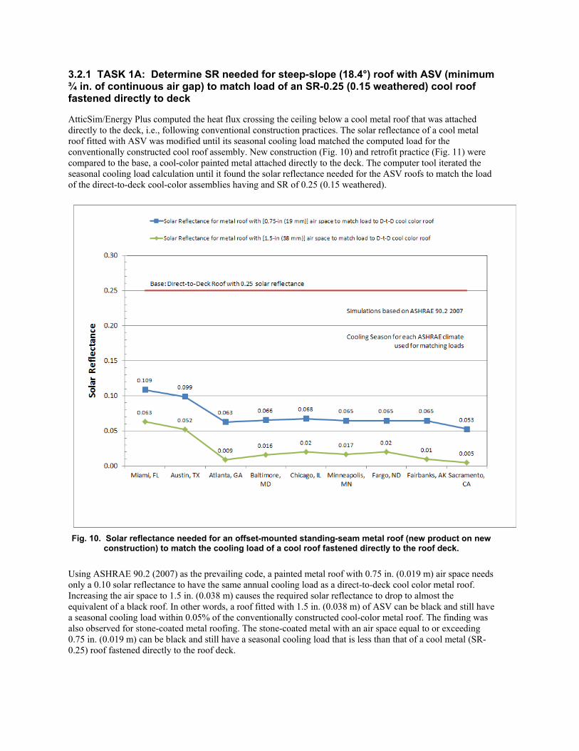
3.2.1 TASK 1A: Determine SR needed for steep-slope (18.4°) roof with ASV (minimum ¾ in. of continuous air gap) to match load of an SR-0.25 (0.15 weathered) cool roof fastened directly to deck
AtticSim/Energy Plus computed the heat flux crossing the ceiling below a cool metal roof that was attached directly to the deck, i.e., following conventional construction practices. The solar reflectance of a cool metal roof fitted with ASV was modified until its seasonal cooling load matched the computed load for the conventionally constructed cool roof assembly. New construction (Fig. 10) and retrofit practice (Fig. 11) were compared to the base, a cool-color painted metal attached directly to the deck. The computer tool iterated the seasonal cooling load calculation until it found the solar reflectance needed for the ASV roofs to match the load of the direct-to-deck cool-color assemblies having and SR of 0.25 (0.15 weathered).
Fig. 10. Solar reflectance needed for an offset-mounted standing-seam metal roof (new product on new construction) to match the cooling load of a cool roof fastened directly to the roof deck.
Using ASHRAE 90.2 (2007) as the prevailing code, a painted metal roof with 0.75 in. (0.019 m) air space needs only a 0.10 solar reflectance to have the same annual cooling load as a direct-to-deck cool color metal roof. Increasing the air space to 1.5 in. (0.038 m) causes the required solar reflectance to drop to almost the equivalent of a black roof. In other words, a roof fitted with 1.5 in. (0.038 m) of ASV can be black and still have a seasonal cooling load within 0.05% of the conventionally constructed cool-color metal roof. The finding was also observed for stone-coated metal roofing. The stone-coated metal with an air space equal to or exceeding 0.75 in. (0.019 m) can be black and still have a seasonal cooling load that is less than that of a cool metal (SR-0.25) roof fastened directly to the roof deck.

Computations based on existing construction using ASHRAE 90 (1980) are very eye opening (Fig. 11). For retrofit work, the offset-mounted metal roof could be perfectly black and still have the same annual cooling load as the cool metal direct-to-deck base case! The data document that the MCA is in strong position to petition local and state agencies for inclusion of their offset-mounted standing-seam and stone-coated metal products as cool roof systems.
Fig. 11. Solar reflectance needed for an offset-mounted standing-seam metal roof (new product on existing construction) to match the cooling load of a cool roof fastened directly to the roof deck.
Three simulations per climate zone were needed to develop the solar reflectance labels in Fig. 11. These SR values yield a seasonal cooling load for an ASV roof that equals the load of a cool roof fastened directly to the deck with ASHRAE 90.1 (1980) levels of insulation. The first simulation was conducted for a given climate zone ( as an example, Atlanta, GA, which represents ASHRAE climate zone 3). Cumulative cooling and heating loads were written to an external file. A second run was made for an SR-0.25 roof fitted with ASV; its cooling and heating loads were also written to the external file. The third run read the data from the external file and used an interpolating scheme to adjust the solar reflectance of the roof with ASV until its annual cooling load matched the annual cooling load of the cool metal roof fastened directly to the deck. These are the solar reflectance labels shown in Fig. 11.
Three contiguous July days are shown in Fig. 12 for the base cool metal roof having solar reflectance of 0.25. Its peak-day heat flow crossing the attic floor is about 40% higher than the load for a cool roof fitted with ASV. By modifying the solar reflectance of the roof with ASV (see the “+” symbols in Fig. 12), its seasonal load is made about equal to the load for the direct-to-deck base roof. (See line defined by + symbols in Fig. 12.) For several simulations, iterations yielded a negative solar reflectance to match loads, which is unrealistic because

the lowest achievable solar reflectance is zero. Therefore, the negative values imply that the ASV roof can be black and still perform better than a direct-to-deck cool metal roof having 0.25 solar reflectance.
Fig.12. Simulations show (on the line defined by the + symbols) the match of ceiling load between a direct-to-deck cool metal roof and a roof fitted with ASV. The loads were matched by adjusting the solar reflectance
of the ASV roof (to zero or negative solar reflectance).
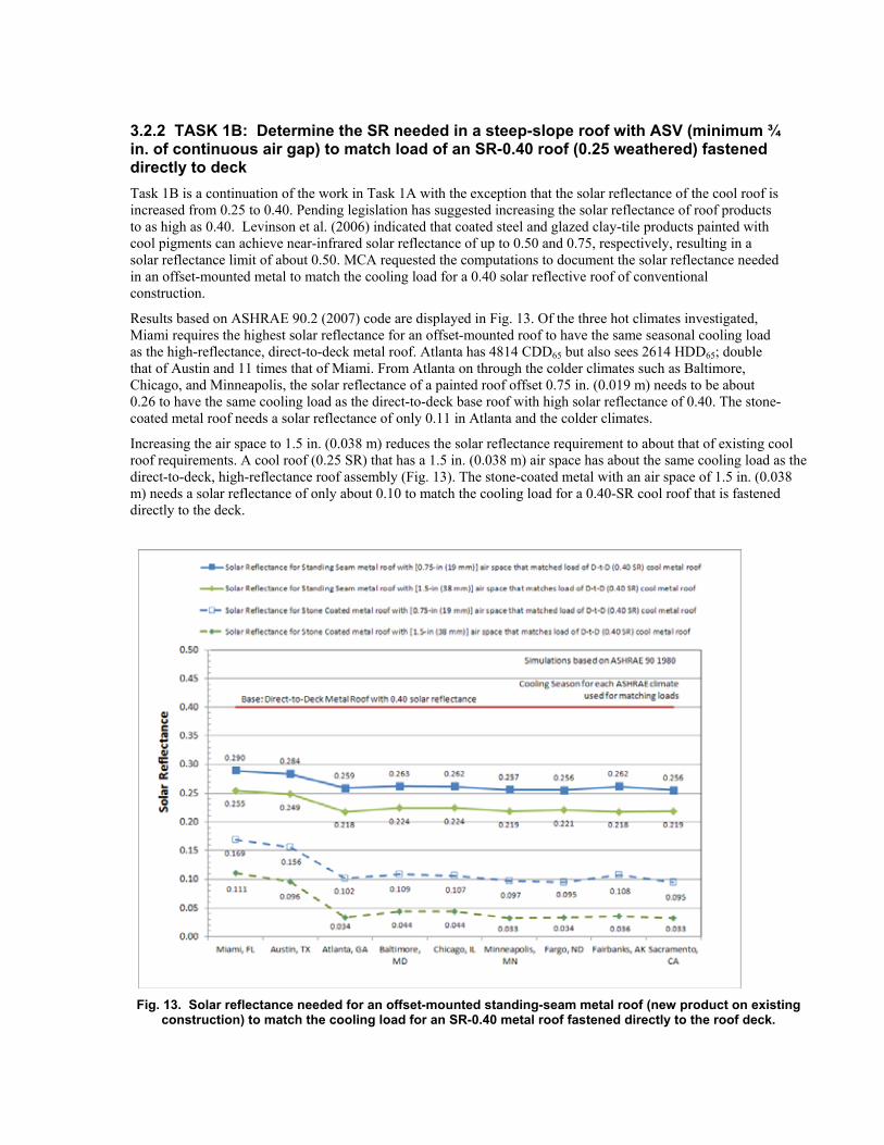
3.2.2 TASK 1B: Determine the SR needed in a steep-slope roof with ASV (minimum ¾ in. of continuous air gap) to match load of an SR-0.40 roof (0.25 weathered) fastened directly to deck Task 1B is a continuation of the work in Task 1A with the exception that the solar reflectance of the cool roof is increased from 0.25 to 0.40. Pending legislation has suggested increasing the solar reflectance of roof products to as high as 0.40. Levinson et al. (2006) indicated that coated steel and glazed clay-tile products painted with cool pigments can achieve near-infrared solar reflectance of up to 0.50 and 0.75, respectively, resulting in a solar reflectance limit of about 0.50. MCA requested the computations to document the solar reflectance needed in an offset-mounted metal to match the cooling load for a 0.40 solar reflective roof of conventional construction.
Results based on ASHRAE 90.2 (2007) code are displayed in Fig. 13. Of the three hot climates investigated, Miami requires the highest solar reflectance for an offset-mounted roof to have the same seasonal cooling load as the high-reflectance, direct-to-deck metal roof. Atlanta has 4814 CDD65 but also sees 2614 HDD65; double that of Austin and 11 times that of Miami. From Atlanta on through the colder climates such as Baltimore, Chicago, and Minneapolis, the solar reflectance of a painted roof offset 0.75 in. (0.019 m) needs to be about 0.26 to have the same cooling load as the direct-to-deck base roof with high solar reflectance of 0.40. The stone-coated metal roof needs a solar reflectance of only 0.11 in Atlanta and the colder climates.
Increasing the air space to 1.5 in. (0.038 m) reduces the solar reflectance requirement to about that of existing cool roof requirements. A cool roof (0.25 SR) that has a 1.5 in. (0.038 m) air space has about the same cooling load as the direct-to-deck, high-reflectance roof assembly (Fig. 13). The stone-coated metal with an air space of 1.5 in. (0.038 m) needs a solar reflectance of only about 0.10 to match the cooling load for a 0.40-SR cool roof that is fastened directly to the deck.
Fig. 13. Solar reflectance needed for an offset-mounted standing-seam metal roof (new product on existing construction) to match the cooling load for an SR-0.40 metal roof fastened directly to the roof deck.

3.2.3 TASK 1C: Determine the SR needed in a low-slope (9.5°) roof with ASV to match load of an SR-0.65 (0.50 weathered) cool roof fastened directly to deck
AtticSim/EnergyPlus computed the heat flux for a low-slope, SR-0.65 (0.50 weathered) roof and compared it to the load for a roof fitted with a 2 in. (0.051 m) air space for all climate zones listed in Table 6. The code determined the heat flux for the low-slope roof with 0.65 SR (0.50 weathered) and matched its seasonal cooling load to the offset-mounted assembly by altering the solar reflectance of the offset-mounted system. Results for ASHRAE 90.1 (2007) and ASHRAE 90 (1980) are listed respectively in tables 7 and 8.
Table 7. Solar reflectance needed for a painted metal roof fitted with ASV to match the cooling load of an SR-0.65 (SR-0.55 aged) cool white roof mounted directly to roof deck. [ASHRAE 90.1 (2007) code]
For new product fastened directly to the roof deck and having a roof solar reflectance of 0.65, the offset-mounted roof must have a solar reflectance greater than 0.55 for all climates zones (Table 7). For aged product the increase in solar reflectance needed to match loads is less than the prescriptive code of 0.55. As an example, in Miami a 0.40 solar reflectance is needed for a roof with 2 in. (0.051 m) air space to match the load of an SR-0.55 (aged) roof that is fastened directly to the roof deck. In Chicago, an SR-0.35 roof with 2 in. (0.051 m) air space has the same cooling load as the 0.55 direct-to-deck assembly.
Table 8. Solar reflectance needed for a painted metal roof with ASV to match the cooling load of an SR-0.65 (SR-0.55 aged) cool white roof mounted directly to the roof deck. [ASHRAE 90 (1980) code]
Generally the results for existing construction based on the ASHRAE 90 (1980) code are very similar to those computed for the new 2007 code (Table 7 compared to Table 8). However, the annual loads are very different between the two cases because, for example, Chicago calls for RUS-20 (RSI-3.5) ceiling insulation in 2007 while in 1980 ASHRAE specified RUS-13.3 (RSI-2.3).
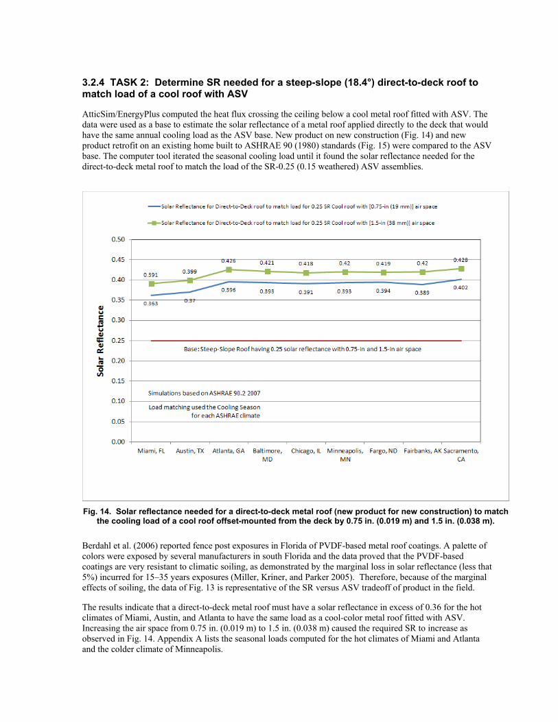
3.2.4 TASK 2: Determine SR needed for a steep-slope (18.4°) direct-to-deck roof to match load of a cool roof with ASV
AtticSim/EnergyPlus computed the heat flux crossing the ceiling below a cool metal roof fitted with ASV. The data were used as a base to estimate the solar reflectance of a metal roof applied directly to the deck that would have the same annual cooling load as the ASV base. New product on new construction (Fig. 14) and new product retrofit on an existing home built to ASHRAE 90 (1980) standards (Fig. 15) were compared to the ASV base. The computer tool iterated the seasonal cooling load until it found the solar reflectance needed for the direct-to-deck metal roof to match the load of the SR-0.25 (0.15 weathered) ASV assemblies.
Fig. 14. Solar reflectance needed for a direct-to-deck metal roof (new product for new construction) to match the cooling load of a cool roof offset-mounted from the deck by 0.75 in. (0.019 m) and 1.5 in. (0.038 m).
Berdahl et al. (2006) reported fence post exposures in Florida of PVDF-based metal roof coatings. A palette of colors were exposed by several manufacturers in south Florida and the data proved that the PVDF-based coatings are very resistant to climatic soiling, as demonstrated by the marginal loss in solar reflectance (less that 5%) incurred for 15–35 years exposures (Miller, Kriner, and Parker 2005). Therefore, because of the marginal effects of soiling, the data of Fig. 13 is representative of the SR versus ASV tradeoff of product in the field.
The results indicate that a direct-to-deck metal roof must have a solar reflectance in excess of 0.36 for the hot climates of Miami, Austin, and Atlanta to have the same load as a cool-color metal roof fitted with ASV. Increasing the air space from 0.75 in. (0.019 m) to 1.5 in. (0.038 m) caused the required SR to increase as observed in Fig. 14. Appendix A lists the seasonal loads computed for the hot climates of Miami and Atlanta and the colder climate of Minneapolis.

Results were generated for new product applied to existing homes built to ASHRAE 90 (1980) standards (Fig. 15). Because the thermal insulation levels are less for 1980, the comparisons (Fig. 14 versus Fig. 15) are based on significantly different loads. Yet results are about the same, showing as expected that solar reflectance is directly proportional to the building load. Therefore, whether for new or retrofit construction, the tradeoff between solar reflectance and ASV is similar as building codes upgrade ceiling insulation levels.
Fig. 15. Solar reflectance needed for a direct-to-deck metal roof (new product retrofit on existing home) to match the cooling load of a cool roof offset-mounted from the deck by 0.75 in. (0.019 m) and 1.5 in. (0.038 m).
Tradeoffs were also made for aged products assuming the 2008 Title 24 definition for aged product as reported by Levinson et al. (2005), who estimated the aged product using the following: ( )ooductPrNewoaged 7.0 ρ−ρ+ρ=ρ (4)
where the constant ρo = 0.20. Miller, Kriner and Parker (2005) reported data for PVDF metals which shows the 3-year loss in reflectance predicted by Eq. 4 as severe because the PVDF-based coatings demonstrated losses in solar reflectance of less that 5% after 15–35 years exposures. More recently, Levinson (2011) proposed an update for provisional aged solar reflectance using the formulation:
( )ooductPrNewoaged ρ−ρβ+ρ=ρ (5)
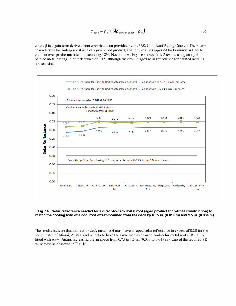
where β is a gain term derived from empirical data provided by the U.S. Cool Roof Rating Council. The β term characterizes the soiling resistance of a given roof product, and for metal is suggested by Levinson as 0.85 to yield an over-prediction rate not exceeding 18%. Nevertheless Fig. 16 shows Task 2 results using an aged painted metal having solar reflectance of 0.15, although the drop in aged solar reflectance for painted metal is not realistic.
Fig. 16. Solar reflectance needed for a direct-to-deck metal roof (aged product for retrofit construction) to match the cooling load of a cool roof offset-mounted from the deck by 0.75 in. (0.019 m) and 1.5 in. (0.038 m).
The results indicate that a direct-to-deck metal roof must have an aged solar reflectance in excess of 0.28 for the hot climates of Miami, Austin, and Atlanta to have the same load as an aged cool-color metal roof (SR = 0.15) fitted with ASV. Again, increasing the air space from 0.75 to 1.5 in. (0.038 to 0.019 m) caused the required SR to increase as observed in Fig. 16.

3.2.5 TASK 3: Determine SR needed for a low-slope (9.5°) direct-to-deck roof to match load of an SR-0.65 (0.50 weathered) cool roof with ASV
AtticSim/Energy Plus computed the heat flux for a dark, heat-absorbing roof (SR 0.05) as compared to a fresh and aged cool roof (0.65 SR new and 0.50 aged) for all climate zones listed in Table 6. The code determined the heat flux for the case having 0.65 SR (0.50 weathered) with ASV and matched the seasonal cooling load for a direct-to-deck metal by increasing its solar reflectance from 0.05 until its cooling load was within 0.05% of the ASV case. Results for ASHRAE 90.1 (2007) and ASHRAE 90 (1980) are listed respectively in tables 9 and 10.
Table 9. Solar reflectance needed for a direct-to-deck metal roof [ASHRAE 90.1 (2007) code] to match the
cooling load of a cool white roof offset-mounted by 2.0 in. (0.051 m).
For new product fitted with ASV and having a roof solar reflectance of 0.65, the direct-to-deck roof must have a solar reflectance greater than 0.71 for all climates zones. The increase in solar reflectance is not as large as that observed for steep-slope roofs in Task 2 but is expected because low-slope roofs require an initally higher solar reflectance of 0.65, as compared to 0.25 required for steep-slope roofs. For aged product the increase in solar reflectance needed to match loads is only 6% higher than the aged base case. As an example, in Miami a direct-to-deck metal roof must have solar reflectance of 0.585 to match the cooling load for a low-slope white metal roof fitted with a 2 in. (0.051 m) air space. Appendix B lists the seasonal loads computed for the hot climates of Miami and Atlanta and the colder climate of Minneapolis.
Table 10. Solar reflectance needed for a direct-to-deck metal roof [ASHRAE 90 (1980) code] to match the
cooling load of a cool white roof offset-mounted from the deck by 2.0 in. (0.051 m).
Generally the results for existing construction based on the ASHRAE 90 (1980) code are very similar to those computed for the new 2007 code (Table 10 compared to Table 9). However, the annual loads are very different between the two cases because, for example, Chicago calls for RUS-20 (RSI-3.5) ceiling insulation in 2007 while in 1980 ASHRAE specified RUS-13.3 (RSI-2.3).
4. CONCLUSIONS
Field tests were conducted to examine the effects of cool-color pigments on standing-seam metal roofs and stone-coated metal roofs that were attached directly to the roof deck or offset-mounted off the roof deck. The metal roofing manufacturers and pigment (colorant) manufacturers selected appropriate cool-color pigments; applied them to stone-coated metal shakes, S mission tile, and painted metal roof products; and field-tested the prototypes on a steep-slope roof assembly located at the ORNL Buildings Technology Research Integration Center (BTRIC). Our test data show that the combination of improved solar reflectance afforded by cool-color pigments and above-sheathing ventilation make offset-mounted metal roofs energy efficient. These materials can offer excellent energy credits as steep-slope cool roof products. The light-gray stone-coated metal shakes offset-mounted with a batten and counter-batten system reduced the heat transfer penetrating the roof deck by about 45% compared to the heat penetrating the deck of an attic covered with an asphalt shingle roof. About 15% of the reduction was due to cool-color pigments, while 30% of the reduction was due to ASV.
During the winter exposure the inclined air space helped reduce the heat loss from the roof. Stone-coated metal and standing-seam metal roofs elevated off the roof deck had wintertime heat losses from the ceiling that were less than the losses measured for the direct-deck asphalt shingle roof. AtticSim/EnergyPlus simulations showed the painted metal roof with a 4 in (0.102 m) air space had winter losses 9% less and summer gains 37.6% less than the ceiling heat flows computed for the direct-nailed shingle. Similarly, duct losses dropped by 7% (heating) and 27% (cooling). Therefore, implementing above-sheathing ventilation negates the heating penalty associated with cool roofs. The air space is an insulating buffer against heat loss to the night sky in the winter and provides natural ventilation in the summer. Therefore, offset-mounting metal roofs provides the metal roof industry the opportunity to market their roof products in the more predominant heating load climates.
Field data also indicated that the measured summertime deck heat flows for an asphalt shingle roof having solar reflectance of 0.09 and thermal emitance of 0.89 was about the same as that measured for a cool-color standing-seam metal roof having a higher solar reflectance of 0.28 and thermal emittance of 0.85. Both roof asemblies were attached directly to the deck. Therefore AtticSim/ EnergyPlus simulations based on equal cool roof reflectances for the two systems revealed that the asphalt shingle yielded better performance if both roofs were direct-to-deck applications. As result, simulations were conducted using a painted metal fixed directly to the roof deck as the base to show the tradeoff between solar reflectance and above-sheathing ventilation.
AtticSim/EnergyPlus was used to judge the tradeoffs between solar reflectance and above-sheathing ventilation for both low- and steep-slope roof assemblies. The computer tool iterated on the solar reflectance of a given metal roof until it equaled the annual load for a base cool roof system. Results of the work are described below.
• Task 1A: Solar Reflectance needed for a steep-slope roof fitted with ASV to match the load of a SR 0.25 cool roof attached directly to the deck.
A painted metal roof with 0.75 in. (0.019 m) air space needs only a 0.10 solar reflectance to have the same annual cooling load as a direct-to-deck cool-color metal roof. A standing-seam metal roof fitted with 1.5 in. (0.038 m) of ASV or a stone coated metal fitted with 0.75 in. (0.019 m) air space can both be black and still have a seasonal cooling load within 0.05% of the conventionally constructed cool-color (solar reflectance of 0.25) metal roof. Computations for retrofit application based on ASHRAE 90 (1980) shows ASV air spaces of 0.75 and 1.5 in. (0.019 and 0.038 m) would permit black roofs to have cooling loads equivalent to the direct to deck cool roof.
• Task 1B: Solar Reflectance needed for a steep-slope roof fitted with ASV to match the load of a cool roof (solar reflectance of 0.40) attached directly to the deck.
The hot climates of Miami, Austin and Atlanta require respectively solar reflectance of 0.30, 0.29 and 0.26 for an offset-mounted standing roof [0.75 in. (0.019 m)] to have the same seasonal cooling load as the 0.40 solar reflective direct to deck metal roof. For climates colder than Atlanta, having 4814 CDD65 and 2614 HDD65, the required solar reflectance for the ASV assemblies remain relatively level. Therefore a cool-color roof (solar

reflectance of 0.25) that is fitted with at least 0.75 in. (0.019 m) of ASV performs as well as a 0.40 reflective roof that is attached directly to the roof deck. The stone-coated metal with an air space of 1.5 in. (0.038 m) need only have a solar reflectance of about 0.10 to match the cooling load for a 0.40 solar reflective cool roof that is fastened directly to the deck.
• Task 1C: Solar Reflectance needed for a low-slope roof fitted with ASV to match the load of a cool roof (solar reflectance 0.65) attached directly to the deck.
A painted metal roof with 2.0 in. (0.051 m) air space must have a solar reflectance slightly above 0.55 for all climate zones to match 0.65 direct to deck. For aged product the increase in solar reflectance needed to match load is less than the prescriptive code of 0.55. The results for existing construction based on the ASHRAE 90 (1980) code are very similar to those computed for the current 2007 code.
• Task 2: Solar Reflectance needed for a direct to deck steep-slope roof to match the load of a cool roof fitted with ASV.
The results indicate that a direct-to-deck metal roof must have a solar reflectance in excess of 0.36 for the hot climates of Miami, Austin and Atlanta to have the same load as a cool-color metal roof (fresh product with SR of 0.25) fitted with ASV. Increasing the air space from 0.75 in. (0.019 m) to 1.5 in. (0.038 m) caused the required SR for the direct-to-deck metal roof to increase to about 0.39. Retrofit application using ASHRAE 90 (1980) standards yielded similar tradeoffs between solar reflectance and ASV. The results for fresh solar reflectances are more realistic than those for aged product because the 2008 Title 24 aged reflectance is too severe for stone-coated and PVDF metals.These metals have soiling losses of about 10% for fresh product while 2008 Title 24 assumes a 40% drop due to climatic soiling.
• Task 3: Solar Reflectance needed for a direct-to-deck, low-slope roof to match the load of a cool roof fitted with 2 in. (0.051 m) of ASV.
For new product fitted with ASV and having a roof solar reflectance of 0.65, the direct-to-deck roof must have a solar reflectance greater than 0.71 for all climates zones for equal loads. For aged product the increase in solar reflectance needed to match loads is about 6% higher than the aged base case having solar reflectance of 0.55. The results for existing construction based on the ASHRAE 90 (1980) code are very similar to those computed for the new 2007 code.

5. RECOMMENDATIONS
The contents of this report provide the MCA with credible and compelling evidence of the benefits provided by roof assemblies fitted with above-sheathing ventilation in each of the ASHRAE climate zones. Results should be peer reviewed by MCA and its affiliates and the data used to convince local, state. and national code officials to adopt prescriptive requirements for above-sheathing ventilation. Specifically, the inclusion of an air space ≥ 1.0 in. (0.0254 m) in stone-coated and standing-seam metal roofs should be classified as a cool roof because their annal cooling loads are less than that for a 2008 Title 24 or for the EPA’s Energy Star cool roof.
The field data confirms that an open air space above the sheathing is an excellent design strategy for reducing roof heat gains and losses. It improves the durability of the roof assembly because the natural convection ventilation drys the deck of moisture. It also affords the roof protection from wildfires common in wildlife-urban environment interfaces. The thermally induced bouyant flow increases as the metal’s temperature increases. Therefore intense heat is not directly conducted through the metal into the roof deck and ignition is delayed if not eliminated from the system. The MCA should conduct fire testing with stone-coated metal roofs and standing-seam metal roofs applied direct to deck and offset from the roof deck at different air spacings to assess the effect of the air space on retarding the ignition of the roof deck.
In southern California, homeowner associations are selecting new roof products and replacing all existing roofs in an individual association with the same product. The major incentive for the California homeowner is reduced home insurance rates for fire protection. However, moderate savings are also realized from installing new roofs that integrate cool roofs, above-sheathing ventilation with a low-e surface in the air space, insulation, and thermal mass.
What utilities and building owners need is annual performance metrics prioritizing retrofit choices. Further collaborative study and assessment by utilities and research institutions is needed to develop a portfolio of the best available materials and construction methods that, through rebate incentives, reduce the building owners’ costs sufficiently and justify for the homeowner the economics of higher up-front material and installation costs.
38
6. REFERENCES Akbari, H., Levinson, R. 2008. “Evolution of Cool-Roof Standards in the U.S.,” Advances in Building Energy
Research, Vol. 2, p 1-32.
Akbari, H., P. Berdahl, R. Levinson, R. Wiel, A. Desjarlais, W. Miller, N. Jenkins, A. Rosenfeld, and C. Scruton. 2004. “Cool Colored Materials for Roofs,” ACEEE Summer Study on Energy Efficiency in Buildings, Proceedings of American Council for an Energy Efficient Economy, Pacific Grove, CA, August.
Arnold, J. N., I. Catton, and D. K. Edwards. 1976. “Experimental Investigation of Natural Convection in Inclined Rectangular Regions of Differing Aspect Ratios,” Journal of Heat Transfer, February, 67–71.
American Society for Testing and Materials(ASTM). 2004. Standard Practice for Estimation of Heat Gain or Loss through Ceilings under Attics Containing Radiant Barriers by Use of a Computer Program. Standard C 1340-04. West Conshohocken, Penn.: American Society for Testing and Materials.
ASTM. 2000. ASTM Standard E741-00, Standard Test Method for Determining Air Change in a Single Zone by Means of a Tracer Gas Dilution. West Conshohocken, PA: American Society for Testing and Materials.
ASTM. 1996. Designation E903-96: Standard Test Method for Solar Absorption, Reflectance, and Transmittance of Materials Using Integrating Spheres. West Conshohocken, PA: American Society for Testing and Materials.
ASTM. 1997. Designation C 1371-97: Standard Test Method for Determination of Emittance of Materials Near Room Temperature Using Portable Emissometers. West Conshohocken, PA: American Society for Testing and Materials.
Azevedo, L.F., and E.M. Sparrow. 1984. “Natural Convection in Open-Ended Inclined Channels,” Journal of Heat Transfer, November 1985, Vol. 107, p.893-901.
American Society of Heating, Refrigerating and Air-Conditioning Engineers (ASHRAE). 2007. ASHRAE 90.1-2007: Energy Standard for Buildings Except Low-Rise Residential Buildings.
ASHRAE. 2007. ASHRAE 90.2-2007: Energy Efficient Design of Low-Rise Residential Buildings.
ASHRAE . 2005. “Thermal Resistances of Plane Air Spaces,” Chapter 22.2, Table 2. In Fundamentals Handbook. Atlanta: American Society of Heating, Refrigerating and Air-Conditioning Engineers.
Beal, D., and S. Chandra. 1995. “The Measured Summer Performance of Tile Roof Systems and Attic Ventilation Strategies in Hot Humid Climates,” Proceedings of the Thermal Performance of the Exterior Envelopes of Buildings VI, U.S. DOE/ORNL/BETEC, Clearwater, FL, December 4–8.
Berdahl, P., H. Akbari, R. Levinson, and W. A. Miller. 2006. “Weathering of roofing materials–An overview,” Construction and Building Materials, v. 22, p. 423-433.
Brinkworth, B. J. 2000. “A Procedure for the Routine Calculation of Laminar Free and Mixed Convection in Inclined Ducts,” International Journal of Heat and Fluid Flow 21: 456–462.
California Energy Commission (CEC). 2008 Energy Efficiency Standards for Residential and Nonresidential Buildings. P400-03-001F. Sacramento: California Energy Commission.
Cummings, J. B., J. J. Toole, and N. A. Moyer. 1990. “Duct Leakage Impacts on Airtightness, Infiltration, and Peak Electrical Demand in Florida Homes.” Professional Paper, Florida Solar Energy Center, Cocoa, FL, FSEC-PF-212-90.
Energy Information Administration (EIA). 1997. “Percent of Total U.S. Residential Site Energy Consumption by End Use.” www.eia.doe.gov/emeu/recs/recs97/decade.html#totcons4. Washington, D.C.: Energy Information Administration.
Hollands, K. G. T., T. E. Unny, G. D. Raithby, and L. Konicek. 1976. “Free Convection Heat Transfer across Inclined Air Layers,” Journal of Heat Transfer, May, 189–193.
International Energy Conservation Code (IECC), 2006.
39
Kollie, T. G., F. J. Weaver, and D. L. McElroy. 1990. “Evaluation of a Commercial, Portable, Ambient- Temperature Emissometer,” Review of Scientific Instruments 61:1509–1517.
Lagus, P. L., V. Kluge, P. Woods, and J. Pearson. 1988. Tracer gas testing within the Palo Verde Nuclear Generating Station Unit 3 auxiliary building. Proceedings of the 20th NRC/DOE Air Cleaning Conference, Boston, August.
Levinson, R., Ban-Weiss. 2011. Update to provisional aged solar reflectance of roofing products, 2013 Energy Efficiency Building Standards Staff Workshop.
Levinson, R., P. Berdahl, H. Akbari, W. Miller, I. Joedicke, J. Reilly, Y. Suzuki, and M. Vondran. 2006. “Methods of Creating Solar-reflective Nonwhite Surfaces and Their Application to Residential Roofing Materials.” Solar Energy Material, Solar Cells 91: 304–314.
Levinson, R., H. Akbari, S. Konopacki, and S. Bretz. 2005. Inclusion of cool roofs in nonresidential Title 24 prescriptive requirements, Energy policy, v. 33, p. 151-170.
Miller, W., M-D Cheng, J. New, R. Levinson, H. Akbari, P. Berdahl. J. New, A. Desjarlais, Y.J. Juang, E. Erdem, R. Levinson, and H. Akbari. 2010. Natural exposure testing in California. Task 2.5.5 milestone report to be submitted to Atmospheric Environment.
Miller, W.A., and J. Kosny. 2008. “Next Generation Roofs and Attics for Homes,” in ACEEE Summer Study on Energy Efficiency in Buildings, proceedings of American Council for an Energy Efficient Economy, Asilomar Conference Center in Pacific Grove, CA., Aug. 2008.
Miller, W. A., M. Keyhani, T. Stovall, and A. Youngquist. 2007. “Natural Convection Heat Transfer in Roofs with Above-Sheathing Ventilation,” in Thermal Performance of the Exterior Envelopes of Buildings X. Atlanta: American Society of Heating, Refrigerating and Air-Conditioning Engineers.
Miller, W. A. 2006. The Effects of Infrared-Blocking Pigments and Deck Venting on Stone-Coated Metal Residential Roofs. ORNL/TM-2006/9. Oak Ridge, Tenn.: Oak Ridge National Laboratory.
Miller, W. A., P. Wilson, and A. Karagiozis. 2006. “The Impact of Above-Sheathing Ventilation on the Thermal and Moisture Performance of Steep-Slope Residential Roofs and Attics.” Paper presented at the 15th Symposium on Hot and Humid Climates, Orlando, Fla., July.
Miller W.A., S. Kriner, and D. S. Parker. 2005. Cool metal roofing is topping the building envelope with energy efficiency and sustainability. In: RCI foundation conference, ‘‘Cool roofs: cutting through the glare,’’ Atlanta, (CA, USA); May 12–13, 2005
Miller, W. A., K. T. Loyle, A. O. Desjarlais, H. Akbari, R. Levenson, P. Berdahl, S. Kriner, S. Weil, and R. G. Scichili. 2004. “Special IR Reflective Pigments Make a Dark Roof Reflect Almost Like a White Roof,” Thermal Performance of the Exterior Envelopes of Buildings, IX, Proceedings of ASHRAE THERM IX, Clearwater, FL, December.
NREL/TP-472-7332a. 1995. Home Energy Rating System Building Energy Simulation Test (HERS BESTEST), Volume 1, used with “Energy Plus: DOE’s Next Generation Simulation Program.”
Parker, D. S., J. K. Sonne, and J. R. Sherwin. 2002. “Comparative Evaluation of the Impact of Roofing Systems on Residential Cooling Energy Demand in Florida,” ACEEE Summer Study on Energy Efficiency in Buildings, Proceedings of American Council for an Energy Efficient Economy, Pacific Grove, CA, August.
Parker, D. S., and J. R. Sherwin. 1998. “Comparative Summer Attic Thermal Performance of Six Roof Constructions.” ASHRAE Trans. 104, Part 2: 1084–1092.
Petrie, T.W., T.K. Stovall., K. E. Wilkes, and A. O. Desjarlais. 2004. “Comparison of Cathedralized Attics to Conventional Attics: Where and When Do Cathedralized Attics Save Energy and Operating Costs?” Thermal Performance of the Exterior Envelopes of Buildings, IX, proceedings of ASHRAE THERM VIII, Clearwater, FL., Dec. 2004.
Petrie, T. W., A. O. Desjarlais, R. H. Robertson, and D. S. Parker. 2000. “Comparison of Techniques for In Situ, Non-damaging Measurement of Solar Reflectance of Low-slope Roof Membranes,” presented at

40
14th Symposium on Thermophysical Properties, Boulder, CO: National Institute of Standards and Technology. Under review for publication in International Journal of Thermophysics.
Petrie, T. W., K. E. Wilkes, P. W. Childs, and J. E. Christian. 1998. “Effect of Radiant Barriers and Attic Ventilation on Residential Attics and Attic Duct Systems: New Tools for Measuring and Modeling,” ASHRAE Trans., vol. 104, 1175-1192.
Wilkes, K.E. 1991.Thermal Model of Attic Systems with Radiant Barriers. ORNL/CON-262. Oak Ridge, Tenn.: Oak Ridge National Laboratory.
Wilson, W. 2012. “Cool Building System,” http://www.coolbuildingsystem.com/index.html.
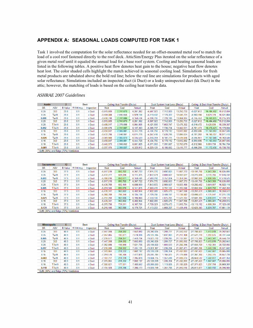
41
APPENDIX A: SEASONAL LOADS COMPUTED FOR TASK 1
Task 1 involved the computation for the solar reflectance needed for an offset-mounted metal roof to match the load of a cool roof fastened directly to the roof deck. AtticSim/Energy Plus iterated on the solar reflectance of a given metal roof until it equaled the annual load for a base roof system. Cooling and heating seasonal loads are listed in the following tables. A positive heat flow denotes heat gain to the house; negative heat flow denotes heat lost. The color shaded cells highlight the match achieved in seasonal cooling load. Simulations for fresh metal products are tabulated above the bold red line; below the red line are simulations for products with aged solar reflectance. Simulations included an inspected duct (ii Duct) or a leaky uninspected duct (kk Duct) in the attic; however, the matching of loads is based on the ceiling heat transfer data. ASHRAE 2007 Guidelines

42
ASHRAE 1980 Guidelines
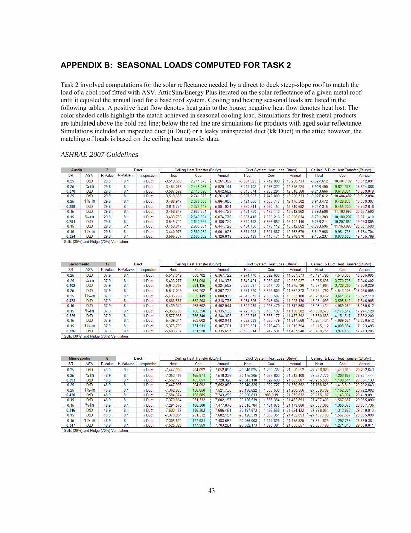
43
APPENDIX B: SEASONAL LOADS COMPUTED FOR TASK 2
Task 2 involved computations for the solar reflectance needed by a direct to deck steep-slope roof to match the load of a cool roof fitted with ASV. AtticSim/Energy Plus iterated on the solar reflectance of a given metal roof until it equaled the annual load for a base roof system. Cooling and heating seasonal loads are listed in the following tables. A positive heat flow denotes heat gain to the house; negative heat flow denotes heat lost. The color shaded cells highlight the match achieved in seasonal cooling load. Simulations for fresh metal products are tabulated above the bold red line; below the red line are simulations for products with aged solar reflectance. Simulations included an inspected duct (ii Duct) or a leaky uninspected duct (kk Duct) in the attic; however, the matching of loads is based on the ceiling heat transfer data. ASHRAE 2007 Guidelines
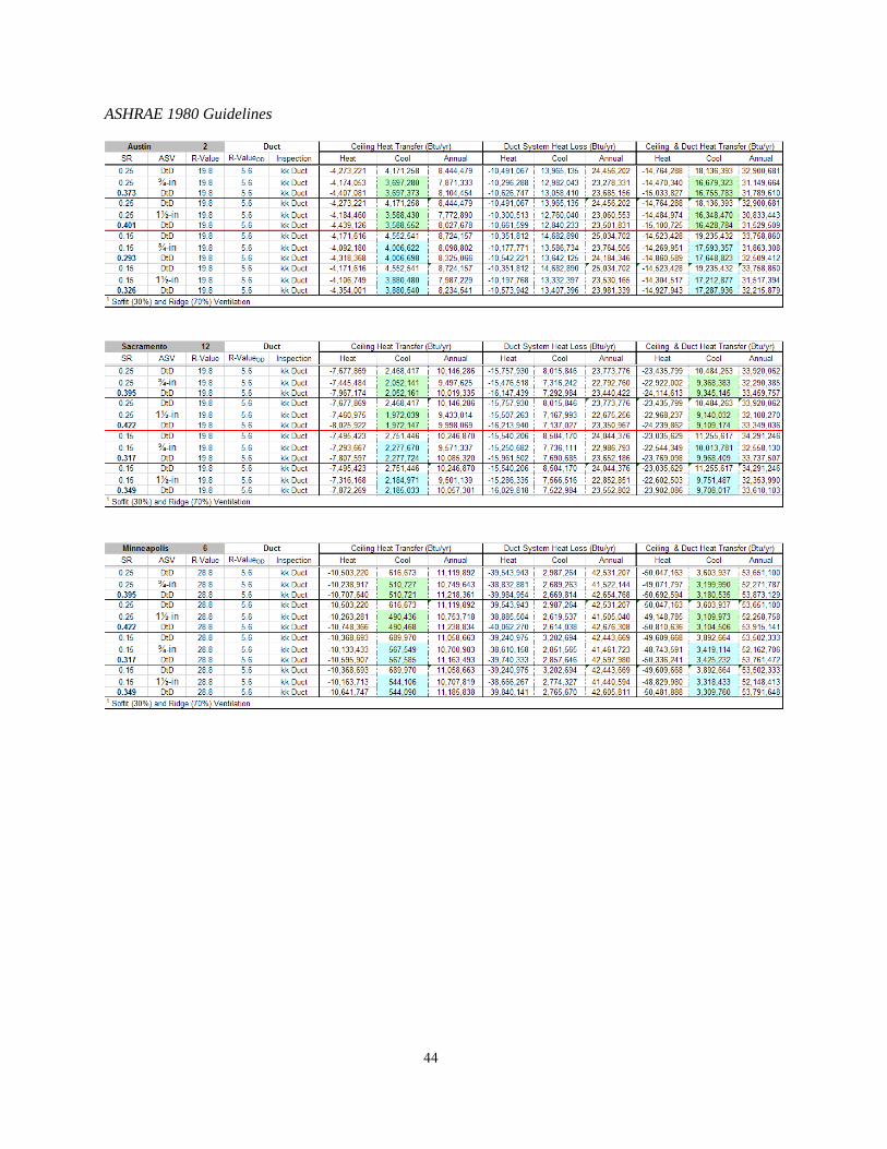
44
ASHRAE 1980 Guidelines
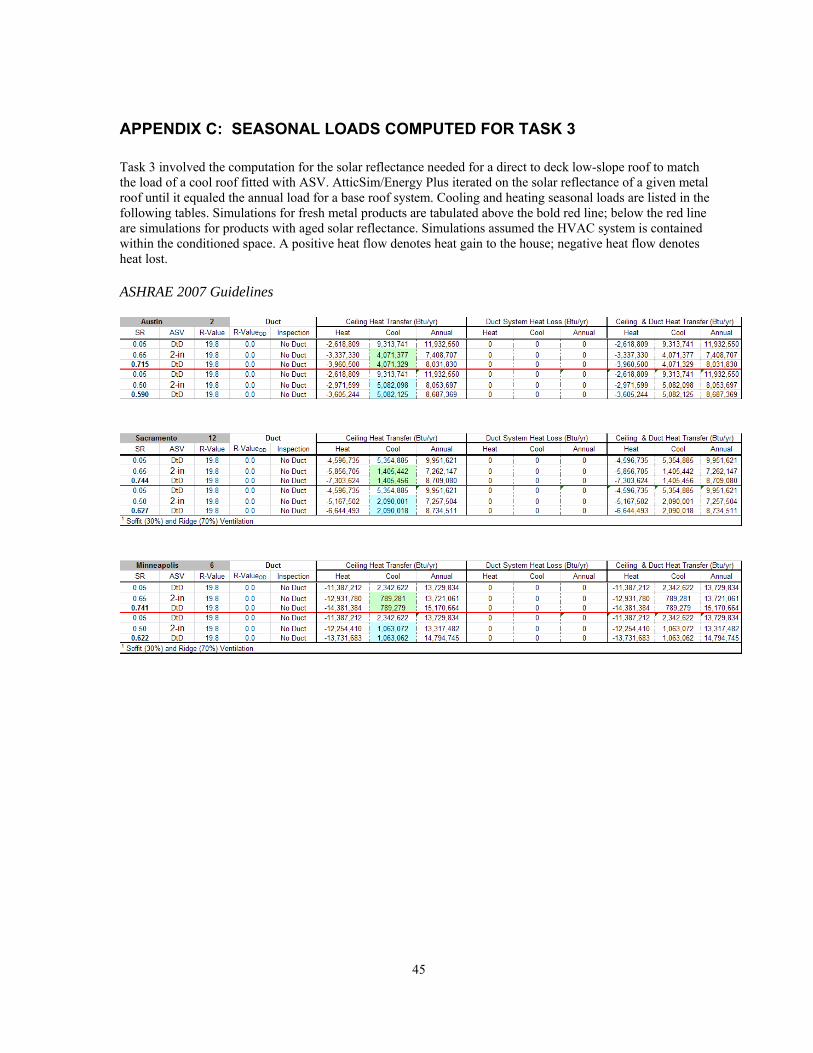
45
APPENDIX C: SEASONAL LOADS COMPUTED FOR TASK 3
Task 3 involved the computation for the solar reflectance needed for a direct to deck low-slope roof to match the load of a cool roof fitted with ASV. AtticSim/Energy Plus iterated on the solar reflectance of a given metal roof until it equaled the annual load for a base roof system. Cooling and heating seasonal loads are listed in the following tables. Simulations for fresh metal products are tabulated above the bold red line; below the red line are simulations for products with aged solar reflectance. Simulations assumed the HVAC system is contained within the conditioned space. A positive heat flow denotes heat gain to the house; negative heat flow denotes heat lost. ASHRAE 2007 Guidelines
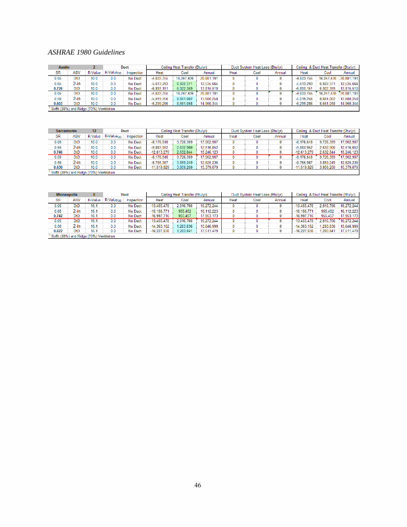
46
ASHRAE 1980 Guidelines