the tore supra cryogenic system design and … · the tore supra cryogenic system ... the tore...
TRANSCRIPT

1The Tore Supra cryogenic system P. Reynaud
TORE SUPRAAssociationEURATOM-CEA
MATEFU Spring school April 2009 Cadarache
THE TORE SUPRA CRYOGENIC SYSTEM
Design and operation
P.Reynaud
MATEFU Spring school April 2009 Cadarache

2The Tore Supra cryogenic system P. Reynaud
TORE SUPRAAssociationEURATOM-CEA
MATEFU Spring school April 2009 Cadarache
Outline
• Introduction : conception of the Tokamak
• Heat dissipations and constraints
• Design of the cryogenic system
• Operation of the cryogenic system
• Cryoplant availability
• Conclusion
The Tore Supra Cryogenic system

3The Tore Supra cryogenic system P. Reynaud
TORE SUPRAAssociationEURATOM-CEA
MATEFU Spring school April 2009 Cadarache
Thick casing
Conductor (NbTi, Cu, CuNi) 1.8K
Thin casing
Polyamide alumina chocks
Glass epoxy spacers
Supercritical heliumcooling channels 4.5K
Toroïdal field coil exploded view
• Average current density : 50A/mm²,
• 4.5 T on the plasma axis,
• 9 T Peak field on the conductor.
Conception of the Tokamak
• Tight envelop performed by the thin casing • Thick casing acting as: - mechanical reinforcement,- magnetic shield,- thermal shield.

4The Tore Supra cryogenic system P. Reynaud
TORE SUPRAAssociationEURATOM-CEA
MATEFU Spring school April 2009 Cadarache
Torus cross section
Plasma
External vacuum vessel (20°C)
External 80K thermal shield
Internal 80K thermal shield
Thick casing and winding pack (4.4 K and 1.8 K)
Internal vacuum vessel and first wall (120-200°C)
Conception of the Tokamak
All components are enclosed in a common vacuum vessel actively pumped

5The Tore Supra cryogenic system P. Reynaud
TORE SUPRAAssociationEURATOM-CEA
MATEFU Spring school April 2009 Cadarache
Torus assembly
Module of magnet/ thermal shield/ vacuum vessel
80K thermal shields
Conception of the Tokamak

6The Tore Supra cryogenic system P. Reynaud
TORE SUPRAAssociationEURATOM-CEA
MATEFU Spring school April 2009 Cadarache
Torus assembly
Conception of the Tokamak
Torus constituted by assembly of 6 modules of 3 coils
20t120t40 tMass
WindingsComponent ShieldsCasings

7The Tore Supra cryogenic system P. Reynaud
TORE SUPRAAssociationEURATOM-CEA
MATEFU Spring school April 2009 Cadarache
•Permanent losses
•Variable field losses
• Hysteretic losses α (DB)• Coupling losses α (dB/dt)2
windings
Insulating shocks
Wc
Normal shot (5kJ)
Plasma current disruption (15kJ)Low energythanks to efficient magnetic shielding
Low energythanks to efficient magnetic shielding
Fast discharge IT à 1250A (150kJ)
Winding pack heat loads
Heat dissipation and constraints

8The Tore Supra cryogenic system P. Reynaud
TORE SUPRAAssociationEURATOM-CEA
MATEFU Spring school April 2009 Cadarache
• variable field losses
• Permanent losses
= f (dIp/dt)2
Eddy currents
During the plasma shots (< 150kJ)
During the cleaning discharge (>= 1.MJ)
During the plasma current disruption (>= 1.2MJ)
Thickcasingwinding
Supportinglegs
Wc
Thick casing heat loads
Heat dissipation and constraints
9The Tore Supra cryogenic system P. Reynaud
TORE SUPRAAssociationEURATOM-CEA
MATEFU Spring school April 2009 Cadarache
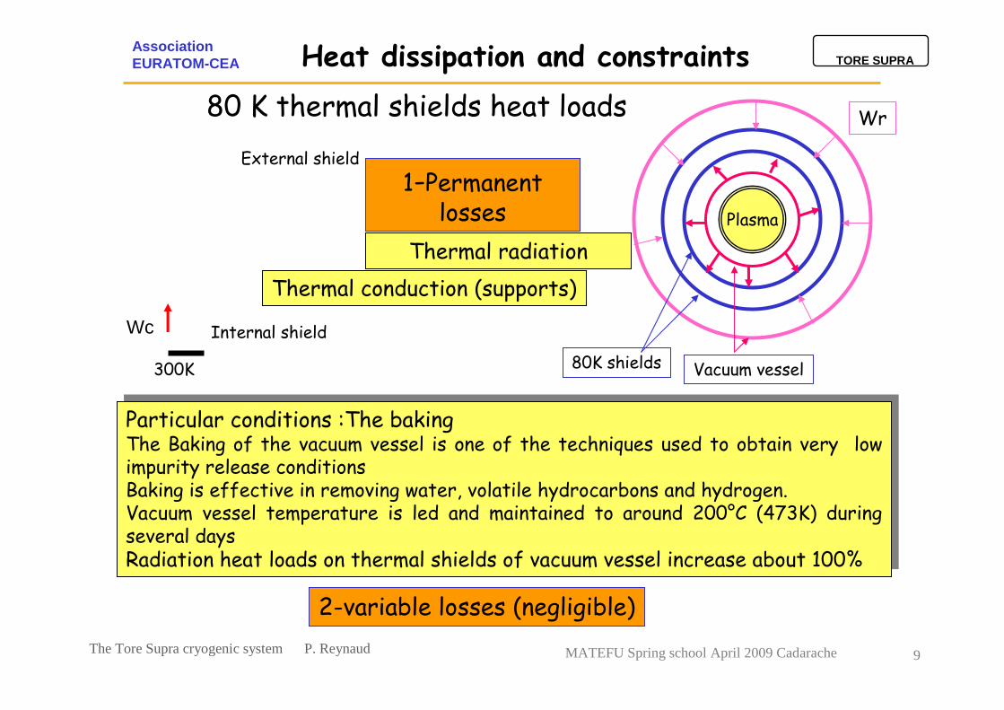
Thermal radiation
Thermal conduction (supports)
Particular conditions :The bakingThe Baking of the vacuum vessel is one of the techniques used to obtain very low impurity release conditions Baking is effective in removing water, volatile hydrocarbons and hydrogen.Vacuum vessel temperature is led and maintained to around 200°C (473K) during several daysRadiation heat loads on thermal shields of vacuum vessel increase about 100%
Particular conditions :The bakingThe Baking of the vacuum vessel is one of the techniques used to obtain very low impurity release conditions Baking is effective in removing water, volatile hydrocarbons and hydrogen.Vacuum vessel temperature is led and maintained to around 200°C (473K) during several daysRadiation heat loads on thermal shields of vacuum vessel increase about 100%
Wr
80K shields Vacuum vessel
Plasma
Internal shield
External shield
300K
Wc
1-Permanent losses
2-variable losses (negligible)
80 K thermal shields heat loads
Heat dissipation and constraints

10The Tore Supra cryogenic system P. Reynaud
TORE SUPRAAssociationEURATOM-CEA
MATEFU Spring school April 2009 Cadarache
20 kW--Static load(baking at 200°C)
12kW300 W120 to 160 WStatic load (vessel at 120°C)
-2 s1.5 / cycle2 s0.2 / cycle
Cleaning Discharge
-8 min40035 min235Fast Safety Discharge
-25 min120012 min50Disruptions
-4 min1204 min30PF cycle
Heat loadRecovery
timeHeat load
(kJ)Recovery
time
Heat load(kJ)
Transient load
80 K4.5K1.8 K
Summary of the design heat dissipations
Heat dissipation and constraints
The instantaneous power dissipated can be 10 times larger than average loads

11The Tore Supra cryogenic system P. Reynaud
TORE SUPRAAssociationEURATOM-CEA
MATEFU Spring school April 2009 Cadarache
Contraction of SS function of temperature
1000 mm
997 mm
DL/L=3mm/m
300K 80K
negligible
80K 4.5K
DL/L=0.1 mm/m
1000mm
999.9mm
Heat dissipation and constraints
Other constraints : the cool down• Major requirements are led by the differential contractions between materials function of temperature.
• Mechanical constraints during transients cooling down or warming up must be contained to avoid any plastic deformation of structures or between thick casing supports and thermal shields
• The contraction of materials is significant between 300K and 80K, therefore, between these values, the temperature gradient between any part of the system must be kept under 40K.
• To respect the previous requirement and to optimize the duration of the cool-down , the maximum speed rate of cooling down has been fixed at 2K/h to limit the temperature gradient between the thick casing and the centre of the windings
• In practice, the cool-down of the whole system from 300k to 1.8K takes around 15 days

12The Tore Supra cryogenic system P. Reynaud
TORE SUPRAAssociationEURATOM-CEA
MATEFU Spring school April 2009 Cadarache
• The Toroidal Superconducting Magnet at 1.8K (HeII bath) with comfortable margin,
• The thick casings at 4.5K (supercritical helium),
• The thermal shields at 80K (GHe),
Design of the cryogenic system
Summary of the design requirements- Providing the cold power to :
• Diagnostics, Neutral Beam test beds, Gyrotrons, Magnet Group test beds ..
- Liquefying helium and distributing LHe for the batch users :
- Ensuring a safe cool-down of the system following requirements on temperature gradients, with a reasonable duration,
- Using thermal storages, allowing the installed cold power to be lower than instantaneous heat loads,
- Including redundancies, to preserve the cold parts from fast divergences of temperatures in case of any failure of the system
- Adopting operational modes depending on plasma operation, for energy savings purpose.

13The Tore Supra cryogenic system P. Reynaud
TORE SUPRAAssociationEURATOM-CEA
MATEFU Spring school April 2009 Cadarache
W
Helium réfrigération : « Cycle de Claude »HP
BP13
14
1
2
113
4
9
H=cst
5
6
78
T
S7 ’
6 ’
H1
H2H3
W
1
2
3
4
5
6
78
9
10
11
12
13
W
JT valve
14
E1
E2
E3
E4
E5
C
6 ’
7 ’
Isenthalpic
Cold power = m ∆H = m(H8-H7)
Design of the cryogenic system
•The architecture of the refrigeration box is based on this thermo dynamical cycle
•The system sets to work a warm compression station, heat exchangers, turbo expanders, and expansion devices for the liquefaction.

14The Tore Supra cryogenic system P. Reynaud
TORE SUPRAAssociationEURATOM-CEA
MATEFU Spring school April 2009 Cadarache
He II refrigeration at 1.8K
Permanent losses = 120W
P installed = 300W
Available power180W
Design of the cryogenic system
W from 7 up to 17W / coil
2 circuits:• saturated He II• pressurized He II
windings
PF
P1-P2
LHe
HeII sat
C
He II 1.25b
1.75K - 13 mbCold source
Cold pumps
Warm ring pumps
Compression cycle
Heat exchanger
14g/s
•The windings are located in a static pressurized superfluid helium bath
•The refrigerating power is obtained by the means of evaporation by pumping

15The Tore Supra cryogenic system P. Reynaud
TORE SUPRAAssociationEURATOM-CEA
MATEFU Spring school April 2009 Cadarache
• No risk of air leakage• Easy helium transfer• Improvement of the coil stability• Increase of the critical current margin• High limiting flux, independent of immersion depth• All open and even recessed cavities are completely filled with liquid• Vapour can only appear with a high ∆T
Design of the cryogenic system
He II pressurized for coils
P (MPa)
T (K)Tλ=2.172 K
T= 4.2 KP= 0.1MPa
0.1
Helium phase diagram
T=1.8K
He II
He I

16The Tore Supra cryogenic system P. Reynaud
TORE SUPRAAssociationEURATOM-CEA
MATEFU Spring school April 2009 Cadarache
Design of the cryogenic system
The pumping on the He II bathes
The pumping on saturated bathes is performed in 2 parts:A cold part compresses in 2 stages 14g/s of helium gas from 12mbar at 4.3K up to 80mbar near 15K. At this pressure the helium is warmed to room temperature by standard heat exchangers.At room temperature the final compression from 70mbar could be performed by an oil ring pump.
The cold centrifugal compressors developed by L’AIR LIQUIDE run on magnetic bearings and are driven by variable speed drives developed by the S2M company.At the moment of the design of the cryogenic system, the use of this technology for this particular purpose for the first time in the world was a major breakthrough for the helium refrigeration and opened the way of larger refrigeration plants at 1.8K.
The choice of oil ring pump for the warm part of compression was also the result of comparatives studies both on technical aspects and economic costs.

17The Tore Supra cryogenic system P. Reynaud
TORE SUPRAAssociationEURATOM-CEA
MATEFU Spring school April 2009 Cadarache
The 4.5 K thick casing refrigerationDedicated power to cold source : P= 600W
Design of the cryogenic system
P
18 thick casings
W W
LHe
pump18 MPa4.5 K
17 bar4.5K
P,TThermal ballast
3000 LHe
P
C
PRefrigerator
Super critical He Circulation at Te = 4.5 K Refrigeration
box
Principle• Casings connected in series
• Supplied with SHe coming from cold box
• Fixed inlet temperature of casings
• Thermal ballasts filled with LHe
• Operation at V=cst
• Absorption and smoothing of the loads
• Refrigeration box with evaporation
• Compensation of liquid from external tank
Practically constant operation
Lhe restocking in off-peak hours
Optimization of the cold box size

18The Tore Supra cryogenic system P. Reynaud
TORE SUPRAAssociationEURATOM-CEA
MATEFU Spring school April 2009 Cadarache
Heat loads extracted from thick casings
HeII saturated bathes pressure
Thermal behavior during plasma operation
Design of the cryogenic system
8,5
9
9,5
10
10,5
11
11,5
07 08 09 10 11 12 13 14 15 16 17 18 19 20 21 22
Long plasma pulse 1 GJ
Plasma disruption and conditioning discharges
time (h)
Pressure (mbar)Toroidal field ramp up
200
400
600
800
1000
1200
1400
8 9 10 11 12 13 14 15 16 17 18 19 20 21
Plasma disruption and conditioning discharges
Long plasma pulse 1 GJ
time (h)
W
Toroidal field ramp up
19The Tore Supra cryogenic system P. Reynaud
TORE SUPRAAssociationEURATOM-CEA
MATEFU Spring school April 2009 Cadarache
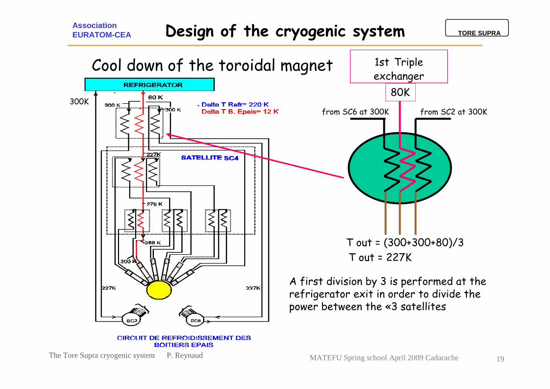
Cool down of the toroidal magnet
T out = 227K
from SC6 at 300K
80K
from SC2 at 300K
T out = (300+300+80)/3
1st Triple exchanger
Design of the cryogenic system
A first division by 3 is performed at therefrigerator exit in order to divide the power between the «3 satellites
300K

20The Tore Supra cryogenic system P. Reynaud
TORE SUPRAAssociationEURATOM-CEA
MATEFU Spring school April 2009 Cadarache
from SC6 at 300K
227Kfrom SC2 at 300K
T sortie = (300+300+227)/3
T sortie = 276K
2nd triple exchanger
Design of the cryogenic system
Cool down of the toroidal magnet
Within each satellite, a further division by 3 is operated
300K

21The Tore Supra cryogenic system P. Reynaud
TORE SUPRAAssociationEURATOM-CEA
MATEFU Spring school April 2009 Cadarache
300K from casing at 300K
276K
T sortie = (276+300)/2
T sortie = 288K
Double exchanger
CasingN°X300K 288K
∆T BEp=300-288=12K
(300-80)/18= 12
∆ T global refrigerator / 18
Design of the cryogenic system
Cool down of the toroidal magnet
Finally, divisions by 2 are accomplished

22The Tore Supra cryogenic system P. Reynaud
TORE SUPRAAssociationEURATOM-CEA
MATEFU Spring school April 2009 Cadarache
with T1+LN2 evaporation during baking
P = 30kW Increasing mass flow rate
P = 10kW
with T1 during normal operation
Available cold power from 2 sources
80 K thermal shields cooling loop
water
windings
Thermal shields
sat4sat6
First heatexchanger
CB
T1 turbine
Oil removal system
LN2
4.6 b18.6 b
18b
P
V1GHe circulation at
T = 80K
2 cold sourcesLN2 T1
80Ksat4sat6
sat2
Design of the cryogenic system

23The Tore Supra cryogenic system P. Reynaud
TORE SUPRAAssociationEURATOM-CEA
MATEFU Spring school April 2009 Cadarache
Design of the cryogenic system
Functional layout
Warm machine roomGathering warm compressors and pumpsIncluding Oil removal system
Providing the high pressure levels
Collecting low pressure levels
Cold boxProviding the 80K and the 4.5K levels
Liquefying helium Performing the cold pumping
Liquid helium storage
Cryogenic satellitesConnecting the different circuits
Performing the 1.8K source
Smoothing the heat loadsPart of the ∆T division
ColdBox
WarmMachines room
Torus Hall
Torus Hall

24The Tore Supra cryogenic system P. Reynaud
TORE SUPRAAssociationEURATOM-CEA
MATEFU Spring school April 2009 Cadarache
Compressor House• He screw compressors
• Oil removal systems
• He/H2O exchangers• Oil/H2O exchangers
• Oil ring pumps
• He Balloons• HP storage
• 200 bar compressors
• Coalescers
• Driers• Analysers
• He buffer tank
• Safety systems• Control &
instrumentation systems
Cryogenic Area• Cold box
• He/He Exchangers
• Gas bearing turbines• Expander engines
• Cold compressors
• 80 K GHe purifier• Charcoal adsorbers
• Analysers
• LN2 tanks
• LHe tank• Cryolines
• Vacuum systems
• Safety systems• Control &
instrumentation systems
Utilities• Vacuum system
• Water cooling systems
• Compressed air supply• Power supply
Overview of the components and utilities
Design of the cryogenic system

25The Tore Supra cryogenic system P. Reynaud
TORE SUPRAAssociationEURATOM-CEA
MATEFU Spring school April 2009 Cadarache
Rescue cold box• Including a single heat exchanger with a LN2 evaporator
• Included set of valves,
• Linked to the thermal shields by distinct circuits
Utilities• Vacuum system
• Water cooling systems : switchable on raw water circuits
• Compressed air supply from different sources
• Power supply from different sources
• Rescue Programmable Logic Controller
Redundancies
Design of the cryogenic system
Mainly aim to maintain the whole system under 80K,
A single cycle compressor is sufficient : 100g/s

26The Tore Supra cryogenic system P. Reynaud
TORE SUPRAAssociationEURATOM-CEA
MATEFU Spring school April 2009 Cadarache
• Within the Torus hall
- 3 colds boxes acting as cryogenic relays called cryogenic satellites,
- Each satellites contain a 1.8K source and a 4.5K thermal ballast,
- Each of satellites feeds 6 toroidal field coils,
- Each satellite is connected to the refrigerator by cryogenic lines
• Within the cryogenic hall
- The cold box
- A primary cryogenic line connected to the main cold box
• Adjoining the cryogenic hall
- 1 storage of 20m3 for LHe
- 2 storages of 50m3 each for LN2
• Within the warm machine hall( 70m from the cryogenic hall)
- The compressors and the warm pumps included in the system
- The recovery compressors
- Temporary helium storages: 200m3 and 400m3 gas bags
• Adjoining the warm machine hall
A high pressure storage (18MPa) of gaseous helium : total volume 70m3
Design of the cryogenic system
System layout

27The Tore Supra cryogenic system P. Reynaud
TORE SUPRAAssociationEURATOM-CEA
MATEFU Spring school April 2009 Cadarache
Cases and windings
Refrigerator cold box
20 000l Lhe tank
2*50 000l LN2 tankCompressorsand pumps station
200b Ghestorage
balloon GHe
Satellites
Cryogenic lines
Design of the cryogenic system
General overview

28The Tore Supra cryogenic system P. Reynaud
TORE SUPRAAssociationEURATOM-CEA
MATEFU Spring school April 2009 Cadarache
• First machine using a large quantity of superfluid helium
1m3 of saturated superfluid He, 4m3 of pressurized superfluid He
Cold Power at 3 levels of temperature
10 to 30 kW at 80 K
1000 W at 4.0K
300 W at 1.75K
• Electric consumed power in nominal operation : 1.2MW
• Mass at low temperature
20 000 kg at 80K shields
120 000 kg at 4.5 K thick casings
45 000 kg at 1.75 K conductors
• Cooling down duration 15 days to cool the magnet from 300 K to 1.75 K
• Fully automatic system with several operating modes for energy savings during short plasma shut down,
• 500 measurement loops, 300 cryogenic valves, 250 safety valves, 600 manual valves,
• 8 vacuum pumping systems,
• 7 Programmable Logic Controllers
The main figures
Design of the cryogenic system

29The Tore Supra cryogenic system P. Reynaud
TORE SUPRAAssociationEURATOM-CEA
MATEFU Spring school April 2009 Cadarache
Operation of the cryogenic system
Typical Plasma experimental campaign (2006)
Plasma Operation rhythm : ~ 40 hours a week4 days a week : TF magnet at 1.8K3 days at 4.2K week-end and maintenance day (Monday)Annual Shutdown : ~ 3 months a yearHeavy maintenances: Warm Compression Station for example,Regulatory controls for pressure equipments, power supplies ,etc…Tore Supra configuration changes, etc….
weeks
Temperature of the TF magnet
1
10
100
1000
0 2 4 6 8 10 12 14 16 18 20 22 24 26 28 30 32 34 36 38 40 42 44 46 48 50 52
week (year 2006)
Tem
per
atu
re (K
)
WINTER SHUTDOWN
WINTERSHUTDOWN
COMMISSIONING SUMMER CENTRE CLOSURE
IN-VESSEL WATER LEAK
EXPLOITATION PERIOD EXPLOITATION PERIOD
standbyat 4 K
standbyat 300 K
Heavy maintenance of the cryogenic
systems (4 weeks available per year)
Annual test of the auxiliary cold box
operationat 1.8 K

30The Tore Supra cryogenic system P. Reynaud
TORE SUPRAAssociationEURATOM-CEA
MATEFU Spring school April 2009 Cadarache
Operation of the cryogenic system
The cryoplant operational modes
Nominal operation
Liquefactionat 4 K
Warm stop
Liquefactiononly
Liquefactionat 80 K
Idle at 80 K
Liquefactionat 2 K
The more usual operational modes of the cryoplant

31The Tore Supra cryogenic system P. Reynaud
TORE SUPRAAssociationEURATOM-CEA
MATEFU Spring school April 2009 Cadarache
Time spent in the different operating modes trough years
100 %8760 h100 %8760 h100 %8760 h100 %8784 hTOTAL
28 %2440 h16 %1394 h17 %1518 h23 %2013 hTotal time spent in
transitions
28 %2445 h28 %2495 h23 %2036 h20%1770 hNominal operation
confirmed
0 %0 h0 %0 h0 %0 h2 %177 hLiquefaction at 2 K confirmed
17 %1512 h43%3645 h22 %1893 h21 %1841 hLiquefaction at 4 K confirmed
5 %399 h1 %89 h6 %558 h6 %501 hLiquefaction at 80 K confirmed
2%192 h2 %192 h7 %577 h3 %222 hLiquefaction at 300K
confirmed
5 %421 h4 %338 h10 %853 h5 %476 hIdle at 80 K confirmed
15%1342 h6 %543 h15 %1311 h20 %1732 hWarm stop confirmed
totalshourstotalshoursTotalshourstotalshoursOperating mode
2007200620052004
Cryoplant availability

32The Tore Supra cryogenic system P. Reynaud
TORE SUPRAAssociationEURATOM-CEA
MATEFU Spring school April 2009 Cadarache
28 %2445 h28 %2495 h23 %2036 h20%1770 hNominal operationconfirmed
totalhourstotalhourstotalhourstotalhoursOperating mode
2007200620052004
80 %76 %54 %53 %
Availability of the whole Tore
Supra installation
97.3 %100 %92.9 %76.2 %Availability of the cryogenic
system**
Relative availability to the plasma experimental campaign
Cryoplant availability
** Relatively to experimental campaign

33The Tore Supra cryogenic system P. Reynaud
TORE SUPRAAssociationEURATOM-CEA
MATEFU Spring school April 2009 Cadarache
Tore Supra Cryoplant events
• Cold components: expanders, cold compressors, valves, exchangers.
• Instrumentation: Probe and signal conditioning.
• Process control: Hardware and software, process application
• Utilities: Water cooling, compressed air, power supplies, vacuum.
• Operation: He analysis and purification, the other faults.
• Warm components: compressors, pumps, valves, driers, ….
0%
5%
10%
15%
20%
25%
30%
Cold component
Instrumentation
Process controlUtiliti
es
Operation
Warm component
Cryoplant availability
Distribution of faults during the cryoplant operation over the last 3 years 2004-2007

34The Tore Supra cryogenic system P. Reynaud
TORE SUPRAAssociationEURATOM-CEA
MATEFU Spring school April 2009 Cadarache
Cryogenics• Clogging of 80K stage exchanger of the cold box : addition of an external purifier
• Tightness breaking of Al/SS junction of thick casing circuit inside a cryoline,
• Many gaseous helium leaks : installation of a recorded helium leak detector,
• Water in oil circuits of the warm compressors in 2005,
• Pollution of the coils circuits during the cool-down in 2008,
Utilities• Very short life span of the compressor motors bearings at the beginning,
• Inappropriate system of command-control replaced by industrial PLC later
• Corrosion on water cooled black steel exchangers in the warm machine room,
• Corrosion and water leaks on vacuum diffusion pumps circuits,
• 2 total electric shutdown in the 4 last years : rescue by Electrical Mobile Groups
Main troubles encountered through years
Cryoplant availability

35The Tore Supra cryogenic system P. Reynaud
TORE SUPRAAssociationEURATOM-CEA
MATEFU Spring school April 2009 Cadarache
The conception of the Tore Supra cryogenic system at the end of the 70’s was
the result of studies lead by CEA about design and sizing of 1.8K refrigeration
circuits.
More than 20 years after its commissioning, and without any large updating, the
cryogenic system is operated in quasi-industrial conditions with a satisfying level
of performance and availability.
Keeping a human presence on the site, performing daily inspections of the
critical components and a reliable and ergonomic control-command system make
possible an increase of availability during the 4 last years.
Total operating time at low temperature
140 000 h including 57 000 h at T = 1.8K
Conclusion

36The Tore Supra cryogenic system P. Reynaud
TORE SUPRAAssociationEURATOM-CEA
MATEFU Spring school April 2009 Cadarache
Flow rate
14g/s
Compression ratio 2.3
Suction conditions
34mb/10K
Cold compressor PF2
AL/S2M
Flow rate
10g/s
In/out Pressure
18/1.2bar
In/out Temperature 6/4.5K
Wet reciprocating engine
AL/KPS model 1400
Flow rate50g/s
Power2.2kW
In/out Temperature 19/10K
Turbine T3AL C4-500
Flow rate
24g/s
Power
2.8kW
In/out Temperature 50/30K
Turbine T2
AL C3-500
20000l of LHe + 2 x 50000l of LN2Liquid storages
Flow rate
14g/s
Compression ratio 3Suction conditions
10mb/4.5K
Cold compressor PF1
AL/S2M
Flow rate110g/s
Power16kW
In/out Temperature 110/80K
Turbine T1AL C5-500
Extra-slide
Technical specifications of cold components

37The Tore Supra cryogenic system P. Reynaud
TORE SUPRAAssociationEURATOM-CEA
MATEFU Spring school April 2009 Cadarache
Whole capacity : 1500kgPressure max
200bars
HP storage
160m3 + 360m3Gas bags
Electrical power of motor 132kW
Flow rate
60g/s
In/out Pressure
0.6/1bar
Oil ring pump P2
Alstom Hydro PL 50
Electrical power of motor
90kW
Flow rate
10g/s
Pressure max
200 bar
Recovery compressor C7
Sulzer type C5U
Electrical power of motor
75kW
Flow rate
10g/s
Pressure max
200bar
Recovery compressor C8
Sulzer type C5U
Electrical power of motor
400kW
Flow rate
218g/s
In/out Pressure
4.5/18bar
Compressor C4
STAL S57
Electrical power of motor
250kW
Flow rate
144g/s
In/out Pressure
4.5/18bar
Compressor C3
STAL S51
Electrical power of motor
200kW
Flow rate
101g/s
In/out Pressure
1/4.5bar
Compressor C2
STAL S73
Electrical power of motor 315kW
Flow rate
14 g/s
In/out Pressure 70/600mbar
Oil ring pump P1
Alstom Hydro PL 160
Electrical power of motor
200kW
Flow rate
101g/s
In/out Pressure
1/4.5bar
Compressor C1
STAL S7
Extra-slide
Technical specifications of warm components