the thermal sieve: a diffractive ba ffle that provides thermal
TRANSCRIPT

The Thermal Sieve: a diffractive baffle that provides thermal isolation of a cryogenic optical system from an ambient temperature collimator
James H. Burge* and Dae Wook Kim
College of Optical Sciences
University of Arizona Tucson, AZ USA 85721
ABSTRACT
We present the thermal sieve, which is a diffractive baffle that provides thermal isolation between an ambient collimator and a cryogenic optical system being measured. The baffle uses several parallel plates with holes in them. The holes are lined up to allow the collimated light to pass, but the view factor for thermal radiation is greatly reduced. A particular design is shown here that allows less than 0.25 W/m2 thermal transfer and degrades the test wavefront by only 3 nm rms.
Keywords: Space optics, collimator, cryogenic testing
1. INTRODUCTION Optical imaging systems are being built that operate in cold space or in very cold climates, such as Antarctica. It is seldom practical to test such systems in their final operational environment. Systems that operate at ambient temperatures are commonly tested using collimators that feed the imaging system with light that appears to come from far away. But the thermal gradients caused by exposing a cryogenic system to an ambient temperature collimator will create large distortions and make testing difficult. For cases where the system being tested must operate at cold temperatures, several options available are shown in Table 1.
The difficulty of optical testing for cryogenic systems arises because of the following aspects of the systems:
• The operational systems will have degraded performance at ambient temperatures. They are designed to operate cold.
• The operational systems are sensitive to thermal conditions. Radiation from an ambient temperature object will induce thermal gradients that degrade the system performance.
• The collimators or test optics themselves are sensitive to thermal conditions. Radiation to a cryogenically cooled surface will induce thermal gradients that degrade performance.
• Any test of high performance systems must use optics to create wavefronts that are nearly perfect. Otherwise, errors in the test optics will limit the ability to measure the performance of the imaging system under test.
Space Telescopes and Instrumentation 2012: Optical, Infrared, and Millimeter Wave, edited by Mark C. Clampin,Giovanni G. Fazio, Howard A. MacEwen, Jacobus M. Oschmann, Jr., Proc. of SPIE Vol. 8442, 84421L
© 2012 SPIE · CCC code: 0277-786/12/$18 · doi: 10.1117/12.927789
Proc. of SPIE Vol. 8442 84421L-1
Downloaded From: http://spiedigitallibrary.org/ on 10/19/2012 Terms of Use: http://spiedl.org/terms

Table 1. Options available for testing cryogenic optical imaging systems
Concept Comments
Cryogenic optics are very expensive and risky. A full aperture cryogenic collimator could cost as much as the system that it is measuring.
It would be difficult to verify the performance of the collimator.
An alternative is testing with a full aperture autocollimating flat. Control of the figure of the flat at temperature is expensive and risky.1
A large aperture, high quality window is expensive.
The window is difficult to calibrate.
It is difficult to provide thermal isolation, yet allow light to pass.
Most small systems are tested this way.
Subaperture testing + stitching Allows use of smaller window or test system
Smaller test allows the use of a smaller window, or smaller optics that must operate cold.
Multiple overlapping measurements can be “stitched” to provide full aperture data.
Data acquisition can be cumbersome.
Subject to noise and variations during the testing
Quantify performance by analysis Rely on combination of component testing and modeling
For systems with active controls, a full aperture measurement may not be required.2
For the ideal case, an ambient temperature collimator, such as LOTIS3, can be used for measuring a large cryogenic system. This can be accomplished with a thermal sieve that allows the test light to pass, yet limits the heat transfer from radiative coupling. This is accomplished using plates that have holes in them, with the holes lined up to pass the collimated test light, but the holes small enough to limit the view factor for heat transfer.
The thermal sieve (TS) is placed between the collimator and the optical system under test as shown in Fig. 1 (right). There are four major design parameters for a TS; i) N: Number of thermal plates, ii) S: Spacing between the thermal plates, iii) Dhole: hole diameter, and iv) I: Interval between holes. The concepts of the thermal sieve, and an example design are provided here, and some engineering details are given in a recent publication from the authors.4 Much of the material in the current paper is drawn directly from Reference 4.
Use a cryogenic collimator
Test through a window
Proc. of SPIE Vol. 8442 84421L-2
Downloaded From: http://spiedigitallibrary.org/ on 10/19/2012 Terms of Use: http://spiedl.org/terms
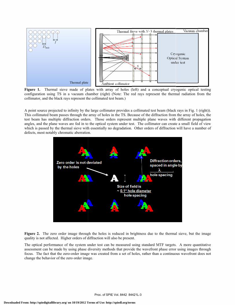
Figure 1. configurationcollimator, an
A point sourcThis collimattest beam haangles, and twhich is passdefects, most
Figure 2. Tquality is not
The optical passessment cfocus. The fchange the b
Thermal sieven using TS innd the black ra
ce projected toted beam passeas multiple dithe plane wavesed by the thert notably chrom
The zero ordert affected. Hig
performance ocan be made byfact that the zeehavior of the
e made of pln a vacuum chays represent th
o infinity by thes through the ffraction order
es are fed in tormal sieve withmatic aberratio
r image througgher orders of d
of the system uy using phase dero-order imagzero order ima
lates with arrahamber (right)he collimated t
he large collimaarray of holes
rs. Those ordo the optical syh essentially n
on.
gh the holes isdiffraction will
under test can diversity methe was created
age.
ay of holes ( (Note: The rest beam.)
ator provides a in the TS. Becders represent ystem under teso degradation.
s reduced in bl also be presen
be measured hods that provid
from a set of h
(left) and a cred rays repre
a collimated tescause of the dimultiple plan
st. The collim Other orders
brightness due nt.
using standardde the wavefroholes, rather th
onceptual crysent the therm
st beam (blackiffraction fromne waves withmator can create
of diffraction
to the therma
d MTF targetsont phase errorhan a continuo
ogenic opticalmal radiation f
k rays in Fig. 1 m the array of h
different prope a small fieldwill have a nu
al sieve, but th
. A more quar using images ous wavefront
l testing from the
(right)). holes, the pagation
d of view umber of
he image
antitative through
does not
Proc. of SPIE Vol. 8442 84421L-3
Downloaded From: http://spiedigitallibrary.org/ on 10/19/2012 Terms of Use: http://spiedl.org/terms

2. THERMAL DESIGN The radiative heat transfer relationships for a thermal sieve were developed to determine the flow of thermal energy from one space to another. The thermal transfer between the plates is defined by the emissivity and temperature of the plates and the relatively small area encompassed by the holes. The problem is simplified by ignoring edge effects, assuming infinite plates with holes defined only by the fractional area. The collimator and optical system spaces are represented by two blackbodies with their operating temperatures TH and TC. The thermal plates are modeled as graybodies with controlled temperatures T1-3 and emissivity ε1-3 values, corresponding to the 1st, 2nd, and 3rd plates . The emissive power J from these graybodies is given from Stefan-Boltzmann law
]/[ 24 mWTJ ⋅⋅= σε . (Eq. 1)
where ε is the emissivity, σ is the Stefan-Boltzmann constant 5.67x10⁻⁸ W/m2/K4, and T is the absolute temperature of the graybody.
Figure 3. Thermal transfer model with three thermal plates in a vacuum chamber. The solid arrows represent the net directional thermal flux in each space. Also, as an example, four emissive power components contributing to Jnet_2- are depicted as dotted arrows 1-4. (1) Graybody radiation from the 2nd thermal plate, (2) Reflection of Jnet_2+ by the 2nd thermal plate, (3) Leak of Jnet_3- through the 2nd plate holes except the power directly passes through the 1st plate holes, and (4) Leak of Jnet_4- through the 3rd and 2nd plate holes except the power directly passes through the 1st plate holes.
A set of interconnected steady state thermal transfer equations is defined for each space using thermal radiation and geometry. For instance, the net power Jnet_2- can be found as a sum of the contributions, shown as dotted arrows in Fig. 3. The thermal transfer equation becomes
4
_ 2 2 2
_ 2 2
1_3
1 2_ 4
: (1) .3.
(1 ) : (2) .3.
( )(1 ) : (3) .3.
( )(1 ) : (4) .3.
net
net
effnet
eff effnet
J T in Fig
J in Fig
J in Fig
J in Fig
ε σ α
ε α
πα
π
απ
−
+
−
−
= ⋅ ⋅ ⋅
+ ⋅ − ⋅
−Ω+ ⋅ ⋅ −
Ω −Ω+ ⋅ ⋅ −
.
(Eq. 2)
Proc. of SPIE Vol. 8442 84421L-4
Downloaded From: http://spiedigitallibrary.org/ on 10/19/2012 Terms of Use: http://spiedl.org/terms

where the obscuration ratio α of each thermal plate was defined as the ratio of the not-a-hole region area to the whole thermal plate area. Two effective solid angle Ωeff1 and Ωeff2 represent the sum of solid angles encompassed by the array of holes in the neighboring plate (S away) and the following plate (2S away), respectively. These solid angles are expressed using approximated projected solid angles with cos4θ scale factor as
∑∑∞
==
∞
== ++
+⋅
=+⋅
≅Ω
01
4
22222
2
01
42
2
1 ))(
(414
)cos41()2/(
mn
hole
mn
holeeff
mnIS
SSD
SD π
θπ . (Eq. 3)
and
∑∑∞
==
∞
== ++
+⋅
=+⋅
≅Ω
01
4
22222
2
01
42
2
2 ))(
(4116
)cos41()2(
)2/(
mn
hole
mn
holeeff
mnIS
SS
DS
D πθ
π . (Eq. 4)
where θ is the angle shown in Fig. 3. The n and m represent the relative column and row differences between two holes in the thermal plates as depicted in Fig. 3. Infinite number of holes (i.e. infinite n and m) was assumed instead of using the actual number of the holes. This eliminates the geometrical asymmetry problem (e.g. edge effect) for evaluating the effective solid angles not at the center of thermal plate.
A similar analysis was performed for the other spaces for a 3-plate system, resulting in a set of inter-related transfer equations. These are expressed in matrix form as
⎥⎥⎥⎥⎥⎥⎥⎥⎥⎥⎥
⎦
⎤
⎢⎢⎢⎢⎢⎢⎢⎢⎢⎢⎢
⎣
⎡
=
⎥⎥⎥⎥⎥⎥⎥⎥⎥⎥⎥
⎦
⎤
⎢⎢⎢⎢⎢⎢⎢⎢⎢⎢⎢
⎣
⎡
⎥⎥⎥⎥⎥⎥⎥⎥⎥⎥⎥
⎦
⎤
⎢⎢⎢⎢⎢⎢⎢⎢⎢⎢⎢
⎣
⎡
−−−Ω−Ω−Ω−−
−−Ω−−Ω−Ω−Ω−Ω−Ω−−
−−Ω−−Ω−Ω−−
−
+
−
+
−
+
−
+
4
433
433
422
422
411
411
4
4_
4_
3_
3_
2_
2_
1_
1_
312
13
2121
2112
11
211
10000000)1(10)1(0/)1(0/)1(
/)1)((01)1(000000)1(10/)1)((0/)1)((
/)1)((0/)1)((01)1(000000)1(10/)1)((
/)1(0/)1(0)1(01)1(00000001
C
H
net
net
net
net
net
net
net
net
effeff
eff
effeffeff
effeffeff
eff
effeff
TTTTTTTT
JJJJJJJJ
σασεασεασεασεασεασε
σ
αεαπαπαπαπαε
αεπαππαπαπαπαε
αεπαππαπαααε (Eq.5)
in terms of the given emissivity values ε1-3, absolute temperature of the thermal plates T1-3, temperature of the hot collimator space TH, temperature of the cold optical system space TC, and the obscuration ratio of the thermal plate α. The effective solid angle Ωeff1 and Ωeff2 were given in Eq. (3) and (4).
By solving Eq. (5) using an inverse matrix calculation, the net emissive power J values are determined. The thermal loads to the optical system space ΔJC and the collimator space ΔJH are given as
−+ −=Δ 4_4_ netnetC JJJ (Eq. 6)
+− −=Δ 1_1_ netnetH JJJ (Eq. 7) where Jnet_1± and Jnet_4± are depicted in Fig. 3. A positive thermal load means incoming thermal energy to the space, and a negative value means outgoing thermal energy from the space. The thermal flux for each space can be solved by numerically inverting the matrix in Eq. 5. This was performed for the case listed below in Table 2.
Table 2. Parameters of a thermal sieve
Parameters Symbol Value Diameter of a hole Dhole 0.002 m Interval between holes I 0.02 m Spacing between plates S 0.25 m Number of thermal plates N 3 Wavelength λ 1µm
Proc. of SPIE Vol. 8442 84421L-5
Downloaded From: http://spiedigitallibrary.org/ on 10/19/2012 Terms of Use: http://spiedl.org/terms
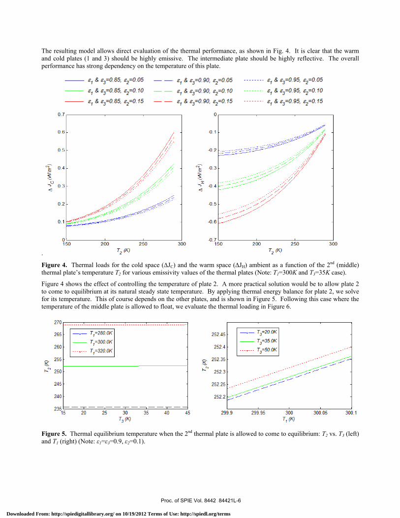
The resulting model allows direct evaluation of the thermal performance, as shown in Fig. 4. It is clear that the warm and cold plates (1 and 3) should be highly emissive. The intermediate plate should be highly reflective. The overall performance has strong dependency on the temperature of this plate.
.
Figure 4. Thermal loads for the cold space (ΔJC) and the warm space (ΔJH) ambient as a function of the 2nd (middle) thermal plate’s temperature T2 for various emissivity values of the thermal plates (Note: T1=300K and T3=35K case).
Figure 4 shows the effect of controlling the temperature of plate 2. A more practical solution would be to allow plate 2 to come to equilibrium at its natural steady state temperature. By applying thermal energy balance for plate 2, we solve for its temperature. This of course depends on the other plates, and is shown in Figure 5. Following this case where the temperature of the middle plate is allowed to float, we evaluate the thermal loading in Figure 6.
Figure 5. Thermal equilibrium temperature when the 2nd thermal plate is allowed to come to equilibrium: T2 vs. T3 (left) and T1 (right) (Note: ε1=ε3=0.9, ε2=0.1).
Proc. of SPIE Vol. 8442 84421L-6
Downloaded From: http://spiedigitallibrary.org/ on 10/19/2012 Terms of Use: http://spiedl.org/terms

Figure 6. Thermal analysis of system with T2 allowed to float: Thermal loads to the cold optical system space ΔJC (left) and the hot collimator space ΔJH (right) (Note: ε1=ε3=0.9, ε2=0.1).
The thermal modeling was verified with an independent numerical simulation using the Zemax non-sequential ray tracing program. The Zemax model was configured in a way that each surface emits, absorbs, reflects, or scatters rays according to the appropriate temperature and emissivity. The results, shown below in Figure 7, provide corroboration in the thermal model.
Figure 7. Comparison between the analytical thermal transfer model and Zemax numerical simulations using non-sequential ray tracing (for T1=300K, T2=252K, T3=35K and ε1=ε3=0.9, ε2=0.1 case).
3. ANALYSIS OF OPTICAL PERFORMANCE The thermal sieve blocks the radiative transfer, but allows collimated light to pass as long as the holes are aligned with the geometric propagation of the light. But a diffraction effect due to misalignments can create aberrations in the collimated light. These are evaluated below, for the case of 1µm wavelength and a thermal sieve made of 3 plates with 2 mm holes, 20 mm hole spacing, and 250 mm plate separation.
A diffraction model was constructed to evaluate the propagation of the light as it goes though the holes. The intensity of the light as it passes through the series of ideal holes is shown in Figure 8. The diffraction effects are more interesting when the holes are not perfectly aligned, or have irregular sizes. The effect of these variations causes the diffracted light to have slightly different mean complex amplitude, which will appear as aberrations in the final imaging system.
Proc. of SPIE Vol. 8442 84421L-7
Downloaded From: http://spiedigitallibrary.org/ on 10/19/2012 Terms of Use: http://spiedl.org/terms

Figure 8. As the light propagates, the diffraction from one hole interacts with the next. This is modeled for ideal holes on thin plate.
.
Figure 9. The complex amplitude of the light as it exits the hole in plate 3 will have some amplitude and phase variations due to non-ideal holes. The amplitude and phase are compared for an ideal case, and for a system with 70 µm hole shift and 20 µm diameter variation.
The amplitude and phase of the wavefront that constructs the final image in the system under test is defined by the amplitude and phase of the light as is exits the hole in the last plate. Variations in amplitude are benign, and can be easily calibrated. Variations in phase appear as optical aberrations, and limit the accuracy of the test. A Monte Carlol analysis was performed to investigate the sensitivities. The results, shown in Figure 10, demonstrate that tolerances > 100 µm can be used, yet the diffraction effects will degrade the system wavefront phase by less than 0.003 waves rms.
Proc. of SPIE Vol. 8442 84421L-8
Downloaded From: http://spiedigitallibrary.org/ on 10/19/2012 Terms of Use: http://spiedl.org/terms

Figure 10. Vis used for ca
The thermal test optics. Tis virtually uwavefront ac
The hole intework is requContinued wthe edges, req
1) R. Brow
Proc. SP2) Barto, A
(2008). 3) S. C. We
the Larg4) D. Kim,
Express
Variations in halibration. The
sieve can provThe thermal leaunaffected. Evccuracy of 0.00
erval and size,uired to unde
work is requiredquire developm
wn and D. ChanPIE 4198 (2001A.A., et al., “Op
est, S. H. Bailege Optics Test a
W. Cai, and J.20, 12378-123
hole size and pe sensitivities s
vide excellent akage for a simven with realist03 waves.
, and the platerstand the tra
d to build and ament of a testbe
ney, “Optomech1). ptical performa
ey, J. H. Burgeand Integration. H. Burge, “U392 (2012).
lacement haveshown here are
4. Dthermal isolati
mple 3-plate systic manufactur
e spacing wereadeoffs and toassess a practiced to test the id
REF
hanical tests an
ance verificatio
, B. Cuerden, Jn Site (LOTIS)
Use of thermal s
e an effect on t for 2 mm hole
DISCUSSIOion between a stem is on the ring and assem
e chosen somewo optimize thecal thermal sievdeas and to qua
FERENCES
nd performanc
on of the James
J. Hagen, H. M) 6.5m Collimasieve to allow o
the amplitude aes, 25 cm plate
N cryogenic optiorder of 0.25 W
mbly tolerances
what arbitrarilyese parametersve. The interfaantify the manu
e results of the
s Webb Space
M. Martin, and Mator,” Appl. Opoptical testing
and phase of the spacing, and 1
ical system anW/m2. Yet thes, the system is
y for this prelis for some space issues for tufacturing trad
e SIRTF cryoge
Telescope”, Pr
M. T. Tuell, “Wpt. 49, 3522-35of cryogenic o
he zero-order l1 µm waveleng
d ambient teme transmitted ws expected to m
iminary study.pecific test conthe plates, espe
deoffs.
enic optical sy
roc. SPIE 7010
Wavefront con37 (2010).
optical systems
light that gth. .
mperature wavefront
maintain
. Future nditions. ecially at
stem,”
0,
trol of
,” Opt.
Proc. of SPIE Vol. 8442 84421L-9
Downloaded From: http://spiedigitallibrary.org/ on 10/19/2012 Terms of Use: http://spiedl.org/terms