the the slot hoisting anchor system - pretec as · t-slot-lifting system a 2/32 doc. №: 32000...
TRANSCRIPT
TECHNICAL SPECIFICATION
T-Slot-lifting system
A 1/32 Doc. №: 32000 Date:17-10-05
The T-slot lifting anchor system
The T-slot lifting anchor system........................................................................................................1 Introduction .......................................................................................................................................2 The T-slot anchor..............................................................................................................................3 The O-anchor....................................................................................................................................3 The P-anchor ....................................................................................................................................3 The TKS rod-anchor .........................................................................................................................3 The TPA plate-anchor ......................................................................................................................3 The TKA tilting -anchor.....................................................................................................................3 The TSG bended T slot anchor ........................................................................................................3 Characteristics ..................................................................................................................................3
T slot anchor .................................................................................................................................3 P anchor........................................................................................................................................3 O anchor .......................................................................................................................................3 The TKA tilting-anchor ..................................................................................................................3 TKS Anchor...................................................................................................................................3
The TH 2 lifting hook.........................................................................................................................3 Lifting under a angle .....................................................................................................................3 Checking measurements by reasons of wear to the lifting hook ..................................................3
Attachment of the lifting anchors in the concrete .............................................................................3 The ball socket RB........................................................................................................................3 The SRB-socket ............................................................................................................................3 Ball socket SB...............................................................................................................................3 RR ring ..........................................................................................................................................3 RBP socket ...................................................................................................................................3
Calculation of the T slot anchor ........................................................................................................3 Lifting in an angle..........................................................................................................................3 Dynamic forces .............................................................................................................................3 Directions for stick factors.............................................................................................................3
Anchoring of T slot anchors..............................................................................................................3 Calculation example 1 ......................................................................................................................3 Table 1..............................................................................................................................................3 Calculation example 2 ......................................................................................................................3 Table 2..............................................................................................................................................3 Calculation example 3 ......................................................................................................................3 Table 3..............................................................................................................................................3 Calculation example 4 ......................................................................................................................3 Table 4..............................................................................................................................................3 Threat analysis .................................................................................................................................3
TECHNICAL SPECIFICATION
T-Slot-lifting system
A 2/32 Doc. №: 32000 Date:17-10-05
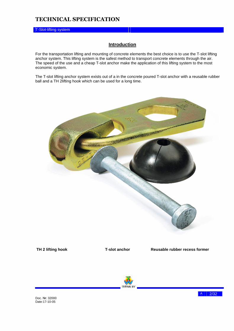
Introduction For the transportation lifting and mounting of concrete elements the best choice is to use the T-slot lifting anchor system. This lifting system is the safest method to transport concrete elements through the air. The speed of the use and a cheap T-slot anchor make the application of this lifting system to the most economic system. The T-slot lifting anchor system exists out of a in the concrete poured T-slot anchor with a reusable rubber ball and a TH 2lifting hook which can be used for a long time.
TH 2 lifting hook T-slot anchor Reusable rubber recess former
TECHNICAL SPECIFICATION
T-Slot-lifting system
A 3/32 Doc. №: 32000 Date:17-10-05
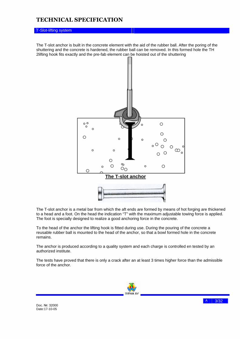
The T-slot anchor is built in the concrete element with the aid of the rubber ball. After the poring of the shuttering and the concrete is hardened, the rubber ball can be removed. In this formed hole the TH 2lifting hook fits exactly and the pre-fab element can be hoisted out of the shuttering
The T-slot anchor
The T-slot anchor is a metal bar from which the aft ends are formed by means of hot forging are thickened to a head and a foot. On the head the indication “T” with the maximum adjustable towing force is applied. The foot is specially designed to realize a good anchoring force in the concrete. To the head of the anchor the lifting hook is fitted during use. During the pouring of the concrete a reusable rubber ball is mounted to the head of the anchor, so that a bowl formed hole in the concrete remains. The anchor is produced according to a quality system and each charge is controlled en tested by an authorized institute. The tests have proved that there is only a crack after an at least 3 times higher force than the admissible force of the anchor.
TECHNICAL SPECIFICATION
T-Slot-lifting system
A 4/32 Doc. №: 32000 Date:17-10-05
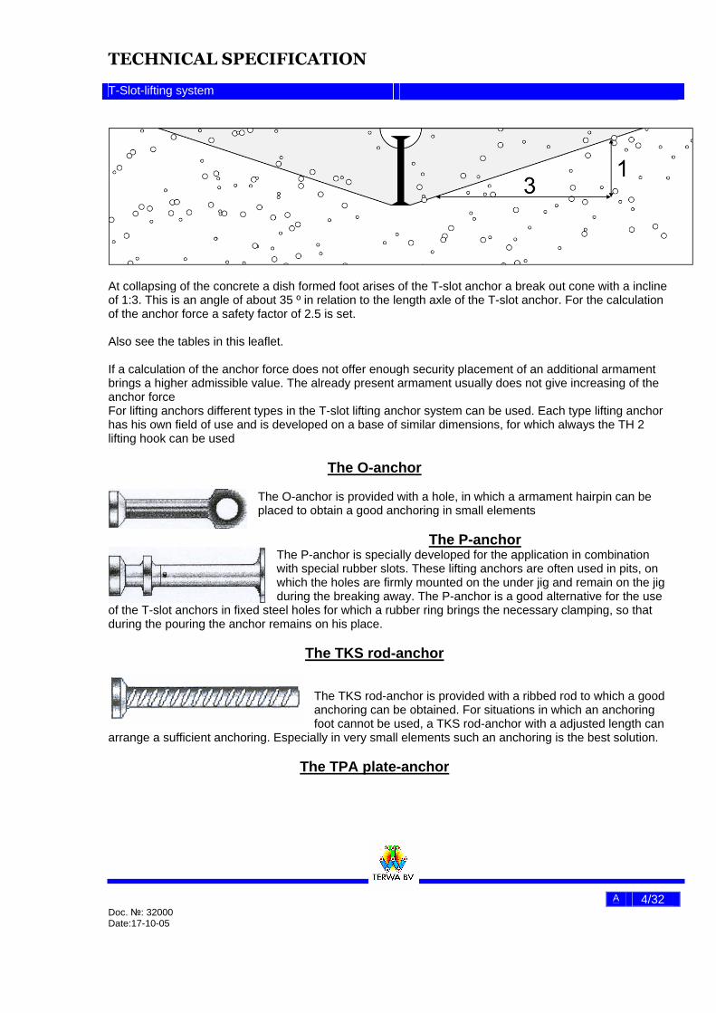
At collapsing of the concrete a dish formed foot arises of the T-slot anchor a break out cone with a incline of 1:3. This is an angle of about 35 º in relation to the length axle of the T-slot anchor. For the calculation of the anchor force a safety factor of 2.5 is set. Also see the tables in this leaflet. If a calculation of the anchor force does not offer enough security placement of an additional armament brings a higher admissible value. The already present armament usually does not give increasing of the anchor force For lifting anchors different types in the T-slot lifting anchor system can be used. Each type lifting anchor has his own field of use and is developed on a base of similar dimensions, for which always the TH 2 lifting hook can be used
The O-anchor The O-anchor is provided with a hole, in which a armament hairpin can be placed to obtain a good anchoring in small elements
The P-anchor The P-anchor is specially developed for the application in combination with special rubber slots. These lifting anchors are often used in pits, on which the holes are firmly mounted on the under jig and remain on the jig during the breaking away. The P-anchor is a good alternative for the use
of the T-slot anchors in fixed steel holes for which a rubber ring brings the necessary clamping, so that during the pouring the anchor remains on his place.
The TKS rod-anchor The TKS rod-anchor is provided with a ribbed rod to which a good anchoring can be obtained. For situations in which an anchoring foot cannot be used, a TKS rod-anchor with a adjusted length can
arrange a sufficient anchoring. Especially in very small elements such an anchoring is the best solution.
The TPA plate-anchor
TECHNICAL SPECIFICATION
T-Slot-lifting system
A 5/32 Doc. №: 32000 Date:17-10-05
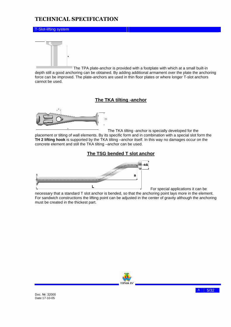
The TPA plate-anchor is provided with a footplate with which at a small built-in depth still a good anchoring can be obtained. By adding additional armament over the plate the anchoring force can be improved. The plate-anchors are used in thin floor plates or where longer T-slot anchors cannot be used.
The TKA tilting -anchor
The TKA tilting -anchor is specially developed for the placement or tilting of wall elements. By its specific form and in combination with a special slot form the TH 2 lifting hook is supported by the TKA tilting –anchor itself. In this way no damages occur on the concrete element and still the TKA tilting –anchor can be used.
The TSG bended T slot anchor
For special applications it can be necessary that a standard T slot anchor is bended, so that the anchoring point lays more in the element. For sandwich constructions the lifting point can be adjusted in the center of gravity although the anchoring must be created in the thickest part.
TECHNICAL SPECIFICATION
T-Slot-lifting system
A 6/32 Doc. №: 32000 Date:17-10-05
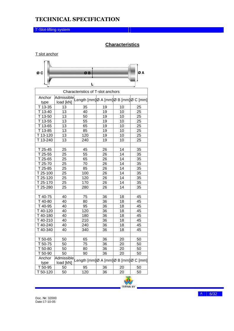
Characteristics T slot anchor
Characteristics of T-slot anchors
Anchor type
Admissible load [kN]
Length [mm] Ø A [mm] Ø B [mm] Ø C [mm]
T 13-35 13 35 19 10 25 T 13-40 13 40 19 10 25 T 13-50 13 50 19 10 25 T 13-55 13 55 19 10 25 T 13-65 13 65 19 10 25 T 13-85 13 85 19 10 25
T 13-120 13 120 19 10 25 T 13-240 13 240 19 10 25
T 25-45 25 45 26 14 35 T 25-55 25 55 26 14 35 T 25-65 25 65 26 14 35 T 25-70 25 70 26 14 35 T 25-85 25 85 26 14 35
T 25-100 25 100 26 14 35 T 25-120 25 120 26 14 35 T 25-170 25 170 26 14 35 T 25-280 25 280 26 14 35
T 40-75 40 75 36 18 45 T 40-80 40 80 36 18 45 T 40-95 40 95 36 18 45
T 40-120 40 120 36 18 45 T 40-180 40 180 36 18 45 T 40-210 40 210 36 18 45 T 40-240 40 240 36 18 45 T 40-340 40 340 36 18 45
T 50-65 50 65 36 20 50 T 50-75 50 75 36 20 50 T 50-80 50 80 36 20 50 T 50-90 50 90 36 20 50 Anchor
type Admissible load [kN] Length [mm] Ø A [mm] Ø B [mm] Ø C [mm]
T 50-95 50 95 36 20 50 T 50-120 50 120 36 20 50

TECHNICAL SPECIFICATION
T-Slot-lifting system
A 7/32 Doc. №: 32000 Date:17-10-05
T 50-160 50 160 36 20 50
T 50-180 50 180 36 20 50 T 50-210 50 210 36 20 50 T 50-240 50 240 36 20 50 T 50-340 50 340 36 20 50
T 75-85 75 85 47 24 60 T 75-95 75 95 47 24 60
T 75-120 75 120 47 24 60 T 75-150 75 150 47 24 60 T 75-160 75 160 47 24 60 T 75-200 75 200 47 24 60 T 75-300 75 300 47 24 60 T 75-540 75 540 47 24 60
T 100-100. 100 100 47 28 60 T 100-110 100 110 47 28 60 T 100-115 100 115 47 28 60 T 100-120 100 120 47 28 60 T 100-135 100 135 47 28 60 T 100-150 100 150 47 28 60 T 100-170 100 170 47 28 60 T 100-250 100 250 47 28 60 T 100-340 100 340 47 28 60 T 100-650 100 650 47 28 60 T 100-680 100 680 47 28 60
T 150-140 150 140 70 39 80 T 150-150 150 150 70 39 80 T 150-165 150 165 70 39 80 T 150-200 150 200 70 39 80 T 150-210 150 210 70 39 80 T 150-300 150 300 70 39 80 T 150-400 150 400 70 39 80 T 150-840 150 840 70 39 80
T 200-165 200 165 70 39 98 T 200-250 200 250 70 39 98 T 200-340 200 340 70 39 98 T 200-500 200 500 70 39 98
TECHNICAL SPECIFICATION
T-Slot-lifting system
A 8/32 Doc. №: 32000 Date:17-10-05
Anchor type
Admissible
load [kN]
Length [mm]
Ø A [mm] Ø B [mm] Ø C [mm]
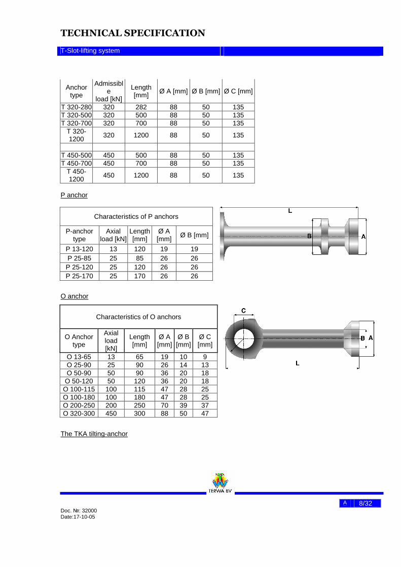
T 320-280 320 282 88 50 135 T 320-500 320 500 88 50 135 T 320-700 320 700 88 50 135
T 320-1200 320 1200 88 50 135
T 450-500 450 500 88 50 135 T 450-700 450 700 88 50 135
T 450-1200 450 1200 88 50 135
P anchor
O anchor
The TKA tilting-anchor
Characteristics of P anchors
P-anchor type
Axial load [kN]
Length [mm]
Ø A [mm] Ø B [mm]
P 13-120 13 120 19 19 P 25-85 25 85 26 26 P 25-120 25 120 26 26 P 25-170 25 170 26 26
Characteristics of O anchors
O Anchor type
Axial load [kN]
Length [mm]
Ø A [mm]
Ø B [mm]
Ø C [mm]
O 13-65 13 65 19 10 9 O 25-90 25 90 26 14 13 O 50-90 50 90 36 20 18
O 50-120 50 120 36 20 18 O 100-115 100 115 47 28 25 O 100-180 100 180 47 28 25 O 200-250 200 250 70 39 37 O 320-300 450 300 88 50 47
TECHNICAL SPECIFICATION
T-Slot-lifting system
A 9/32 Doc. №: 32000 Date:17-10-05
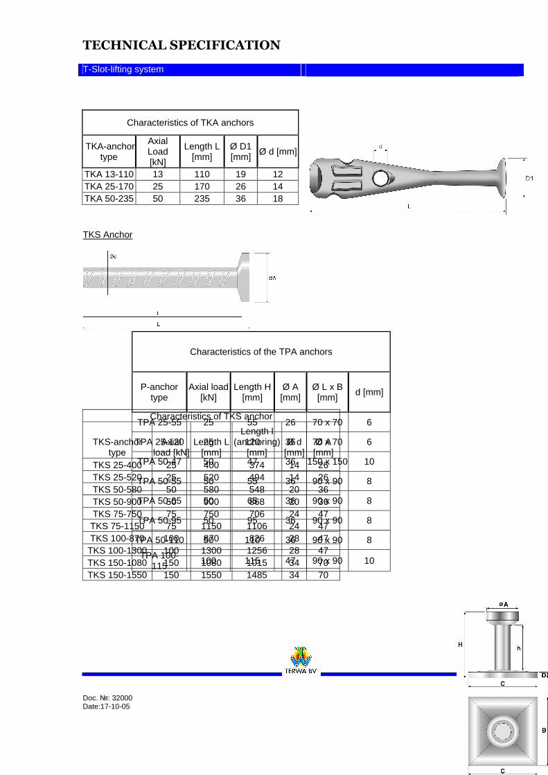
TKS Anchor
Characteristics of TKA anchors
TKA-anchor type
Axial Load [kN]
Length L [mm]
Ø D1 [mm] Ø d [mm]
TKA 13-110 13 110 19 12 TKA 25-170 25 170 26 14 TKA 50-235 50 235 36 18
Characteristics of TKS anchor
TKS-anchor type
Axial load [kN]
Length L [mm]
Length l (anchoring)
[mm] Ø d
[mm] Ø A [mm]
TKS 25-400 25 400 374 14 26 TKS 25-520 25 520 494 14 26 TKS 50-580 50 580 548 20 36 TKS 50-900 50 900 868 20 36 TKS 75-750 75 750 706 24 47 TKS 75-1150 75 1150 1106 24 47 TKS 100-870 100 870 826 28 47
TKS 100-1300 100 1300 1256 28 47 TKS 150-1080 150 1080 1015 34 70 TKS 150-1550 150 1550 1485 34 70
Characteristics of the TPA anchors
P-anchor type
Axial load [kN]
Length H [mm]
Ø A [mm]
Ø L x B [mm]
d [mm]
TPA 25-55 25 55 26 70 x 70 6
TPA 25-120 25 120 36 70 x 70 6
TPA 50-47 50 47 36 150 x 150 10
TPA 50-55 50 55 36 90 x 90 8
TPA 50-65 50 65 36 90 x 90 8
TPA 50-95 50 95 36 90 x 90 8
TPA 50-110 50 110 36 90 x 90 8
TPA 100-115 100 115 47 90 x 90 10
TECHNICAL SPECIFICATION
T-Slot-lifting system
A 10/32 Doc. №: 32000 Date:17-10-05
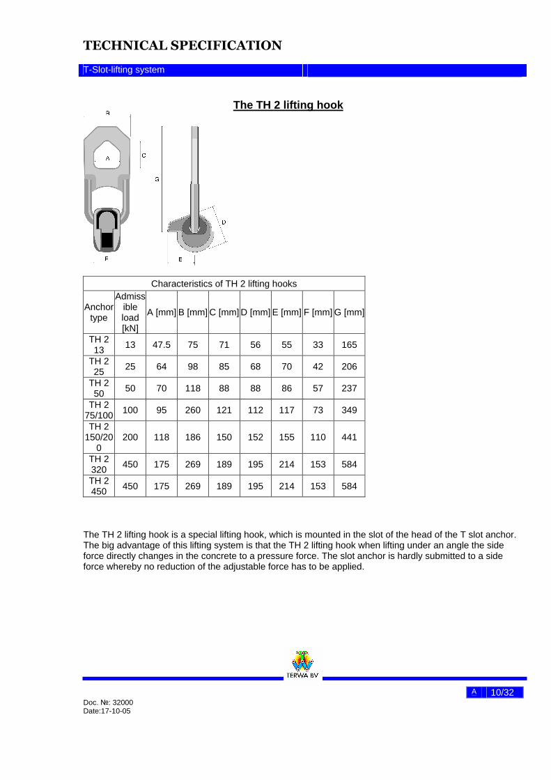
The TH 2 lifting hook
Characteristics of TH 2 lifting hooks
Anchor type
Admissible load [kN]
A [mm] B [mm] C [mm] D [mm] E [mm] F [mm] G [mm]
TH 2 13 13 47.5 75 71 56 55 33 165
TH 2 25 25 64 98 85 68 70 42 206
TH 2 50 50 70 118 88 88 86 57 237
TH 2 75/100 100 95 260 121 112 117 73 349
TH 2 150/20
0 200 118 186 150 152 155 110 441
TH 2 320 450 175 269 189 195 214 153 584
TH 2 450 450 175 269 189 195 214 153 584
The TH 2 lifting hook is a special lifting hook, which is mounted in the slot of the head of the T slot anchor. The big advantage of this lifting system is that the TH 2 lifting hook when lifting under an angle the side force directly changes in the concrete to a pressure force. The slot anchor is hardly submitted to a side force whereby no reduction of the adjustable force has to be applied.

TECHNICAL SPECIFICATION
T-Slot-lifting system
A 11/32 Doc. №: 32000 Date:17-10-05
Lifting under an angle
When lifting under a angle there has to be taken into account the enlarging of the forces in the lifting cable. The force has to be multiplied with the factor, which is mentioned in the above table. When the angle in relation to the concrete is smaller than 30º the forces in the lifting cable will increase in such a way that it will beneath. In that case another solution has to be found f.i. longer lifting cables. The use of the TH 2 lifting hook is simple and the coupling is a quick simple action. If the lifting hook is coupled to the T slot anchor, lifting is possible. Advisable is to bring the lip of the TH 2 lifting hook in between the lifting cable and the concrete. In that case when loading under a angle the lip will be pushed to the concrete. For tilting in the air there has to be taken into account that the lip of the TH 2 lifting hook will be pushed to the concrete and not that the possibility arises that the ball of the lifting hook can turn out of the socket in the concrete. The TH 2 lifting hook is standard with an individual certificate according to European norms with which the user for 4 years only visually checks has to be taken for detecting any abnormality and checking if the wear measurements are not over or under passed.
Lifting angles
Angle α to concrete [º] 90 75 60 45 30
Addition factor in force in the
lifting part 1 1.04 1.16 1.43 2

TECHNICAL SPECIFICATION
T-Slot-lifting system
A 12/32 Doc. №: 32000 Date:17-10-05
Checking measurements by reasons of wear to the lifting hook has to be done regularly (at least once a year according to this table IN CASE OF EXCEEDING: DISAPPROVAL
H
M
The TH 2 lifting hook has a safety factor for breaking of 5 After testing of the TH 2 lifting hook with a sample load of 3 times the admissible load, a separate number is punched on the lifting hooks, which is the same as the numbers on the test certificates. The original certificate belongs to the buyer. Copies are saved in the test institute and at Terwa BV. After 4 years the TH 2 lifting hooks have to be tested again independently of the use.
Wear measurements
TYPE H –
MAXIMUM [mm]
M –MINIMUM
[mm]
TH 2 13 13 8
TH 2 25 18 10
TH 2 50 25 13
TH 2 75/100 34 17
TH 2 150/200
45 23
TH 2 320/450 57 33

TECHNICAL SPECIFICATION
T-Slot-lifting system
A 13/32 Doc. №: 32000 Date:17-10-05
Attachment of the lifting anchors in the concrete To couple the TH 2 lifting hook to the T slot anchor there must be a socket in the concrete. This socket has a ball form en can be as well as well a half ball and a small ball slot. Different aiding kits are available to realize this socket. For a half ball socket the TH 2lifting hook can be attached in any direction and eventually can turn during lifting in the socket till the lifting hook has arrived its good position. Most usable is the ball socket RB The ball socket RB
The ball socket RB has a ball form and can be mounted to the formwork with the aid of the attached IP inlay plate, which is applied with thread. The inlay plate can be mounted to the formwork with for instance a bolt. The inlay plate as well as the fixing bolt is available with speed thread In the case that the T slot anchor has to be placed in the concrete at a point with lack of space a smaller socket can be used, the SRB-socket. This socket is just big enough to mount the TH 2 lifting hook to the head of the T slot anchor, but the lifting hook cannot turn any more to all directions The SRB-socket
Beside in rubber the sockets can also be delivered in steel and hard plastic. The SB socket also is deliverable with and without magnets
Dimensions of the ball socket RB
Type R[mm] A[mm] B [mm] Ø C[mm] RB 13 kN 30 8 5 10 RB 25 kN 37 12 7 14 RB 50 kN 47 12 10 20
RB 75/100 kN 59 12 10 28 RB 150/200 kN 80 12 10 39 RB 320450 kN 102 16 15 50
Dimensions of the ball socket SRB
Type R[mm] M[mm] N [mm] C[mm] SRB 25 kN 37 43 52 14 SRB 50 kN 47 58 69 20
SRB 75/100 kN 59 74 85 28 SRB 150/200 kN 80 112 124 39 SRB 320/450 kN ON DEMAND
TECHNICAL SPECIFICATION
T-Slot-lifting system
A 14/32 Doc. №: 32000 Date:17-10-05
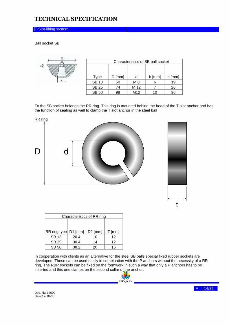
Ball socket SB
Characteristics of SB ball socket
Type D [mm] a b [mm] c [mm] SB 13 50 M 8 6 19 SB 25 74 M 12 7 26 SB 50 98 M12 10 36
To the SB socket belongs the RR ring. This ring is mounted behind the head of the T slot anchor and has the function of sealing as well to clamp the T slot anchor in the steel ball RR ring
Characteristics of RR ring
RR ring type D1 [mm] D2 [mm] T [mm] SB 13 20.4 10 12 SB 25 30.4 14 12 SB 50 38.2 20 16
In cooperation with clients as an alternative for the steel SB balls special fixed rubber sockets are developed. These can be used easily in combination with the P anchors without the necessity of a RR ring. The RBP sockets can be fixed on the formwork in such a way that only a P anchors has to be inserted and this one clamps on the second collar of the anchor.
TECHNICAL SPECIFICATION
T-Slot-lifting system
A 15/32 Doc. №: 32000 Date:17-10-05
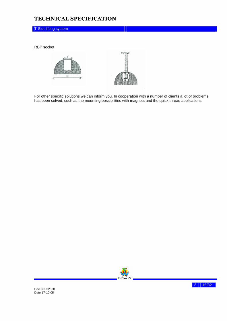
RBP socket
For other specific solutions we can inform you. In cooperation with a number of clients a lot of problems has been solved, such as the mounting possibilities with magnets and the quick thread applications
TECHNICAL SPECIFICATION
T-Slot-lifting system
A 16/32 Doc. №: 32000 Date:17-10-05
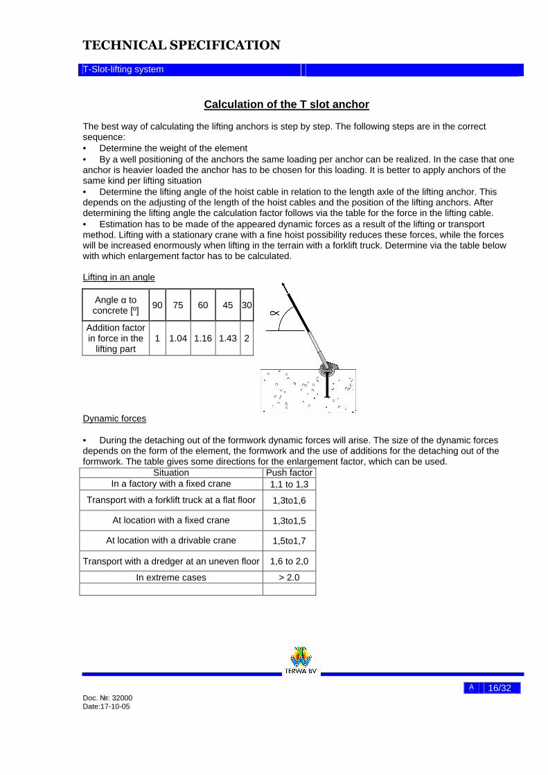
Calculation of the T slot anchor The best way of calculating the lifting anchors is step by step. The following steps are in the correct sequence: • Determine the weight of the element • By a well positioning of the anchors the same loading per anchor can be realized. In the case that one anchor is heavier loaded the anchor has to be chosen for this loading. It is better to apply anchors of the same kind per lifting situation • Determine the lifting angle of the hoist cable in relation to the length axle of the lifting anchor. This depends on the adjusting of the length of the hoist cables and the position of the lifting anchors. After determining the lifting angle the calculation factor follows via the table for the force in the lifting cable. • Estimation has to be made of the appeared dynamic forces as a result of the lifting or transport method. Lifting with a stationary crane with a fine hoist possibility reduces these forces, while the forces will be increased enormously when lifting in the terrain with a forklift truck. Determine via the table below with which enlargement factor has to be calculated. Lifting in an angle
Dynamic forces
• During the detaching out of the formwork dynamic forces will arise. The size of the dynamic forces depends on the form of the element, the formwork and the use of additions for the detaching out of the formwork. The table gives some directions for the enlargement factor, which can be used.
Angle α to concrete [º]
90 75 60 45 30
Addition factor in force in the
lifting part 1 1.04 1.16 1.43 2
Situation Push factor In a factory with a fixed crane 1,1 to 1,3
Transport with a forklift truck at a flat floor 1,3to1,6
At location with a fixed crane 1,3to1,5
At location with a drivable crane 1,5to1,7
Transport with a dredger at an uneven floor 1,6 to 2,0
In extreme cases > 2.0
TECHNICAL SPECIFICATION
T-Slot-lifting system
A 17/32 Doc. №: 32000 Date:17-10-05
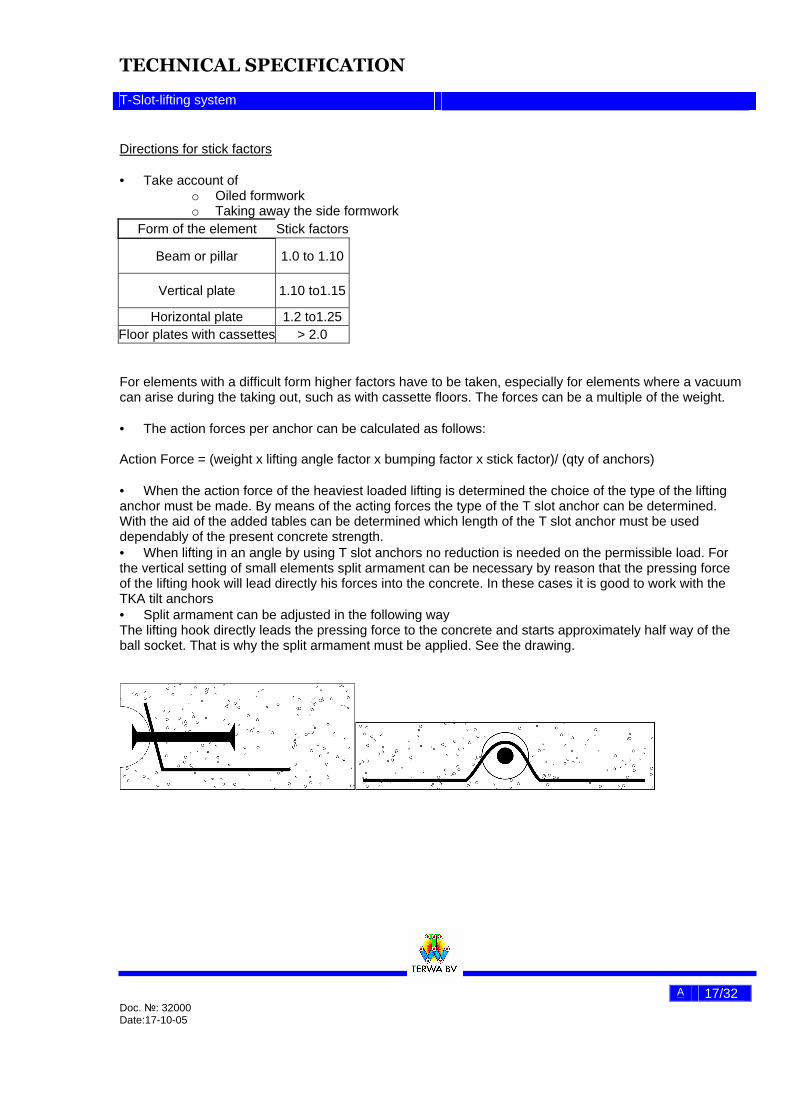
Directions for stick factors • Take account of
o Oiled formwork o Taking away the side formwork
Form of the element Stick factors
Beam or pillar 1.0 to 1.10
Vertical plate 1.10 to1.15
Horizontal plate 1.2 to1.25 Floor plates with cassettes > 2.0
For elements with a difficult form higher factors have to be taken, especially for elements where a vacuum can arise during the taking out, such as with cassette floors. The forces can be a multiple of the weight. • The action forces per anchor can be calculated as follows: Action Force = (weight x lifting angle factor x bumping factor x stick factor)/ (qty of anchors) • When the action force of the heaviest loaded lifting is determined the choice of the type of the lifting anchor must be made. By means of the acting forces the type of the T slot anchor can be determined. With the aid of the added tables can be determined which length of the T slot anchor must be used dependably of the present concrete strength. • When lifting in an angle by using T slot anchors no reduction is needed on the permissible load. For the vertical setting of small elements split armament can be necessary by reason that the pressing force of the lifting hook will lead directly his forces into the concrete. In these cases it is good to work with the TKA tilt anchors • Split armament can be adjusted in the following way The lifting hook directly leads the pressing force to the concrete and starts approximately half way of the ball socket. That is why the split armament must be applied. See the drawing.

TECHNICAL SPECIFICATION
T-Slot-lifting system
A 18/32 Doc. №: 32000 Date:17-10-05
Anchoring of T slot anchors
If the loading type of the T slot anchors has been chosen the length of the anchor has to be determined. Dependably of the form of the element en the strength of the concrete at the first loading a T slot anchor has to be chosen that realizes a larger anchoring force, than is calculated as the acting force. The admissible anchoring force is calculated with a safety factor of 2,5. The foot of the T slot anchor obtains the anchoring. At collapsing of the concrete a dish formed foot arises of the T-slot anchor a break out cone with an incline of 1:3.that is why that relatively small anchoring lengths will do. In this leaflet tables are added, to which in practice most of the situations can be filled in. It is also possible to make an exact calculation of the present situation. On request special tables can be made which fulfils the practical situation at the prefab mill or at the building place. If it is possible to divide elements in the below groups then the following rule of thump can be used. In case of inexperience with the T slot anchor system additional information is always obtainable at Terwa. Type of element: • Beams: T slot anchors with the standard length per loading type can be used. • Horizontal plates T slot anchors with a smaller length than standard can be used • Vertical plates T slot anchors with a larger length than standard must be used Overview of T slot anchor length
Loading class [kN]
Standard type T-slot
anchor
Often used
shortened T-slot
anchor
Often used lengthened
T-slot anchor
13 T 13-120 T 13-65 T 13-240 25 T 25-170 T 25-85 T 25-280 50 T 50-240 T 50-120 T 50-340 75 T 75-300 T 75-150 T 75-540
100 T 100-340 T 100-170 T 100-680 150 T 150-400 T 150-210 T 150-840 200 T 200-500 T 200-340 T 200-500 320 T 320-700 T 320-500 T 320-1200 450 T 450-700 T 450-500 T 450-1200
All deliverable types of T slot anchors are mentioned in the product documentation and the pricelist and can be delivered in bright, thermic zinced or stainless steel
TECHNICAL SPECIFICATION
T-Slot-lifting system
A 19/32 Doc. №: 32000 Date:17-10-05
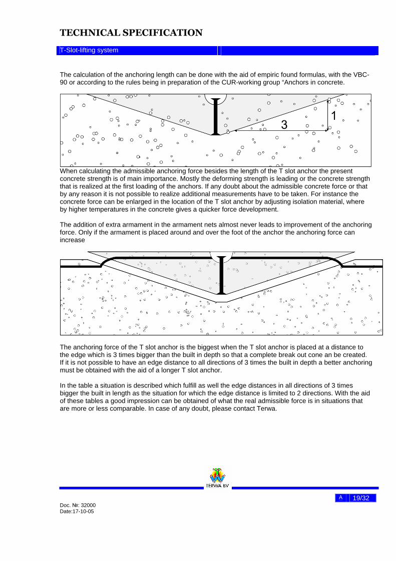
The calculation of the anchoring length can be done with the aid of empiric found formulas, with the VBC-90 or according to the rules being in preparation of the CUR-working group “Anchors in concrete.
When calculating the admissible anchoring force besides the length of the T slot anchor the present concrete strength is of main importance. Mostly the deforming strength is leading or the concrete strength that is realized at the first loading of the anchors. If any doubt about the admissible concrete force or that by any reason it is not possible to realize additional measurements have to be taken. For instance the concrete force can be enlarged in the location of the T slot anchor by adjusting isolation material, where by higher temperatures in the concrete gives a quicker force development. The addition of extra armament in the armament nets almost never leads to improvement of the anchoring force. Only if the armament is placed around and over the foot of the anchor the anchoring force can increase
The anchoring force of the T slot anchor is the biggest when the T slot anchor is placed at a distance to the edge which is 3 times bigger than the built in depth so that a complete break out cone an be created. If it is not possible to have an edge distance to all directions of 3 times the built in depth a better anchoring must be obtained with the aid of a longer T slot anchor. In the table a situation is described which fulfill as well the edge distances in all directions of 3 times bigger the built in length as the situation for which the edge distance is limited to 2 directions. With the aid of these tables a good impression can be obtained of what the real admissible force is in situations that are more or less comparable. In case of any doubt, please contact Terwa.
TECHNICAL SPECIFICATION
T-Slot-lifting system
A 20/32 Doc. №: 32000 Date:17-10-05
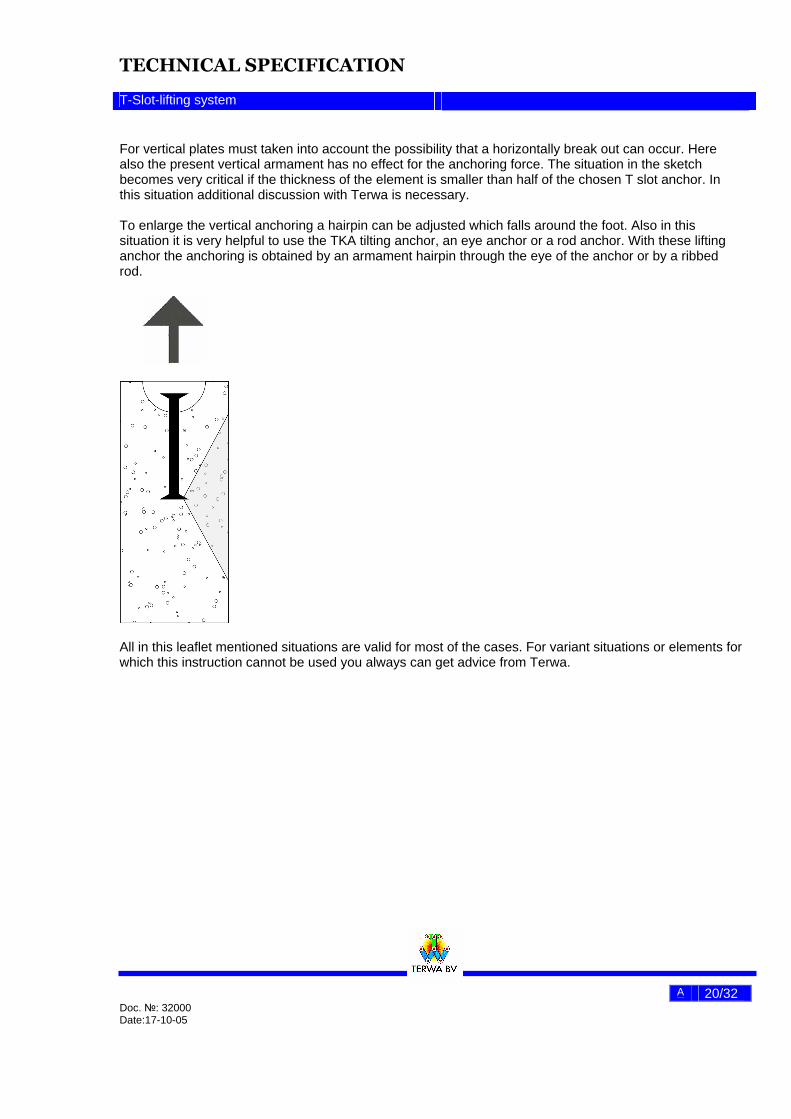
For vertical plates must taken into account the possibility that a horizontally break out can occur. Here also the present vertical armament has no effect for the anchoring force. The situation in the sketch becomes very critical if the thickness of the element is smaller than half of the chosen T slot anchor. In this situation additional discussion with Terwa is necessary. To enlarge the vertical anchoring a hairpin can be adjusted which falls around the foot. Also in this situation it is very helpful to use the TKA tilting anchor, an eye anchor or a rod anchor. With these lifting anchor the anchoring is obtained by an armament hairpin through the eye of the anchor or by a ribbed rod.
All in this leaflet mentioned situations are valid for most of the cases. For variant situations or elements for which this instruction cannot be used you always can get advice from Terwa.

TECHNICAL SPECIFICATION
T-Slot-lifting system
A 21/32 Doc. №: 32000 Date:17-10-05
Calculation example 1
Floor element: Dimensions 5.00 x 2.00 x0.20 m³ 4 T-slot anchors Concrete strength class B45 Strength at deboxing 20 N/mm²
Situation at the works: The element will be taken out of the box with a portal crane. There is worked with an equator to prevent that the angle to the concrete becomes smaller than 75 º. The to be used lifting anchor factor will be 1.04. Also will be taken into account: A push factor of 1.3 and a Stick factor of 1.2 Situation at the building area: The element will be built up with the aid of a turning crane. There is worked with 2 hooks equator to prevent that the angle to the concrete becomes smaller than 60 º. The to be used lifting anchor factor will be 1.16. Also will be taken into account: A push factor of 1.3 Determination of the weight: G= 5.00 x 2.0 x 0.2 (m³ x 25 kN/m³) = 50 kN Determination of the arisen force per anchor: At the works:
50 x 1.04 x1.3 x1.2 Force per anchor: F = ____________________ = 20.3 kN → normative 4
at the building area
50 x 1.16 x1.3 Force per anchor: F = _________________ = 18.9 kN 4
The situation at the works during deboxing is for the choice of the loading class normative T -Slot anchor: T -25 kN Determination of the length of the T –Slot anchor"
TECHNICAL SPECIFICATION
T-Slot-lifting system
A 22/32 Doc. №: 32000 Date:17-10-05
According to the Table the T –Slot anchor Type T -25-120 already will do at a concrete strength of 20
N/mm².
According to rule of thumb for a Floor element normally a T –Slot anchor in shortened implementation can be used. In this case also a T -25-120 or a T -25-170 can be chosen. Terwa B.V. can execute for you a special calculation, for which the exact anchoring length can be calculated Final conclusion. The floor element can be hoisted with 4 T –Slot anchor Type T -25-120 in black, zincked or in stainless
steel.
Choosen positions: Length direction: ca. 1/5 of the length = 1,00 m from the edge Transverse direction: ca. 30% of the width = 0,50 m from the edge
TECHNICAL SPECIFICATION
T-Slot-lifting system
A 23/32 Doc. №: 32000 Date:17-10-05
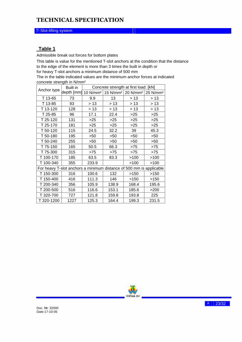
Table 1
Admissible break out forces for bottom plates
This table is value for the mentioned T-slot anchors at the condition that the distance to the edge of the element is more than 3 times the built in depth or for heavy T-slot anchors a minimum distance of 500 mm The in the table indicated values are the minimum anchor forces at indicated concrete strength in N/mm²
Concrete strength at first load: [kN] Anchor type Built in
depth [mm] 10 N/mm² 15 N/mm² 20 N/mm² 25 N/mm² T 13-65 73 9.9 13 > 13 > 13 T 13-85 93 > 13 > 13 > 13 > 13 T 13-120 128 > 13 > 13 > 13 > 13 T 25-85 96 17.1 22.4 >25 >25 T 25-120 131 >25 >25 >25 >25 T 25-170 181 >25 >25 >25 >25 T 50-120 115 24.5 32.2 39 45.3 T 50-180 195 >50 >50 >50 >50 T 50-240 255 >50 >50 >50 >50 T 75-150 165 50.5 66.3 >75 >75 T 75-300 315 >75 >75 >75 >75
T 100-170 185 63.5 83.3 >100 >100 T 100-340 355 233.9 >100 >100
For heavy T-slot anchors a minimum distance of 500 mm is applicable T 150-300 316 100.6 132 >150 >150 T 150-400 416 111.3 146 >150 >150 T 200-340 356 105.9 138.9 168.4 195.6 T 200-500 516 116.6 153.1 185.6 >200 T 320-700 727 121.8 159.8 193.8 225 T 320-1200 1227 125.3 164.4 199.3 231.5
TECHNICAL SPECIFICATION
T-Slot-lifting system
A 24/32 Doc. №: 32000 Date:17-10-05
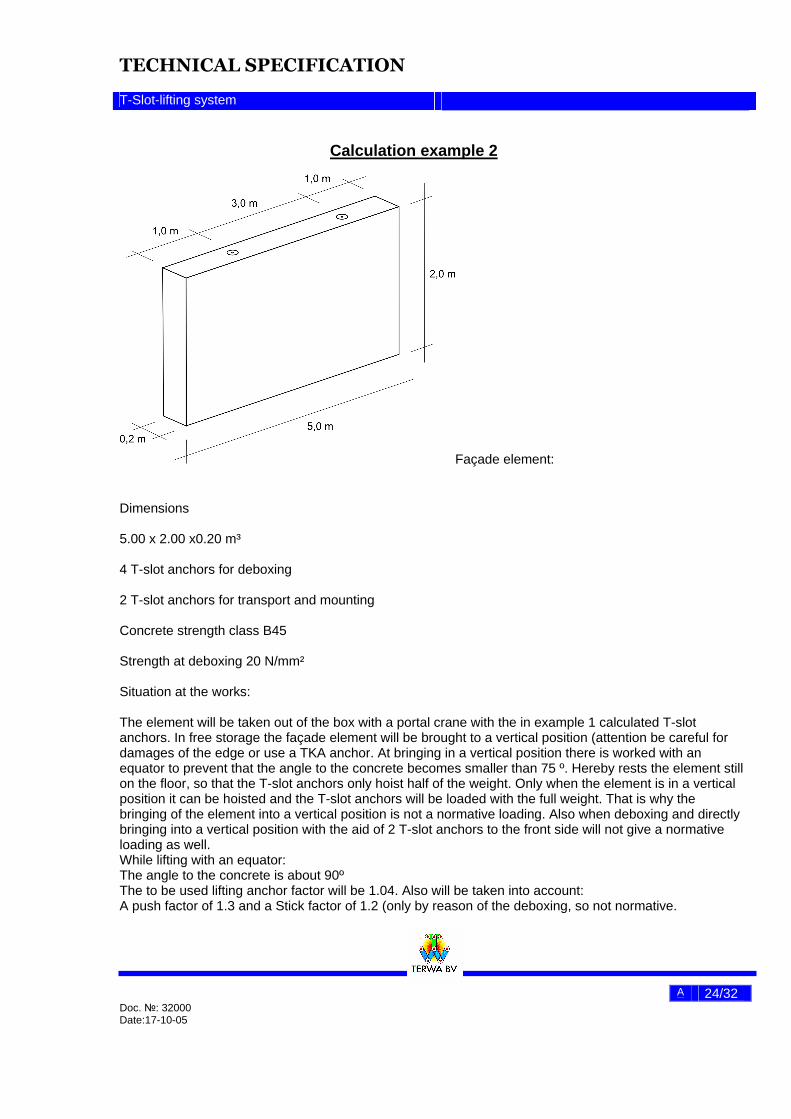
Calculation example 2
Façade element: Dimensions 5.00 x 2.00 x0.20 m³ 4 T-slot anchors for deboxing 2 T-slot anchors for transport and mounting Concrete strength class B45 Strength at deboxing 20 N/mm² Situation at the works: The element will be taken out of the box with a portal crane with the in example 1 calculated T-slot anchors. In free storage the façade element will be brought to a vertical position (attention be careful for damages of the edge or use a TKA anchor. At bringing in a vertical position there is worked with an equator to prevent that the angle to the concrete becomes smaller than 75 º. Hereby rests the element still on the floor, so that the T-slot anchors only hoist half of the weight. Only when the element is in a vertical position it can be hoisted and the T-slot anchors will be loaded with the full weight. That is why the bringing of the element into a vertical position is not a normative loading. Also when deboxing and directly bringing into a vertical position with the aid of 2 T-slot anchors to the front side will not give a normative loading as well. While lifting with an equator: The angle to the concrete is about 90º The to be used lifting anchor factor will be 1.04. Also will be taken into account: A push factor of 1.3 and a Stick factor of 1.2 (only by reason of the deboxing, so not normative.

TECHNICAL SPECIFICATION
T-Slot-lifting system
A 25/32 Doc. №: 32000 Date:17-10-05
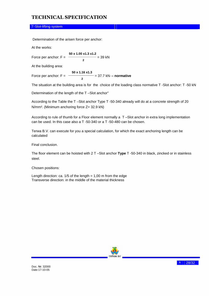
Situation at the building area: The element will be built up with the aid of a turning crane. There is worked with 2 hooks equator to prevent that the angle to the concrete becomes about 60 º. The to be used lifting anchor factor will be 1.16. Also will be taken into account: A push factor of 1.3 Determination of the weight: G= 5.00 x 2.0 x 0.2 (m³ x 25 kN/m³) = 50 kN Determination of the arisen force per anchor: At the works:
50 x 1.00 x 1.3 x 1.2 Force per anchor: F = ________________________ = 39 kN 2
At the building area
50 x 1.16 x1.3 Force per anchor: F = ____________________ = 37.7 kN 2
The situation at the building area is for the choice of the loading class normative T -Slot anchor: T -50 kN Determination of the length of the T –Slot anchor" According to the Table the T –Slot anchor Type T -50-340 already will do at a concrete strength of 20
N/mm². (Minimum anchoring force Z= 32.9 kN)
According to rule of thumb for a facade element normally a T –Slot anchor in extra long implementation can be used. In this case also a T -50-340 or a T -50-480 can be chosen. Terwa B.V. can execute for you a special calculation, for which the exact anchoring length can be calculated Final conclusion.
The facade element can be hoisted with 2 T –Slot anchor Type T -50-340 in black, zincked or in stainless
steel. Chosen positions: Length direction: ca. 1/5 of the length = 1,00 m from the edge Transverse direction: in the middle of the material thickness
Table 2 Admissible break out forces for façade plates & beams

TECHNICAL SPECIFICATION
T-Slot-lifting system
A 26/32 Doc. №: 32000 Date:17-10-05
This table is value for the mentioned T-slot anchors at the condition that the distance to the edge of the element is more than 3 times the built in depth and the anchor is built in the middle of the material thickness a minimum distance of 500 mm The in the table indicated values are the minimum anchor forces at indicated concrete strength in N/mm²
Concrete strength at first load: [kN]
Anchor type Built in depth [mm]
Wall thickness
[mm] 10 N/mm² 15 N/mm² 20 N/mm² 25 N/mm² 30 N/mm²
T 13-120 128 80 5 6.5 7.9 9.2 10.3 T 13-120 128 120 7.4 9.7 11.8 > 13 > 13 T 13-240 248 80 9.6 12.6 > 13 > 13 > 13 T 13-240 248 120 > 13 > 13 > 13 > 13 > 13 T 25-170 181 100 8.8 11.5 13.9 16.2 18.3 T 25-170 181 140 12.2 16 19.5 22.6 >25 T 25-280 291 100 14.1 18.5 22.5 >25 >25 T 25-280 291 140 19.7 >25 >25 >25 >25 T 50-240 255 120 14.8 19.5 23.6 27.4 31 T 50-240 255 160 19.7 25.9 31.4 36.5 41.2 T 50-340 355 120 20.7 27.1 32.9 38.2 43.2 T 50-340 355 160 27.5 36.1 43.8 >50 >50 T 50-480 495 120 28.8 37.8 45.9 >50 >50 T 50-480 495 160 38.4 >50 >50 >50 >50 T 75-300 315 160 24.4 32 38.8 45.1 51 T 75-300 315 200 30.5 40 48.5 56.3 63.6 T 75-540 555 160 43.1 56.6 68.6 >75 >75 T 75-540 555 200 53.8 70.7 >75 >75 >75 T 100-340 355 200 34.4 45.1 54.7 63.5 71.8 T 100-340 355 250 42.9 56.3 68.2 79.2 89.5 T 100-680 695 200 67.5 88.5 >100 >100 >100 T 100-680 695 250 84.3 >100 >100 >100 >100 T 150-400 416 250 50.3 66 80.1 93 105.1
T 150-400 416 300 60.3 79.1 98.9 111.4 125.8 T 200-500 516 300 74.9 98.3 119.2 138.4 156.4 T 200-500 516 350 87.3 114.5 138.9 161.3 182.2 T 320-700 727 400 140.8 184.7 224 260.1 293.9
Calculation example 3

TECHNICAL SPECIFICATION
T-Slot-lifting system
A 27/32 Doc. №: 32000 Date:17-10-05
Façade element: Determination of the maximum weight Starting points: For the transportation 2 T-slot anchors are put in the front side For deboxing use 4 T-slot anchors or bringing the element in vertical position with the 2 T-slot anchors in the front side(attention be careful for damages of the edge) Strength at deboxing 15 N/mm² Situation at the works: In free storage the façade element will be brought to a vertical position (attention be careful for damages of the edge or use a TKA anchor At bringing in a vertical position there is worked with an equator to prevent that the angle to the concrete becomes smaller than 75 º. The angle to the concrete is about 90º The to be used lifting anchor factor will be 1.00. Also will be taken into account: Push factor = 1.3 Determination of the arisen force per anchor
G max. x 1.00 x1.3 Arisen force: F = ______________________ 2 anchors
In table 3 an overview of the maximum weights has been given for the façade elements when using 2 T-slot anchors of the in the first column mentioned types. For all the cases in between or divergent positions Terwa B.V. can make a special calculation or make a special table for your works.
TECHNICAL SPECIFICATION
T-Slot-lifting system
A 28/32 Doc. №: 32000 Date:17-10-05
Determination of the arisen force per anchor: At the works:
50 x 1.00 x1.3 x1.2 Force per anchor: F = ______________________ = 39 kN 2
At the building area:
50 x 1.16 x1.3 Force per anchor: F = ____________________ = 37.7 kN→ normative 2
The situation at the building area is for the choice of the loading class normative T -Slot anchor: T -50 kN Determination of the length of the T –Slot anchor" According to the Table the T –Slot anchor Type T -50-340 already will do at a concrete strength of 20
N/mm². (Minimum anchoring force Z= 32.9 kN)
According to rule of thumb for a Floor element normally a T –Slot anchor in extra long implementation can be used. In this case also a T -50-340 or a T -50-480 can be chosen. Terwa B.V. can execute for you a special calculation, for which the exact anchoring length can be calculated Final conclusion. The floor element can be hoisted with 2 T –Slot anchor Type T -50-340 in black, zincked or in stainless
steel.
Chosen positions: Length direction: ca. 1/5 of the length = 1,00 m from the edge Transverse direction: in the middle of the material thickness
TECHNICAL SPECIFICATION
T-Slot-lifting system
A 29/32 Doc. №: 32000 Date:17-10-05
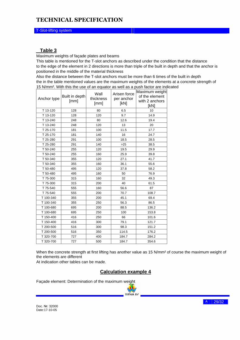
Table 3
Maximum weights of façade plates and beams This table is mentioned for the T-slot anchors as described under the condition that the distance to the edge of the element in 2 directions is more than triple of the built in depth and that the anchor is positioned in the middle of the material thickness Also the distance between the T-slot anchors must be more than 6 times of the built in depth the in the table mentioned values are the maximum weights of the elements at a concrete strength of 15 N/mm². With this the use of an equator as well as a push factor are indicated
Anchor type Built in depth [mm]
Wall thickness
[mm]
Arisen force per anchor
[kN]
Maximum weight of the element with 2 anchors
[kN] T 13-120 128 80 6.5 10 T 13-120 128 120 9.7 14.9 T 13-240 248 80 12.6 19.4 T 13-240 248 120 13 20 T 25-170 181 100 11.5 17.7 T 25-170 181 140 16 24.7 T 25-280 291 100 18.5 28.5 T 25-280 291 140 >25 38.5 T 50-240 255 120 19.5 29.9 T 50-240 255 160 25.9 39.8 T 50-340 355 120 27.1 41.7 T 50-340 355 160 36.1 55.6 T 50-480 495 120 37.8 58.2 T 50-480 495 160 50 76.9 T 75-300 315 160 32 49.3 T 75-300 315 200 40 61.5 T 75-540 555 160 56.6 87 T 75-540 555 200 70.7 108.7
T 100-340 355 200 45.1 69.4 T 100-340 355 250 56.3 86.5 T 100-680 695 200 88.5 136.2 T 100-680 695 250 100 153.8 T 150-400 416 250 66 101.6 T 150-400 416 300 79.1 121.7 T 200-500 516 300 98.3 151.2 T 200-500 516 350 114.5 176.2 T 320-700 727 400 184.7 284.2 T 320-700 727 500 184.7 354.6
When the concrete strength at first lifting has another value as 15 N/mm² of course the maximum weight of the elements are different At indication other tables can be made.
Calculation example 4 Façade element: Determination of the maximum weight

TECHNICAL SPECIFICATION
T-Slot-lifting system
A 30/32 Doc. №: 32000 Date:17-10-05
Starting point For the transportation 2 T-slot anchors are put in the front side For deboxing use 4 T-slot anchors or bringing the element in vertical position with the 2 T-slot anchors in the front side(attention be careful for damages of the edge) Strength at deboxing 35 N/mm²
Situation at the works and at the building area: In free storage the façade element will be brought to a vertical position (attention be careful for damages of the edge or use a K2 kip anchor. At bringing in a vertical position there is worked with a spring is used with a top angle smaller than 60 º. The to be used lifting anchor factor will be 1.16. Also will be taken into account: Push factor = 1.3 For deboxing other T-slot anchors are used. That is why no stick forces have to be taken into account. Also when the bringing in vertical position from out the box is used then also the stick forces are not normative, because of only the halve of the forces have to be taken into account Determination of the arisen force per anchor
Gmax. x 1.16 x 1.3 Arisen force: F = _____________________ 2 anchors
In table 4 an overview of the maximum weights has been given for the façade elements when using 2 T-slot anchors of the in the first column mentioned types. For all the cases in between or divergent positions Terwa B.V. can make a special calculation or make a special table for your works.
Table 4 Maximum weights of façade plates and beams This table is mentioned for the t-slot anchors as described under the condition that the distance to the edge of the element in 2 directions is more than triple of the built in depth and that the anchor is positioned in the middle of the material thickness Also the distance between the T-slot anchors must be more than 6 times of the built in depth The in the table mentioned values are the maximum weights of the elements at a concrete strength of

TECHNICAL SPECIFICATION
T-Slot-lifting system
A 31/32 Doc. №: 32000 Date:17-10-05
35 N/mm². At bringing in a vertical position there is worked with a spring is used with a top angle smaller than 60 º.
Anchor type Built in depth [mm]
Wall thickness [mm]
Arisen force per anchor
[kN]
Maximum weight of the
element with 2 anchors [kN]
T 13-120 128 80 11.5 15.2 T 13-120 128 120 13 17.2 T 13-240 248 80 13 17.2 T 13-240 248 120 13 17.2 T 25-170 181 100 20.3 26.9 T 25-170 181 140 25 33.2 T 25-280 291 100 25 33.2 T 25-280 291 140 25 33.2 T 50-240 255 120 34.3 45.5 T 50-240 255 160 45.7 60.6 T 50-340 355 120 47.8 63.5 T 50-340 355 160 50 66.3 T 50-480 495 120 50 66.3 T 50-480 495 160 50 66.3 T 75-300 315 160 56.5 75 T 75-300 315 200 70.5 93.5 T 75-540 555 160 75 99.5 T 75-540 555 200 75 99.5
T 100-340 355 200 79.6 105.5 T 100-340 355 250 99.2 131.6 T 100-680 695 200 100 132.6 T 100-680 695 250 100 154.5 T 150-400 416 250 116.5 185 T 150-400 416 300 139.5 230 T 200-500 516 300 173.4 265.3 T 200-500 516 350 200 424.4 T 320-700 727 400 450 424.4 T 320-700 727 500 450 354.6
When the concrete strength at first lifting has another value as 35 N/mm² of course the maximum weight of the elements are different At indication other tables can be made.
Threat analysis
Threat Risk Counter measurements Mechanical threat by finger injuries at screwing in hoisting noose
S C: One and two hand operation is possible; at least: trained personnel at works and at the building area
Mechanical threat by finger injuries at screwing in hoisting noose in the transport anchor
S UI: suggestion for put down the elements on blocks
Overload of the transport anchor by wrong hoisting direction
S
UI: load values have taken into account wrong hoisting directions
Overload of the transport anchor caused by not using a transverse or equator
S
UI: load values have taken a 3 times safety factor for such mistakes
TECHNICAL SPECIFICATION
T-Slot-lifting system
A 32/32 Doc. №: 32000 Date:17-10-05
S= small UI=user instruction
====================