the tenth chesapeake sailing yacht …vm2330.sgvps.net/~syrftest/images/library/20160122191817.pdfa...
TRANSCRIPT

-THE TENTH CHESAPEAKE SAILING YACHT SYMPOSIUM
GYRADIUS MEASUREMENTS OF OLYMPIC CLASS DINGHIES AND KEEL BOATS Peter F. Hinrichsen, University of Montreal, Montreal, Quebec, Canada
ABSTRACT
Modern construction techniques allow dinghy hulls to be built well under the minimum weight specified by the class rules. This has lead to a trend, notably in the Olympic dinghy classes, towards hulls with light ends, especially light bows. A number of classes, of which the Finn was the first, have therefore introduced means of measuring the fore and aft weight distribution. Measurements of the pitch and yaw gyradii of Flying Dutchman hulls made at the 1976, 1984 and 1988 Olympic regattas, as well as data for a number of other classes are presented. The various methods used for gyradius measurement are compared, with special emphasis on their precision, accuracy, worldwide reproducibility and the systematic corrections required. Calculations of the contribution of each of the components, including the crew, to the total moment of inertia are presented for Flying Dutchmen.
NOMENCLATURE
a Distance from the horizontal pivot axis to the CG.
a c Distance from the trailer axle to the CG of the boat plus trailer, in the bounce test.
b
BcG B(t)
d
D
Distance from the trailer axle to the trailer CG, in the bounce test. Distance between the axes in a Lamboley test. Athwartships position of the CG. Bow displacement during the in the water test. Half the spacing between the wires of a bifilar suspension. Distance from the axis of rotation to the spring attachment point in the bounce and Snipe tests.
1
g
HcG
H(t)
le
ly
ky
I LcG
M Mc
Mt
The gravitational acceleration, 9.81 m/s2. Vertical position of the CG, above the deckline. Heave motion during the in the water test. Moment of Inertia of the boat about the trailer axle in the bounce test. Moment of Inertia of the boat plus trailer in the bounce test. Moment of Inertia of the empty trailer in the bounce test. Moment of Inertia of the total boat including the crew. Moment of Inertia about the pitch axis through the CG. Moment of Inertia about the yaw axis through the CG. Gyradius about the pitch axis through a point on the keel rubbing strake vertically below the CG. Gyradius about the pitch axis through the CG. Gyradius about the yaw axis through the CG. Length of bifilar suspension wires. Horizontal position of the CG forward of the transom. Length from the bow sensor to the applied force W, for the in the water test.
Length between the bow and stern sensors for the in the water test. Length from the center of pitch to the applied force W, for the in the water test. Horizontal distance from the standard mass m to the axis, for the inclineswing test. Mass of the hull. Mass of boat plus trailer in the bounce test. Mass of the empty trailer in the bounce test.

S Spring constant of the spring used for
the Bounce and Snipe tests.
S(t) Stern displacement during the in the
water test. Tc Period of oscillation of boat plus trailer
in the bounce test. T 1 Period of oscillation of the empty
trailer in the bounce test.
Ts Period of sway oscillation for the
bifilar suspension. T )' Period of yaw oscillation for the bifilar
suspension. W Force applied at the bow for the in the
water test.
a Angular acceleration.
a( 0) Pitch angular acceleration at t
the in the water test.
0 Angular displacement
0 for
0(t) Pitch motion during the in the water
test. r Torque.
r g Gravitational torque.
rs Spring torque.
WEIGHT DISTRIBUTION MEASUREMENT
Modern construction methods allow the
hulls of racing dinghies to be built
significantly under the minimum weight
specified in the class rules and the question
then is where to put the extra weight. It
would be beneficial for the average sailor if it
was used to make a stronger and longer
lasting boat, however builders are
concentrating the weight and moving it aft,
because many top sailors are convinced that
such hulls give them a speed advantage. Past
experience has shown that clever builders can
usually circumvent scantling rules. In contrast determining the weight distribution
with a swing test controls the gyradius or
moment of inertia, i.e. those charncteristics of
the boat which affect it's speed, while leaving the construction free. However, swing tests
require the accurate timing of some type of
angular oscillation and this is both time
consuming and requires carefully controlled
measuring conditions if the required precision
and reproducibility are to be achieved.
THE EFFECT ON PERFORMANCE
It is not the intent of this paper to
discuss the ways in which the distribution of
weight can affect boats peed. However, many
sailors are, rightly or wrongly, convinced that
light ends are beneficial so a short discussion
is in order. For a boat sailing on ideally flat
2
water in a constant wind so that it does not
roll, pitch or yaw, the concentration of the
weight would have no effect on the boat's
motion, or on its speed. However, except in
very light winds we do not sail in this way,
and the boat oscillates about an average
attitude as it progresses. Only the two
rotational oscillations, pitch and yaw, are
directly affected by the fore and aft
distribution of the weight. When a boat pitches the buoyancy
tends to counteract the motion so as to bring
the boat back towards an even keel, however,
the boat overshoots and then oscillates back
and forth with a natural pitching frequency
[l]. If waves are encountered at the natural
pitching frequency of the boat then each
wave adds to the pitching motion until it
builds up and reduces the boat's forward
speed. The weight distribution affects the
period of "natural pitching" and hence the
synchronism with the wave encounter
frequency which is necessary for the pitching
to build up. The effect of the fore and aft weight
distribution on the feel of a sailing dinghy
may also be due, at least in part, to it's
influence on the steering response. When
sailing in waves it is well known that the
helmsman does not steer a straight course.
The motion can be thought of as a constant
average motion in the direction of the course,
plus a yaw oscillation. This yawing oscillation
is not like the pitching oscillation, for which
the changing buoyancy provides a natural
restoring torque, but is purposely introduced
by the helmsman's use of the rudder and of
sail trim. When the boat is steered off course,
there is no natural tendency for it to be
restored to the original course, the helmsman
again has to use the rudder. The fore and aft
weight distribution of the boat directly affects
the boat's response to these rudder actions.
A boat with heavy ends will respond more
slowly, or will require more violent rudder
action for it to respond as rapidly as a boat
with light ends.
CENTER OF GRAVITY, CG
The average position of the weight
determines the position of the Center of
Gravity, i.e. the CG of the boat, which in turn
affects the average attitude and stability of
the boat when sailing. Many dinghy sailors
believe that a light bow is more important
than a low gyradius, i.e. that the CG should be
as far aft as possible. Fortunately the fore
and aft position of the CG can be easily

measured and is a natural part of any of the swing tests to be discussed. It makes little sense to regulate the gyradius without also specifying the fore and aft position of the CG. The vertical position of the CG which affects the stability is measured as part of the Lamboley and Incline-swing tests and can also be determined by balancing the hull on a gunwale.
WEIGHT DISTRIBUTION MEASUREMENT METHODS
To determine the longitudinal distribution of the weight in a nondestructive manner, one must measure the moment of inertia about either the horizontal pitch or the vertical yaw axis, and this requires a dynamical measurement. The moment of inertia about a given axis can be expressed as I = Mk 2. where M is the mass of the hull and k is the gyradius. I and k depend on both the orientation and position of the axis of rotation, i.e. the roll moment of inertia is very different from that for pitch or yaw. It is customary to quote gyradius about an axis through the CG as this is the minimum value for rotation about a given direction and the gyradius about any parallel axis can be easily computed from it.
The moment of inertia cannot be measured by any static method as it only enters the rotational statement of Newtons second law, namely r = Ia where r is the
applied torque and a is the resulting angular acceleration. This relation is the basis of all measurements of moments of inertia and hence of gyradii. The "in the water method" of measurement proposed by Watt Webb [2] uses this equation directly. All the other methods employ a restoring torque I (e)
which is ideally proportional to the angular displacement e from the equilibrium position and produces oscillatory motion. A measurement of the frequency or period of the oscillation together with the functional dependence of the torque on angular displacement give the moment of inertia. For the "Lamboley test", the "Incline-swing test" and the "Bifilar suspension" the weight and the geometry of the suspension determine the torque while for the methods used by the Snipe, Comet and Lightning classes a standard spring at a fixed lever arm provides the restoring torque.
It is of great importance that the chosen method has the highest precision possible. The weight distribution is characterized by
3
the gyradius k which is a length, and the sailor's natural expectation is that one can measure it with the same ±I mm precision with which other dimensions are measured! Such precision cannot presently be achieved and it is the object of this paper to examine the reproducibility and precision of the methods currently used.
THE LAMBOLEY TEST
Ideally the period of small amplitude oscillation Tl of a rigid body of gyradius k and with its CG a distance a below a horizontal axis from which it is freely suspended is
( I )
Unfortunately this period depends on the unknown distance a as well as the gyradius k which one wants to measure. This difficulty can be overcome if two periods of oscillation, about two axes which are a known
distance b apart, are measured. The period about the lower axis is
(2)
The unknown distance a from the upper axis to the center of mass is then
a =
Leo
b(gT~ + 4rt2b)
g(T~ - Ty)+ 8rt2b (3)
Photocell Timer
Fig. 1 For a Lamboley test the hull is suspended from a horizontal knife edge and the two periods of oscillation T 1 and T 2 about two axes a distance b = 200 mm apart are measured. The pitch gyradius k p and the vertical and horizontal positions of the CG, a and L can then be calculated.

and the gyradius is given by
(4)
For a hull suspended from a horizontal athwartships axis, see Fig. 1, the pitch gyradius kp about the center of mass can therefore be determined from measurements of the spacing b, and the two periods T J, and T 2 . In 1970 Gilbert Lamboley [3] introduced this method, with b = 200 mm, and the Furn class has successfully used the "Lamboley Test" for the past 20 years. The Europa class has also adopted this test and many other classes including the Flying Dutchman and 470 have considered the adoption of the Lamboley Test, and made detailed studies of the weight distribution of hulls using this technique [4].
The practical usefulness of the Lamboley Test has been well established, however it has a number of disadvantages. The most obvious is that two periods have to be measured, and this is very time consuming when many boats have to be checked and rechecked. Photocell timing and portable computers speed up the procedure but have the effect of adding an air of
"FD Amplitude 0 VS Time" 0
'O 00 "' ... E
0 <:P 40
G> 'O .= 20
a. E ct 1 0
5 0 100 200 300 400 500 600
Time sec
Fig. 2 The decay of the amplitude of pitch oscillation of an FD in a Lamboley test. The initial curvature of this "log plot" indicates the presence of nonlinear damping and the absence of any downward curvature shows that pivot friction is negligible. The data has been fit with a function representing linear and quadratic damping.
4
incomprehensibility to the results. Finally it can be seen from equations (3) and (4) that the gyradius depends on the difference between the squares of the two periods of oscillation, and this limits the precision with which the gyradius can be determined.
The effects of Damping on Precision
The simple theory above does not take into account pivot friction or air damping, and for modern light dinghy hulls even small drafts can affect the period of oscillation. Water in the hull, loose fittings which can flop about, knife edges and/or photocells which are not very rigidly supported can all limit the precision achievable. The presence of even a few hundred grams of free running water in a 125 kg hull cause the amplitude to decrease rapidly and nonuniformly and plays havoc with the period. In comparison the bifilar test is probably much less sensitive to the presence of water, but no detailed observations have yet been made. Thus for precision measurements the hulls must be absolutely dry, which is not always possible at a regatta!
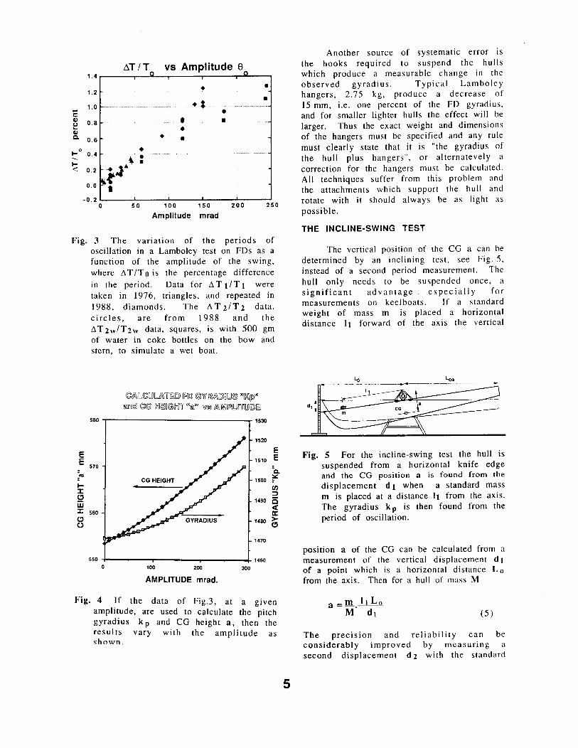
Pivot friction, linear and quadratic air damping, can all be studied by observing the decrease of the amplitude with time, see for example Fig. 2. Pivot friction would cause this data to curve downwards and there is no evidence for this, thus suggesting that friction was negligible. Furthermore, theoretically pivot friction does not affect the period of oscillation [5]. The effect of linear air damping on the period is much smaller than the scatter of the data, and is in any case constant for all hulls of a given class. The quadratic air damping (the presence of which is clearly shown by the fact that the graph in Fig. 2 is not a straight line) however causes the period of oscillation to depend somewhat on the amplitude (6]. The observed variation .of the period with amplitude, see ~ig. 3_, 1s not completely accounted for by this effect. If, for a given hull, the periods T 1 and T 2 are measured using the same amplitude 0 and the pitch gyradius k p and CG height a are calculated then as shown in Fig. 4, the calculated 'values vary quite significantly with the amplitude used for the measurement:. The use of small amplitudes reduces this systematic error but at the expense of maki~g the measurement more sensitive to dratts and thus increasing the random error. The choice of an optimum amplitude is therefore a compromise which may be different for each class.
~T /T vs Amplitude e 1 .4
• • 1 .2
• •• • 1 .0
E • Cl> 0.8 • • u ... • Cl> Q.
0.6 • • 1-0 • 0.4 • I- ~ • <l 0.2 • J ..
0.0 -r • -0.2 0 50 100 150 200 250
Amplitude mrad
Fig. 3 The variation of the periods of oscillation in a Lamboley test on FDs as a function of the amplitude of the swing,
where ~T/Tois the percentage difference
in the period. Data for ~ T 1/T1 were taken in 1976, triangles, and repeated in
1988, diamonds. The ~ T 2/T 2 data, circles, are from 1988 and the
~T2wlT2w data, squares, is with 500 gm of water in coke bottles on the bow and stern, to simulate a wet boat.
E E
570
;ca I-:c <.:> iii :c 560 <.:> (.)
0
©A\ll,©l!JJ~'iJ~[Q) [F[QJ @\Yl~A\[Q)~l!JJ® "OC(p)"" m@ ©C!:ll IXl~~@IXJ'if ""@" w© A\[l)J]~[Llflrl!JJIQJ~
100 200 300
AMPLITUDE mrad.
1520
E 1s10 E
"c. 1500 ~
(/) :::>
1490 cs ~ a: > 1480 <.:>
1470
Fig. 4 If the data of Fig.3, at a given amplitude, are used to calculate the pitch gyradius k p and CG height a, then the results vary with the amplitude as shown.
5
Another source of systematic error 1s the hooks required to suspend the hulls which produce a measurable change in the observed gyradius. Typical Lamboley hangers, 2.75 kg, produce a decrease of 15 mm, i.e. one percent of the FD gyradius, and for smaller lighter hulls the effect will be larger. Thus the exact weight and dimensions of the hangers must be specified and any rule
must clearly state that it is "the gyradius of the hull plus hangers", or alternatevely a correction for the hangers must be calculated. All techniques suffer from this problem and the attachments which support the hull and rotate with it should always be as light as possible.
THE INCLINE-SWING TEST
The vertical position of the CG a can be determined by an inclining test, see Fig. 5, instead of a second period measurement. The hull only needs to be suspended once, a significant advantage especially for measurements on keelboats. If a standard weight of mass m is placed a horizontal distance 11 forward of the axis the vertical
Fig. 5 For the incline-swing test the hull is suspended from a horizontal knife edge and the CG position a is found from the
displacement d 1 when a standard mass m is placed at a distance I 1 from the axis. The gyradi us k p is then found from the period of oscillation.
position a of the CG can be calculated from a measurement of the vertical displacement d t of a point which is a horizontal distance L 0
from the axis. Then for a hull of mass M
(5)
The precision and reliability can be considerably improved by measuring a second displacement d 2 with the standard

mass a nominally equal distance 12 towards the stern, then
a = m {Lo [-1_1 + --1LJ- ao) M 2 d1 d2
where for completeness a small correction for the average distance a 0 of the standard mass below the pivot is included (the system should be designed to make a 0 zero). The value of a together with a single period of oscillation T, about the same axis, w he n substituted into equation (1) give the pitch gyradius k P. This method is used by the Dragon class, and was used for tests on some Tornado hulls at the Olympic regatta in Pusan. The Royal New Zealand Yacht Squadron tested the Stewart 34s previously used for the Squadron Cup match races with this technique. Further advantages are that a static deflection can be easily averaged, and the presence of water in the hull causes the deflection d to change continuously. The only minor drawback is that the mass of the hull M must be measured accurately, but this is in any case part of the measurement procedure.
For the measurements on Tornado hulls the major sources of uncertainty in the CG position a (± 1 mm) were the mass of the hull M (±0.25%) and the deflection d (± 1 mm i.e.
±0.5% with m = 200 gm) leading to an uncertainty in the gyradius of ± 4.2 mm. The period of oscillation could be measured to ± 5 msec which leads to a further uncertainty in the gyradius of ± 1 mm. For similar timing uncertainties using the Lamboley test the results give similar precision, however the Lamboley test results are much more sensitive to timing uncertainties. The use of an electronic level and photocell coupled to a computer, could materially improve the precision and turn around time of this method.
THE BIFILAR SUSPENSION
The bifilar suspension 17, 8] shown in Fig. 6 is an alternative way to generate a torque which is derived from gravity. The hull is suspended symmetrically by two parallel wires of length 1, and spacing 2d. When hanging freely with the hull level the CG is in the plane of the wires, and half way between them. For small angular displacements e, from equilibrium, the two wires become inclined to the vertical, the CG rises by z = d2e2/21, and the period of the
6
resulting simple harmonic motion is
T = 2rtky . IT y d I/ g (7)
Then the yaw gyradius k y is given by
(8)
Thus the gyradius is directly proportional to the measured period Ty. and the constant of proportionality depends only on the geometry of the suspension, which can be chosen so as to make the constant a round number.
Another significant advantage is that the apparatus required can easily be made at home. This method is commonly used on tank test models, has been used on sailboards, lasers, 470s, an International 14 and to measure Flying Dutchman at the '84 and '88 Olympics, and at the 1990 World Championships in Newport (where 75 hulls were measured in three days).
One drawback is that the boat is free to oscillate in a number of ways other than the yaw oscillation which is to be measured, i.e. in sway as a simple pendulum, and in coupled pitch and heave. By timing with a vertical photogate at the bow the effect of heave and pitch on the measured period are eliminated. Releasing the hull while keeping its center under a plumb bob, which is on the center
VERTICAL WIRES LENGTH "["
1 Fig. 6 For the bifilar suspension test the
hull is symmetrically suspended by two vertical wires of length I and spacing 2 d. The period of yaw oscillation then gives the yaw gyradius k y directly.

line of the suspension, reduces the sway to less than 1 % of the yaw amplitude at the bow. However, this modulation is still the major cause of timing uncertainties.
The athwartships bifilar suspension prevents any roll rotation thus the sway period is
(9)
and Ty/Ts= ky/d i.e. the sway oscillation can be made a harmonic of the yaw oscillation by choosing the spacing d to be an integral fraction of ky. The modulation by a harmonic should then not influence the yaw period, as measured from the zero crossing times at the bow. Thus for an athwartships suspension, which facilitates measuring the fore and aft position of the CG, a spacing 2d = ky should be chosen ( d = k y is much larger than the beam, but is the best choice if a fore and aft suspension is used). By averaging measurements of the period over one beat cycle any residual effects of sway can be made negligible.
The crossbar or other support which swings with the hull should be light, and a suspension which uses hooks under the gunwales, the separation of which is controlled by a taught cross wire has proved practical. For a fore and aft suspension such as was used for sailboards a spacing d = k y eliminates any correction for the mass of the hooks. The mass of the suspension wires leads to a negligible correction, however some care must be taken with the end fittings which must not allow the motion of the hull to twist the wires, otherwise the torsional rigidity of the wires adds an unknown torque. The length I and spacing 2d can be measured to ± 1 mm. The residual sway modulation of the period TY• which for the measurements on FDs was ± 7 msec (but much less when averaged) is the limiting factor on the precision of the method. An uncertainty of ± 7 msec in the period corresponds to an uncertainty of ±2 mm in the gyradius. This is significantly better than can be achieved with a Lamboley test. The insensitivity of this test to off center positioning of the CG has been confirmed by measurements on an International 14 and its sensitivity confirmed to be better than ±2 mm by placing up to 5 kg at various positions in the 94 kg hull. Measurements of the decay of the amplitude, similar to those shown in Fig. 2. have been made and show that, as expected, the air damping is less in yaw than in pitch.
7
The beating of the sway and yaw oscillations can be used to measure the gyradius directly. If the hull is released from a position which is displaced in sway but with the hull rotated so that the bow is at its equilibrium pos1t1on it will oscillate in rotation about the bow, which remains stationary, if d = k y. This can be achieved
by adjusting the spacing d. After the system is tuned one just measures d to determine the gyradius ky. without the use of a stop watch! However despite the fact that only one end of one suspension wire need be adjusted (the wires need only be approximately vertical) the tuning takes too much time for this to be a practical technique at regattas. If only a lower limit is to be set for the gyradius then d can be set at this limit, i.e. kymin =d. A practiced measurer can then tell from the combined sway-yaw motion of the suspended hull whether the gyradius is larger or smaller than d. Convincing a competitor that his hull is illegal would however require highly technical explanations!
SPRING OSCILLATOR METHODS
In 1965 Robert Smithers [ 91 developed a method of measuring the moment of inertia of a fully rigged Lightning (without the sails) while it was on its trailer. His aim was to investigate the difference in weight distribution between wooden and fiberglass boats as cheaply as possible. The tongue of the trailer was attached to a calibrated spring, of spring constant S, and by rhythmically pushing the trailer tongue the boat was made to oscillate in pitch about the trailer axle. The measured period of oscillation then gives the moment of inertia le of the boat plus trailer. A separate measurement on the empty trailer gives its moment of inertia It which can then be subtracted to obtain I b i.e. that of the boat alone about the trailer axle. Separate measurements of the distance a of the CG from the axle are required in order to convert the result to the moment of inertia about the CG (or other parallel axes such as that through the center of buoyancy). Various methods such as resting the hull on its gunwale and measuring the balancing force required at the
tip of the mast, or alternatively measuring the trailer tongue weight and its variation with angular displacement, were used to obtain the CG position 19].
The principle of this method is similar to those previously described, however the restoring torque is now supplied by the calibrated spring at a lever arm of D i.e. the
horizontal distance of the hitch from the axle. For this setup in which the axis of rotation is below the CG the weight no longer supplies a restoring torque, thus if it is to be only a small perturbation the variation with angle of the gravitational torque i.e. r g = Mga Sine , must be much smaller than that of the torque due to the spring rs= so2e.
For the CG of the boat plus trailer a distance ac vertically above the axle, i.e. zero tongue weight, the period of oscillation is
( 10)
Which gives the Moment of inertia of the boat plus trailer as
le = T~ (s D2 - M cgac} 471:2 ( 1 I )
A similar expression gives the moment of inertia I 1 of the trailer alone and then the moment of inertia of the boat about the trailer axle is
(12)
By appropriate choice of the spring constant S the second bracket (which in any case gets somewhat smaller if the CG is 1wt vertically
above the axle) can be made· a small correction. For high precision measurements the constants a c and at can be determined as mentioned above.
The precision achieved was about ±I % and clearly differentiated between the wood and the glass boats, see Table II. Estimating the uncertainty in the weight measurements as about ±0.2% the resulting uncertainty in the gyradius is ±0.7% or ± 13 mm which compares favorably with the Lamboley test. For light hulls on heavy trailers the correction for the trailer will add to the uncertainty due to the difference between the squares of the two periods in equation ( 12). The trailer is however unnecessary and in fact can be the cause of added corrections unless both the wheels and the suspension springs are firmly blocked.
In 1971 Ted Wells [IO] eliminated the trailer and simplified this test for use by the Snipe class (I believe the Comet class also use it now) and Dan Williams refined and compared it with the Lamboley test, see
8
~D
TWO CALIBRATED ---------------c.i SP RI NOS I
I
HULL BALLANCED ON HORIZONTAL 318" STEEL ROD BEARING
J
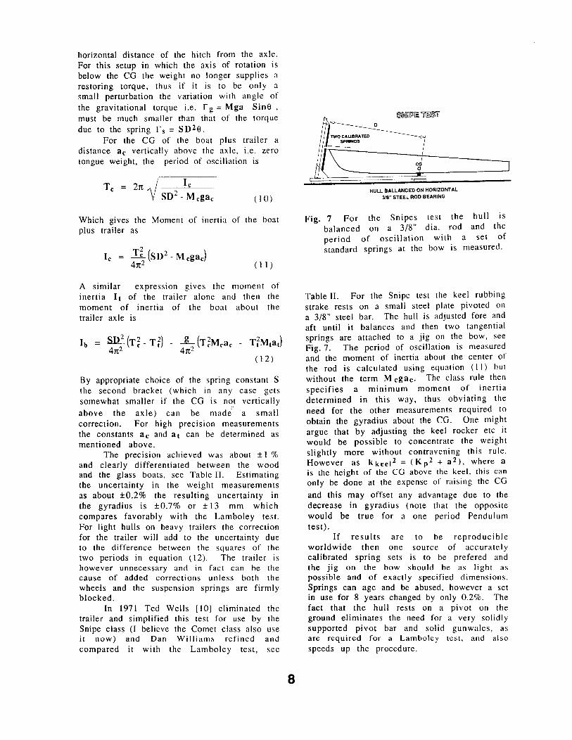
Fig. 7 For the Snipes test the hull is balanced on a 3/8" dia. rod and the period of oscillation with a set of standard springs at the bow is measured.
Table II. For the Snipe test the keel rubbing strake rests on a small steel plate pivoted on a 3/8" steel bar. The hull is adjusted fore and aft until it balances and then two tangential springs are attached to a jig on the bow, see Fig. 7. The period of oscillation is measured and the moment of inertia about the center of the rod is calculated using equation (11) but without the term M cgac. The class rule then specifies a minimum moment of inertia determined in this way, thus obviating the need for the other measurements required to obtain the gyradius about the CG. One might argue that by adjusting the keel rocker etc it would be possible to concentrate the weight slightly more without contravening this rule. However as kkeel2 = (Kp2 + a2), where a is the height of the CG above the keel, this can only be done at the expense of raising the CG
and this may offset any advantage due to the decrease in gyradius (note that the opposite would be true for a one period Pendulum test).
If results are to be reproducible worldwide then one source of accurately calibrated spring sets is to be prefered and the jig on the bow should be as light as possible and of exactly specified dimensions. Springs can age and be abused, however a set in use for 8 years changed by only 0.2%. The fact that the hull rests on a pivot on the ground eliminates the need for a very solidly supported pivot bar and solid gunwales, as are required for a Lamboley test, and also speeds up the procedure.

KEELBOAT TESTS
Performing swing tests on keelboats is clearly a much greater engineering problem as well as being more time consuming. The incline-swing test and the Star class "yaw inertia test" have been used for out of the water measurements. An "in the water test" proposed by Watt Webb [2] is being implemented by Rick McCurdy for possible inclusion in the IMS rule [ 11].
The Dragon class perform an inclineswing test by hoisting the hulls using a jig, attached to the lifting eyes, which allows it to be levelled and to swing in pitch about a swing center which is approximately 570 mm below the deck. They use a standard mass of 10 kg placed 4700 mm forward of the swing center. Some effort is required to measure the 4700 mm with the required accuracy and an error of ±25 mm would lead to an error of ±7 mm in the gyradius. Timing uncertainties of ±20 msec would produce uncertainties of ±6.6 mm in the gyradius. Tests with known added weights at specified positions gave gyradii which reproduced to within ± 0.3% or ±4 mm. The class however have chosen to specify their rule directly in terms of the period of oscillation and the bow deflection in order to avoid calculating the gyradius directly.
In 1987 the Royal New Zealand Yacht Squadron wished to ensure that the wooden and fiberglass Stewart 34s, which they used for the Squadron Challenge Cup match race series, were as equal in performance as possible. They therefore performed inclineswing tests on the boats, see Fig. 8. Tests on one hull which was loaded with extra weights in specified locations indicated that both the CG position a and the gyradius k p could be determined to ± 1 %. Once organized, the tests required only one hour from haulout to relaunch, however the equipment is not easily transportable.
Bill Parks of the Star class pioneered a different approach in 1975. This technique measures the yaw moment of inertia by suspending the hull from a crane with a swivelling hook and attaching a pair of horizontal springs at the bow. The principle is the same as that of the Snipe test except that the rotation is about the yaw axis. The CG is directly below the point of suspension and therefore on the axis of rotation, thus ac in equation (11) is zero. There are however a number of problems with this elegantly simple method. When the hull swings in yaw
9
Fig. 8 A Stewart 34 undergoing a swing test in New Zealand. Photo by Tom Yates.
the pivot must exert a force which is equal and opposite to that due to the springs at the bow, and it is difficult to prevent any lateral motion of the suspension hook. The hook is also not at the same level as the bow springs and thus sway and roll motions will develop. These problems together with friction at the hook and varying torsional rigidity of the suspension led to irreproducible results from site to site. In 1989 the class approached me and I suggested that the hull ~~-su_pported on
a turntable using a vertical truck axle bearing and a light frame which would clamp onto the keel to support the hull. The calibrated springs could be incorporated into the turntable thus making the system self contained. At the present time the Star class has defered any further action until there is clear evidence that a rule is required.
IN THE WATER TESTS
For ocean racing yachts there are obvious advantages to an in the water test which can be performed at the same time as inclining measurements etc. and an "in the water test" was proposed by Watt Webb [2] in 1974. In 1989 the USYRU established a Pitching Moment Project to develop a practical instrument based on this proposal and to collect data on yacht performance in waves, on which a handicapping system for inclusion in the IMS rule could be based. The development of the instrument has been described in detail by Rick McCurdy [11].
An upward force W applied near the bow which displaces the boat in both pitch and heave such that the buoyancy force is reduced by W and the buoyancy torque balances that due to W at a lever arm L p from the center of pitch, see Fig. 9. If the

SNAP SHACKLE f======:::i OAD CELL
Fig. 9 The in the water method uses a string potentiometer B ( t) at the bow and S(t) at the stern to measure the motion following the release from an upward force W near the bow. L p and the initial angular acceleration a(O) can be deduced from the bow and stern motion. The torque and hence the effective moment of inertia can then be calculated.
applied force W is suddenly removed the boat will oscillate with a complex damped pitch-heave motion, however at the instant of release the buoyancy torque responsible for the pitching is equal to the applied torque r = W L p. Measurements of the bow and stern displacements as a function of time, see Fig. 10, then allow both the initial pitch angular acceleration a ( 0) and L p to be determined. Provided that the center of pitch remains fixed relative to the hull, the bow and stern displacements B(t) and S(t) are given by
B(t) = H(t) + (~ + 11>) 0(t) (13)
S(t) = H(t) + (~ + 4>-11>s)9(t) (14)
where 11> is the distance between the bow sensor and the pull, and 11>s is the distance between the bow and stern sensors. Then,
9(t) = B(t) - S(t) (15)
an d 4>s
~ = 4>s ~Im ~ ~W? -11> (l6)
By differentiating 6(t) twice and extrapolating to time zero the initial angular acceleration a (0) can be determined.
10
70
• 0%0 0
60 0
eO 0
c 50 ·•···· 0 0
.-=: ~
U) 40 0 .•.
0 0 c.. • • • • • Bow position
30 -.; 0 Stern position
20 0 2 4 6 8 1 0
Time Sec
Fig. 10 The bow and stern positions of "Seguin" after release of a 400 lb pull at the bow, see fig. 9. A nonlinear least squares fit to this data, in terms of damped oscillator heave and pitch functions plus offset and drift, allows both the initial pitch acceleration ex ( 0) and Lp to be determined.
Unfortunately H ( t) is unknown and to overcome this Watt Webb proposed a second measurement with the pull at the stern. Only the measured spacing between the two pulls, not Lp, is then required. However this complicates the procedure. The heave and pitch oscillations differ in frequency by about a factor of 2.2 so they can be separated, thus allowing Lp to be determined from just a bow pull. In practice the heave has always been found to be negligible. Then
W Lp = cx(O) B(O) - S(O) (17)
In order to allow precise extrapolation to time zero, damped oscillator functions together with offset and drift parameters were used to model the pitch and heave motions as shown in Fig. IO. A nonlinear least squares fitting routine is used to derive the parameters from a simultaneously fit to B(t) and S(t).
An analysis of the results for five different boats suggests that the moment of inertia in the water can be measured with a standard deviation of ±6%, while L p can be determined to ± 1.2%. Currently the main source of uncertainty is due to heave of the boat against the lifting tackle which causes W to vary. An alternative approach is therefore

being developed, namely the pitch stiffness will be precisely measured with an electronic inclinometer and then the moment of inertia determined from the period of oscillation as recorded by the same inclinometer, in a manner similar to the pendulum tests. This technique has the advantages that neither W or L p have to be determined and that the system does not require any external fixed reference point and will th us be self contained.
It should be pointed out that the in the water tests do not measure the same quantity as those performed out of the water. The energy of oscillation of the water in the vicinity of the hull has to be included in the equations of motion and can be represented as an added mass. Typically the results of mass moments of inertia computed from design weights etc. differ from those measured in the water by a factor of about two. However it can be argued that it is the in the water value which is more relevant and should be used for handicapping purposes.
FL YING DUTCHMAN RES UL TS
Fig. 11 shows the close correlation between the yaw and pitch gyradii of the FDs at Pusan in '88, thus demonstrating that either can be used for the control of weight distribution. The data for FD hulls at the '76,
E 1550
E
:: 1500 'C as ... > (!)1450
.c () -0:::1400
•
us 1350 ._~~ .... ~~ ... ~~...i.~~....i.~~.....1
1350 1400 1450 1500 1550 1600
Yaw Gyradii mm
Fig. 11 The pitch gyradii k p are plotted against the yaw gyradii k y for the FDs at the '88 (triangles) and '84 (diamonds) Olympic Regattas . The close correlation indicates that either k p or k y could be used to control weight distribution.
11
1l 1988 I _JJ. .e. lu.l.1. ~el .l.11. I I I I I I I
en 1.35 ...J
1.40 1.45 1.50 1.55 1.60
...I :::> :c
i ~~03s ..... 1--~~:-:-o ....... ~-1.-4s~l ...... u~:~J~.J...__,~m--1.s_s ....... ---1-.e-o'......-..
z i
1976 I ollll11loml ,. Ill D
1.35 1.40 1.45 1.50 1.55 1.60
GYRADIUS meters
Fig. 12 The distributions of the FD gyradii measured in 1976, '84 and '88 are shown. The 1976 and 1988 data are pitch gyradii, while the 1984 data are yaw gyradii. The arrows indicate the average values. The trend towards increased concentration of the weight is clear.
fD CG i-:>OSiTIOl'llJ ~976-88
t ~f
1988
mllllnlm D .. 2.5 2.6 2.7 2.8 2.9 3.0
en ..J
••• ..J 1984 :::>
~I J: - • 0 2.5 2.6 2.7 2.8 2.9 3.0
a: w
• m
ll == 1976
.•• 1IL :::> z
mm 2.5 2.6 2.7 2.8 2.9 3.0
TRANSOM to CG meters
Fig. 13 The distributions of the fore and aft positions L of the FD Centers of Gravity as measured in 1976, '84 and '88 are shown. The arrows indicate the average values.
The decrease of bow weight of modern FDs is demonstrated.

' ' ' ' .. 0.64 0.56 0.58 0.60 0.62
j t ~ ]198; I II
0.56 0.58 0.60 0.62 ..
0.64 a: w al 6 ~ 1976 + ::::> 5 z
4
3
2
0 0.56 0.58 0.60
PIVOT to CG meters
Fig. 14 The distributions of the vertical positions "a" of the FD CGs in 1976, '84 and '88 are shown. The arrows again indicate the average values. The difference between 1976 and 1988 is probably due to the change from wood to fiberglass construction.
'84 and '88 Olympics are compared in Figs. 12, 13 and 14, which s~ow the gyradii, the transom to CG and the p1vo~ to. CG distances respectively. The arrows md1cate
the average values for each year. The conclusion from this data is that the weight is being concentrated, i.e. smaller gyradii, and moved aft. Clearly a major effort is being put into making the bows lighter, but by how much?
Assuming that the hulls are uniformly lightened, i.e. so the gyradius and CG remain the same, and then that the saved weight is all added at one point, allows one to to estimate the amount and location of the saved weight. Comparing the "Average '76" and "Average '88" FDs suggests that about 23 kg has been saved and moved back to within 1.83 M of the transom. In practice the change is more likely due to the empty bows now in favour, but the estimate of 15-20 kg is in agreement with "boatpark wisdom".
12
Total boat Calculations
It is the total boat, i.e. the hull plus equipment and the crew which interacts with the wind and waves, not just the hull. It would be nice if one could measure the moment of inertia of the total boat, and Robert Smithers has done this for a lightning with everything but the sails. I have performed a Lamboley test on an FD with sails etc. but no crew. However such measurements are not practical as they are very sensitive to drafts. Thus one has to resort to calculations and these can be made assuming a perfectly rigid boat provided the mass, CG position and gyradius of each component is known. The position of the CG of the boat LcG forward of the transom is
LcG =
(18)
where the sum is over all the components. Similar formulae give the vertical location H CG below the deckline and the athwartships position BcG of the CG. The total pitch and yaw moments of inertia about the CG are then
Ip = L mi [(Li - LcG)2 +(Hi - HcG) 2 + k~i]
( 19) and
ly = I, IDi [(Li - LcG) 2 +(Bi - BcG) 2 + k~i]
(20)
The results of such a calculation for an FD are given in Table I. Note that when the crew are added the CG changes position thus the crew moments of inertia cannot simply be added to get the total. Provided the rig is tight, and this is realistic for FDs going upwind in waves, the calculation is probably reliable for the complete boat and this was confirmed by measurement. however, despite what some helmsmen may think of their crews, it is not realistic to assume they are rigid bodies! Thus the values for the total boat are only for guidance. Robert Smithers has made measurements with the crew sitting in a Lighting when pitching on it's trailer, both with the rig tight and with it loose and has found significant differences [ 12].
Although the hull is about 80 percent of the weight of the boat it only contributes 50
percent of the pitching moment, the mast
(31 %) mainsail (6.3%) and rudder (6%) also
make significant contributions in pitch. For
yaw the hull (85%) is the dominant
component and only the rudder (9.3%) makes
a significant contribution. The crew and
helmsman, although more than half of the
total weight, add little to the pitching moment
but as the crew on the trapeze is
perpendicular to the boat he adds
substantially to the yaw moment. It is purely
fortuitous that the mast and crew add to the
moments in such a way that the total pitch
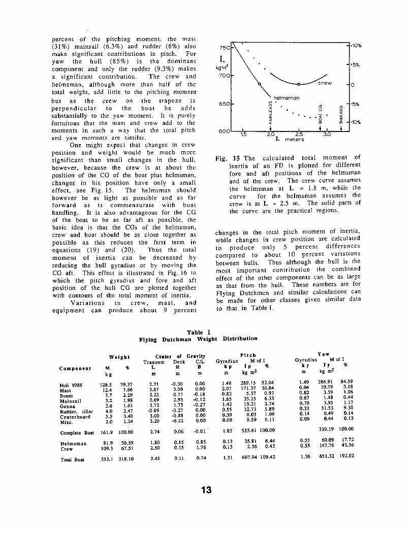
and yaw moments are similar. One might expect that changes in crew
position and weight would be much more
significant than small changes in the hull,
however, because the crew is at about the
position of the CG of the boat plus helmsman,
changes in his position have only a small
effect, see Fig. 15. The helmsman should
however be as light as possible and as far
forward as is commensurate with boat
handling. It is also advantageous for the CG
of the boat to be as far aft as possible, the
basic idea is that the CGs of the helmsman,
crew and boat should be as close together as
possible as this reduces the first term in
equations (19) and (20). Thus the total
moment of inertia can be decreased by
reducing the hull gyradius or by moving the
CG aft. This effect is illustrated in Fig. 16 in
which the pitch gyradius and fore and aft
position of the hull CG are plotted together
with contours of the total moment of inertia.
Variations in crew, mast, and
equipment can produce about 9 percent
Table I
750
IT kgM2
700
650 Vl 0 <i w -' er ~
helmsman
8 ... ~
al
500'--~1~.5;:-~~~2~D;-~~~2~.5~~-L~3.~0~..L..J
L meters
+10%
•5%
0
-5%
-10%
Fig. 15 The calculated total moment of
inertia of an FD is plotted for different
fore and aft positions of the helmsman
and of the crew. The crew curve assumes
the helmsman at L = 1.8 m, while the
curve for the helmsman assumes the
crew is at L = 2.5 m. The solid parts of
the curve are the practical regions.
changes in the total pitch moment of inertia,
while changes in crew position are calculated
to produce only 5 percent differences
compared to about 10 percent variations
between hulls. Thus although the hull is the
most important contribution the combined
effect of the other components can be as large
as that from the hull. These numbers are for
Flying Dutchmen and similar calculations can
be made for other classes given similar data
to that in Table I.
Flying Dutchman Weight Distribution
Weight Center of Gravity Pitch Yaw
Transom Deck C/L Gyradius M of I Gyradius M of I
Component M % L H B kp Ip % ky I y %
kg m m m m kg m2 m kg m2
Hull 1988 128.5 79.37 2.71 -0.30 0.00 1.46 289.15 52.04 1.49 286.91 84.59
Mast 12.4 7.66 3.67 3.00 0.00 2.07 171.37 30.84 0.04 10.79 3.18
Boom 3.7 2.29 2.22 0.77 -0.18 0.82 5.37 0.97 0.82 3.59 1.06
Mainsail 3.2 1.98 2.69 2.93 -0.12 1.65 35.15 6.33 0.67 1.48 0.44
Genoa 2.6 1.61 3.72 1.75 -0.27 1.42 15.21 2.74 0.70 3.95 1.17
Rudder, tiller 4.0 2.47 -0.05 -0.27 0.00 0.55 32.73 5.89 0.33 31.53 9.30
Centerboard 5.5 3.40 3.00 -0.88 0.00 0.39 6.03 1.09 0.14 0.49 0.14
Misc. 2.0 1.24 3.20 -0.22 0.00 0.09 0.59 0.11 0.09 0.44 0.13
Complete Boat 161.9 100.00 2.74 0.06 -0.01 1.85 555.61 100.00 339.19 100.00
Helmsman 81.9 50.59 1.80 0.15 0.85 0.13 35.81 6.44 0.55 60.09 17.72
Crew 109.3 67.51 2.50 0.15 1.76 0.13 2.36 0.42 0.55 147.76 43.56
Total Boat 353.1 218.10 2.45 0.11 0.74 1.31 607.94 109.42 1.36 651.32 192.02
13

1650 680
660 1600
E E 640
1550
620
-g 1500 ... >-~ 600
1450 r:. t) .. -a: 1400
5 8 0 ...... ·····~··
KC : ...._________ ·. ('-US~
13soL-~~-1-~~--1._:_:~~..__-=-~-'-~~--'
2500 2600 2700 2800 2900 3000
Transom to CG mm
Figure 16 The FD pitch gyradius k p is plotted versus the fore and aft position L of the hull CG. Triangles, diamonds and circles are '88, '84 and '76 data respectively. Contours of constant total moment of inertia IT, which assume '88 average values for the other parameters, are also shown.
DATA FOR OTHER CLASSES
The measurements made by a variety of other classes are summarized in Table II. The speed with which a sailboa'rd can be made to respond in both pitch and yaw depends on it's weight distribution. The rig is decoupled from the hull and therefore in this case it does not add to the pitch moment of inertia. Dr Schoop measured a number of sailboards for the IYRU using a bifilar suspension for both the yaw and the pitch gyradius A Lechner board used in Pusan was measured in a similar manner.
The Finn class was the pioneer in the field and an extensive compilation of Finn data exists [13]. The data in Table II is an early sample which is uninfluenced by the introduction of the rule which now limits the gyradius to 1140 < kp < 1300 mm and the CG position to 2000 < LcG < 2250 mm. The 470 class has also collected extensive data at both their 1985 World and 1986 European Championships as well as at the Pusan Olympics. For the latter the IYRU required the 470 gyradius k p > 1180 mm, thus the data for the '86 Europeans is given in Table II.
14
Although not used for the Olympic regatta, the Australians built a pair of extremely light Tornado hulls together with excessively heavy centerboards in order to concentrate the weight, and the boat was reputed to be fast, especially downwind. Leif Smitt and I therefore took the opportunity to make incline-swing tests on these hulls together with hulls from other tune up Tornadoes in Pusan, and the average data is shown in Table II.
The Dragon class now has a weight distribution rule and data from their exploratory tests is given in Table II. to be expected the ratio kp/LOA = much lower than that for the dinghy and compares with ky/LOA = 0.144
As is 0.16 is classes for the
Star class. However it is interesting to note that for the Stewart 34s k p IL 0 A = 0.246 which is similar to that for the dinghies.
CONCLUSION
A number of techniques which have been used to measure the gyradii of boats have been described and the results summarized in the hope that this will allow future work to benefit from this experience.
Opinion on the effect of weight distribution on sailing dinghy characteristics and speed are divided. Many sailors believe it has a significant effect while on the other hand there are reports that under some conditions light ends can be a disadvantage. The statistical evidence from regatta results is inconclusive and subject to interpretation as light ended boats are likely to be sailed by top sailors who leave nothing to chance.
The question could be settled by double blind tests, with matched boats sailed in conditions in which light ends are likely to be significant, but to my knowledge no such tests have been made. The data being collected for the IMS project will provide information on the effect of pitching on keelboat performance and similar data for dinghies would be of great interest, but much harder to obtain. In the mean time improvements in the gyradius measurement techniques will at least improve that aspect of the data.
I would like to thank Cle Jeltes, all those sailors who have cooperated in these measurements, the class measurers who have sent me their data and especially my wife for her patient understanding.

Class Year No. Type Test Weight Pitch Yaw Transom LOA Pitch Yaw Kp/LOA
Gyrad. Gyrad. to CG M of I M of I
M kp ky L Ip ly
kg mm mm mm mm kg m2 kg m2
Lechner A 390 no skeg 1 88 1 Glass Hull Bifilar 17.9 975 3712 17.0
Crit 02 foamed no skeg 2 86 1 Glass HuJI Bifilar yaw and pitch 20.7 984 3914 20.0
Crit 02 foamed with skeg 2 86 1 Glass HuJI Bifilar yaw and pitch 21.0 1000 993 1785 3914 21.0 20.7 0.255
Crit 02 hollow with skeg 2 86 1 Glass Hull Bifilar yaw and pitch 18.0 997 990 1830 3914 17.9 17.6 0.254
Lechner hollow with skeg2 86 1 Glass Hull Bifilar yaw and pitch 18.1 999 994 1785 3712 18.1 17.9 0.269
Europa 3 86 7 Mixed hulls Lamboley >45 868±44 1581±31 3350 >34 0.259
Laser 4 88 1 Glass Hull Bifilar and Lamboley 59.1 1190 1170 4200 84 81 0.283
Finn 5 70 8 Mixed hulls Lamboley 120 1201±65 2120±40 4500 173±4.7 0.267 ::9 .,,
Laser II 1 90 1 glass hull Lamboley 78.0 1166 1955 4420 106 0.264 iiQ" :r ...
Fireball 1 & 6 90 6 mixed hulls Lamboley 84.4±3.6 1263±34 2330±31 4928 135 0.256 ~
89 2 Bifilar 1130 4928 108 "' ...
International 14 1
., 87 1 glass hull B ifil ar 94.0 1177 2000 4262 130 c: ~
...... c II)
en "470" 7 85 6 6 Glass Hulls Lamboley 93.2 1183±30 4700 130 0.252 ... t:1' ;· ;-
86 55 Glass Hulls Lamboley 93.2±2 1184±18 2258±40 4700 131±4.7 0.252 ::s ..... .....
Flying Dutchman I 76 26 wood hulls Lamboley 125 1520±40 2900±50 6050 289 0.251 ~
84 23 glass hulls Lamboley and Bifilar 126 1496±18 1483±35 2694±22 6050 282 277 0.247 .,, II)
88 12 glass hulls Lamboley and Bifilar 128.5±1.3 1457±45 1494±47 2713±49 6050 273 287 0.241 "' 90 75 mixed hulls Bifilar 131.4±3.2 1508±45 2727±53 6050 299
c ., .,,
Snipe 8 74 6 glass hulls Lamboley 145.8±5.7 1181±62 2277±46 4724 203 0.250 a .,,
74 2 wood hulls Lamboley 150.7 1252 2260±25 4724 236 0.265 ::s ... 74 15 Mixed hulls Snipe-Bounce 142.4±2.3 1408±47 4724 282±19 0.298 "'
Lightning 9 66 5 Glass boats Bounce 319 1905±40 5791 1158±49 0.329
66 7 Wood boats Bounce 319 2025±90 5791 1308±116 0.350
66 1 Wood hull Bounce 299 1681 5791 845 0.290
Tornado 1&10 88 1 0 Glass Hulls Incline-Swing 40.6±2.4 1570±50 2792±50 6090 I 00±11 {l.258
Star 11 73 4 mixed hulls Star Yaw 631 1000 2731 6922 626±11
Dragon I 2 86 11 mixed hulls Incline-Swing· 1633±20 1421±40 4336±69 8900 3297 0.160
Stewart 34' 13 87 10 Mixed Boats Incline-Swing 4637 2573±4 3 10439 31722±1091 0.246
Measurers: I. P.F.Hinrichsen. 2. H.Schoop, 3. M.Oresic, 4. A.Waine, 5. I.Clarke, 6. I.Morton, 7. S.Forbes, 8. D. Williams, 9. R.K.Smithers, 10. L.W.Smilt
11. W.Parks, 12. A.Watts, 13. A.Yates