the systems approach to lift station design, operation ... · with global direct sales and service...
TRANSCRIPT
The Systems Approach to Lift Station Design, Operation, Installation and Maintenance

Xylem is a world leader in water handling and treatment. With global direct sales and service capabilities, we work closely with our customers to deliver energy-efficient and reliable solutions in more than 150 countries.
• Intelligent pumps and controls to transport water and wastewater
• Advanced treatment systems to clean and disinfect water
• Full-service dewatering capabilities – including pump sales, rental and onsite services – to remove unwanted water
• Advanced TotalCare service capabilities
Integrated solutions combining world-class products and systems design expertise
Flygt invented the world’s first submersible sewage pump and continues to innovate with self-cleaning Flygt N technology ensuring efficient non-clogging performance.

Submersible
Vor
tex
HydroScrew
Chopper
Solids Handling
VTS
H
Imm
ersi
ble

Speakers Barry Jongsma Manager of Product Engineering Pentair
Ernest C. Sturtz, P.E., BCEE Associate CDM Smith
Jim Vukich Application Engineer Xylem – Flygt Products

Station Classifications
5
Complexity
Packaged Pre-Engineered Custom
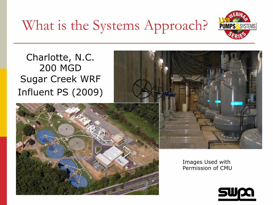
What is the Systems Approach?
Charlotte, N.C. 200 MGD
Sugar Creek WRF Influent PS (2009)
Images Used with Permission of CMU

Available Data for Creation of a Computer Model (Existing Systems)
Pumps Wet Wells
Controls
Pump Station DB Pipes Nodes
Elevation
Parcels
Land use
New Computer
Model
Water Demands Customer Type
Customer Billing Database
GIS
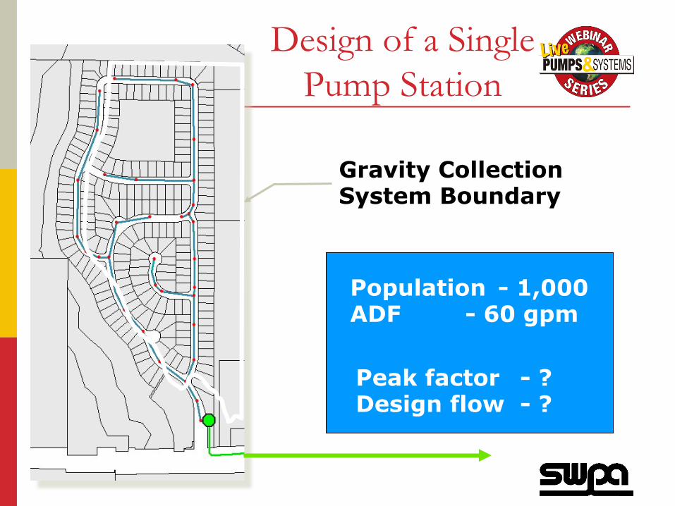
Design of a Single Pump Station
Gravity Collection System Boundary
Peak factor - ? Design flow - ?
Population - 1,000 ADF - 60 gpm
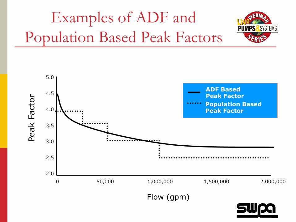
Examples of ADF and Population Based Peak Factors
Peak
Fac
tor
5.0
4.5
4.0
3.5
3.0
2.5
2.0 0 50,000 1,000,000 1,500,000 2,000,000
Flow (gpm)
ADF Based Peak Factor Population Based Peak Factor

Design of a Single Pump Station
Gravity Collection System Boundary
Peak factor - 3.80 Design flow - 230 gpm
Population - 1,000 ADF - 60 gpm

Capacity of pump station #2 must be equal to capacity of pump station #1
Pump Station
#1
Small Systems Are “Easy” to Design
Pump Station
#2

Large Manifolded Systems Are Another Matter

What is the Appropriate Size of the Re-Pump Station ?
Re-pump Station

Re-pump Station
Modeling Practice – Limit Pumps in Operation

Re-pump Station
Modeling Practice – Discount Flows
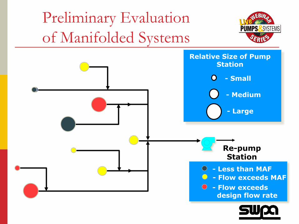
- Small
- Medium
- Large
Relative Size of Pump Station
Preliminary Evaluation of Manifolded Systems
Re-pump Station
- Less than MAF - Flow exceeds MAF - Flow exceeds design flow rate

Over Sizing Facilities can Cause as Much Trouble as Under Sizing
0
20
40
60
80
100
120
140
160
0 1,000 2,000 3,000 4,000 5,000 6,000Pump Flow (gpm)
TD
H (
feet
)
Existing Low Head - HWL
Existing High Head - 2/3D
Pump Performance Curve
2000 PHF 2020 PHF
2010 PHF
18’
~800 gpm

Step by Step Design of a Typical Pump Station

Municipal Design Code Requirements
How many pumps are needed? A typical design should include permanently-installed redundant pumping capacity equaling the largest single pump in a station Firm capacity = with one largest pump out of service

Understand Your Project
New, upgrade or retrofit? New or existing force main? Present and future conditions?

Understand Your Project
• Owner expectations?
• Present and future
conditions?
Demographics? Zoning? Land usage?

What do We do First?
Establish relevant design information • Location of station
Go visit the site!
• Location of discharge point • Electrical requirements
Find out actual line voltages Back-up power needs Utility supply limitations

What do We do First? Establish relevant design information, cont.
• Condition of existing
installation and equipment • Verify static head • Find flow duration data
Daily peak flows Daily min. flows 10, 25, 50 or 100 year flows
• Research existing force main data

Quick and rough design take-off
System head loss calcs • Use 6fps (based on daily peak flow) to rough out a force main size
Calculate FM head loss Add ~5ft for station piping
losses Don’t add unnecessary
safety factors!

Quick and rough design take-off
Establish station design flow based on one of the year daily peak flows
• Duplex station • 2 equal pumps, each sized
for daily peak flow • Standard concept
• Triplex station • 3 equal pumps, each sized
for ½ daily peak flow • May yield better energy
efficiency, more redundancy, and a lower LCC

Quick and rough design take-off • Select pumps for both the duplex
and triplex scenarios • Establish the minimum station inside
diameter based on: HI 9.8 intake design formula
(section 9.8.2.3) I.D. based on the required
minimum active wet pit volume Pump manufacturer’s
recommendations • Decide on preliminary start-stop
levels

D D C CS b w bmin .= ⋅ + ⋅ +25 2
D D C CS b w bmin = ⋅ + ⋅ +2 2
HI 9.8 intake design formula for minimum station ID
Warning: This formula may give a sump diameter that is too small – verify pump start/hour and active sump volume

Station Diameter & Minimum Active Volume • Active volume is the
volume between pump “on” and pump “off” (in a duplex station)
• Min. volume is dictated by allowed motor
starts/hour
Pump On
Pump Off
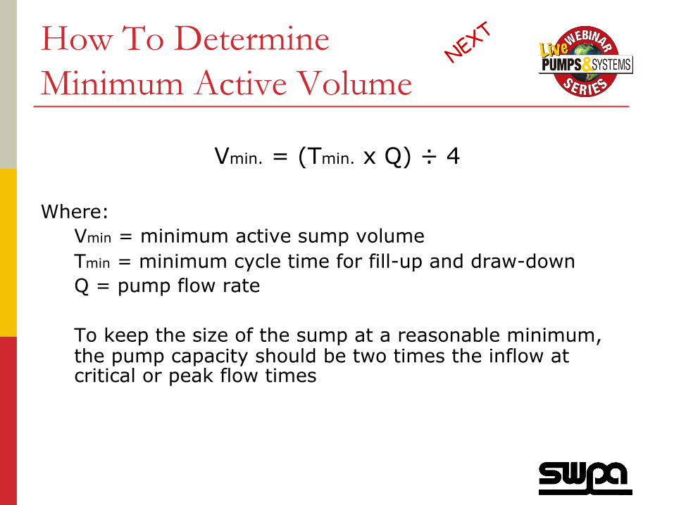
How To Determine Minimum Active Volume
Vmin. = (Tmin. x Q) ÷ 4 Where:
Vmin = minimum active sump volume Tmin = minimum cycle time for fill-up and draw-down Q = pump flow rate To keep the size of the sump at a reasonable minimum, the pump capacity should be two times the inflow at critical or peak flow times

Quick and rough design take-off Make a decision
• Analyze the two station designs based on: Excavation volume ($/c.y.) Pump, valve, piping, accessory, and control cost ($) Energy usage (kW-hr) Redundancy (subjective value?) Complexity and general attractiveness (subjective value?) Calculate station LCC (total $ for life of station)
Initial Cost
Energy Cost
MaintenanceCost
Final Design Process
• Use the “Quick & Rough” design as a basis to lay out final station and FM piping Make adjustments based on findings during the
preliminary pump selections Be flexible with head loss and flow rates so that you can
select pumps that operate close to BEP Use station piping that gives an average liquid velocity of
3-6 fps through fittings Use a FM diameter that satisfies your LCC analysis (often
4-7 fps)
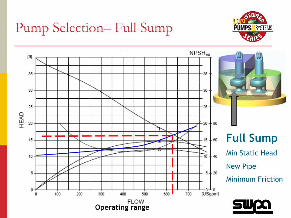
Pump Selection– Full Sump
Operating range
Full Sump Min Static Head
New Pipe
Minimum Friction

Pump Selection – Head loss increase
Operating range
Full Sump Min Static Head
Old Pipe
Maximum Friction

Pump Selection– Empty Sump
Operating range
Empty Sump Min Static Head
New Pipe
Old Pipe

Pump Selection – All Together
5’ draw-down
Operating range
Full sump
Empty sump

Pump Operating Range
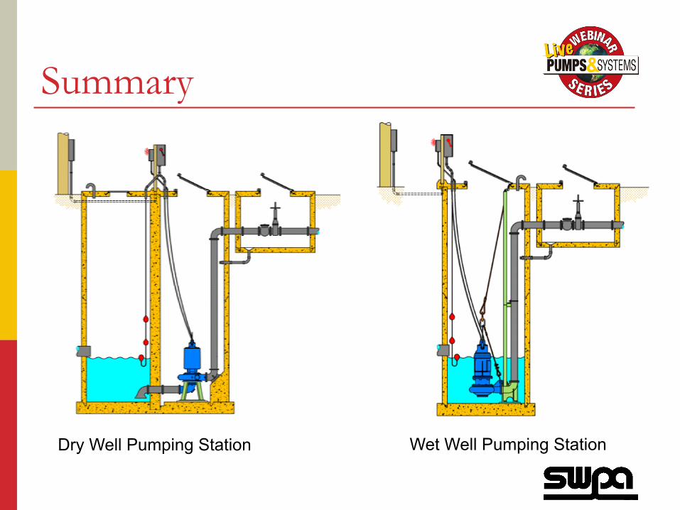
Summary
Dry Well Pumping Station Wet Well Pumping Station

Don’t miss SWPA’s two-day Pumping Systems and Controls Training Seminar –
all based on the systems approach.
April 9-10 – Baltimore, MD
Register by calling 847.681.1868 or visiting swpa.org.
Today’s webinar attendees may receive
½ off their registration.

Q & A To contact today’s presenters, email:
Barry Jongsma - [email protected]
Ernest C. Sturtz - [email protected]
Jim Vukich – [email protected]
Visit pump-zone.com to: • view the answers to all of the questions asked during the Q&A session • access the recording of the webinar or download the presentation
The next webinar in the SWPA series will be on June 19, 2014. More details coming soon.