the standard' speaker system engineering/audio... · inet with locally-purchased materi- als....
TRANSCRIPT

The Williamson circuit became justly fa- mous because it was easy to construct and the results were uniformly good—as long as the tubes were triode-connected. With tetrodes or pentodes, instability often de- veloped. If you have found that trouble, here's how to cure it. See page 20.
Still good after eight years, this loudspeaker enclosure is the subject of so many inquiries that the details of its design and construction are here repeated. See page 26.
THE "STANDARD"' SPEAKER SYSTEM
HIGH-QUALITY TAPE RECORDER AMPLIFIER
SYMPHONY ORCHESTRA REPRODUCTION
MORE ABOUT HUM
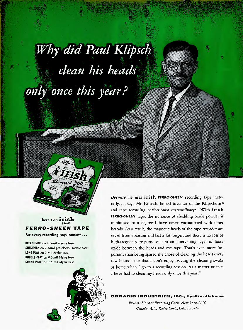
Because he uses irish FERRO-SHEEN recording tape, natu-
rally. ... Says Mr. Klipsch, famed inventor of the Klipschorn®
and tape recording perfectionist extraordinary: "With irish
fERRO-SHEEN tape, the nuisance of shedding oxide powder is
minimized to a degree I have never encountered with other
brands. As a result, the magnetic heads of the tape recorder are
saved from abrasion and last a lot longer, and there is no loss of
high-frequency response due to an intervening layer of loose
oxide between the heads and the tape. That's even more im-
portant than being spared the chore of cleaning the heads every
few hours — not that I don't enjoy leaving the cleaning swabs
at home when 1 go to a recording session. As a matter of fact,
I have had to clean my heads only once this year!"
There's an irish BRAND
FERRO-SHEEN TAPE
for every recording requirement. . ,
GREEN BAND on 1.5-mil acetate base SHAMROCK on 1.3-niil preselected acetate base LONG PLAY on l-mil Mylar base DOUBLE PLAY on 0.3-mil Mylar base SOUND PLATE on 1.5-niil Mylar base
1
ORRADIO I
a ill
DUSTRIES, Inc., Opelika, Alabama
Export: Morhan Exporting Corp., New York, N. Y.
Canada: Atlas Radio Corp., Ltd., Toronto
JANUARY, 1957 VOL. 41, No. 1 Successor to RADIO, Est. 1917.
ENGINEERING MUSIC SOUND REPRODUCTION
C. G. McProud, Editor and Publisher Henry A. Schober, Business Manager Ilarrie K. Richardson, Associate Editor Joan Dioguardi, Assistant Editor Janet M. Durgin, Production Manager Edgar E. Newman, Circulation Director
•MEMBER W<JIItUII o»
III 10:
^t0 O / \ -9
% . */NC-C'
CONTENTS
Audioclinic—Joseph Giovanelli
New Literature
Coming Events
Letters
Editor's Report
Sanford L. Calm, Advertising Director Special Representative— H. Thorpe Covington, 26 East Pearson Street, Chicago 11, 111., DEL 7-0506 Mid West Representative— Sanford B. Cowan, 300 W. 43rd St., New York 36, N. Y. West Coast Representatives— James C. Galloway and J. W. Harbison, 6535 Wilshire Boulevard, Los Angeles 48, Calif.
2
6
6
8
12
High-Quality Tape Recorder Amplifier—Part I—Herman Burstein and Henry C. Pollak
The Care and Treatment of Feedback Audio Amplifiers—W. B. Bernard
Acoustical and Electrical Considerations in Symphony Orchestra Reproduction—Walter T. Selsted and Ross H. Snyder
More About Hum—Harold Reed
The "Standard" Speaker System—C. G. McProud
System Simplicity in Audio—R. G. Chaplick
Record Revue—Edward Tatnall Canby
Audio ETC—Edward Tatnall Canby
About Music—Harold Lawrence
New Products
Industry Notes and People
Advertising Index
15
20
22
25
26
38
42
48
52
58
70
72
AUDIO (title registered U. S. Pat. Off.) is published monthly by Radio Magazines. Inc., Henry A. Schober, President; C. G. McProud, Secretary. Executive and Editorial Offices, 204 Front St., Mineola, N. Y. Subscription rates—U. S., Possessions, Canada and Mexico, $4.00 for one year, $7.00 for two years, all other countries. $5.00 per year. Single copies 50*. Printed in U. S. A. at Lancaster, Pa. All rights reserved. Entire contents copyright 1957 by Radio Magazines, Inc. Entered as Second Class Matter February 9, 1950 at the Post Office, Lancaster, Pa. under the Act of March 3, 1879.
RADIO MAGAZINES, INC., P. O. Box 629, MINEOLA, N. Y.
AUDIO • jANUARY, 1957
NOW THE e (AHptOVVCi/
UNIDYNES
\sb. ^
\s
• 41% higher out- put!
• The perfect microphone choice for use with low- gain P. A. systems and tape recorders . . . in addition to their famed usage in finest quality public address systems.
The Unidynes
are the world's
most widely used
fine microphones.
V0
These unidirectional dynamic microphones are now more than ever your best choice In those Installations where feedback Is a problem, and for all fine-quality public address, theatre- stage sound systems, magnetic recording and remote broadcasting — Indoors or outdoors — where critical standards call for a rugged micro- phone of fine quality.
Another example of the continuous creativity of the Shure Research and Development Laboratories.
55S Unldyne List Price $79.50
556S Broadcast Unidyne List Price $120.00'
SHURE BROTHERS, INC. Microphones Electronic Components
216 HARTREY AVENUE • EVANSTON, ILLINOIS "In Electronics Since 1925"
DO IT YOURSELF
Makes it Possible for
You to Assemble Your Own Hi-Fi System!
AUDIOCLINIC ? ?
JOSEPH CIOVANELLI*
Electro-Voice KD Speaker Cab- inet Kits contain precut wood parts, screws, glue, and step-by-step, illustrated instructions. Assemble the REGENCY corner folded-horn speaker enclosure for Just $73!
Build your own REGENCY cab- inet with locally-purchased materi- als. Buy just the Electro-Voice construction book—$1.00.
Give your REGENCY a fine fur- niture finish—cherry, cordovan ma- hogany, walnut, golden oak, fruit- wood or ebony. Finishing kits, $5. Decorative Metal Trim kit for REGENCY, $6.00. Follow the E-V Building Block Plan, Get The Finest Speaker System on a Budget! Start with Electro- Voice SP15 coaxial loud- speaker, just $85. Step up the quality of your system by adding matched com- ponents as your budget permits—one economical step at a time.
For silky highs, add E-V Model T35 VHF driver, Model AT37 level control, Model X36 crossover.
For smoother, better mid-range response, add Model T25A HF driver with Model 8HD horn. Model AT37 level control and Model X8 crossover.
Add them all together with your basic loudspeak- er and you've got a com- plete, compatible, deluxe, ^ separate three-way speaker system.
Hear the Difference The Electro-Voice Speak-
er SYSTEMS SELECTOR lets you dial the system you JgJ want. You hear the coaxial speaker alone, switch in the rT^i components and hear the improvement as you go. Your nearest Electro-Voice Dealer is the man to see.
Write for Bulletin 2J7-A71
ZleefoVotcz. ELECTRO-VOICE, INC. •BUCHANAN, MICHIGAN
Canada: E-V of Canada Ltd, 1908 Avenue Road, Toronto, Ontario Export: 13 East 40th Street, New York 16, U.S.A. Cables: ARLAB
Lateral and Vertical Recording Q. What is the difference between lat-
eral and vertical recording? Milton Kim- hull, Clearwater, Fla.
A. Regardless of the method, the grooves are identical in appearance un- der conditions of no signal fed to the cutting head. The difference lies in the manner in which the amplitude of the grooves changes with modulation.
The lateral recording process is most commonly used today, and operates in such a way that the needle moves from side to side, causing the pattern of the groove to deviate slightly on either side of its otherwise true spiral. To play such recordings back, a pickup is needed whose construction is such as to allow a voltage to be produced at its output when the needle is caused to move in accordance with the microscopic deviations of the grooves of the disc.
In the lateral recording, the groove is of uniform depth, while in the vertical sys- tem, it is the depth which changes in ac- cordance with the vertical motions of the recording stylus. To play this type of re- cording back, it is necessary to use a pick- up which can be actuated by vertical move- ments of its stylus assembly.
There are advantages and disadvantages to each method. With the lateral method, the limits of the level which can be placed on the disc are determined essentially by the number of lines per inch. Too high a value of signal will cause the walls of ad- jacent grooves to break down, causing ghosts and probable tracking difficulty. However, if the pickup is of a type which can respond only to lateral movements of . the stylus, the vertical components in the motion of the turntable will not generate extraneous voltages in the output of the pickup, meaning that the rumble content of the output will be kept small. The limits of level ou vertical recordings depend upon the depth of the nominal groove, the thick- ness of the acetate and the compliance of the cartridge. The main disadvantage of such a system is that both recording and playback turntables must be free from any vertical motion, since it would immediately be passed on to the pickup and heard as rumble from the loudspeaker. When a re- cording turntable does have such compo- nents, they will be impressed ou the disc material along with the desired recording. It is for this reason that this method has been almost completely supplanted by the lateral method, although it is still used for some special transcriptions.
TRF Receiver Q. What is a JRF receiver? Walter Rus-
sell, Troy, N.Y. A. For purposes of discussion, only com-
mercial broadcast stations between 540 and 1600 ke shall be assumed. Such receivers as this will not perform well at higher fre- quencies.
Each station is assigned by law to a particular frequency. Let us arbitrarily as- sume that at 600 kc there is a station we wish to hear with our TRF receiver. There
are various tuned circuits in such a unit, and to receive this station, all must be tuned to 600 kc. The signal enters the set by means of an antenna and goes from there to the first tuned circuit (LC). Other stations also feed to this circuit, but they tend to be rejected, with the amount of such rejection dependent upon the fre- quency difference between it and the 600 kc which the circuit was set to receive. From here, the signal passes through what is known as an r.f. (radio frequency) am- plifier, thence to a second tuned circuit. This second circuit serves to reject further any unwanted signals; Suppose a signal at 700 kc is 6 db below the desired 600 kc sig- nal. The second circuit will lower the output of the unwanted signal by an additional 6 db, making now for a rejection of 12 db. The rejection would probably be greater than the values used here. The energy has been amplified as mentioned, and may be detected, that is, converted into audio-fre- quency voltages, or may be passed through one or more amplifiers and/or tuned circuits to effect greater rejection prior to detec- tion. Because we are tuning in various radio frequencies, this kind of receiver is said to be of the tuned radio frequency or TRF type.
As has been shown, this receiver tunes broadly, which means that it is subject to considerable adjacent-channel interference. Although this is the case, and in fact, the broadening worsens as the frequency in- creases because of decreasing Q, a broad tuning receiver does have the advantage of there being minimum sideband cutting, leading to a more uniform high-frequency response than is generally achieved in the more common superheterodyne receivers.
Television Sound
Q. 7 have a television receiver whose sound leaves much to he desired. Is there any way for me to feed this into my hi-fi amplifier or my loudspeaker system in such a way as to give me better sound? Thomas Munroe, Las Vegas, Nevada
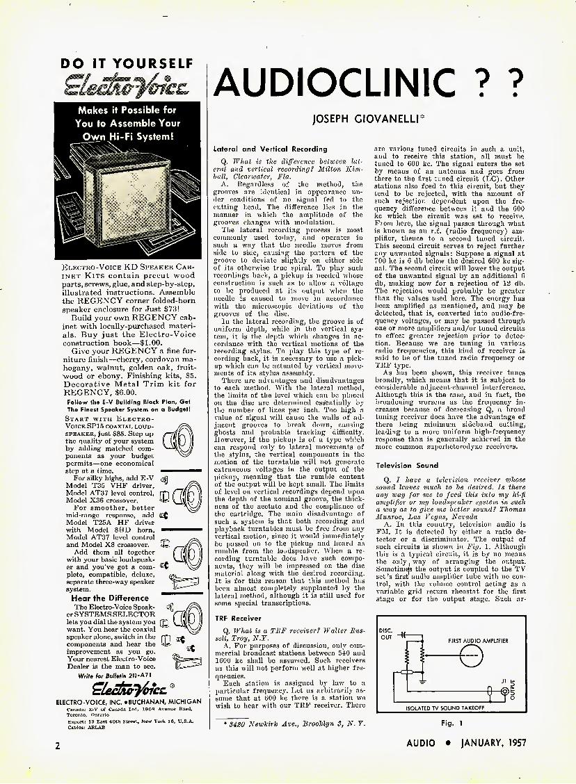
A. In this country, television audio is FM. It is detected by either a ratio de- tector or a discriminator. The output of such circuits is shown in Fig. 1. Although this is a typical circuit, it is by no means the only way of arranging the output. Sometimejs the output is coupled to the TV set's first audio amplifier tube with no con- trol, with the volume control acting as a variable grid return rheostat for the first stage or for the output stage. Such ar-
FIRST AUDIO AMPLIFIER
e
Newkirk Ave., Brooklyn S, N. ¥.
ISOLATED TV SOUND TAKEOFF
Fig. 1
AUDIO • JANUARY, 1957

TEST RESULTS
TESTED: for performance by Audio Instrument Company, Inc., an independent laboratory.
results: Garrard Model 301 tested even better than most professional
disc recording turntables...sets a new standard for transcription machines!
Read Mr. LeBel's report below
3 Stock machines selected at random!
Gentlemen: We have tested the three
Garrard Model 301 Turntables which the undersigned selected at random from sealed unopened cartons in your warehouse stock. These three bore the following serial numbers: 867, 937, 3019. We used a standard Model WB-301 mounting base without modification, a Leak tone arm fitted with their LP cartridge, and a complete Leak preamplifier and power amplifier, model TL/10.
Pickup and amplifier system conformed in response to the RIAA-new AES-riew NARTB curve within ± 1 db.
Standards referred to below are sections of the latest edition. National Association of Radio & Television Broadcasters Recording and Reproducing Standards. Our conclusions are as follows:
Turntable easily adjusted to exact speed!
WOW less than NARTB specifications!
Garrard Serial No. 867 937
3019
% .17 .13 .12
Rumble less than most professional
recording turntables!
Now there's a Garrard for every high-fidelity system
RC98 RCS8 RC121 Super Changer Deluxe Changer Mixer Changer $67.50 $54.50 $42.50 301 Model T Turntable Manual Player $89.00 $32.50
Signal to Rumble Ratio Using Reference Velocity of 7 cm/sec at 500 cps
This reference velocity cor- responds to the NARTB value of 1,4 cm/sec at 100 cps.
Garrard Serial No. 867 937
3019
Rumble: checked by official NARTB standard method (—35 db. min.)
—52 db.!
DB 52 49 49
The results shown are all better than the 35 db broadcast repro- ducing turntable minimum set by NARTB section 1.12. In fact they are better than most professional disc recording turntables.
Measurements were made in accordance with NARTB spe- cification 1.05.01, using a stro-
boscope disc. In every case, speed could be adjusted, to be in compliance with section 1.05, i.e. within 0.3%. In fact, it could easily be adjusted to be exactly correct.
Signal to Rumble Ratio Using Reference Velocity of 20 cm/sec at 500 cps
Rumble; checked by Manufacturer A's methods —61 db.!
Measurements were made at 33Vi rpm in accordance with NARTB specification 1,11,
which calls for not over 0,20% deviation. These values substantially agreed with those given on Garrard's individual test sheets which are included with each motor.
Garrard Serial No. 867 937
3019
DB 61 58 58
Rumble: checked by Manufacturer B's methods -84.1 db.!
We include this second table to facilitate comparison because some turntable manufacturers have used their own non-stand- ard reference velocity of 20 cm/sec, at an unstated frequency. If this 20 cm/sec were taken at 100 cps instead, we would add an additional 23.1 db to the figures just above. This would then show serial number 867 to be 84,1 db.
Measurements were made in accordance with sections 1,12 and 1.12.01, using a 10 to 250 cps band pass filter, and a VU
meter for indication. Attenuation was the specified 12 db per octave above 500 cps and 6 db per octave below 10 cps. Speed was 331/3 rpm.
Of greatest importance! Always consider these vital factors to evaluate any manufacturer's claim.
It will be seen from the above that no rumble figures are meaningful unless related to the reference velocity and the ref- erence frequency. Furthermore, as stated in NARTB specifica- tion 1.12,01, results depend on the equalizer and pickup character- istics, as well as on the turntable itself. Thus, it is further necessary to indicate, as we have done, the components used in making the test. For example, a preamplifier with extremely poor low frequency response would appear to wipe out all rumble and lead to the erro- neous conclusion that the turntable is better than it actually is. One other factor to consider is the method by which the turntable is mounted when the test is made. That is why our tests were made on an ordinary mounting base available to the consumer.
Very truly yours. ' O- J'-
AUDIO INSTRUMENT COMPANY, INC. C. J. LeBel
Write for free High-Fidelity Plan Book, Dept.ca-17 Garrard Sales Corp., Port Washington, N. Y.
AUDIO • JANUARY, 1957 3
rangements as this are used for the sake of economy, a big factor in a competitive market. It is for this reason, too, that little attention is given to the sound in most television receivers.
It is always best, where possible, to connect the input lead to your external am- plifier across the detector. With the circuit arrangement here shown, the amplifier is always fed by the discriminator, regard- less of the setting of the volume control on the TV set itself.
If the function switch of your pream- plifier is turned to a source of signal other than the TV sound, it is likely that no sound will be heard even from the TV set's own speaker, since on most preamplifiers, the function switch shorts all inputs ex- cept the one in use. If this feature is ob- jectionable, wire the set according to Fig.
2. This places a resistance in series with the "hot" lead of the discriminator, so that, although no sound can enter the pre- amplifier when the function switch is reset, only a partial short will occur at the TV input. Although the volume from the set's internal speaker will probably be some- what less than normal, sufficient sound level will still be available. The trouble with this system is that the additional re- sistor, B,,, will form a voltage divider be- tween itself and the grid resistor of the preamplifier, with the possibility of not supplying enough voltage to drive the pre- amplifier to a satisfactory output level. If this should be the ease, or if the lead from the TV receiver and the preamplifier must be fairly long, then it might be well to add a cathode follower. The input of the cathode follower is placed across the dis-
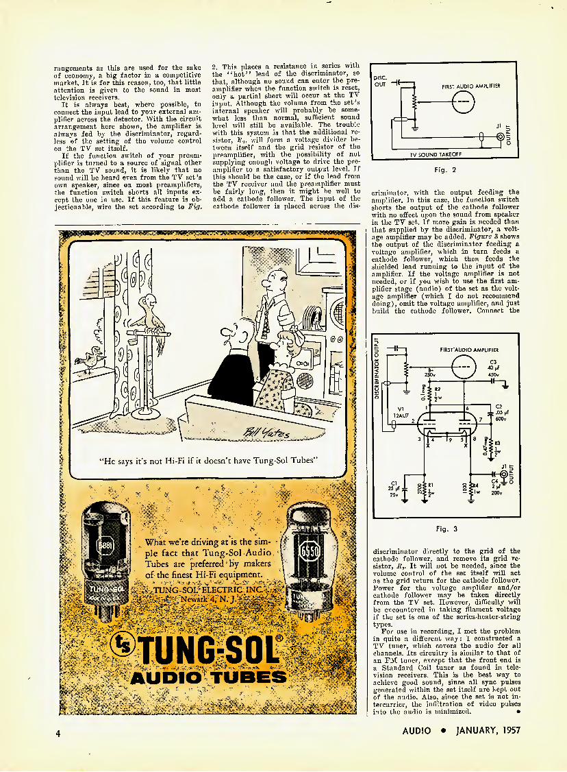
©TUNG-SOL'
AUDIO TUBES
TUNG-SOL ELECTRIC INC Newark 4, N. J.
What we're driving at is the sim- ple fact that Tung-Sol Audio Tubes are preferred by makers of the finest Hi-Fi equipment.
Fig. 2
criminator, with the output feeding the amplifier. In this case, the function switch shorts the output of the cathode follower with no effect upon the sound from speaker in the TV set. If more gain is needed than that supplied by the discriminator, a volt- age amplifier may be added. Figure 3 shows the output of the discriminator feeding a voltage amplifier, which in turn feeds a cathode follower, which then feeds the shielded lead running to the input of the amplifier. If the voltage amplifier is not needed, or if you wish to use the first am- plifier stage (audio) of the set as the volt- age amplifier (which I do not recommend doing), omit the voltage amplifier, and just build the cathode follower. Connect the
Fig. 3
discriminator directly to the grid of the cathode follower, and remove its grid re- sistor, R,. It will not be needed, since the volume control of the set itself will act as the grid return for the cathode follower. Power for the voltage amplifier and/or cathode follower may be taken directly from the TV set. However, difficulty will be encountered in taking filament voltage if the set is one of the series-heater-string types.
For use in recording, I met the problem in quite a different way: I constructed a TV tuner, which covers the audio for all channels. Its circuitry is similar to that of an FM tuner, except that the front end is a Standard Coil tuner as found in tele- vision receivers. This is the best way to achieve good sound, since all sync pulses generated within the set itself are kept out of the audio. Also, since the set is not in- tercarrier, the infiltration of video pulses into the audio is minimized. •
4 AUDIO • JANUARY, 1957
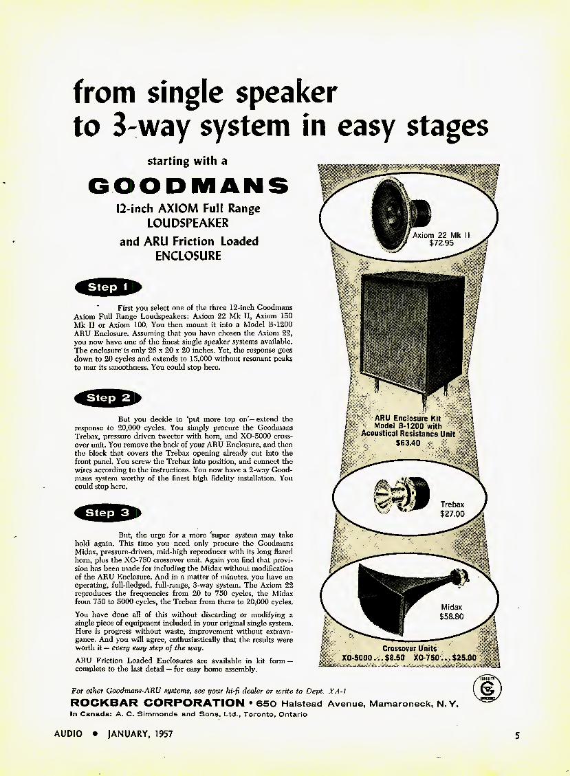
from single speaker
to 3'Way system in easy stages
Axiom 22 Mk II $72.95
ARU Enclosure Kit Model B-120Q with
Acoustical Resistance Unit $63.40
Trebax $27.00
Midax $58.80
Crossover Units XO-5000 ...$8.50 XO-750...$25.00
. , " , .
starting with a
GOODMAN
12-inch AXIOM Full Range
LOUDSPEAKER
and ARU Friction Loaded
ENCLOSURE
First you select one of the three 12-inch Goodmans Axiom Full Range Loudspeakers: Axiom 22 Mk II, Axiom 150 Mk II or Axiom 100. You then mount it into a Model B-1200 ARU Enclosure. Assuming that you have chosen the Axiom 22, you now have one of the finest single speaker systems available. The enclosure'is only 26 x 20 x 20 inches. Yet, the response goes down to 20 cycles and extends to 15,000 without resonant peaks to mar its smoothness. You could stop here.
But you decide to 'put more top on'— extend the response to 20,000 cycles. You simply procure the Goodmans Trebax, pressure driven tweeter with horn, and XO-5000 cross- over unit. You remove the back of your ARU Enclosure, and then the block that covers the Trebax opening already cut into the front panel. You screw the Trebax into position, and connect the wires according to the instructions. You now have a 2-way Good- mans system worthy of the finest high fidelity installation. You could stop here.
But, the urge for a more 'super system may take hold again. This time you need only procure the Goodmans Midax, pressure-driven, mid-high reproducer with its long flared horn, plus the XO-750 crossover unit. Again you find that provi- sion has been made for including the Midax without modification of the ARU Enclosure. And in a matter of minutes, you have an operating, full-fledged, full-range, 3-way system. The Axiom 22 reproduces the frequencies from 20 to 750 cycles, the Midax from 750 to 5000 cycles, the Trebax from there to 20,000 cycles.
You have done all of this without discarding or modifying a single piece of equipment included in your original single system. Here is progress without waste, improvement without extrava- gance. And you will agree, enthusiastically that the results were worth it — every easy step of the way. ARU Friction Loaded Enclosures are available in kit form — complete to the last detail — for easy home assembly.
For other Goodmans-ARU systems, see your hi-fi dealer or write to Dept. XA-1
ROCKBAR CORPORATION • 650 Halstead Avenue, Mamaroneck, N. Y. In Canada: A. C. Simmonds and Sons, Ltd., Toronto, Ontario
AUDIO • JANUARY, 1957 5
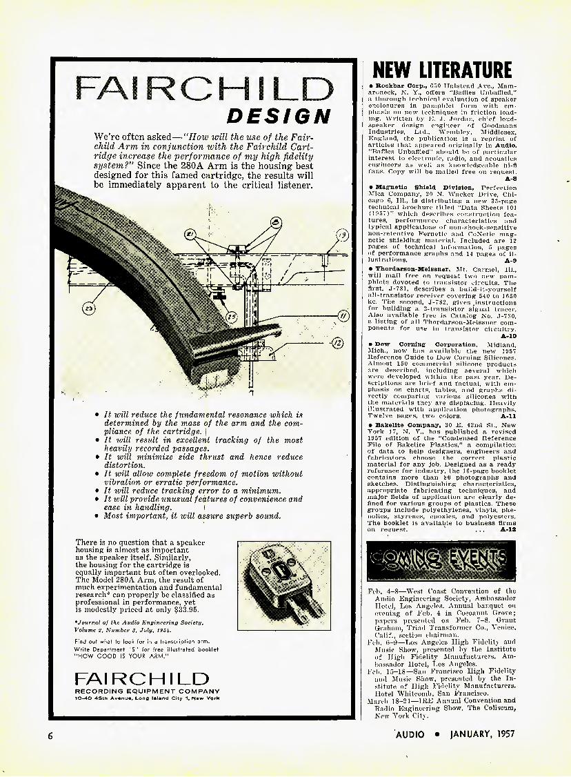
FAIRCHILD
DESIGN
• It will reduce the fundamental resonance ivhich is determined by the mass of the arm and the com- pliance of the cartridge.
• It will residt in excellent tracking of the most heavily recorded passages.
• It will minimize side thrust and hence reduce distortion.
• It will alloiv complete freedom of motion without vibration or erratic performance.
• It ivill reduce tracking error to a minimum. • It ivill provide unusual features of convenience and
ease in handling. • Most important, it will assure superb sound.
There is no question that a speaker housing is almost as important as the speaker itself. Similarly, the housing for the cartridge is equally important but often overlooked. The Model 280A Arm, the result of much experimentation and fundamental research* can properly be classified as professional in pei'formance, yet is modestly priced at only $33.95. * Journal of the Audio Engineering Society, Volume 2, Number 3, July, 195Jt. Find out what to look for in a transcription arm. Write Department "5" for free illustrated booklet "HOW GOOD IS YOUR ARM."
FAIRCHILD RECORDING EQUIPMENT COMPANY 10-40 45th Avenue, Long Island City 1, New York
NEW LITERATURE • Rockbar Corp., 650 Halstead Ave., Mam- aroneck, N. Y., offers "Baffles Unbaffled," a thorough technical evaluation of speaker enclosures in pamphlet form with em- phasis on new techniques in friction load- ing. Written by E. J. Jordan, chief loud- speaker design engineer of Goodmans Industries, Ltd., Wembley, Middlesex, England, the publication is a reprint of articles that appeared originally in Audio. "Baffles Unbaffled" should be of particular interest to electronic, radio, and acoustics engineers as well as knowledgeable hi-fi fans. Copy will be mailed free on request.
A-8 • Magnetic Shield Division, Perfection Mica Company, 20 N. Wacker Drive, Chi- cago 6, 111., is distributing a new 33-page technical brochure titled "Data Sheets 101 (1 957)'" which describes construction fea- tures, performance characteristics and typical applications of non-shock-sensitive non-retentive Fernetic and CoNetic mag- netic shielding material. Included are 12 pages of technical information, 5 pages of performance graphs and 14 pages of il- lustrations. A-9 • Thordarson-Meissner, Mt. Carmel, 111., will mail free on request two new pam- phlets devoted to transistor circuits. The first, J-7S1, describes a build-it-yourself all-transistor receiver covering 540 to 1650 kc. The second, J-7S2, gives .instructions for building a 2-transistor signal tracer. Also available free is Catalog No. .1-780, a listing of all Thordarson-Meissner com- ponents for use in transistor circuitry.
A-10 • Dow Corning- Corporation, Midland, Mich., now has available the new 1957 Reference Guide to Dow Corning Silicones. Almost 150 commercial silicone products are described, including several which were developed within the past year. De- scriptions are brief and factual, with em- phasis on charts, tables, and graphs di- rectly comparing various silicones with the materials they are displacing. Heavily illustrated with application photographs. Twelve pages, two colors. A-ll • Bakelite Company, 30 E. 42nd St., New York 17, N. Y., has published a revised 1957 edition of the "Condensed Reference File of Bakelite Plastics," a compilation of data to help designers, engineers and fabricators choose the correct plastic material for any job. Designed as a ready reference for industry, the 16-page booklet contains more than 80 photographs and sketches. Distinguishing characteristics, appropriate fabricating techniques, and major fields of application are clearly de- fined for various groups of plastics. These groups include polyethylenes, vinyls, phe- nolics, styrenes, epoxies, and polyesters. The booklet is available to business firms on request. . . . A-12
Feb. 4-8—West ('oast Convention of the Audio Engineering Society, Ambassador Hotel, Los Angeles. Annual banquet on evening of Feb. 4 in Cocoanut Grove; papers presented on Feb. 7-8. Grant Graham, Triad Transformer Co., Venice, Calif., section chairman.
Fob. 6-9—Los Angeles High Fidelity and Music Show, presented by the Institute of High Fidelity Manufacturers. Am- bassador Hotel, Los Angeles.
Feb. 15-18—San Francisco High Fidelity and Music Show, presented by the In- stitute of High Fidelity Manufacturers. Hotel Whitcomb, San Francisco.
March 18-21—IRE Annual Convention and Radio Engineering Show. The Coliseum, New York City.
We're often asked—"How will the use of the Fair- child Arm in conjunction with the Fairchild Cart- ridge increase the performance of my high fidelity system?" Since the 280A Arm is the housing best designed for this famed cartridge, the results will be immediately apparent to the critical listener.
6 AUDIO • JANUARY, 1957
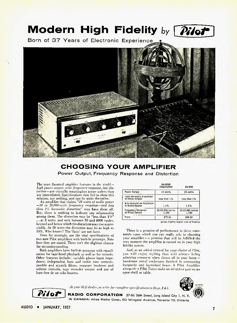
Modern High Fidelity by Q/V/o/*
CHOOSING YOUR AMPLIFIER
Power Output, Frequency Response and Distortion
The most flaunted amplifier features in the world — high power output, wide jrequency response, low1 dis- torlion — are virtually meaningless terms unless they are interrelated. Specifications that fail to show this relation, say nothing, and can be quite deceptive.
An amplifier that claims "20 watts of audio power — 20 to 20.000-cycle jrequenry response —and less than 1% harmonic distortion" may have them all. But. there is nothing to indicate any relationship among them. The distortion may be "less than 1%" ...at 2 watts, and only between 50 and 8000 cycles, beyond and below which the distortion may rise appre- ciably. At 20 watts the distortion may be as high as 10%. Who knows? The 'facts' are not facts.
Here for example, are the vital specifications of two new Pilot amplifiers with built-in preamps. Note how they are staled. There isn't the slightest chance for misunderstanding.
Both amplifiers have built-in preamps with equali- zation for tape-head playback as well as for records. Other features include: variable phono input impe- dance. independent bass and treble tone controls, rumble and scratch filters, separate loudness and volume controls, tape recorder output and use of hum-free dc on tube heaters.
AA-903B (illustrated) AA-920
Power Output 14 watts 20 watts Total Harmonic Distortion at Rated Output less than 1% less than 1% Intermodulation Distortion at Rated Output 1.5% 1.5% Frequency Response at Rated Output
20-20,000 cycles -±ldb
20-20,000 cycles ±ldb
Price $79.95 $99.50 prices slightly higher west of Rockies
There is a promise of performance in these state- ments upon which you can really rely in choosing your amplifier—a promise that will be fulfilled the very moment the amplifier is turned on in your high fidelity system.
And, as an added reward for your choice of Pilot, you will enjoy styling that will always bring admiring comment when shown off in your home— handsome metal enclosures finished in contrasting burgundy and burnished brass. A Pilot Amplifier alongside a Pilot Tuner make an attractive pair on an open shelf or table.
j/V/o/-
At your hi-fi dealer, or write for complete specifications to Dept. FA-I.
CORPORATION 37-06 36fh Street, Long Island City 1, N. Y. ' IN CANADA: Atlas Radio Corp., SO Wingold Avenue, Toronto 10, Ontario
AUDIO • JANUARY, 1957 7
/o^ yoai
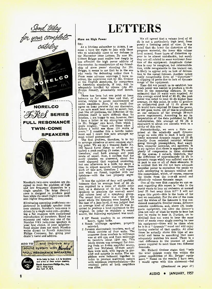
NORELCO
SERIES
FULL RESONANCE
TWIN-CONE
SPEAKERS
Norelco's twin-cone speakers are de- signed to meet the problem of high and low frequency dispersion in a single speaker. The large (heavy) cone is designed to produce good bass while the small (light) cone radi- ates higher frequencies. Eliminating operating inefficiency ex- perienced in multiple speaker cross over systems, Norelco's twin-cone is driven by a single voice coil—produc- ing a flat response with exceptional reproduction of transients. Based on economy and value any one of the Norelco FRS twin-cone speakers is your best choice. If your neighbor- hood dealer does not stock Norelco write direct to North American Philips Company, Inc. giving your dealer's name and address.
ADD TO I
and improve any sound system withtforetcff ♦FULL RESONANCE SPEAKERS
Write today to Dept. A-l for brochures and orices of these unique speakers. North American Philips Co.# Inc. 100 E. 42nd Street New York 17, N.Y.
LETTERS
More on High Power Sir:
As a lifetime subscriber to Audio, I as- sume I have the right to join with those who so admirably came to my defense in the November issue Letters. By now Mr. Gilbert Briggs must realize how deeply he has offended the high power addicts of this country. In consideration of my friend- ship of some years' standing for Mr. Briggs, it seems to me that he is the one who needs the defending rather than I. Prom some advance warnings I have re- ceived, the aspersions cast by Mr. Greiner at the English standards, by comparison to American standards, if any, will be adequately handled by others. {By Mr. Briggs himself, presumably next month. Ed.)
There has been but one point at issue between us for some time and that, of course, relates to power requirements of audio amplifiers. Now, if we could first agree on some premise for our discussion, I am sure much heat would be saved; but, just like all problems, the definition of the problem itself is more difficult than its solution. I am happy to say, however, that I have a letter in my strong-box written in Mr. Briggs' own hand, from which I quote roughly, '' there are times when I believe I could use those 120 watts of yours." I consider this a terrific indict- ment and I count this note amongst my most valued possessions!
The first problem, therefore, is to try to arrange ourselves at some common start- ing point. We set up a General Radio No. 759 Sound Level Meter to which we at- tached a peak-reading db meter. We could, therefore, read both average and peak levels of sound. Now, I confess that for every question we answered, about five more appeared that required answering, but one afternoon is a little too short a time to expect accurate conclusions from work of this sort, therefore I will report just what we found, together with our opinions—with the two properly segre- gated.
It was the opinion of four well qualified listeners that an average level of 95 db was required in a room of 15,600 cubic feet, at a distance of 25 feet from the speakers to simulate the over-all sound and volume level of a symphony group. The sound level meter was read at the point where the listeners were located. In the case of a jazz band, it was judged that an average level of about 105 db was re- quired to produce a level equivalent to the original. In order to stipulate a sound source, the following equipment was used;
8 12" Bozak woofers in an extremely heavy, tight baffle.
4 Bozak ' midrange speakers, properly oriented.
2 Janszen electrostatic tweeters, each of which consists of four units. The crossover from woofers to midrange was at 400 cps, and from midrange to tweeters about 1200 cps. This whole system was arranged for driv- ing from an 8-ohm amplifier source, and two Mclntosh 60-watt ampli- fiers were used, with inputs in par- allel and outputs in series. The am- plifiers were balanced together in order to produce maximum output with minimum intermodulation—the overload point of both amplifiers was alike.
We all agreed that a volume level of 96 db is not a particularly high level, from purely a listening point of view. It was noted that the lower the distortion of the program material, the lower this volume level seemed. Some types of distortion ap- pear to be almost undefinable, but surely they are all related to some nonlinear func- tion of the equipment. Amplitude distor- tion is easy to recognize, but intermodula- tion, while recognizable to the trained ear, is likely to appear only as lack of delinea- tion to the casual listener. Another rather easily recognizable form of '' distortion'' is clipping of peaks due to lack of dynamic range of the equipment.
Time did not permit us to establish how much power was needed to produce a 95-db level at the measuring distance. It was estimated that 30 watts were required. At this average sound level of 95 db, the peak meter was noted to read 13 db higher than average. At this point, in order to produce an undistorted peak of 13 db above 95 db would have required 20 times the power, or 600 peak watts. All of this is predicated on our estimate of the average 30-watt power requirement. According to my in- terpretation of the data published by Bell Laboratories, this average of 95 db is equivalent to about one acoustic watt in a cavity of this size.
Parenthetically, we were a little sur prised at the relatively small dynamic range we were able to read. I have prev- iously measured dynamic ranges of 26 db directly from recorded material without going through preamplifiers, final ampli- fiers, crossover networks, and speakers. It is my opinion that there is opportunity for plenty of compression in these elements of the system. I submit, therefore, that the difference of approximately 13 db in dynamic range which was suffered was due in part to one or all of these elements. It is evident that we did not have adequate amplifier power to reproduce the peaks we were attempting to measure without aud- ible compression, which, of course, removes the bloom from the over-all sound and effectively reduces dynamic range.
One of the very first remarks we can ex- pect regarding this report is "who in the world wants to hear an orchestra at normal level 25 feet away from it?" I will not argue this point-—this is the basis of the test we conducted. Por the size of the room and the wishes of the listeners it was con- sidered reasonable. Smaller rooms, different acoustic conditions, and, above all, inade- quate equipment, can alter the listener's idea not only of what he wants to hear but how he wants to hear it. Purther, an in- dividual does not want to hear the same kind of music every single evening he uses his equipment—there will be times when he is in a "dynamic" mood and will enjoy having material of that quality. At other times lie actually shuns this type of ma- terial and turns to something that more adequately matches his mood. There is a vast difference in the amount of audio power required to meet these two different demands.
Mr. Richard Greiner states that "only the wind quintet music lies within the power capabilities of Mr. Briggs' equip- ment." Based on the results I have seen, I would agree with this statement—but
{Continued on page S7)
AUDIO • JANUARY, 1957
ELECTRONICS
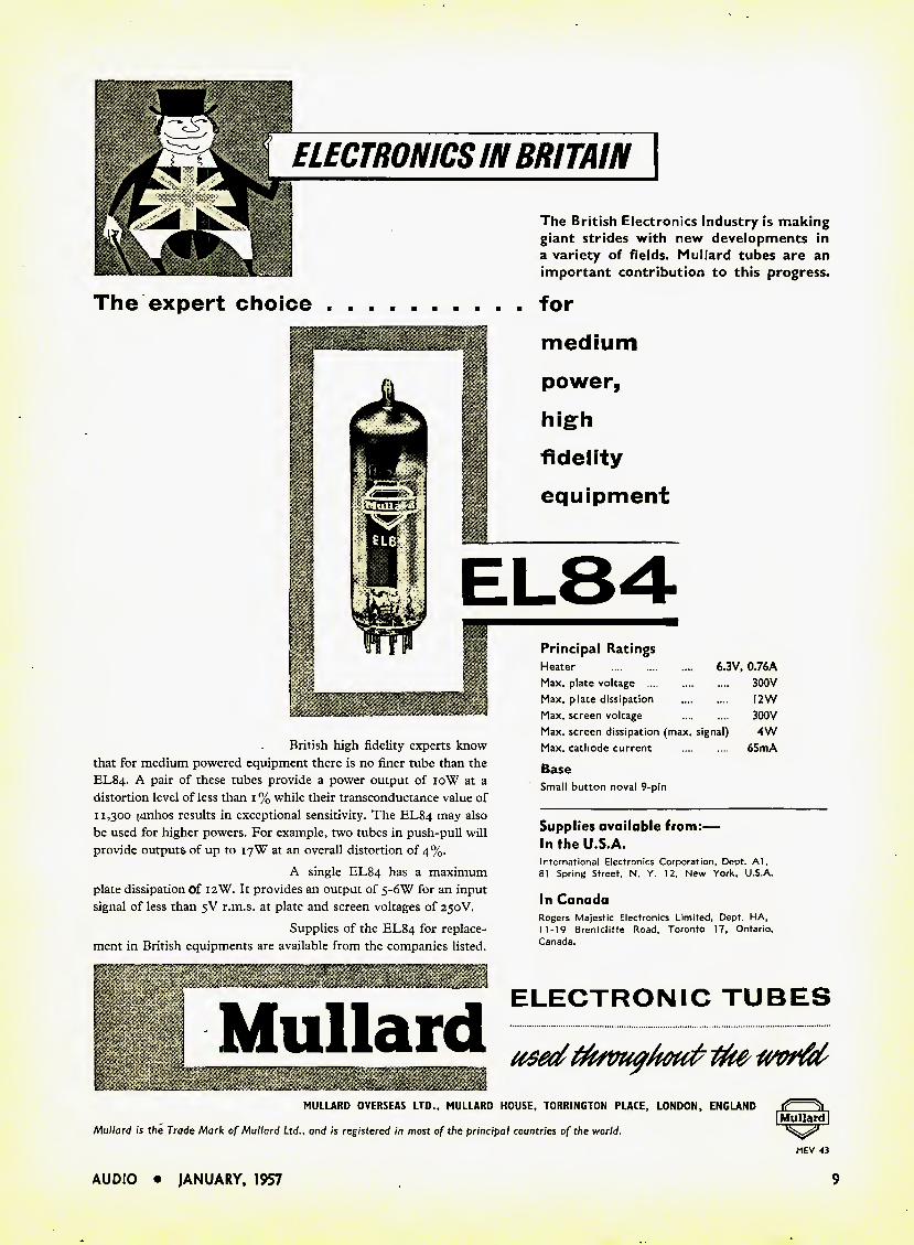
The British Electronics Industry is making giant strides with new developments in a variety of fields. Mullard tubes are an important contribution to this progress.
The expert choice for
medium
power,
high
fidelity
equipment
British high fidelity experts know that for medium powered equipment there is no finer tube than the EL84. A pair of these tubes provide a power output of 10W at a distortion level of less than 1 % while their transconductance value of 11,300 [imhos results in exceptional sensitivity. The EL84 may also be used for higher powers. For example, two tubes in push-pull will provide outputs of up to 17W at an overall distortion of 4%.
A single EL84 has a maximum plate dissipation Of 12W. It provides an output of 5-6W for an input signal of less than 5V r.m.s. at plate and screen voltages of 250V.
Supplies of the EL84 for replace- ment in British equipments are available from the companies listed,
i
r M Mullard
Principal Ratings Heater Max. plate voltage Max. plate dissipation Max. screen voltage Max. screen dissipation (max. signal) Max. cathode current
Base Small button noval 9-pin
6.3V, 0.76A 300V I2W 300V 4W
6SmA
Supplies available from:— In the U.S.A. International Electronics Corporation, Dept. Al. 81 Spring Street, N. Y. 12, New York. U.S.A.
In Canada Rogers Majestic Electronics Limited, Dept. HA, 11-19 Brentcliffe Road. Toronto 17. Ontario, Canada.
ELECTRONIC TUBES
MULLARD OVERSEAS LTD., MULLARD HOUSE, TORRINGTON PLACE, LONDON, ENGLAND I Mullard |
Mullard is the Trade Mark of Mullard Ltd., and is registered in most of the principal countries of the world. ^ MEV 43
AUDIO JANUARY, 1957
cm & ..
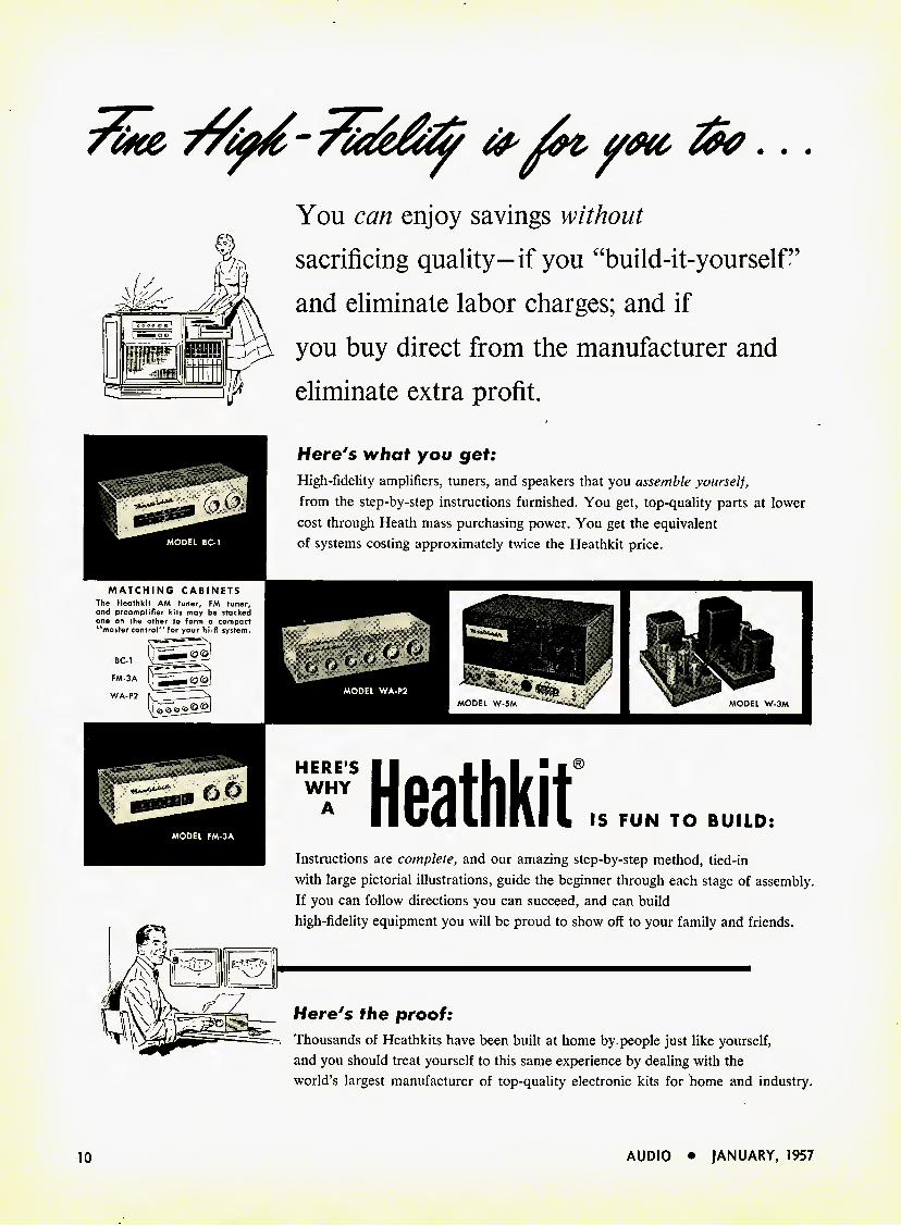
You can enjoy savings without
sacrificing quality-if you "build-it-yourself
and eliminate labor charges; and if
you buy direct from the manufacturer and
eliminate extra profit.
MATCHING CABINETS
Here's what you get:
High-fidelity amplifiers, tuners, and speakers that you assemble yourself,
from the step-by-step instructions furnished. You get, top-quality parts at lower
cost through Heath mass purchasing power. You get the equivalent
of systems costing approximately twice the Heathkit price.
HERE'S WHY
A Heathkit IS FUN TO BUILD:
Instructions are complete, and our amazing step-by-step method, tied-in
with large pictorial illustrations, guide the beginner through each stage of assembly.
If you can follow directions you can succeed, and can build
high-fidelity equipment you will be proud to show off to your family and friends.
Here's the proof:
Thousands of Heathkits have been built at home by people just like yourself,
and you should treat yourself to this same experience by dealing with the
world's largest manufacturer of top-quality electronic Jcits for home and industry.
MODEL BC-1
The Heathkit AM tuner, FM tuner, and preamplifier kits may be stacked one on the other to form a compact "master control" for your hi-fi system.
BC-1 FM-3A WA-P2 MODEL W-5M MODEL W-3M
10 AUDIO • JANUARY, 1957
*269.5
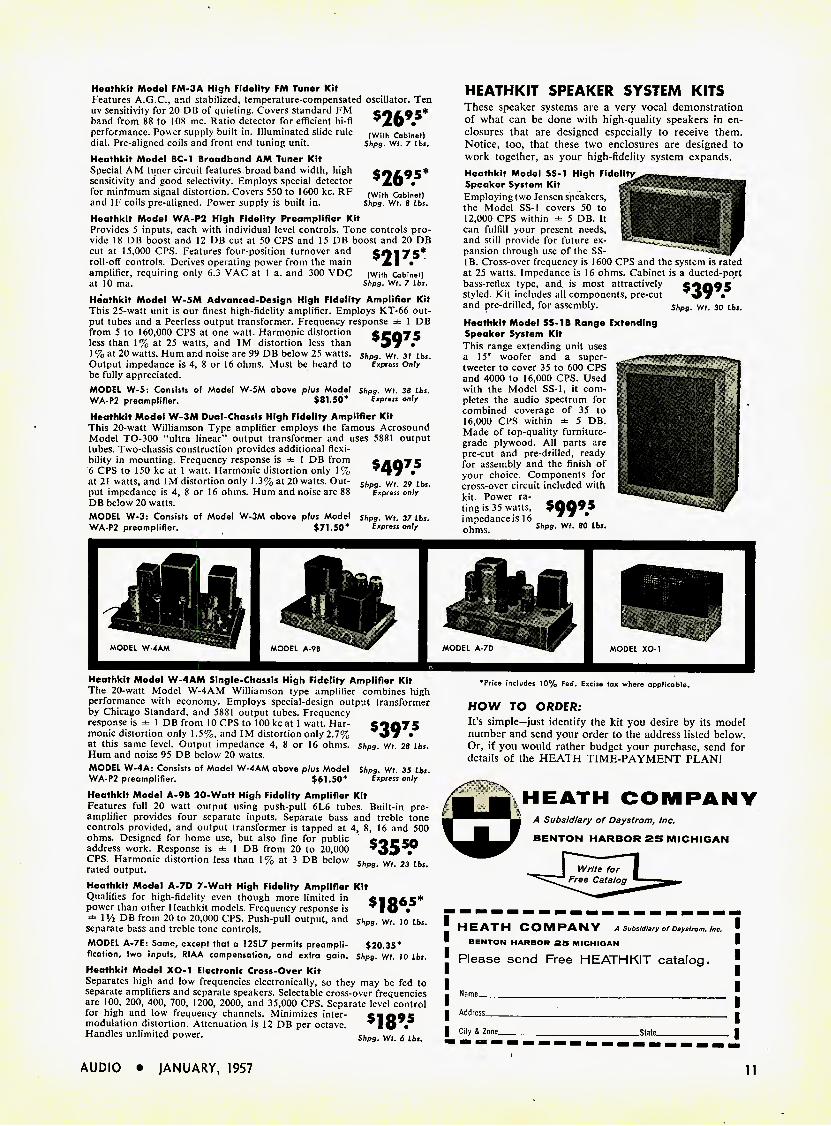
Heothkit Model FM-3A High Fidelity FM Tuner Kit Features A.G.C., and stabilized, temperature-compensated oscillator. Ten uv sensitivity for 20 DB of quieting. Covers standard FM band from 88 to 108 mc. Ratio detector for efficient hi-fi XO • performance. Power supply built in. Illuminated slide rule (With cabinet) dial. Pre-aligned coils and front end tuning unit. Shpg. wt. 7 lbs. Heatlikit Model BC-1 Broadband AM Tuner Kit Special AM tuner circuit features broad band width, high sensitivity and good selectivity. Employs special detector for mintmum signal distortion. Covers 550 to 1600 kc. RF (with Cabinet) and IF coils pre-aligncd. Power supply is built in. Shpg. Wt. 8 lbs. Heathkit Model WA-P2 High Fidelity Preamplifier Kit Provides 5 inputs, each with individual level controls. Tone controls pro- vide 18 DB boost and 12 DB cut at 50 CPS and 15 DB boost and 20 DB cut at 15,000 CPS. Features four-position turnover and SOI 75* roll-off controls. Derives operating power from the main XI* amplifier, requiring only 6.3 VAC at 1 a. and 300 VDC (with Cabinet) at 10 ma. Shpg. wt. 7 tbs. Heathkit Model W-5M Advanced-Design High Fidelity Amplifier Kit This 25-watt unit is our finest high-fidelity amplifier. Employs KT-66 out- put tubes and a Peerless output transformer. Frequency response ± 1 DB from 5 to 160,000 CPS at one watt. Harmonic distortion less than 1% at 25 watts, and 1M distortion less than 1% at 20 watts. Hum and noise are 99 DB below 25 watts. Output impedance is 4, 8 or 16 ohms. Must be heard to be fully appreciated. MODEL W-5: Consists of Model W-5M above plus Model WA-P2 preamplifier. $81.50*
$597.5
Shpg. Wt. 31 Lbs. Express Only
Shpg. Wt. 38 Lbs. Express only
Heathkit Model W-3M Dual-Chassis High Fidelity Amplifier Kit This 20-watt Williamson Type amplifier employs the famous Acrosound Model TO-300 "ultra linear" output transformer and uses 5881 output tubes. Two-chassis construction provides additional flexi- bility in mounting. Frequency response is 1 DB from 6 CPS to 150 kc at 1 watt. Harmonic distortion only 1% at 21 watts, and IM distortion only 1.3% at 20 watts. Out- put impedance is 4, 8 or 16 ohms. Hum and noise are 88 DB below 20 watts. MODEL W-3: Consists of Model W-3M above plus Model WA-P2 preamplifier. $71.50*
$4975
Shpg. Wt. 29 Lbs. Express only
Shpg. Wt. 37 Lbs. Express only
HEATHKIT SPEAKER SYSTEM KITS These speaker systems are a very vocal demonstration of what can be done with high-quality speakers in en- closures that are designed especially to receive them. Notice, too, that these two enclosures are designed to work together, as your high-fidelity system expands.
Heathkit Model SS-1B Range Extending Speaker System Kit This range extending unit uses a 15' woofer and a super- tweeter to cover 35 to 600 CPS and 4000 to 16,000 CPS. Used with the Model SS-I, it com- pletes the audio spectrum for combined coverage of 35 to 16,000 CPS within ± 5 DB. Made of top-quality furniture- grade plywood. All parts are pre-cut and pre-drilled, ready for assembly and the finish of your choice. Components for cross-over circuit included with kit. Power ra- _ _ _ _ _ ting is 35 watts, $009^5 impedance is 16 ohms. Shpg. Wt. 80 Lbs.
MODEL A-7D MODEL W-4AM MODEL XO-1
Heathkit Model W-4AM Single-Chassis High Fidelity Amplifier Kit The 20-watt Model W-4AM Williamson type amplifier combines high performance with economy. Employs special-design output transformer by Chicago Standard, and 5881 output tubes. Frequency response is ± 1 DB from 10 CPS to 100 kc at 1 watt. Har- monic distortion only 1.5%, and IM distortion only 2.7% at this same level. Output impedance 4, 8 or 16 ohms. Hum and noise 95 DB below 20 watts. MODEL W-4A: Consists of Model W-4AM above plus Model WA-P2 preamplifier. $61.50*
$397.5
Shpg. Wt. 28 Lbs.
Shpg. Wt. 35 Lbs. Express only
Heathkit Model A-9B 20-Watt High Fidelity Amplifier Kit Features full 20 watt output using push-pull 6L6 tubes. Built-in pre- amplifier provides four separate inputs. Separate bass and treble tone controls provided, and output transformer is tapped at 4, 8, 16 and 500 ohms. Designed for home use, but also fine for public OP CO address work. Response is ± 1 DB from 20 to 20,000 35 • CPS. Harmonic distortion less than 1% at 3 DB below rated output. Shpg, Wt. 23 Lbs.
Heathkit Model A-7D 7-Watt High Fidelity Amplifier Kit Qualifies for high-fidelity even though more limited in SlOfiS* power than other Heathkit models. Frequency response is IO •
1 Vi DB from 20 to 20,000 CPS. Push-pull output, and shpg. Wt. 10 Lbs. separate bass and treble tone controls. MODEL A-7E: Same, except that a 12SL7 permits preampli- $20.35* fication, two inputs, RIAA compensation, and extra gain. Shpg. Wt. 10 Lbs. Heathkit Model XO-1 Electronic Cross-Over Kit Separates high and low frequencies electronically, so they may be fed to separate amplifiers and separate speakers. Selectable cross-over frequencies are 100, 200, 400, 700, 1200, 2000, and 35,000 CPS. Separate level control for high and low frequency channels. Minimizes inter- S1095 modulation distortion. Attenuation is 12 DB per octave. lo • Handles unlimited power, shp3 Wl 6 Lbs
•Price includes 10% Fed. Excise tax where applicable.
HOW TO ORDER: It's simple—just identify the kit you desire by its model number and send your order to the address listed below. Or, if you would rather budget your purchase, send for details of the HEATH TIME-PAYMENT PLAN!
HEATH COMPANY A Subsidiary of Daysirom, Inc.
BENTON HARBOR 25 MICHIGAN
HEATH COMPANY A Subsidiary of Daysirom, Inc. BENTON HARBOR 25 MICHIGAN
Please send Free HEATHKIT catalog.
Name_
Address_ City & Zone_ _State_
Heathkit Model SS-1 High Speaker System Kit Employing two Jensen speakers, the Model SS-1 covers 50 to 12,000 CPS within ± 5 DB. It can fulfill your present needs, and still provide for future ex- pansion through use of the SS- IB. Cross-over frequency is 1600 CPS and the system is rated at 25 watts. Impedance is 16 ohms. Cabinet is a ducted-port bass-reflex type, and is most attractively SOA95 styled. Kit includes all components, pre-cut *4 # • and pre-drilled, for assembly. shpg. Wt. 30 Lbs.
AUDIO • JANUARY, 1957 11
EDITOR'S REPORT
THE NEW YEAR
Were we inclined to mouth the usual publicity releases which abound at this time of the year, we would likely say that 1957 would see an in-
crease in sales of high-fidelity components completely beyond all expectations—that every home would have a hi-fi rig by 1960—and that three-channel stereo would be the "big thing" of the coming twelve months. But even though we are not so inclined—be- cause we do not believe that there is any good to be gained by unsupported and overoptimistic guesses— we look upon 1957 with a reasonable amount of opti- mism anyway. The increase in hi-fi component sales in 1956 was certainly heartening enough, and it is likely that the industry will continue to prosper. True hi-fi—which means component hi-fi—has shown a steady growth since the beginning of the high fidelity era. As more people hear high-quality sound repro- duction, more will buy it. And while practically any- thing that plays records at all—and that means any- thing from about $29.95 up to seven or eight hundred dollars—is labeled "hi-fi," it ain't, in the words of the well known song from Porgy and Bess, necessarily so. But once anybody buys a unit that is labeled hi-fi, he becomes conscious of sound quality, and he is sure to run into someone with a true hi-fi setup. Once he becomes an owner himself he listens to other rigs every time he gets a chance. So for every single one of the junky pseudo-hi-fi sets sold, some buyer is started on the road to good sound. In all fairness, we will have to admit that some of the so-called hi-fi sets are better than the run-of-the-mill phonograph of six years ago, but there are still an awful lot of them that are cer- tainly not "hi-fi" by any means, regardless of what they are called in the ads in the daily newspapers.
We would be inclined to agree that at least five times as many homes will be hi-fi equipped by the end of 1960 as are now, even without any more than a con- tinuation of the present growth of the industry. The do-it-yourself urge works in this direction, for prac- tically anyone has some old furniture that can house amplifiers, tuners, and record players. And the ad- vantages of built-in installations are rapidly becom- ing more apparent. Furthermore, there is a consider- able increase in the number of companies that are offering kits for the home constructor, particularly speaker-enclosures. It is now possible to build almost everything except a record changer, a tape recorder, and a loudspeaker mechanism. Wonder how soon these will appear.
We don't have much to say about either two- or three-channel stereo. Wonderful as stereo may be, we can't see it on phonograph records, and we don't see tape recorders as a mass medium until someone makes a unit that accepts a magazine as easily as a 16-mm movie camera does and plays it with less than 0.25 per cent wow and flutter. Once that's done, the tape
changer is sure to be the next step. But first we have to have some sort of magazine device that is suffi- ciently free of flutter to take advantage of the high quality possible from tape. And, of course, tape is the only logical medium for stereo—and we think the in- dustry should standardize on stacked heads immedi- ately. The lack of standardization in this area is in- excusable after so long a time. This one thing should be on the agenda for definite action before this year is out.
"OVERNIGHT AUTHORITIES" AGAIN
Opinions—either subjective ones, or those based on some form of testing—are no better than the integrity or the ability of the one who offers them. We have often read of the recommendations made by different individuals or organizations with the feeling that "the opinions expressed are not necessarily those" that are supported by the facts. And since almost any "un- biased" recommendation is sure to meet with some dissension, it is our oft-expressed belief that when you are about to choose some hi-fi component or other you should listen for yourself and compare them on an A-B basis—making sure that the manufacturers of all the units compared are reputable. If the manufac- turer is reputable, the product is certain to be good, and since there is a great difference between how var- ious components sound, you should choose the ones you like best and ignore the opinions offered. Just be sure that the manufacturer himself is reliable.
WESTERN FM NETWORK
A group of FM stalwarts on the Pacific Coast has just announced the formation of the Western FM Network which will permit the interchange of pro- grams and the expansion of quality FM coverage all the way from Seattle to San Diego, as well as through- out the San Joaquin valley in California, and extend- ing into Reno, Nevada. Stephen A. Cisler of KEAR, San Francisco, is acting secretary of the association, and the network will offer eight markets with FM ownership in excess of 2 million homes to potential advertisers as a package for their greater convenience. Furthermore, the over-all program quality is certain to improve because the best programs from each of the stations will be available to all. The stations in- volved are: KISW, Seattle; KPFM, Portland; KNEV, Reno; KEAR, San Francisco, and a new sta- tion to open in Sacramento. Stations in Los Angeles, San Diego, and Fresno have been invited to join.
WEST COAST SHOWS Speaking of the West Coast, don't forget the two
High Fidelity Music Shows next month: Los Angeles, Ambassador Hotel, February 6-9; San Francisco, Hotel Whitcomb, February 15-18.
12 AUDIO • JANUARY, 1957
"Even now, I'm still amazed by the startling clarity of the strings, the richer and fuller range of the basses, the many subtleties that I'd been missing.
WHEN I
CHANGED
TO THE
NEW...
"I don't suppose anyone could have convinced me, beforehand, that the new Fluxvalve would mean so much in the performance of my high fidelity system," says R. W. Sampson, of Princeton, New Jersey.
PICKUP
The FLUXVALVE features replaceable styli, for standard and
microgroove records, that can be inserted or removed by hand without the use of tools.
"And what makes it all the more satisying is that this time I made the selection myself— without any advice from the 'experts.' I know they have run tests that explain why the Fluxvalve out-performs other pick-ups, but I didn't need this technical data. I know how good the Fluxvalve is—because I can hear the difference ... right in my own living room."
Whether you follow the experts—or make your own comparisons—you, too, will find that the new Fluxvalve Pickup gives a new kind of listening pleasure. It can be used with turntables and most of the better changers. So ask your dealer to demonstrate it for you soon. You'll be glad you did.
PICKERING & CO., INC. OCEANSIDE, N.Y.
Professional Audio Components //wie can tfe r/s/j/etf/tc# Demonstrated and sold by Leading Radio Parts Distributors everywhere. For the one nearest you and for detailed literature: write Dept. A-14 EXPORT: AD. AURIEMA, INC.. 89 BROAD ST.. NEW YORK / CANADA: CHARLES W. POINTON LTD.. 6 ALCINA AVE., TORONTO
AUDIO • jANUARY, 1957 13

(Left to right) Dr. John Bardeen*. Dr. William Shockley* and Dr. Walter H. Brattain. shown at Bell Telephone Laboratories in 1948 with apparatus used in the early investigations which led to the invention of the transistor.
Bell Telephone Laboratories Salutes Three
New Nobel Prize Winners
Drs. John Bardeen, Walter H. Brattain and William Shockley
are honored for accomplishments at the Laboratories
The 1956 Nobel Prize in Physics has been awarded to the three inventors of the transistor, for "investigations on semiconductors and the discovery of the transistor effect."
They made their revolutionary con- tribution to electronics while working at Bell Telephone Laboratories in Murray Hill, N. J. Discovery of the transistor was announced in 1948. Bell Laboratories is proud to have been able to provide the environment for this great achievement.
This is the second Nobel Prize awarded to Bell Telephone Laboratories scientists. In 1937 Dr. C. J. Davisson shared a Nobel Prize for his discovery of electron diffraction.
Such achievements reflect honor on all the scientists and engineers who work at Bell Telephone Laboratories. These men, doing research and development in a wide variety of fields, are contribut- ing every day to the improvement of communications in America.
*Br. Bardeen is now with the University of Illinois, and Dr. Shockley is with the Shockley Semiconductor Laboratory of Beckman Instruments, Inc., Calif.
Bell Telephone Laboratories WORLD CENTER OF COMMUNICATIONS RESEARCH AND DEVELOPMENT
High-Quality Tape-Recorder Amplifier
HERMAN BURSTEIN AND HENRY C. POLLAIC
Building a tape-recorder amplifier can be interesting and rewarding in the results obtained. The authors present a thorough discussion of adjusting, equalization, providing sufficient gain, and improving signel-to-noise ratio.
Magazine articles and kits enable the audiofan to build almost any piece of high-fidelity equipment
desired, including a wide variety of use- ful test instruments. A significant ex- ception, however, exists in the case of tape recorders. True, one would no more think of building a transport mechanism than of constructing an automatic rec- ord changer; yet it is feasible for the more or less experienced constructionist tn build the electronic portion of a tape recorder. That few have done so is partly due to the relative dearth of literature on the subject, as compared with the flow of articles on such audio compo- nents as power amplifiers and preampli- fiers.
It is hoped that this article will help toward filling the void. However, its pri- mary purpose is not to present one more construction project. The essential pur- pose is to supply a basic understanding of what goes on in a tape-recorder am- plifier. In order to provide a practical slant, the discussion revolves about an actual amplifier designed and constructed by the authors. If the reader wishes, he may duplicate the author's steps. The important thing, whether the reader in- dulges in an actual or vicarious con- struction experience, is that he may ac- quire some of the same familiarity with the workings of a tape-recorder ampli- fier as he now has with other audio components.
Functions are much the same for one tape recorder amplifier as another. But in circuitry there are radical differences. Perhaps as time goes on and design ele- ments which have proven best win uni- versal acceptance, tape amplifiers will acquire the same family resemblances as, say, power amplifiers or 5-tube radio sets. That day is not yet here. So, while it cannot be claimed that the amplifier to be described is unique, neither can if be said with assurance that it is typical in design.
What can be said is that it satisfies the authors' dual objective of attaining fop-notch quality with relative economy of components and space. Distortion,
* S80 Twin Lone East, IVantagh, N. T.
signal-to-noise ratio, and frequency re- sponse are compatible with high-fidelity requirements. On the other hand, because it seeks to be simple and economical, it does sacrifice some of the operating con- veniences found in upper bracket record- ers. None of these sacrifices, however, de- grade the quality of sound.
The amplifier is intended for use with a transport operating at 7.5 and 3.75 ips and having only two heads, one for record and playback, the other for erase. It does not permit simultaneous record and playback, as do professional ma- chines and the more expensive semi-pro- fessional ones, which have separate rec- ord and playback heads. To assure satis- factory recording or to permit rapid adjustment and alignment of a tape re- corder. it is of course desirable to have a separate playback head that monitors the tape as it is recorded. However, this feature raises the cost of a tape recorder sufficiently to put it out of reach of many. Since economy is considered an important objective, the amplifier has been designed for a two-head machine, which is what most home recorders are.
A direct relationship exists between cost and quality of a transport mecha- nism, so that the transports of the "gar- den variety" tape recorders of necessity leave something to be desired. Although a tape recorder can be no better than its transport, the authors feel that this does not justfy any sacrifice in quality of the amplifier. Accordingly, the amplifier is designed so that no matter how good a transport is used, it is the latter (includ- ing the heads) rather than the amplifier which is the limiting factor in perform- ance.
I. AMPLIFIER SPECIFICATIONS For such items as a power amplifier,
preamplifier, or PM tuner, specifications are understood well enough by the audio- fan so that brevity does not sacrifice in- formation. However, the criteria of good performance in a tape recorder are generally less well known. There- fore, in keeping with the intent of this article, specifications of the authors' am- plifier are spelled out.
Tape Distortion and Signal-to- Noise Ratio
The signal-to-noise ratio of a tape re- corder is usually based on maximum out- put at 400 cps without exceeding a stated amount of harmonic distortion. This output is compared with hum and noise present in playback. The 400-cps frequency is low enough so that most of its significant harmonics fall within the recorder's frequency range, and are therefore measurable. Moreover, peak intensities of sound occur in the vicinity of 400 cps, so that in actual use a tape recorder's output capabilities are most apt to be put to the test in the area of 400 cps.
Maximum output is limited by amount of signal that can be impressed on the tape in the recording process. Tape has a saturation point, beyond which in- creased signal input fails to raise the re- corded level. But long before saturation is reached, high signal levels produce great amounts of distortion. Therefore it is customary to consider maximum output as that which is accompanied by 1 or 2 or 3 per cent harmonic distortion. It is important to be aware that rela- tively small amounts of harmonic distor- tion in tape recording are indicative of large amounts of intermodulation dis- tortion. Very roughly, 3 per cent may correspond to about 20 per cent IM; 2 per cent harmonic to about 10 per cent IM; 1 per cent harmonic to less than 5 per cent IM. Prom a practical point of view, 10 per cent IM distortion (about 2 per cent harmonic) is tolerable for brief periods; and of course peak pas- sages are of short duration. Thus it'is generally satisfactory to rate a tape re- corder's signal-fo-noise ratio on the basis of 2 per cent harmonic distortion, as is often done. A maximum of 1 per cent harmonic distortion will require 3- or 4-db sacrifice in signal-to-noise ratio, while a 2- or 3-db increase in signal to noise ratio may be had by accepting 3 per cent harmonic distortion as a satis- factory maximum, which some tape re- corders do.
The NARTB standard for measuring signal to noise ratio is based on 2 per cent harmonic distortion and specifies
AUDIO • jANUARY, 1957 15
3.75 ips IK
l^- / a4! >-
/ / iy 7.5 ips
7.5 ips
/ .75 ! >s ' \
DO IOOO FREQUENCY IN CYCLES PER SECOND
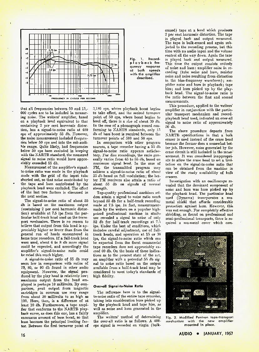
Fig. 1. Record- playback fre- quency response at both speeds with the amplifier
described.
that all frequencies between 50 and 15,- 000 cycles are to be included in measur- ing noise. The writers' amplifier, based on a playback level equivalent to that containing 2 per cent harmonic distor- tion, has a signal-to-noise ratio at 400 cps of approximately 55 db. However, the noise measurement included frequen- cies below 50 cps and into the sub-audi- We range. Quite likely, had frequencies below 50 cps been excluded in keeping with the NARTB standard, the measured signal to noise ratio would have appre- ciably exceeded 55 db.
Measurement of the amplifier's signal- to-noise ratio was made in the playback mode with the grid of the input tube shorted out, so that noise contributed by the tape and hum contributed by the playback head were excluded. The effect of the last two factors is discussed in the next section.
The signal-to-noise ratio of about 55 db is based on the maximum output (containing 2 per cent harmonic distor- tion) available at 7.5 ips from the par- ticular half-track head used on the trans- port mechanism. There is no reason to believe that output from this head is ap- preciably higher or lower than from the general run of heads encountered in home tape recorders. If a full-track head were used, about 6 to 8 db more signal could be expected, and accordingly the amplifier's signal-to-noise ratio could be rated this much higher.
A signal-to-noise ratio of 55 db may seem low in comparison with ratios of 70, 80, or 90 db found in other audio equipment. However, the signal pro- duced by the play head is relatively low; maximum output from the head em- ployed is perhaps 10 millivolts. By com- parison, peak output from magnetic cartridges in common use may range from about 30 millivolts to as high as 100. Here, then, is a difference of at least 10 db. Furthermore, a tape ampl- fier that conforms to the NARTB play- back curve, as does this one, has a fairly enormous amount of bass boost, so that hum becomes the principal limiting fac- tor. Between the first turnover point of
3,180 cps, where playback boost begins to take effect, and the second turnover point of 50 cps, where boost begins to level off, there is a rise of about 30 db. In the case of a phonograph record con- forming to NARTB standards, only 15 db of bass boost is required between the turnover points of 500 and 50 cps.
In comparison with other program sources, a tape recorder having a 55 db signal-to-noise ratio appears satisfac- tory. For disc recordings, the ratio gen- erally varies from 45 to 55 db, based on maximum signal level. In the case of FM, the transmitted program may achieve a signal-to-noise ratio of about 55 db based on full modulation; the bet- ter FM receivers also attain a ratio of about 55 db on signals of normal strength.
Top-quality professional machines sel- dom attain a signal to noise ratio much beyond 55 db for a half-track recording made at 7.5 ips. In fact, measurements made by the writers on a popular high- priced professional machine in studio use revealed a signal to noise of only 52 db for half-track recordings at 7.5 ips. Under the best of conditions, which includes careful adjustment, use of full- track heads, and operation at 15 or 30 ips, the signal-to-noise ratio which can be expected from the finest commercial tape recorders does not appreciably ex- ceed 60 db. On the basis of these indica- tions as to the present state of the art, an amplifier with a potential 55 db sig- nal to noise ratio based on the output available from a half-track head may be considered to meet today's standards of high fidelity.
Over-all Signal-to-Noise Ratio
The reference here is to the signal- to-noise ratio of the entire tape recorder, taking into consideration hum picked up by the playback head and tape hiss, as well as noise and hum generated in the amplifier.
The writers' method of determining the over-all ratio is as follows. A 400- cps signal is recorded on virgin (bulk-
erased) tape at a level which produces 2 per cent harmonic distortion. The tape is played back and output measured. The tape is bulk-erased and again sub- jected to the recording process, but this time with no audio input and the volume control all the way down. Again the taoe is played back and output measured. This time the output consists entirely of noise and hum: amplifier noise in re- cording (tube noise and hum, resistor noise and noise resulting from distortion in the bias-frequency waveform); am- plifier noise and hum in playback; tape hiss; and hum picked up by the play- back head. The signal-to-noise ratio is the ratio between the first and second measurements.
This procedure, applied to the writers" amplifier in conjunction with the partic- ular transport mechanism and record- playback head used, indicated an over-all signal to noise ratio of approximately 50 db.
The above procedure departs from NARTB specifications in that a bulk eraser is used instead of the erase head because the former does a somewhat bet- ter job. However, noise generated by the erase circuit is still included in the meas- urement. It was considered inappropri- ate to allow the erase head to set a limi- tation on the signal-to-noise ratio that can be obtained from the machine in view of the ready availability of bulk erasers.
Investigation with an oscilloscope re- vealed that the dominant component of noise and hum was hum picked up by the playback head. The particular head used (Dynamu) incorporates a mu- metal shield that affords considerable protection against hum. However, this was not enough. For completely effective shielding, as found on professional and semi-professional transports, there is re- quired a mu-metal cover which com-
Fig. 2. Modified Pentron tape-transport mechanism with the new amplifier
mounted in place.
[mvffl UGHTj
liWOTOH SWITCH)] [KQUAIIZATION CHANOE)|
16 AUDIO • jANUARY, 1957
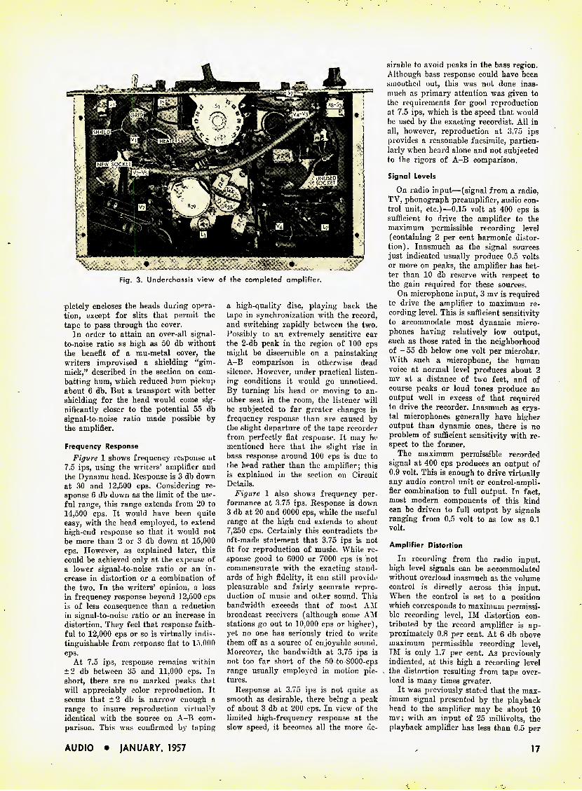
Fig. 3. Underchassis view of the completed amplifier.
pletely encloses the heads during opera- tion, except for slits that permit the tape to pass through the cover.
In order to attain an over-all signal- to-noise ratio as high as 50 db without the benefit of a mu-metal cover, the writers improvised a shielding "gim- mick," described in the section on com- batting hum, which reduced hum pickup about 6 db. But a transport with better shielding for the head would come sig- nificantly closer to the potential 55 db signal-to-noise ratio made possible by the amplifier.
Frequency Response Figure 1 shows frequency response at
7.5 ips, using the writers' amplifier and the Dynamu head. Response is 3 db down at 30 and 12,500 cps. Considering re- sponse 6 db down as the limit of the use- ful range, this range extends from 20 to 14,500 cps. It would have been quite easy, with the head employed, to extend high-end response so that it would not be more than 2 or 3 db down at 15,000 cps. However, as explained later, this could be achieved only at the expense of a lower signal-to-noise ratio or an in- crease in distortion or a combination of the two. In the writers' opinion, a loss in frequency response beyond 12,500 cps is of less consequence than a reduction in signal-to-noise ratio or an increase in distortion. They feel that response faith- ful to 12,000 cps or so is virtually indis- tinguishable from response flat to 15,000 cps.
At 7.5 ips, response remains within ± 2 db between 35 and 11,000 cps. In short, there are no marked peaks that will appreciably color reproduction. It seems that ±2 db is narrow enough a range to insure reproduction virtually identical with the source on A-B com- parison. This was confirmed by taping
a high-quality disc, playing back the tape in synchronization with the record, and switching rapidly between the two. Possibly to an extremely sensitive ear the 2-db peak in the region of 100 cps might be discernible on a painstaking A-B comparison in otherwise dead silence. However, under practical listen- ing conditions it would go unnoticed. By turning his head or moving to an- other seat in the room, the listener will be subjected to far greater changes in frequency response than are caused by the slight departure of the tape recorder from perfectly flat response. It may be mentioned here that the slight rise in bass response around 100 cps is due to fhe head rather than the amplifier; this is explained in the section on Circuit Details.
Figure 1 also shows frequency per- formance at 3.75 ips. Response is down 3 db at 20 and 6000 cps, while the useful range at the high end extends to about 7,250 cps. Certainly this contradicts the oft-made statement that 3.75 ips is not fit for reproduction of music. While re- sponse good to 6000 or 7000 cps is not commensurate with the exacting stand- ards of high fidelity, it can still provide pleasurable and fairly accurate repro- duction of music and other sound. This bandwidth exceeds that of most AM broadcast receivers (although some AM stations go out to 10,000 cps or higher), yet no one has seriously tried to write them off as a source of enjoyable sound. Moreover, the bandwidth at 3.75 ips is not too far short of the 50-to-8000-eps range usually employed in motion pic- tures.
Response at 3.75 ips is not quite as smooth as desirable, there being a peak of about 3 db at 200 cps. In view of the limited high-frequency response at the slow speed, it becomes all the more de-
sirable to avoid peaks in the bass region. Although bass response could have been smoothed out, this was not done inas- much as primary attention was given to the requirements for good reproduction at 7.5 ips, which is the speed that would be used by the exacting recordist. All in all, however, reproduction at 3.75 ips provides a reasonable facsimile, particu- larly when heard alone and not subjected to the rigors of A-B comparison.
Signal Levels
On radio input—(signal from a radio, TV, phonograph preamplifier, audio con- trol unit, etc.)—0.15 volt at 400 cps is sufficient to drive the amplifier to the maximum permissible recording level (containing 2 per cent harmonic distor- tion). Inasmuch as the signal sources just indicated usually produce 0.5 volts or more on peaks, the amplifier has bet- ter than 10 db reserve with respect to the gain required for these sources.
On microphone input, 3 mv is required to drive the amplifier to maximum re- cording level. This is sufficient sensitivity to accommodate most dynamic micro- phones having relatively low output, such as those rated in the neighborhood of - 55 db below one volt per microbar. With such a microphone, the human voice at normal level produces about 2 mv at a distance of two feet, and of course peaks or loud tones produce an output well in excess of that required to drive the recorder. Inasmuch as crys- tal microphones generally have higher output than dynamic ones, there is no problem of sufficient sensitivity with re- spect to the former.
The maximum permissible recorded signal at 400 cps produces an output of 0.9 volt. This is enough to drive virtually any audio control unit or control-ampli- fier combination to full output. In fact, most modern components of this kind can be driven to full output by signals ranging from 0.5 volt to as low as 0.1 volt.
Amplifier Distortion
In recording from the radio input, high level signals can be accommodated without overload inasmuch as the volume control is directly across this input. When the control is set to a position which corresponds to maximum permissi- ble recording level, IM distortion con- tributed by the record amplifier is ap- proximately 0.8 per cent. At 6 db above maximum permissible recording level, IM is only 1.7 per cent. As previously indicated, at this high a recording level the distortion resulting from tape over- load is many times greater.
It was previously stated that the max- imum signal presented by the playback head to the amplifier may be about 10 mv; with an input of 25 millivolts, the playback amplifier has less than 0.5 per
AUDIO • JANUARY, 1957 17
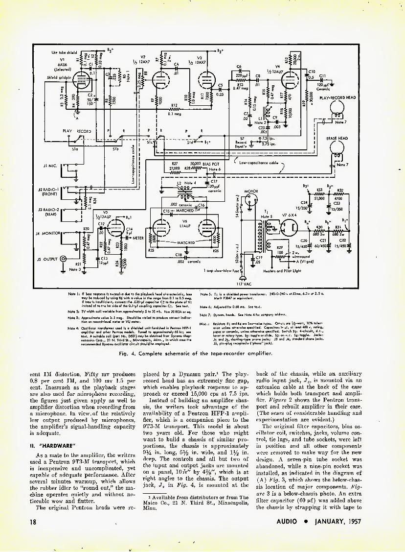
Note 1; If boil response Is excessive due »o the playback head characteristic, bass Note 5: Tj is a shielded power transformer. 240-0-240 v at50ma, 6.3v at 2.5 a. may be reduced by using R6 with a value in the range from 0.1 to 0.5 meg. Merit P3047 or equivalent. If bass is insufficient, connect the .035-pf capacitor C2 to the plate of VI instead of to the far side of the 0.1-pf coupling capacitor C]. See text. Note 6: Adjusted for 0.68 ma. See text.
Note 2: TV width coil variable from approximately 5 to 35 mh. Ram 20)R3A or eq. Note 7: Dynamu heads. See Note 4 for company address. Note 3; Approximate value is 5 meg. Should be varied to produce correct indica- tion on record-level meter or VU meter. ... _ . _ k inai »„u,_ Misc.: Resistors R] and R4 are low-noise types. Others are '/^-watt, 10% toler- Note 4: OsciHator transformer used is a shielded unit furnished in Pentron HFP-1 ance unless otherwise specified. Capacitors in pf, at least 400 v. rating,
amplifier and other Pentron models. Tuned to approximately 65 Itc; see paper or ceramic, unless otherwise specified. Switch Sj: 4-circuit, d.t., text. A suitable coil (part No. D501) may be obtained from Dynamu Mag- lever or rotary type. $2: toggle or slide. S3: on v.c. S4: toggle. Jacks: netronics Corp., 21 N. Third St., Minneapolis, Minn., in which case the -M and J2, shorting-type phone jocks; J3 and J4, standard phone jacks, recommended Dynamu oscillator circuit should be employed. J5, pin-plug receptacle ("phono" jack).
Fig. 4. Complete schematic of the tape-recorder amplifier.
cent IM distortion. Fifty mv produces 0.8 per cent IM, and 100 mv 1.5 per cent. Inasmuch as the playback stages are also used for microphone recording, the figures just given apply as well to amplifier distortion when recording from a microphone. In view of the relatively low output produced by microphones, the amplifier's signal-handling capacity is adequate.
II. "HARDWARE"
As a mate to the amplifier, the writers used a Pentron 9T3-M transport, which is inexpensive and uncomplicated, yet capable of adequate performance. After several minutes warmup, which allows the rubber idler to "round out," the ma- chine operates quietly and without no- ticeable wow and flutter.
The original Pentron heads were re-
placed by a Dynamu pair.1 The play- record head has an extremely fine gap, which enables playback response to ap- proach or exceed 15,000 cps at 7.5 ips.
Instead of building an amplifier chas- sis, the writers took advantage of the availability of a Pentron HFP-1 ampli- fier, which is a companion piece to the 9T3-M transport. This model is about two years old. For those who might want to build a chassis of similar pro- portions, the chassis is approximately 91/i in. long, 5^2 in- wide, and l1/^ in. deep. The controls and all but two of the input and output jacks are mounted on a panel, 10 A" by 4%", which is at right angles to the chassis. The output jack, Jj in Fig. 4, is mounted at the
1 Available from distributors or from The Maico Co., 21 N. Third St., Minneapolis, Minn.
back of the chassis, while an auxiliary z'adio input jack, J3. is mounted via an extension cable at the back of the case which holds both transport and ampli- fier. Figure 2 shows the Pentron trans- port and rebuilt amplifier in their case. (The scars of considerable handling and experimentation are evident.)
The original filter capacitors, bias os- cillator coil, switches, jacks, volume con- trol, tie lugs, and tube sockets, were left in position and all other components were removed to make way for the new design. A seven-pin tube socket was abandoned, while a nine-pin socket was installed, as indicated in the diagram of (A) Fig. 3, which shows the below-chas- sis location of major components. Fig- ure 3 is a below-chassis photo. An extra filter capacitor (60 |xf) was added above the chassis by strapping it with tape to
18 AUDIO • JANUARY, 1957

VOLUME CONTROL
Fig. 5. Functions of the amplifier in the record mode.
one of the original capacitor cans. The Pentron IlFP-l originally came
with an inexpensive meter (including rectifier) to show recording level. In or- der to maintain a high signal-to-noise ratio without overstepping into the area of extreme distortion, it is all-important to have as reliable an indication of re- cording level as possible. This means not only that the meter should have wide frequency response but that it should also possess such characteristics as brief time lag, minimum overshoot, and ability to withstand considerable overload. Al- though economy of construction was con- sidered important, it was nevertheless felt that the primary goal of quality justifies splurging on a professional type indicator. This can be either a VU meter or a recording level meter. The latter was used inasmuch as one happened to be on hand in a piece of war surplus equipment.
III. GENERAL CIRCUIT DESCRIPTION
Figure 4 is the schematic of the am- plifier. The five tubes and associated com- ponents have to perform a considerable number of functions: they provide gain, recording equalization, playback equal- ization, recording bias, erase current, driving power for the recording-level meter, and the necessary power supply. To clarify operation of the amplifier. Figs. 5 and 6 respectively present sim- plified block diagrams of the record and playback modes.
Record Mode
The input signal from a microphone goes to V, for amplification and then through the volume control to F2. Higher level signals (as from a tuner), which are fed into the radio input jack.
bypass I', and go to V2 via the volume control. V2 amplifies the signal and feeds it to cathode follower T%. The low out- put impedance of a cathode follower is desirable here inasmuch as Vs feeds the signal to three points, which have rela- tively high impedance and therefore do not load down the signal. These points are: (1) the monitor jack; (2) Vs, which drives the recording-level indica- tor; (3) the equalization and driving stages preceding the record head (this head is also used for playback).
From V, the signal goes through a combined treble and bass boost network and into Vi, which drives the record head. Associated with V4) in the form of a cathode-resistor bypass, is a tuned treble-boost circuit.
As the audio signal goes from Vi to the record head, a "bias" current of supersonic frequency is added, which is required in order to reduce distortion and increases the amount of signal re- corded on the tape to an adequate level. Ve is an oscillator producing the high-
PLAYBACK HEAD
©B^ AND FILAMENT SUPPLY
frequency current, only a small portion of which is used for bias. Most of this current is used to drive the erase head, permitting erasure of previously re- corded signals.
Finally there is the transformer-oper- ated power supply stage, using F- as a rectifier for B+, and furnishing 6.3 v. a.c. heater voltage for all tubes.
Play Mode
As shown in Fig. 6, the play mode is much the simpler of the two. The signal from the playback head (also used for record) is amplified by V,, passes through a bass boost losses network pro- viding NARTB equalization, and is fur- ther amplified by F,. The signal is fed to Vs and from there to the output jack, J5. Since F, is a cathode follower and therefore has low source impedance, as pointed out above, frequency response is unaffected by the large amount of shunt capacitance in a relatively long cable run from the tape recorder to a power amplifier; using low-capacitance cable (say 25 Wifd per foot), runs in excess of 100 feet are feasible.
The signal from V3 is also fed to V5, which drives the recording level meter. Thus in playback it may be ascertained whether a tape, possibly made on another machine, has been recorded at a level that is obviously too high, obviously too low, or about right. The power supply is as previously described.
IV. CIRCUIT DETAILS
In this section detailed attention is accorded to the following: inputs and outputs; equalization, the record driv- ing stage; the bias oscillator; the record- level indicator; play-record switching; use of low noise resistors; Miller effect; direct coupling (tried but not used).
Inputs and Outputs
As Fig. 4 shows, the signal from F, does not go directly^ to the volume con- trol but first passes through the shorting and "hot" terminals of the radio input
{Continued on page 63)
BASS BOOST
(NARTB) > OUTPUT
JACK
RECORD-LEVEL METER
Fig. 6. Functions of the amplifier in the playback mode.
AUDIO • JANUARY, 1957 19
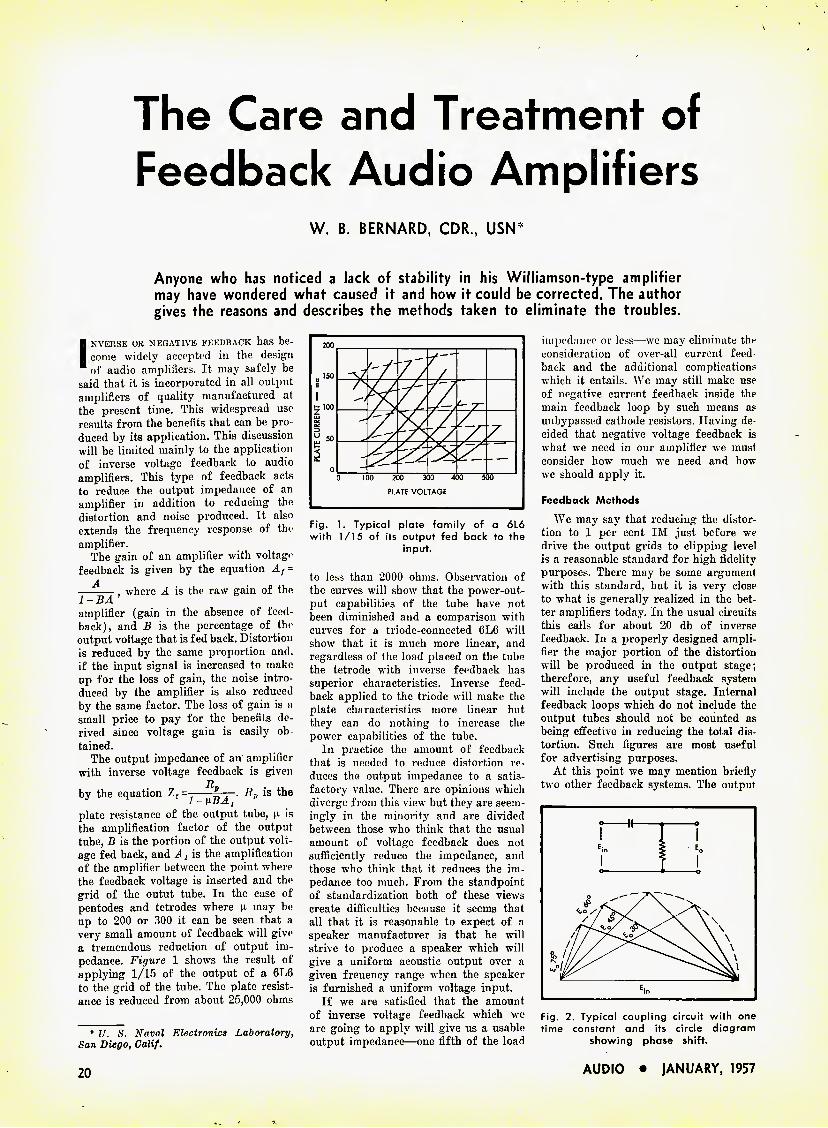
The Care and Treatment of
Feedback Audio Amplifiers
W. B. BERNARD, CDR., USNP
Anyone who has noticed a lack of stability in his Williamson-type amplifier may have wondered what caused it and how it could be corrected. The author gives the reasons and describes the methods taken to eliminate the troubles.
INVERSE OB NEGATIVE FEEDBACK has be- come widely accepted in the design of audio amplifiers. It may safely be
said that it is incorporated in all output amplifiers of quality manufactured at the present time. This widespread use results from the benefits that can be pro- duced by its application. This discussion will be limited mainly to the application of inverse voltage feedback to audio amplifiers. This type of feedback acts to reduce the output impedance of an amplifier in addition to reducing the distortion and noise produced. It also extends the frequency response of th«' amplifier.
The gain of an amplifier with voltage feedback is given by the equation Af -
A , where is the raw gain of the L-BA' amplifier (gain in the absence of feed- back), and B is the percentage of the output voltage that is fed back. Distortion is reduced by the same proportion and. if the input signal is increased to make up for the loss of gain, the noise intro- duced by the amplifier is also reduced by the same factor. The loss of gain is a small price to pay for the benefits de- rived since voltage gain is easily ob tained.
The output impedance of an amplifier with inverse voltage feedback is given
It by the equation Zf =- 7ri~- ^]>'s t-he
plate resistance of the output tube, n is the amplification factor of the output tube, B is the portion of the output volt- age fed back, and A, is the amplification of the amplifier between the point where the feedback voltage is inserted and the grid of the outut tube. In the case of pentodes and tetrodes where u may be up to 200 or 300 it can be seen that a very small amount of feedback will give a tremendous reduction of output im- pedance. Figure 1 shows the result of applying 1/15 of the output of a 6L6 to the grid of the tube. The plate resist- ance is reduced from about 25,000 ohms
* V. S. Naval Electronics Laboratory, San Diego, Calif.
Fig. 1. Typical plate family of a 6L6 with 1/15 of its output fed back to the
Input.
to less than 2000 ohms. Observation of the curves will show that the power-out- put capabilities of the tube have not been diminished and a comparison with curves for a triode-connected 6L6 will show that it is much more linear, and regardless of the load placed on the tube the tetrode with inverse feedback has superior characteristics. Inverse feed- back applied to the triode will make the plate characteristics more linear but they can do nothing to increase the power capabilities of the tube.
In practice the amount of feedback that is needed to reduce distortion re- duces the output impedance to a satis- factory value. There are opinions which diverge from this view but they are seem- ingly in the minority and are divided between those who think that the usual amount of voltage feedback does not sufficiently reduce the impedance, and those who think that it reduces the im- pedance too much. From the standpoint of standardization both of these views create difficulties because it seems that all that it is reasonable to expect of a speaker manufacturer is that he will strive to produce a speaker which will give a uniform acoustic output over a given freuency range when the speaker is furnished a uniform voltage input.
If we are satisfied that the amount of inverse voltage feedback which we are going to apply will give us a usable output impedance—one fifth of the load
impedance or less—we may eliminate the consideration of over-all current feed back and the additional complication? which it entails. We may still make use of negative current feedback inside the main feedback loop by such means as unbypassed cathode resistors. Having de- cided that negative voltage feedback is what we need in our amplifier we must consider how much we need and how we should apply it.
Feedback Methods
We may say that reducing the distor- tion to 1 per cent IM just before we drive the output grids to clipping level h a reasonable standard for high fidelity purposes. There may be some argument with this standard, but it is very close to what is generally realized in the bet- ter amplifiers today. In the usual circuits this calls for about 20 db of inverse feedback. In a properly designed ampli- fier the major portion of the distortion will be produced in the output stage; therefore, any useful feedback system will include the output stage. Internal feedback loops which do not include the output tubes should not be counted as being effective in reducing the total dis- tortion. Such figures are most useful for advertising purposes.
At this point we may mention briefly two other feedback systems. The output
Fig. 2. Typical coupling circuit with one time constant and its circle diagram
showing phase shift.
20 AUDIO • JANUARY, 1957
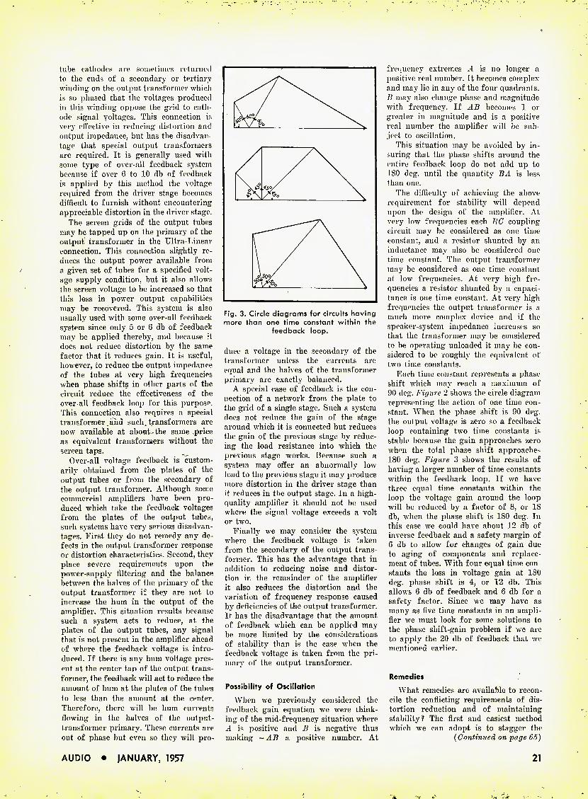
tube cathodes are sometiines returned to the ends of a secondary or tertiary winding on the output transformer which is so phased that the voltages produced in this winding oppose the grid to cath- ode signal voltages. This connection ir. very effective in reducing distortion and output impedance, but has the disadvan- tage that special output transformers are required. It is generally used with some type of over-all feedback system because if over 6 to 10 db of feedback is applied by this method the voltage required from the driver stage becomes difficult to furnish without encountering appreciable distortion in the driver stage.
The screen grids of the output tubes may be tapped up on the primary of the output transformer in the Ultra-Linear connection. This connection slightly re- duces the output power available from a given set of tubes for a specified volt- age supply condition, but it also allows the screen voltage to be increased so that this loss in power output capabilities may be recovered. This system is also usually used with some over-all feedback system since only 5 or G db of feedback may be applied thereby, and because it does not reduce distortion by the same factor that it reduces gain. It is useful, however, to reduce the output impedance of the tubes at very high frequencies when phase shifts in other parts of the circuit reduce the effectiveness of the over-all feedback loop for this purpose, This connection also requires a special transformer aiid such transformers are now available at about the same price as equivalent transformers without the screen taps.
Over-all voltage feedback is custom- arily obtained from the plates of the output tubes or from the secondary of the output transformer. Although some commercial amplifiers have been pro- duced which take the feedback voltages from the plates of the output tubes, such systems have very serious disadvan- tages. First they do not remedy any de- fects in the output transformer response or distortion characteristics. Second, they place severe requirements upon the power-supply filtering and the balance between the halves of the primary of the output transformer if they are not to increase the hum in the output of the amplifier. This situation results because such a system acts to reduce, at the plates of the output tubes, any signal that is not present in the amplifier ahead of where the feedback voltage is intro- duced. If there is any hum voltage pres- ent at the center tap of the output trans- former, the feedback will act to reduce the amount of hum at the plates of the tubes to less than the amount at the center. Therefore, there will be hum currents flowing in the halves of the output- transformer primary. These currents are out of phase but even so they will pro-
Fig. 3. Circle diagrams for circuits having more than one time constant within the
feedback loop.
duce a voltage in the secondary of the transformer unless the currents are equal and the halves of the transformer primary are exactly balanced.
A special case of feedback is the con- nection of a network from the plate to the grid of a single stage. Such a system does not reduce the gain of the stage around which it is connected but reduces the gain of the previous stage by reduc- ing the load resistance into which the previous stage works. Because such a system may offer an abnormally low load to the previous stage it may produce more distortion in the driver stage than it reduces in the output stage. In a high- quality amplifier it should not be used where the signal voltage exceeds a volt or two.
Finally we may consider the system where the feedback voltage is taken from the secondary of the output trans- former. This has the advantage that in addition to reducing noise and distor- tion in the remainder of the amplifier it also reduces the distortion and the variation of frequency response caused by deficiencies of the output transformer. It has the disadvantage that the amount of feedback which can be applied may be more limited by the considerations of stability than is the case when the feedback voltage is taken from the pri- mary of the output transformer.
Possibility of Oscillation
When we previously considered the feedback gain equation we were think- ing of the mid-frequency situation where .4 is positive and B is negative thus making - AB a positive number. At
frequency extremes -l is no longer a positive real number. It becomes complex and may lie in any of the four quadrants. B may also change phase and magnitude with frequency. If AB becomes 1 or greater in magnitude and is a positive real number the amplifier will be sub- ject to oscillation.
This situation may be avoided by in- suring that the phase shifts around the entire feedback loop do not add up to ISO deg. until the quantity BA is less than one.
The difficulty of achieving the above requirement for stability will depend upon the design of the amplifier. At very low frequencies each EG coupling circuit may be considered as one time constant, and a resistor shunted by an inductance may also be considered one time constant. The output transformer may be considered as one time constant at low frequencies. At very high fre- quencies a resistor shunted by a capaci- tance is one time constant. At very high frequencies the output transformer is a much more complex device and if the speaker-system impedance increases so that the transformer may be considered to be operating unloaded it may be con- sidered to be roughly the equivalent of two time constants.
Each time constant represents a phase shift which may reach a maximum of 90 deg. Figure 2 shows the circle diagram representing the action of one time con- stant. When the phase shift is 90 deg. the output voltage is zero so a feedback loop containing two time constants is stable because the gain approaches zero when the total phase shift approaches 180 deg. Figure 3 shows the results of having a larger number of time constants within the feedback loop. Ff we have three equal time constants within the loop the voltage gain around the loop will be reduced by a factor of 8, or 18 db, when the phase shift is 180 deg. In this case wTe could have about 12 db of inverse feedback and a safety margin of 6 db to allow for changes of gain due to aging of components and replace- ment of tubes. With four equal time con- stants the loss in voltage gain at 180 deg. phase shift is 4, or 12 db. This allows 6 db of feedback and 6 db for a safety factor. Since we may have as many as five time constants in an ampli- fier we must look for some solutions to the phase shift-gain problem if we are to apply the 20 db of feedback that we mentioned earlier.
Remedies
What remedies are available to recon- cile the conflicting requirements of dis- tortion reduction and of maintaining stability? The first and easiest method which we can adopt is to stagger the
{Continued on page 65)
AUDIO • JANUARY, 1957 21

Acoustical and Electrical Considerations
in Symphony Orchestra Reproduction
WALTER T. SELSTED* and ROSS H. SNYDER*
Results of a full-scale experiment with three channel stereophonic recording and repro- ducing apparatus of advanced characteristic? to determine if an orchestra can be repro- duced with sufficient realism as to be essentially indistinguishable from the original.
Fig. 1. The San Francisco Symphony Orchestra during a rehearsal prior to the experi- ment described. Number being played is "Rhapsodic Variations for Tape Recorder and Orchestra," with Dr. Ussachevsky at the console of the Ampex and Enrique
Jorda on the podium. Note placement of loudspeakers.
WITH THE COOPERATION of COTlductOl' Enrique Jorda, the members of the San Francisco Symphony Or-
chestra, and the San Francisco Sym- phony Association, an experiment wns set up, in the San Francisco War Me- morial Opera House, to find if, with presently available techniques, repro- duction of the full Symphony Orchestra can be achieved with sufficient fidelity that no appreciable portion of a larg:' audience could distinguish between the live original and the reproduced sound. Preliminary recording experiments were made during the week preceding the public performance.
While a portion of the public concert was devoted to pure entertainment, in order that the audience might be in as nearly a normal frame of reference as possible, two sections of the concert were performed under controlled conditions, in order that reasonable evaluation might be made of the results in question.
It is not always the custom of this orchestra to tune on stage, so it was possible to prepare the orchestral in- struments before the entry of the per- formers in such a way that performance might be simulated, at the very begin- ning of the program, without the pro- duction of significant sound from the in- struments themselves, and without neces- sarily arousing the audience's suspi- cions. The string instruments, in par- ticular, needed carefully considered treatment, since the musicians could not be expected to simulate playing without detection, while poising bows at all times off the strings. This was accomplished by wrapping the strings of each instrument with transparent cellulose film. The first selection on the program was the ()ver- ture to Mozart's "'The Marriage of Fig- aro." The entire composition, less than five minutes in length, had been recorded in rehearsal. The orchestral pantomime, likewise, had been skillfully perfected by Maestro Jorda and the musicians prior to the public performance. So far as the audience was concerned, then, the program opened in the normal manner,
* Ampcx Corporal ion. 934 Charier St., Eedwood City, Calif.
the conductor taking his place as usual, rapping his music stand, and opening the program in a usual way. Unconcealed in the midst of the orchestra were three theatre-type loudspeaker systems, from which the music was actually played. "Spotters" were dispersed throughout the audience of approximately 2,500 peo- ple, to note reactions. Toward the end of the overture, on cue from the con- ductor, the musicians laid down their in- struments, while the music continued unchanged. Spotlights picked out the loudspeakers, to indicate clearly what was then going on. At the end of the overture, a narrator explained to the audience that the deception which had just been practiced would not again be repeated, and that it was with the reali- zation that a sophisticated audience could probably not be so deceived unless the exp riinent were presented without warning, that this experiment had been placed at the very opening of the eve- ning's program. The explanation was.
however, ambiguous as to whether the orchestra had played any part of the
Fig. 2. Close-up of the recorder rack and control position with the three-channel Ampex and its associated amplifiers. At the left of the rack are the power ampli-
fiers for the three speaker systems.
22 AUDIO • JANUARY, 1957
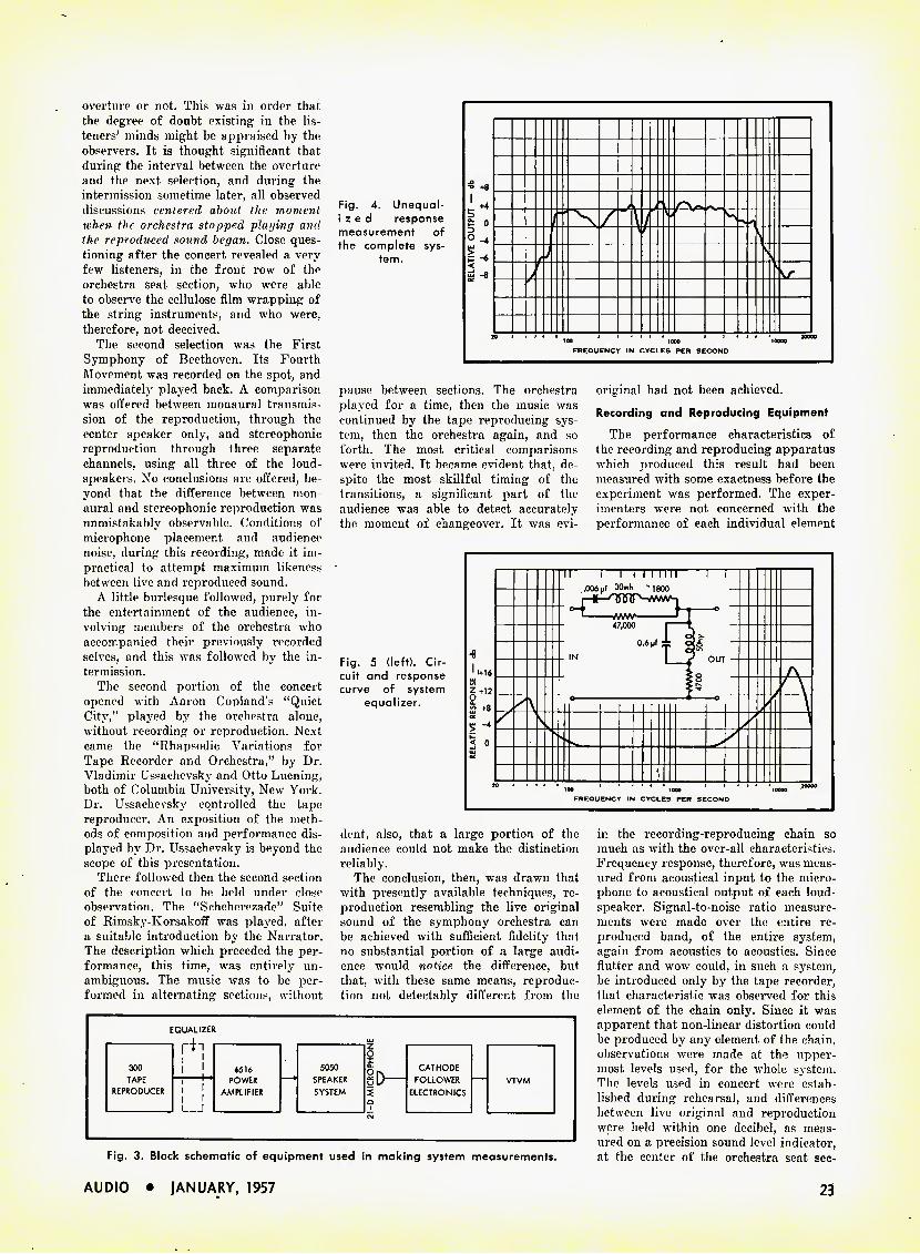
overture or not. This was in order that the degree of doubt existing in the lis- teners' minds might be appraised by the observers. It is thought significant that during the interval between the overture and the next selection, and during the intermission sometime later, all observed discussions centered about the moment when the orchestra stopped playing and the reproduced sound began. Close ques- tioning after the concert revealed a very few listeners, in the front row of the orchestra seat section, who were able to observe the cellulose film wrapping of the string instruments, and who were, therefore, not deceived.
The second selection was the First Symphony of Beethoven. Its Fourth Movement was recorded on the spot, and immediately played back. A comparison was offered between monaural transmis- sion of the reproduction, through the center speaker only, and stereophonic reproduction through three separate channels, using all three of the loud- speakers. No conclusions are offered, be- yond that the difference between mon- aural and stereophonic reproduction was unmistakably observable. Conditions of microphone placement and audience noise, during this recording, made it im- practical to attempt maximum likeness between live and reproduced sound.
A little burlesque followed, purely for the entertainment of the audience, in- volving members of the orchestra who accompanied their previously recorded selves, and this was followed by the in- termission.
The second portion of the concert opened with Aaron Copland's "Quiet City," played by the orchestra alone, without recording or reproduction. Next came the "Rhapsodic Variations for Tape Recorder and Orchestra," by Dr. Vladimir Ussachevsky and Otto Luening, both of Columbia University, New York. Dr. Ussachevsky controlled the tape reproducer. An exposition of the meth- ods of composition and performance dis- played by Dr. Ussachevsky is beyond the scope of this presentation.
There followed then the second section of the concert to be held under close observation. The "Scheherezade" Suite of Rimsky-Korsakoff was played, after a suitable introduction by the Narrator. The description which preceded the per- formance, this time, was entirely un- ambiguous. The music was to be per- formed in alternating sections, without
Fig. 4. Unequal- i z e d response measurement of the complete sys-
tem.
-o +8
t 0 O -4 ^ . / ) \
> r
V
» 1000 FREQUENCY IN CYCLES PER SECOND
pause between sections. The orchestra played for a time, then the music was continued by the tape reproducing sys- tem, then the orchestra again, and so forth. The most critical comparisons were invited. It became evident that, de- spite the most skillful timing of the transitions, a significant part of the audience was able to detect accurately the moment of changeover. It was evi-
original had not been achieved.
Recording and Reproducing Equipment
The performance characteristics of the recording and reproducing apparatus which produced this result had been measured with some exactness before the experiment was performed. The exper- imenters were not concerned with the performance of each individual element
Fig. 5 (left). Cir- cuit and response curve of system
equalizer.
^'+16
'-n +-8 LU "
< o
1 I I I I I I I I I I .006 pf 30mh 1800
l mw M 0
47,000 1 0.6 Mf
» lOOO FREQUENCY IN CYCLES PER SECOND
dent, also, that a large portion of the audience could not make the distinction reliably.
The conclusion, then, was drawn that with presently available techniques, re- production resembling the live original sound of the symphony orchestra can be achieved with sufficient fidelity that no substantial portion of a large audi- ence would notice the difference, but that, with these same means, reproduc- tion not detectably different from the
EQUALIZER
!'I 300 l i 6516 TAPE 1 POWER
REPRODUCER i I i i AMPLIFIER L J
5050 SPEAKER SYSTEM
D— CATHODE
FOLLOWER ELECTRONICS
Fig. 3. Block schematic of equipment used in making system measurements.
in the recording-reproducing chain so much as with the over-all characteristics. Frequency response, therefore, was meas- ured from acoustical input to the micro- phone to acoustical output of each loud- speaker. Signal-to-noise ratio measure- ments were made over the entire re- produced band, of the entire system, again from acoustics to acoustics. Since flutter and wow could, in such a system, be introduced only by the tape recorder, that characteristic was observed for this element of the chain only. Since it was apparent that non-linear distortion could be produced by any element of the chain, observations were made at the upper- most levels used, for the whole system. The levels used in concert were estab- lished during rehearsal, and differences between live original and reproduction were held within one decibel, as meas- ured on a precision sound level indicator, at the center of the orchestra seat sec-
AUDIO • JANUARY, 1957 23
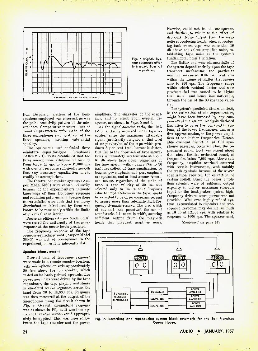
Fig. 6 (right). Sys- tem response after introduction of
equalizer.
tion. Dispersion pattern of the loud- speakers employed was observed, as was the polar sensitivity pattern of the mic- rophones. Comparative measurements of essential parameters were made of the three microphones employed, and of the three speakers, insuring substantial equality.
The equipment used included three miniature capacitor-type microphones (Altec 21-D). Tests established that the three microphones exhibited uniformity from below 40 cps to above 12,000 cps with over-all response sufficiently smooth that any necessary equalization might readily be accomplished.
The theatre loudspeaker systems (Am- pex Model 5050) were chosen primarily because of the experimenter's intimate knowledge of their frequency response and radiation patterns, and because these characteristics were such that frequency discrimination introduced by them was known to be reasonably within the limits of practical equalization.
Power amplifiers (Ampex Model 6516) were tested for uniformity of frequency response at the power levels predicted.
The frequency response of the tape recorder-reproducer used (Ampex Model 300-3) was not of consequence to the experiment, since it is inherently flat.
Speaker Measurement
Over-all tests of frequency response were made in a remote country location, with microphone on axis approximately 20 feet above the loudspeaker, which rested on its back, pointed upwards. The power amplifiers were driven by the tape reproducer, the tape playing multitones in one-third octave segments across the band from 30 to 15,000 cps. Response was then measured at the output of the microphones using the circuit shown in Fig. 3. Over-all unequalized response was as shown in Fig. 4. It was then ap- parent that equalization could appropri- ately be applied. This was inserted be- tween the tape recorder and the power
amplifiers. The character of the equal- izer, and its effect upon over-all re- sponse, are shown in Figs. 5 and 6.
As for signal-to-noise ratio, the limi- tation certainly occurred in the tape re- corder, since the maximum attainable signal (arbitrarily assigned as that level of magnetisation of the tape which pro- duces 3 per cent total harmonic distor- tion due to the approach of tape satura- tion) is ultimately establishable at about 65 db above tape noise, regardless of the tape speed (within range to 30 ips), regardless of tape equalization, so long as pre-emphasis and post-emphasis are optimum, and at least among Ameri- can makes, regardless of the make of tape. A tape velocity of 30 ips was selected only to assure that dropouts (due to imperfections in the tape) could be expected to be of no consequence, and to assure more than adequate high-fre- quency dynamic reserve. The tape width of one-half inch permitted the use of soundtracks 0.1 inches in width, assuring sufficient output from the playback heads that playback amplifier noise.
likewise, could not be of consequence, and further to minimize the effect of dropouts. Noise output from the mag- netic reproducing heads, when reproduc- ing tank-erased tape, was more than 10 db above equivalent amplifier noise, es- tablishing tape noise as the system's fundamental noise limitation.
The flutter and wow characteristic of the system depend entirely upon the tape transport mechanism; the particular machine measured 0.04 per cent rms within the range of flutter frequencies zero to 200 cps. The frequency range within which residual flutter and wow products fell was caused to be higher than usual, and hence less noticeable, through the use of the 30 ips tape veloc- ity.
The system's predicted distortion limit, in the estimation of the experimenters, might have been imposed by any com- ponents of the system. Analysis disclosed limitation to be in the loudspeaker sys- tems, at the lower frequencies, and as a first approximation, in the power ampli- fiers at the higher frequencies. Detect- able overload distortion, in full sym- phonic passages, occurred when the re- produced sound level was raised about 6 db above the live orchestral sound, at frequencies below 7,000 cps. Above this frequency, amplifier overload occurred with certain instruments, with notably the crash cymbals, because of the severe equalization required for correction of system rolloff. Since the power ampli- fiers selected were of sufficient output capacity to deliver maximum tolerable input to the loudspeaker system high- frequency drivers, more power was not provided. With even highly refined sys- tems, accumulated loudspeaker and mic- rophone response may decline as much as 16 db at 12,000 cps, with relation to response at 1000 cps. The speaker used,
(Continued on page 06)
0 0 o1 0 0 0
EQUALIZER POWER
AMPLIFIER 3 CHANNEL RECORDER- EQUALIZER
POWER REPRODUCER AMPLIFIER
EQUALIZER POWER
AMPLIFIER
Fig. 7. Recording and reproducing system block schematic for the San Francisco Opera House.
24 AUDIO • JANUARY, 1957

More About Hum
HAROLD REED
After all of the obvious and usual means have been tried in an effort to eliminate a particularly troublesome case of hum, it may sometimes be found to be due to an unusual cause such as this.
Much has been written about hum in audio amplifiers. The author has sometimes thought, in some of his
writings, that hp had covered the subject quite thoroughly, only later to be en- countered by hum conditions in circuitry not presented before by the writer, nor found discussed in other articles. One such subtle condition will be considered in this article.
It is well known to audio amplifier constructors, that the input tube operat- ing with low signal levels—such as the first tube in a preamplifier—should have minimum heater to cathode leakage. This leakage is due to a current flow between heater and cathode, which elements arc separated by a special type of insulation.
There are numerous ways to ease or
For a number of years the author has been working with circuits which place the cathode near ground potential with- out the use of a bypass capacitor. This circuit is not familiar to most audio workers but recently it is being more widely employed. The arrangement is given in Fig. 2. Here it will be seen that the cathode is placed only 390 ohms above ground. To maintain the proper d.c. bias a 68,000-ohm resistor is connected from the cathode to the plate supply. The cir- cuit works and has been used many times. Because the experimenter will be seeing this circuit more often, and using it, the author brings to attention one case when conditions were not as expected and hum presented quite a problem.
The circuit of Fig. 2 was used in a
preamplifier circuit as had been done many times before. This time, however, hum level was extremely high when the a.c. power plug was connected to the power line one certain way, dropping to a reasonable value when the plug was "turned over." One unit displayed a 17- db variation in hum output. With most amplifiers there is a "best" way, from the standpoint of hum, to insert the a.c. plug, but rarely with a resultant varia- tion as great as 17 db.
The Cure
Many things were tried to eliminate the difficulty. It was definitely proved that the hum entered the grid of the input stage of the amplifier. All input leads were removed from the grid of
Fig. 1. Typical schematic of input stage of a high-gain amplifier with cathode resistor bypassed in the customary
fashion.
1—v 000 /—1 POWER ( = TRANSFORMER!
i _S_rEEL_CHASS|S
Fig. 2. Method of reducing cathode-to- ground impedance without the use of a
bypass capacitor.
eliminate objectionable hum in the am- plifier output due to this leakage. As they have been well covered in technical publications, they will not be enumerated here. One of the most effective, of course, is to' place the cathode as near to ground potential as possible. A large cathode bypass capacitor is normally used for this purpose.
A 20-nf capacitor at the power line fre- quency of 60 cps has a reactance of about 130 ohms. Figure 1 shows a common cir- cuit of a triode with the 20-nf capacitor placing the cathode 130 ohms above ground and the 3900 ohm resistor pro- viding a d.c. bias on the tube of 1.2 volts.
* 3917 Madison St., Hyattsville, Md.
AUDIO • JANUARY, 1957
Fig. 3. (A) shows the original wirirtg of a typical tape recorder with the a.c. line not being twisted throughout. (B) shows rearrangement which eliminated a tricky
case of hum.
this input stage and a 0.47-meg resistor placed from the grid to ground. All a.c. wiring except filament leads was at least 10 inches from the input tube. Fila- ments were then supplied from a 6-volt battery which reduced the hum variation by only 5 db. This then, was not a simple matter of heater-cathode leakage at the a.c. power frequency. Nothing helped except balancing out the hum with a hum bucking potentiometer in the fila- ment circuit adjusted for each position of the power plug. Since the amplifier was to be used in portable record play- ers, this remedy did not provide a practi- cal solution bat could have been used for a permaneEtly installed amplifier even though it is not the workmanlike solu- tion.
(Continued on page 60)
25

The "Standard" Speaker System
C. C. McPROUD
The forerunner of most of the present-day back-loaded horns was first described in these pages eight years ago this month. Mentioned occasionally as our "Standard" speaker system, it has aroused so much interest among those who missed the first publication that it is here reprinted with only minor changes.
Basic Design
It has been fairly well established that the most efficient location for a loudspeaker is in the corner of a room. The most familiar example of this ar- rangement is represented by the Klip- schorn, which consists of a two-way speaker system with both high- and low- frequency units being horn loaded. The cabinet work for the Klipschorn is ex- tremely complicated, and certainly not one which the amateur woodworker should attempt. Some constructors have mounted several medium-quality cone speakers on the two sides of an obtuse enclosure which was placed in corner and have used this arrangement with excellent results. The corner location is optimum from the .standpoint of load- ing on the speaker, since the radiation is over only half the angle of that from a speaker mounted on a flat wall. With a number of ordinary cones, the result is a means for moving a rather large volume of air without the necessity of having a large cone excursion of a single unit. Thus, better low-frequency re- sponse is obtained with speakers which individually would not perform so satis- factorily.
The writer had long used a standard two-way speaker, with the woofer in an 8-cu. ft. bass-reflex box of conventional design, and while the reproduction quality has been considered excellent, the low-frequency output did not com- pare with that of a good theatre sys- tem. Thinking from this point, the next step appeared to be in the direction of a corner speaker, yet utilizing the re- flex action of a vented cabinet. Basically, therefore, the new design could still be described as a bass-reflex cabinet, but it occupies the corner of a room and is arranged so that the vents are loaded by a horn comprised of the walls and the sides of the cabinet enclosure. The plan view of the cabinet is shown in Fig. 1, with the vent openings A-A' along the sides. Thus the vents are loaded by the straight-sided "horn" between the wall and the cabinet.
Experience has shown that loading of the vents should be accompanied by a similar loading on the direct-radiating side of the low-frequency speaker, so the front of the cone is provided with
Par fob the course in hi-fi is the de- sire for change, be it amplifiers, tuners, phono equipment, or—more
likely—speaker cabinets. A healthy con- dition, and one to which we subscribe heartily if we are sure that we are able to better ourselves or our music repro- duction by so doing. In addition, when changes are made the equipment that is replaced is often passed on to some newcomer to hi-fi, who starts the cycle over again with his continued upward improvement. One of advantages of component hi-fi is that the equipment usually lasts for many years, but that if changes become necessary they may be made simply by replacing the individual section. However, the speaker cabinet described here has not been changed (except to add a super-tweeter which was not even on the market when the cabinet was first built) since 1948. This particular enclosure was described in these pages in January and February, 1949, and reprinted in the 1st Audio Anthology. However, so many inquiries have come in about what we consider the "standard of comparison" amongst loudspeakers that we are reprinting the original article almost exactly as it ap- peared eight years ago. At that time it was the first corner cabinet that em- ployed both front and back waves from
the low-frequency cone. It will be seen that this enclosure pro-
vides for a television set with the pic- ture tube located between the two speaker sections. The original design used a 12-in. tube, and since then the favored tube size has increased to 21 inches. The basic idea could well remain the same, even though the tube enclo- sure would have to be enlarged. On the other hand, it is thought probable that many would prefer to mount the high- frequency unit(s) in this same space and eliminate the superstructure. In any case, we again present this article— with slight modifications and editorial changes—for those of Audio's more recently acquired readers.
With television firmly established as a home entertainment medium, (in many homes) a complete installation must necessarily contain TV facilities, with- out sacrificing the superb quality de- sired for radio and phonograph repro- duction. Therefore, solving two prob- lems at once, the TV installation has been combined in a cabinet with the loudspeaker in a form which results in high-quality reproduction, a reasonable compactness, and a piece of furniture which is an eye-appealing addition to a modern living room.
The two - way speaker system in a modern corner cabinet, with a 12-inch TV tube in the optimum location for the best illusion. Minor changes would permit the use of larger tubes, if desired, or its space could be occupied by the high - fre- quency speaker section, eliminat- ing the super-
structure.
26 AUDIO • JANUARY. 1957

Fig. 1 (above). Plan view of the new design, showing vents at either side between the cabinet and the wall and the horn loading provided by the wall and the cabinet sides.
another horn section. B, thus equalizing front and back loading and increasing (he radiation efficiency. A top for the cabinet provides an air seal by means of gaskets between it and the wall, and the floor provides the other side of the horns on the the vented ports. The en- tire cabinet i« open to the back, and utilizes the room corner, although if de- sirable for use in other locations, a false corner could be constructed to provide the necessary back.
After determining the basic design, any necessary variations can be made to accommodate TV, as lias been done in this case. The picture tube is simply enclosed in a wood housing, and doors in the cabinet front cover the screen when it is not being used. The super- structure, which can be seen in Fig. 2, houses the multicellular high-frequency horn and unit, and the super tweeter, and the space behind it is large enough to accommodate the TV receiver chassis. With such a construction, the picture tube is between the speaker sections, and the illusion of sound coming from the picture is considerably better than if the speaker were either above or be- low. or at the side of the screen.
Fig. 2 (right). Front view of the cabinet dur- ing construction, showing the woofer "well" and the TV tube
enclosure.
Development of the practical aspects of the construction is controlled by the units selected for both high- and low- frequency speakers.
Good speaker performance depends on a number of factors. Among these is a high gap flux, which should be as great as possible. A high field strength makes for good damping as well as the maximum of efficiency. Another im- portant factor is the relative weights of the cone itself and the voice-coil struc- ture. It is considered good practice— for good low-frequency reproduction— to have these two weights as nearly equal as possible. It is also important to have as low a resonant frequency as can be obtained readily.
Construction Details
Getting down to a specific design, therefore, the cabinet takes the shape shown in Fiy. 1, for a cross section at (he plane of the low-frequency cone, and at (A) of Fig. 3 at the plane of the center of the TV picture tube. The top of the low-frequency cabinet has the outline shown in the solid line at (B), with the superstructure shown by the dotted lines. The top is 39 inches from the floor, and the corners of the top meet the side wall SGi/a inches from the corner. Allowing for the volume of the speaker well and speaker end of the tube enclosure, the net volume of the cabinet is 8.5 cu. ft. This does not include the
Fig. 3. (A) Cross section of the cabinet at the plane of the center of the picture tube to show- location of tube enclosure. (B) Plan of the top (solid lines) and of the superstructure (dotted lines).
AUDIO • IANUARY, 1957 27
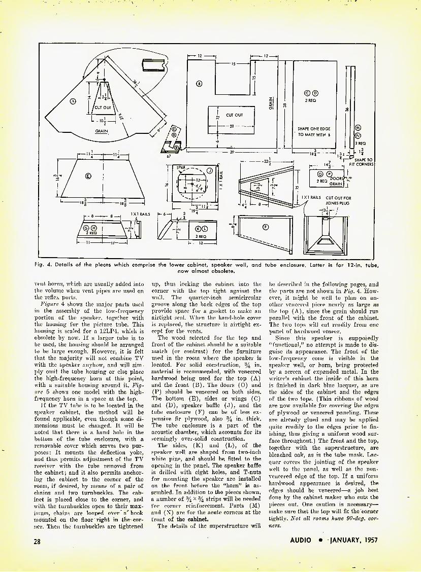
Fig. 4. Details of the pieces which comprise the lower cabinet, speaker well, and tube enclosure. Latter is for 12-in. tube, now almost obsolete.
vint horns, which are usually added into the volume when vent pipes are used on the reflex ports.
Figure 4 shows the major parts used in the assembly of the low-frequency portion of the speaker, together with the housing for the picture tube. This housing is sealed for a 12LP-J:, which is obsolete by now. If a larger tube is to be used, the housing should be arranged to be large enough. However, it is felt that the majority will not combine TV with the speaker anyhow, and will sim- ply omit the tube housing or else place the high-frequency horn at this point, with a suitable housing around it. Fig- ure 5 shows one model with the high- frequency horn iu a space at the top.
If the TV tube is to be located in the speaker cabinet, the method will be found applicable, even though some di- mensions must be changed. It will be noted that there is a hand hole in the bottom of the tube enclosure, with a removable cover which serves two pur- j^oses: It mounts the deflection yoke, and thus permits adjustment of the TV receiver with the tube removed from the cabinet; and it also permits anchor- ing the cabinet to the corner of the room, if desired, by means of a pair of chains and two turnbuckles. The cab- inet is placed close to the corner, and with the turnbuckles open to their max- imum, chains are looped over a hook mounted on the floor right in the cor- ner. Then the turnbuckles are tightened
up, thus locking the cabinet into the corner with the top tight against the wall. The quarter-inch semicircular groove along the back edges of the top provide space for a gasket to make an airtight seal. When the hand-hole cover is replaced, the structure is airtight ex- cept for the vents.
The wood selected for the top and front of the cabinet should be a suitable match (or contrast) for the furniture used in the room where the speaker is located. For solid construction, % in. material is recommended, with veneered hardwood being used for the top (A) and the front (B). The doors (0) and (P) should be veneered on both sides. The bottom (E), sides or wings (C) and (D), speaker baffle (J), and the tube enclosure (F) can be of less ex- pensive fir plywood, also % in. thick. The tube enclosure is a part of the acoustic chamber, which accounts for its seemingly over-solid construction.
The sides, (K) and (L), of the speaker well are shaped from two-inch white pine, and should be, fitted to the opening in the panel. The speaker baffle is drilled with eight holes, and T-nuts for mounting the speaker are installed on the front before the "horn" is as- sembled. In addition to the pieces shown, a number of % x % strips will be needed for corner reinforcement. Parts (M) and (X) are for the acute corners at the front of the cabinet.
The details of the superstructure will
be described in the following pages, and the parts are not shown in Fig. 4. How- ever, it might be well to plan on an- other veneered piece nearly as large as the top (A), since the grain should run parallel with the front of the cabinet. The two tops will cut readily from one panel of hardwood veneer.
Since this speaker is supposedly "functional," no attempt is made to dis- guise its appearance. The front of the low-frequency cone is visible in the speaker well, or horn, being protected by a screen of expanded metal. In the writer's cabinet the inside of this horn is finished in dark blue lacquer, as are the sides of the cabinet and the edges of the two tops. (Thin ribbons of wood are now available for covering the edges of plywood or veneered paneling. These are already glued and may be applied quite readily to the edges prior to fin- ishing, thus giving a uniform wood sur- face throughout.) The front and the top, together with the superstructure, are bleached oak, as is the tube mask. Lac- quer covers the jointing of the speaker well to the panel, as well as the non- veneered edge of the top. If a uniform hardwood appearance is desired, the edges should be veneered—a job best done by the cabinet maker who cuts the pieces out. One caution is necessary— make sure that the top will fit the corner tightly. Not all rooms have 90-deg. cor- ners.
28 AUDIO • JANUARY, 1957

PIUS performance... PLUS value
...fora C/fEr/M€/
Jensen Hypex Horns and Lifetime Driver Units
are way ahead in power rating ... in efficiency . . .
in dependability. They pack a terrific "punch" to
penetrate high noise levels ... to project sound
over great distances. They are loaded with features
that mean sturdiness, convenience and reliability.
And you pay no more for all these PLUS values!
Jensen Hypex Horns and Lifetime Driver Units
are standout members of the new Jensen Professional
Series of loudspeakers especially designed for indus-
trial commercial and institutional sound systems.
Also included are Hypex Paging Projectors; Speech
Master speakers; High Fidelity Projector; 2-way
coaxial and 3-way Triaxial* High Fidelity speakers;
Extended Range speakers; Weather Master outdoor
speakers; transformers, level controls and accessories. •TM Reg.
We'd like to send you a copy of Catalog 1070. Send for copy today.
:o; :<> :o: :o::«:o: :c> :o: :<>: :o: ;<<: :o: :o: :o: :o: :<>::«:o: :<>: :o::«:o:»; :«• s. o: ;«• :o: :<>: :o::«:o: :o: a :o:;o: :<>: ;<>: ;<>: :« »; .<S LIFETIME GUARANTEE « jC^ D-30; D-40 and DD-100 Lifetime Driver Units. W M Every Lifetime Driver Unit is unconditionally guaranteed for life against failure W. when operated according to the instructions accompanying the unit. Should any Lifetime Driver Unit become inoperative at anytime under these ft conditions, it will be repaired or replaced at our option entirely free from any W service charge. „ v, . ^ The instruction sheet supplements and is a part of the warrant/ under which ^ & the Lifetime Guarantee is extended. :Y: JENSEN MANUFACTURING COMPANY :« :« :o: :o: :<>::o: :<5> St ■<>: :<>: :<>: :<i :o: '<>: s>: <>: st :o: :o: ;o:»:»: :o: :o: ;o; :o: s>; :o; :o: ;«•: :o; ;<■: x>: ;o: ;o: ;<x :o; :o: .o.
New and already famous! Jensen RT-20 Functional rectangular horn of molded glass reinforced polyester.
MANUFACTURING COMPANY Division of THE MUTER COMPANY 6601 S. LARAMIE, CHICAGO 38, ILLINOIS
In Canada: Copper W/'re Products Co., Ltd.
Jensen £//"£///}/£ drwers are guaranteed for a lifetime
DD-100 First Super Power Driver available
D-30 New high rating for performance and dependability
D-40 Higher efficiency and higher power
AUDIO • jANUARY, 1957 29
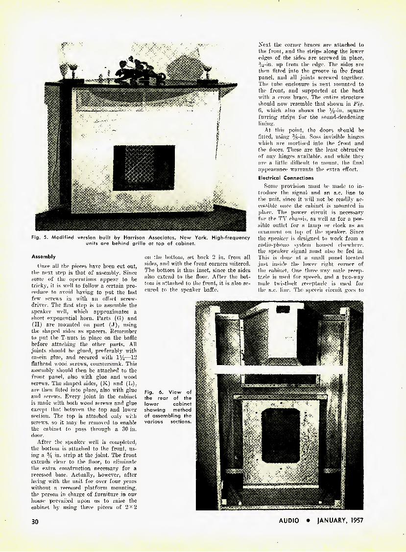
Next the corner braces are attached to the front, and the strips along the lower edges of the sides are screwed in place, R4-in. up from the edge. The sides are then fitted into the groove in the front panel, and all joints screwed together. The tube enclosure is next mounted to the front, and supported at the back with a cross brace. The entire structure should now resemble that shown in Fig. 6, which also shows the %-in. square furring strips for the sound-deadening lining.
At this point, the doors should be lifted, using %-in. Soss invisible hinges which are mortised into the front and the doors. These are the least obtrusive of any hinges available, and while they are a little difficult to mount, the final appearance warrants the extra effort. Electrical Connections
Some provision must be made to in- troduce the signal and an a.c. line to the unit, since it will not be readily ac- cessible once the cabinet is mounted in place. The power circuit is necessary for the TV chassis, as well as for a pos- sible outlet for a lamp or clock as an ornament on top of the speaker. Since the speaker is designed to work from a radio-phono system housed elsewhere, the speaker signal must also be fed in. This is done at a small panel located just inside the lower right corner of the cabinet. One three-way male recep- tacle is used for speech, and a two-way male twistlock receptacle is used for the a.c. line. The speech circuit goes to
Fig. 5. Modified version built by Harrison Associates, New York. High-frequency units are behind grille at top of cabinet.
Assembly
Once all the pieces have been cut out, the next step is that of assembly. Since some of the operations appear to be tricky, it is well to follow a certain pro- cedure to avoid having to put the last few screws in with an offset screw- driver. The first step is to assemble the speaker well, which approximates a short exponential horn. Parts (G) and (H) are mounted on part (J), using the shaped sides as spacers. Kemember to put the T-uuts in place on the baffle before attaching the other parts. All joints should be glued, preferably with casein glue, and secured with 1^4—12 flathead wood screws, countersunk. This assembly should then be attached to the front panel, also with glue and wood screws. The shaped sides, (K) and (L), are then fitted into place, also with glue and screws. Every joint in the cabinet is made with both wood screws and glue except that between the top and lower section. The top is attached only with screws, so it may be removed to enable the cabinet to pass through a 30-in. door.
After the speaker well is completed, the bottom is attached to the front, us- ing a %-in. strip at the joint. The front extends clear to the floor, to eliminate the extra construction necessary for a recessed base. Actually, however, after living with the unit for over four years without a recessed platform mounting, the person in charge of furniture in our house prevailed upon us to raise the cabinet by using three pieces of 2x2
on the bottom, set back 2 in. from all sides, and with the front corners mitered. The bottom is thus inset, since the sides also extend to the floor. After the bot- tom is attached to the front, it is also se- cured to the speaker baffle.
Fig. 6. View of the rear of tbe lower cabinet showing method of assembling tbe various sections.
30 AUDIO • JANUARY, 1957
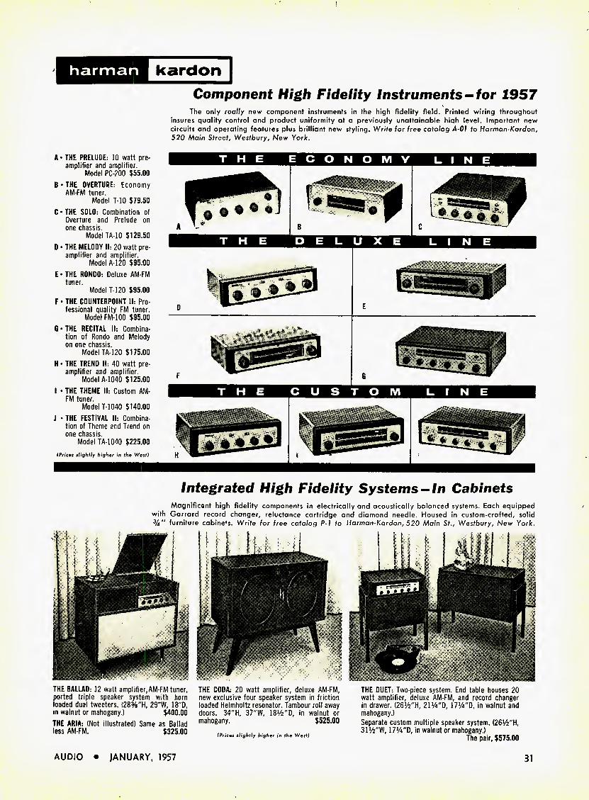
harman kardon
A - THE PRELUDE: 10 watt pre- amplifier and amplifier.
Model PC-200 $55.00 B-THE OVERTURE: Economy
AM-FM tuner. Model T-10 $79.50
C • THE SOLO: Combination of Overture and Prelude on one chassis.
Model TA-10 $129.50 D-THE MELODY II: 20 watt pre-
amplifier and amplifier. Model A-120 $95.00
E- THE RONDO: Deluxe AM-FM tuner.
Model 1-120 $95.00 F • THE COUNTERPOINT II: Pro-
fessional quality FM tuner. Model FM-100 $95.00
G-THE RECITAL II: Combina- tion of Rondo and Melody on one chassis.
Model TA-120 $175.00 H • THE TREND II: 40 watt pre-
amplifier and amplifier. Model A-1040 $125.00
I • THE THEME II: Custom AM- FM tuner.
Model T-1040 $140.00 J • THE FESTIVAL II: Combina-
tion of Theme and Trend on one chassis.
Model TA-1040 $225.00 (Prices slightly higher in the West)
Component High Fidelity Instruments-for 1957
The only really new component Instruments in the high fidelity field. Printed wiring throughout insures quality control and product uniformity at a previously unattainable hiah level. Important new circuits and operating features plus brilliant new styling. Write for free catalog A-01 to Harman-Kardon, 520 Main Street, Westbury, New York.
Integrated High Fidelity Systems-In Cabinets
Magnificant high fidelity components in electrically and acoustically balanced systems. Each equipped with Garrard record changer, reluctance cartridge and diamond needle. Housed in custom-crafted, solid %" furniture cabine's. Write for free catalog P-l to Harman-Kardon, 520 Main St., Westbury, New York.
THE BALLAD: 12 watt amplifier, AM-FM tuner, ported triple speaker system with horn loaded dual tweeters. (28%'^, 29"W, IS'-D, in walnut or mahogany.) $400.00 THE ARIA: (Not illustrated) Same as Ballad less AM-FM. $325.00
THE CODA; 20 watt amplifier, deluxe AM-FM, new exclusive four speaker system in friction loaded Helmholtz resonator. Tambour roll away doors. 34"H, 37"W, ISV^'D, in walnut or mahogany. $525.00
(Prices slightly higher in the West)
THE DUET: Two-piece system. End table houses 20 watt amplifier, deluxe AM-FM, and record changer in drawer. (261/2"H, 211/4"D, 17%"D, in walnut and mahogany.) Separate custom multiple speaker system. (26V2"H, SIW'W, 17!/4"D, in walnut or mahogany.)
The pair, $575.00
AUDIO • JANUARY, 1957 31
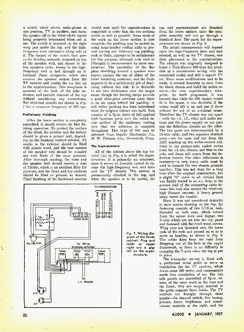
a switch which selects radio-phono in one position, TV in another, and turns the speaker off in the third—both inputs being properly terminated when not in use. The switch is mounted on the right wing just under the top. and the high- frequency horn attenuator along side of it. The output of the switch then goes to the dividing network, mounted on top of the speaker well, and thence to the two speakers units. Access to the high- frequency unit is had through an 8- terminal J'ones receptacle, which also receives the speaker output from the TV receiver and carries the a.c. line up to the superstructure. This receptacle is mounted at the back of the tube en- closure, and permits removal of the top without unsoldering any connections. The electrical circuits are shown in Fig. 7 for a crossover frequency of 900 cps.
Preliminary Finishing
After the lower section is completely assembled, it should receive its first fin- ishing operation. To protect the surface of the wood, the interior and the bottom should be given a primer coat, depend- ing on the finishing method selected. All cracks in the exterior should be filled with plastic wood, and the rear corners of the speaker well should be rounded out with fillets of the same material. After thorough sanding, the sides and the speaker well should receive a coat of Firzite, which is an excellent filler for plywood, and the front and top surfaces should be filled or primed, as desired. Final finishing of the hardwood exterior
should wait until the superstructure is completed in order that the two sections match as well as possible. Since most of the work on the lower section is now complete, the padding may be tacked in, using large-headed roofing nails to pre- vent tearing out. Ordinary rug padding, such as Ozite, appears to be satisfactory for this purpose, although rock wool or Fibreglas is recommended by some con- structors. The possibility of the fine glass shredding around a speaker cone argues against the use of either of the latter insulating materials, and the Ozite appears to do a satisfactory job of dead- ening without this risk. It is desirable to use two thicknesses over the larger areas, though the furring strips provide a good absorptive covering since there is an air space behind the padding. A still better padding has been introduced since the original cabinet was built. This consists of a %-in. layer of felt applied with linoleum paste over the entire in- side surface of the enclosure, making sure that the adhesion is complete throughout. This type of felt may be obtained from Ingalls Electronics Co., 30 W. Putnam Ave., Greenwich, Conn.
The Superstructure
All of the cabinet above the top let- tered (A) in Fig. 4 is called the super- structure. It is primarily an ornament, since it serves no function except to en- close the high-frequency unit and horn and the TV chassis. This section is permanently attached to the top, and when the speaker is to be moved, the
TO SUPERSTRUCTURE
Fig. 7. Wiring dia- gram of the lower cabinet. Plug and cable at upper right are a pig- tail on the super-
structure.
top and superstructure are detached from the lower cabinet, since the com- plete assembly will not go through a standard door. The parts for the super- structure are shown in Fig. 8.
The actual measurements will depend upon the high-frequency horn and unit selected, as well as the TV chassis, and their placement in the superstructure. The cabinet was originally designed to house a Tech-Master 630-type kit, avail- able at a considerable saving over the completed model, and still a superb TV set. Since some modifications had to be made, it seemed desirable to start from the blank chassis and build the entire re- ceiver—the true experimenter's view- point. As work progressed, it was learned that while the 630 chassis would fit in the space, it was doubtful if the writer could lift it up and put it there without the aid of an overhead crane. Therefore the TV chassis was cut apart —with the r.f., i.f., video and audio sec- tions and the power supply on one part and the deflection circuits on the other. The two parts are interconnected by a 13-wire cable, and two separate shielded pairs—one for sync and one from the AGC winding on the width-control coil. Feed to the picture-tube socket comes from the r.f.-etc. chassis, and that to the yoke and focus coil comes from the de- flection chassis. One other refinement is necessary—a very heavy cable must be used to connect the two chassis grounds together. This was not done for a long time after the original construction, but a slight "S" curve in all vertical lines was finally traced to an a.c. drop in the ground lead of the connecting cable be- cause this lead also carries the relatively high filament current. A heavy ground strap cured the trouble.
Since it was not considered desirable to have screws showing on the top, the fastening consists of two 5/16-in. rods, threaded on both ends, which extend from the center deck and engage two T-nuts which are set into the top panel and fastened with flat-head wood screws. Wing nuts are threaded onto the lower ends of the rods and peened on so as to serve as handles, as shown in Fig. 9. The cotter keys keep the rods from dropping out of the hole in the upper framework, so there is no difficulty in engaging the T-nuts when the top is put in place.
The triangular cut-out is fitted with a perforated metal grille to serve as ventilation for the TV receiver, which draws some 300 watts, and consequently needs free circulation of air. The two side panels are assembled of %-in. ve- neer, of the same wood as the tops and the front; they are simply screwed to the grille support from inside. The TV controls are brought through these panels—the channel switch, fine tuning, picture, focus, brightness, and sound- volume controls at the right, and the
32 AUDIO • jANUARY, 1957

ALL THAT IT TAKES TO MAKE A SPEAKER GREAT
A great loudspeaker preserves the essence of high fiiielity. This essence is the accurate reproduction of complex sound waves of varying magnitudes without distortion. What you hear is lifelike reproduction. It is achieved by thorough acoustical research and engineering, excellent basic design, precision manufacture and assembly, meticulous attention to detail.
JBL Signature Loudspeakers are built around the four-inch voice coil. The coil is made of wire ribbon wound on its narrower edge. Frames are rigid castings. Magnetic circuitry is designed to make maximum use of magnet materials, to eschew superfluous metal, and to avoid stray magnetic fields.
Added to these more obvious differences in JBL Signature Speaker construction are the constant refining of each minute detail, the unflagging, meticulous care with which the precision parts are assembled. These are details you cannot see, but they are most important to what you hear.
These are the reasons why JBL Signature Loudspeakers are the most efficient to be found anywhere. These are the rea- sons why JBL Signature Speakers cover the audio spectrum with such outstanding smoothness... why they make of "every note a perfect quote." Excellent design, painstaking care — these are what it takes to make a speaker great. There is no short cut.
For free catalog and technical bulletins describing JBL Signature Loudspeakers, write to James B, Lansing Sound, Inc. 2439 Fletcher Drive, Los Angeles 39, California.
"JBL" means James B. Lansing Sound, Inc.
AUDIO • JANUARY, 1957 33
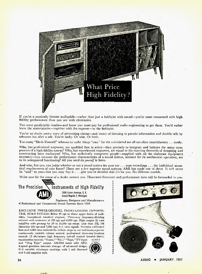
If you're a musically literate audiophile—rather than just a hobbyist with sound—you're more concerned with high fidelity performance than you are with electronics.
You want predictable results—and know you must pay for professional audio engineering to get them. You'd rather leave the uncertainties—together with the expense—to the hobbyist.
You're no doubt pretty wary of advertising claims—and weary of listening to pseudo information and double talk by salesmen hot after a sale. You're lucky. Or wise. Or both.
Too many "Do-it-Yourself" schemes to make things "easy" for the uninitiated are all too often unsatisfactory . . . costly.
Who, but professional engineers, are qualified first to select—then precisely to integrate and balance the many com- ponents of a high fidelity system? Who, but experienced engineers, are equal to the exacting demands of designing and constructing horn enclosures? Who, but technically competent people—supplied with all the elaborate equipment necessary—can measure the performance characteristics of a sound system, account for its mechanical operation, see to its unimpaired functioning? All you need do yourself is listen.
And who, but you, can judge whether or not a sound system fits your ear . . . your recordings . . . the individual acous- tical requirements of your home? There are a few superior sound systems. AMI has made one of them. It will never be "sold" to you—but you may buy it . . . after you've decided that it's for you. Six different models.
Write now for the name of a dealer nearest you. Illustrated literature and performance data will be forwarded to you.
The Precision \ Instruments of High Fidelity
1500 Union Avenue, S. E. Grand Rapids 2, Michigan
Engineers, Designers and Manufacturers Professional and Commercial Sound Systems Since 1909.
EXCLUSIVE THREE-CHANNEL FRONT-LOADED EXPONEN- TIAL HORN SYSTEM: Below 45 cps to above upper limits of audi- bility. Exceptional transient response. Three-way frequency-dividing network with cross-over at 550 cps and 4,000 cps. High output 22 watt amplifier with preamp for 20 to 20,000 cps range. Less than 2% IM distortion (60 cps and 7,000 cps; 4::1 ratio signal). Precision calibrated bass and treble tone controls for definite steps in cut and boost; separate continuously variable volume control: professional three-step loudness control: 12 db/octave high frequency roll-off control (scratch filter); equalization controls. "Tuner," "Mic," "Tape," TV input ' 1^^iI
B(
E0^
and "Mag Tape" output. AM-FM tuner with AFC: 4-speed precision intermix changer of advanced design; G-E variable reluctance cartridge with 1 mil diamond and 3 mil sapphire styli.
34 AUDIO • )ANUARY, 1957
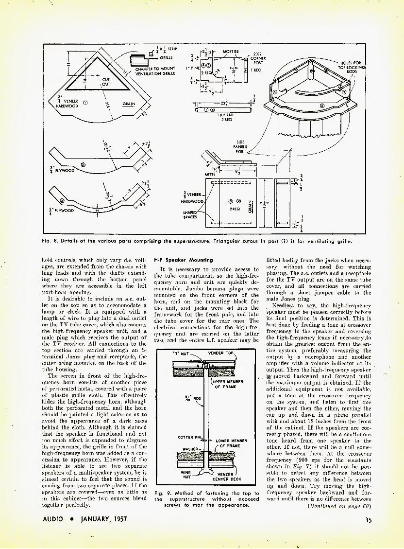
Fig. 8. Details of the various parts comprising the superstructure. Triangular cutout in part (1) is for ventilating grille.
hold controls, which only vary d.c. volt- ages, are extended from the chassis with long leads and with the shafts extend- ing down through the bottom panel where they are accessible in the left port-horn opening.
It is desirable to include an a.c. out- let on the top so as to accommodate a lamp or clock. It is equipped with a length of wire to plug into a dual outlet on the TV tube cover, which also mounts the high-frequency speaker unit, and a male plug which receives the output of the TV receiver. All connections to the top section are carried through an 8- terminal Jones plug and receptacle, the latter being mounted on the back of the tube housing.
The screen in front of the high-fre- quency horn consists of another piece of perforated metal, covered with a piece of plastic grille cloth. This effectively hides the high-frequency horn, although both the perforated metal and the horn should be j>ainted a light color so as to avoid the appearance of a dark mass behind the cloth. Although it is claimed that the speaker is functional and not too much effort is expanded to disguise its appearance, the grille in front of the high-frequency horn was added as a con- cession to appearance. However, if the listener is able to see two separate speakers of a multispeaker system, he is almost certain to feel that the sound is coming from two separate places. If the speakers are covered—even as little as in this cabinet—the two sources blend together perfectly.
H-F Speaker Mounting
It is necessary to provide access to the tube compartment, so the high-fre- quency horn and unit are quickly de- mountable. Jumbo banana plug.s were mounted on the front corners of the horn, and on the mounting block for the unit, and jacks were set into the framework for the front pair, and into the tube cover for the rear ones. The electrical connections for the high-fre- quency unit are carried on the latter two, and the entire h.f. speaker may be
"T" NUT^^ VENEER TOP.
s
(upper member OF FRAME
V/ *00^
COTTER PIN^ 3 =» LOWER MEMBER WASHER-* ^ OF FRAME
f =1
NUT CENTER DECK
Fig. 9. Method of fastening the top to the superstructure without exposed
screws to mar the appearance.
lifted bodily from the jacks when neces- sary, without the need for watching phasing. The a.c. outlets and a receptacle for the TV output are on the same tube cover, and all connections are carried through a short jumper cable to the male Jones plug.
Needless to say, the high-frequency speaker must be phased correctly before its tinal position is determined. This is best done by feeding a tone at crossover frequency to the speaker and reversing the high-frequency leads if necessary to obtain the greatest output from the en- tire system, preferably measuring the output by a microphone and another amplifier with a volume indicator at its output. Then the high-frequency speaker is- moved backward and forward until the maximum output is obtained. If the additional equipment is not available, put a tone at the crossover frequency on the system, and listen to first one speaker and then the other, moving the ear up and down in a plane parallel with and about 18 inches from the front of the cabinet. If the speakers are cor- rectly phased, there will be a continuous tone heard from one speaker to the other. If not, there will be a null some- where between them. At the crossover frequency (900 cps for the constants shown in Fig. 7) it should not be pos- sible to detect any difference between the two speakers as the head is moved up and down. Try moving the high- frequency speaker backward and for- ward until there is no difference between
{Continued on page 60)
AUDIO • JANUARY, 1957 35
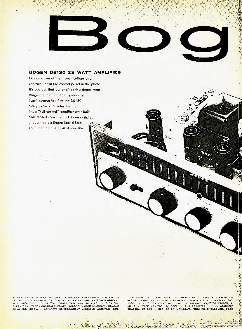
BOGEN DB130 35 WATT AMPLIFIER
Glance down at the "specifications and
controls" or at the control panel in the photo.
It's obvious that our engineering department
(largest in the high-fidelity industry)
hasn't spared itself on the DB1 30,
Many experts consider this the
finest "full-control" amplifier ever built.
Spin those knobs and flick those switches at your nearest Bogen Sound Salon.
You'll get the hi-fi thrill of your life.
POWER: 35 WATTS, PEAK: TOO WATTS - FREQUENCY RESPONSE: 15-30000 CPS WITHIN O 5DB • DISTORTION: 0,3". AT 35 WATTS • INPUTS: LOW MAGNETIC. HIGH MAGNETIC, HI-FI CRYSTAL, TUNER. TAPE, AUXILIARY (Z> • OUTPUTS: SPEAKER ' S i , TAPE - CONTROLS: POWER ( ON-OFF ) • CONTI NUOUSLY VARI ABLE BASS AND TREBLE • SEPARATE CONTINUOUSLY VARIABLE LOUONESS CON-
TOUR SELECTOR • INPUT SELECTOR: PHONO, RADIO. TAPE. AUX. 7-POSITION RECORD EQUALIZER • INFINITE DAMPING CONTROL* LO FILTER (FLAT, 50C. lOOC) • HI FILTER (FLAT. 8KC, 4KC I ■ SPEAKER SELECTOR SWITCH: A, AB, B • TAPE MONITOR (ON-OFF1 . AUX ADJUSTER • HUM ADJUSTER CHASSIS: $ 1 15.00 • BLOND.E OR MAHOGANY-Fl NI SHED ENCLOSURE, S7,50

because it sounds better . . .
Boom HIGH-FIDELITY
A UNITRONICS CORPORATIOM AFFILIATE
what
the 'sound men'
say...
Anton Schmitt,Harvey Radio, known to thousands of Neiv York audiophiles as one of the most knowledgeable hi-fi consultants in our industry.
" / get lots of calls for Bogen from the high-fldelity fans who really know what they're doing. This is especially true of Bogen's premium amplifiers and tuners. And as far as the budget-conscious beginners go, I've started a lot of them out on Bogen's DB110 12 watter . . . and most of them wind up as confirmed Bogen enthusiasts.
"I handle many fine brands of equipment here at Harvey. I'm sure that none of these manufacturers would object to my saying that Bogen's complete line of tuners, amplifiers, receivers and record players is a marvelous hi-fi value throughout."
HARVEY RADIO COMPANY NEW YORK CITY
Have you read our new 56-page edition of "Understanding High Fidelity"? Send S5(f to Dept. AM. David Bogen Co., Inc., P.O. Box 500, Pavamus, New Jersey.

System Simplicity in Audio
R. C. CHAPLICK :
The trend toward duplication—or even triplication—of controls in a high fidelity system is looked upon by this author as unnecessary, use- less, and inconvenient. Furthermore, he tells you what to do about it.
FM TUNER ^ ON/OFF TUNING
DISC REPRODUCER
ON/OFF
PASSIVE DISC EQUALIZER ^
5 CHARACTERISTICS
t-
TAPE REPRODUCER-
RECORDER
MIKE GAIN LINE GAIN ^ ^ ON/OFF
"1 FIXED FIXED GAIN HEARING <
1 1 FIXED PRELIMINARY MIXER CONTOUR p 1 POWER AMPLIFIER COMPENSATION r l i
AMPLIFIER
ONE ON/OFF SWITCH r FOR ALL EQUIPMENT I FIXED
CROSSOVER NETWORK
ni! LOUDSPEAKER
SYSTEM
Fig. 2. Block diagram of ideal arrangement tor an audio system.
The major aim of this article is to advocate "system simplicity" and to show that it can be employed to im-
prove an audio system. Components re- cently featured in audio magazines show a trend towards increasing complexity. Although these gadgets are impressive looking, they require great skill to man- ipulate the myriads of knobs, My opin- ion is that many systems have overgrown and that the average audio enthusiast can achieve superior results by system simplification. Before system simplicity can be discussed intelligently,, the object of an audio system should be known. My definition of a good music system is one that reproduces sound realistically— neither adding nor taking away, "Hold- ing, as it were, a mirror up to nature." There must be no overemphasis of high or low frequencies. Concert-hall realism is not achieved by shaking windows with low frequencies or by hurting ears with high frequencies. 1 must add to the dis- cussion of a good sound reproducing sys- tem, the plea that the listener attend as many live concerts as possible. Reproduc- tion of sound may be pleasing but can never be more "real" than the actual per- formance. Moreover, the listener should have more opportunities to "keep his ear calibrated" by comparing the output of his system with "the real thing."
The current trend in the purchase of audio equipment is the selection of in- dividual components by the audiofan who then assembles them into a system.
* 10001 McKenney Ave., Silver Spring, Md.
Figure 1 is a block diagram of a system produced in this manner. This proced- ure has many disadvantages. First, there is no assurance that the components are electrically compatible. Second, there are too many controls which nullify or dupli- cate each other, Third, there are just too many controls. My conclusion after four years of buying or building components is that he who wishes to assemble a good system should obtain the guidance of a professional electro-acoustic engi- neer, one who can criticize objectively, who can test a system thoroughly, and who is not interested in selling any par- ticular brand of equipment. The latter
requirement is the most important. Then, a new system can be engineered to meet any needed specification, or an existing system can be simplified and improved. In either ca.se the consultant will be able to prevent many errors and to provide system engineering.
The ideal simplified system should be defined before I tell how my own system was simplified and improved. The general objective is to reproduce sound realisti- cally at any level. The frequency response will cover the audible range, the power output will be adequate for the needs of the listening room, and the distortion will be inaudible. Controls and adjust- ments will be kept to a minimum, and where equalization is needed, fixed pas- sive networks will be employed. From these generalities a block diagram (Fig. 2) of the ideal system can be made.
With the advice of the consultant, J devised the audio system described in the following paragraphs. Component cir- cuit diagrams are omitted since conven- tional circuits are used. The number of controls was reduced to a minimum. Broadcast control room techniques were employed, and each unit was equipped with its own power supply and fuse. Individual parts of a unit were oriented for minimum hum. Standard telephonic techniques were employed in designing the wiring of the units. Source output Fig. 1. Block diagram of system before simplification.
38 AUDIO • JANUARY, 1957
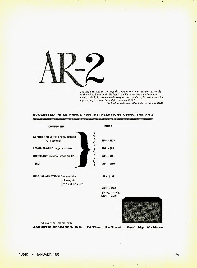
The AR-2 speaker system uses the same acoustic suspension principle as the AK-I. Because of this lad it is able to achieve a perlormance quality which, by pre-acoustic suspension standards, is associated with a price range several times higher than its 96.00*
in birch or mahogany; other finishes S9.00 and 102.00
SUGGESTED PRICE RANGE FOR INSTALLATIONS USING THE AR-2
COMPONENT PRICE
AMPLIFIER (10-30 clean watts, complete with controls)
RECORD PLAYER (changer or manual)
CARTRIDGE(S) (diamond needle for LP)
TUNER
$75 - - $125
$40 - - $60
$20 - - $45
$70 - - $100
AR-2 SPEAKER SYSTEM Complete with enclosure; size 13'/2" x 11%" x 24")
Literature on request from: ACOUSTIC RESEARCH, INC.
$89 - - $102
$294 - ■ $432
(phonograph only, $224 - - $332)
24 Thorndlke Street Cambridge 41, Mass.
AUDIO • JANUARY, 1957 39
voltages were set at fixed valves to meet input requirements of the Control Unit. The stepped Hearing Contour Compen- sator reduces the level by an amount, shown on the compensator setting. The single gain control is therefore usable over its entire rotation, not just the first ten or twenty degrees.
An audio system is divided into three parts: sources, sinks, and controls. In turn, each of the three parts has sub- divisions whose specifications and meth- od of simplification now can be discussed individually.
Sources
Disc Reproducer. Disc reproduction is designated exclusively for SS1/^ rpm LP discs in manual operation. Since all of of the program material which interests me is available on LP discs, only a single turntable speed is needed. I frequently wonder why turntable manufacturers do not produce a good single speed, SSVs- rpm turntable. Elimination of the un- wanted speeds, pulleys, and idlers is a form of simplification. A good quality magnetic cartridge completes the disc reproducer.
FM-tuner. The tuner has a.f.c. and a tuning indicator. Only two controls are necessary—the on-off switch and the tun- ing control. The output voltage was set at an average peak level of 0.5 v. rms. Equalized high-quality headphones can be plugged in for night listening.
Tape Reproducer-Recorder. This unit has NARTB equalization. Two gain con- trols are used in the "record" mode of operation: One in the "microphone" channel, one in the "line" channel. A VU meter is used. There is no gain con- trol in "playback." Provision for both tape and input monitoring by headphone or loudspeaker is made. An Ampex 600 meets these requirements.
Sinks
Power Amplifier. The frequency re- sponse of the basic amplifier is flat within ± 1 db from 20 to 20,000 cps. When the adult human car is shown to hear beyond 20,000 cps, then I'll start worrying about extending the frequency response. Fixed compensation for loud- speaker characteristics have been added. The amplifier is designed to furnish one- half the 25-watt maximum power at 0.6 v. rms input, allowing three decibels of reserve power for possible overswing. The internal generator impedance has been adjusted by test for optimum damp- ing of the associated loudspeaker system. A pulse from an RC circuit was used in this test, and the amount of inverse feed- back was varied until best damping was secured.
Loudspeaker System. A warble oscil- lator and a calibrated microphone were used to set the proper balance between
high- and low-frequency loudspeakers and to set the equalization for loud- speaker and room acoustics. This equali- zation is permanent since room acoustics change very little from day to day.
Controls
A commercial preamplifier was re- worked into a "Control Unit." Two of the sources listed above were mixed by means of a resistive network into the preliminary amplifier at the proper levels according to the output voltage of each. Because each source has its own power supply, its output signal can be removed by simply cutting off the power. Thus the selector switch could be eliminated. However, a switch was pro- vided for tape playback to eliminate a feedback loop during recording. Tape recording may be monitored by head- phones or by loudspeaker.
Preliminary amplifiers with separate high- and low-frequency controls for disc equalization have a common fault. Although the low-frequency control is intended to effect only the low frequen- cies if also effects the highs, and vice versa in the case of the high-frequency control. Therefore, unless accurate cali- bration has been made of all possible combinations of those controls, front panel markings are far from accurate. Disc equalization has been simplified to a one-knob control. Five equalization curves based on published curves of rep- resentative disc manufacturers are suffi- cient for all discs (old records being taboo). Circuits were designed to switch resistors rather than capacitors to mini- mize the effect of switching transients. The RC values were calculated and then corrected by frequency measurements to yield the proper equalization. The "Rum- ble Filter" was removed entirely since a transcription turntable is used and un- reasonable "bass boost" is avoided.
The main feature of the control unit is the replacement of conventional "bass" and "treble" controls by a "Hearing-Con- tour Compensator." The Hearing-Con- tour Compensator improves the realism of high-quality sound reproduction by compensating for the difference in level between the music produced in the con- cert hall and that reproduced at a neces- sarily lower level in the living room. It compensates for the variations in human hearing sensitivity to sounds of different loudness. The variations in hearing have been measured and have been found quite uniform for persons of normal hearing. They are shown in the Fletcher-Munson Curves of equal loudness. The principle of the Hearing-Contour Compensator operation is based on a study of the differences between Fletcher-Munson Curves, rather than on contour at any one acoustic level. Averages have been selected based on a series of subjective tests which included listening alter-
nately to original sounds and then to the same sounds recorded and reproduced. Most of this testing was made with the orchestra of the Metropolitan Opera in New York and the U. S. Navy Band in Washington, D. C. The Hearing Contour Compensator performs in fixed calibrated steps of 0, 10, 20, 30 and 40 db. These figures indicate the difference in db be- tween original and reproduced program levels. Appropriate attenuation is de- signed into the compensator. In case speech is reproduced, music equalization is completely wrong, since speech should be reproduced at about the same level as it was originally produced. For speech reproduction a switch is provided which retains the attenuation but removes the compensation.
It is important to digress at this point in order to speak again of the value of frequent listening to good orchestras under good concert hall conditions. Many "bifi" fans will find this an illu- minating experience; a few may be dis- couraged and some will staunchly main- tain that the orchestral sounds are much inferior to those reproduced by their "hifi" systems. This will prove the re- vised adage "be they ever so homely there are no ears like your own."
The number of controls in the system was reduced from twenty-one to ten.
CONTROLS Before Simplification
FM tuning control Rumble filter Turnover ] Rolloff ( Selector Volume Loudness
2 level controls Bass Bias adjust Input balance Output balance Line gain Microphone gain 5 on/off switches
After Simplification FM tuning control
Disc equalizer
Gain Hearing Contour
Compensation
Line gain Microphone gain 4 on/off switches
This simplification of my audio system has had several broad results. I now have a positive knowledge of the average acoustic output of my speaker, whether at full volume or low, and the balance is correct for every level. There is no de- pendence on acoustic memory and no extreme overemphasis. Reproduced music sounds close to that I hear in the concert hall. The use of the Hearing Contour Compensator permits the use of the fol- lowing operating technique. After a source is selected, a suitable listening- room loudness level is chosen. The Com- pensator is adjusted to the necessary setting (-10, - 20 phms, etc.) to furnish this loudness level. The gain control is then rotated clockwise fully, fading in the desired sound smoothly with no acoustic shock to the listeners. •
40 AUDIO • JANUARY, 1957
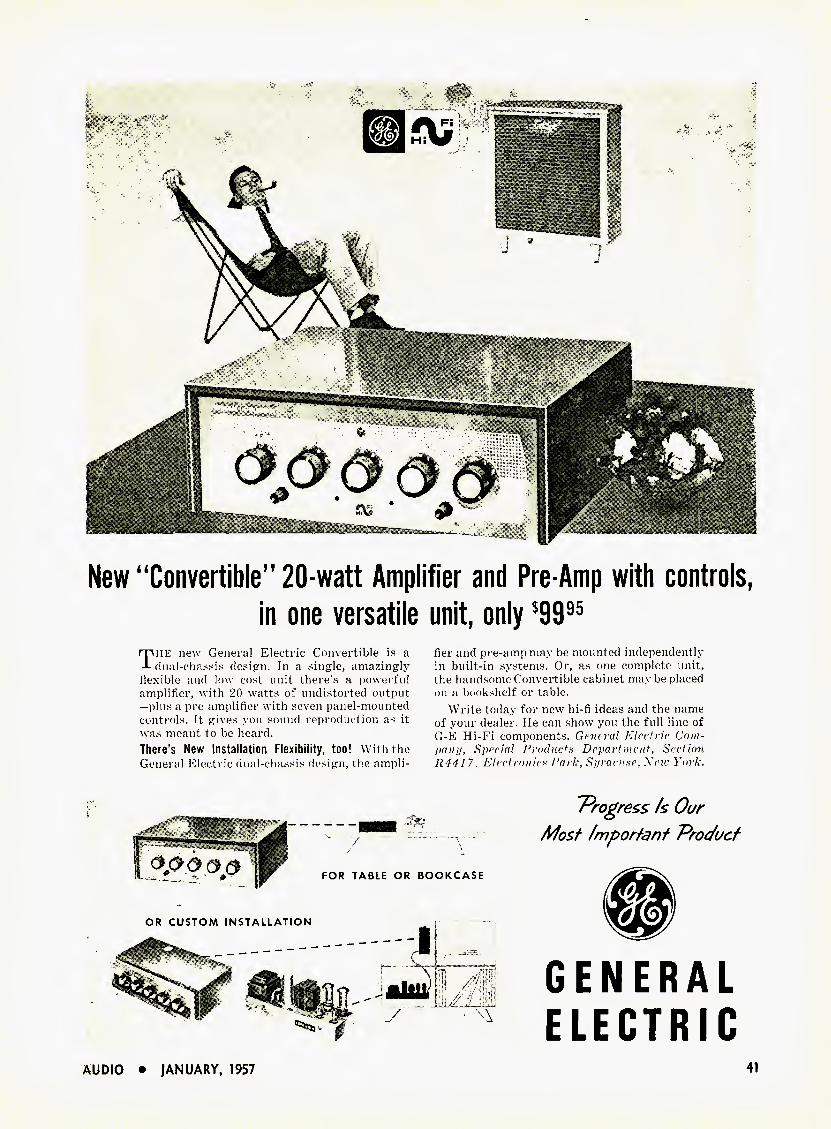
k*-
New "Convertible" 20-watt Amplifier and Pre-Amp with controls,
in one versatile unit, only $9995
The new General Electric Convertible is a dual-chassis design. In a .single, amazingly
flexible and low cost unit there's a powerful amplifier, with 20 watts of undistorted output —plus a pre-amplifier with seven panel-mounted controls. It gives you sound reproduction as it was meant to be heard. There's New Installation Flexibility, too! With the General Electric dual-chassis design, the ampli-
fier and pre-ampmay be mounted independently in built-in systems. Or, as one complete unit, the handsome Convertible cabinet may be placed on a bookshelf or table.
Write today for new hi-fi ideas and the name of your dealer. He can show you the full line of G-E Hi-Fi components. General Electric Com- pany, Special Products Department, Section R441 7, Electronics Park, Syracuse, Neiv York.
T^rogress Is Our
Most Important Product
FOR TABLE OR BOOKCASE
OR CUSTOM INSTALLATION
GENERAL
ELECTRIC
AUDIO • JANUARY, 1957 41

>'
1. BEETHOVEN
Beethoven: The Thirty Two Sonatas (Beethoven Society Edition). Artur Schna- bel, piano. (Limited. Includes the Schna- bel edition of the printed music in two volumes, full-size.)
RCA Victor LM 9500 (13) For many years the famous Beethoven re-
cordings by Schnabel, begun in lOflG and ex- tending through 1939, were the most famous "Society" editions in the record world ; since their end, the earlier volumes have been price- less collector's items, heard by few of us, and all have been treasured far beyond the gen- eral run of 78 rpm issues. The complete 78 rpm series was positively enormous and In- deed was a project of almost unbelievable daring.
Here is the whole business, transferred beautifully to LP, the sides patched together so that you'll never find the old breaks, the quality mostly extremely good. Only in a few spots is there some slight "breaking up" of the more percussive piano tones (though on older phonographs, over the years, we used to think that the huzzy distortions we heard were in the recordings themselves). Most of the sound is clean as a whistle, right through the loudest climaxes. No doubt the weaker spots are the inevitable inner grooves of the old discs. There is some slight hiss, varying from noticeable to almost inaudible. The steadiness of pitch is remarkable, the piano sound, even without higher highs, it magnifi- cent—-as it always seemed in the old days. Luckily, of all musical sounds that of the piano depends least on "hi-ti" highs, as you'll quickly realize here.
^ The Schnabel interpretations remain tops. There are weak places and—unusual for today —numerous slight mistakes. But Schnabel worked in the pre-tape days ; there was no cor- recting then, short of an entire new side and the possibility of more minor slips. It was the first time, or nothing. Schnabel, in any case, is the classic example of the great musi- cian whose fingers did not always keep up with his tremendous musical mind. He was no great technician but he had an astonishing understanding of the shape and meaning of Beethoven. You—any listener—stand directly to benefit by it, as you listen.
The imposing double-volume wood box that holds these recordings also includes the Schnabel edition of the sonatas themselves, the printed notes, with extensive annotations by him in great detail. These aren't minia- ture scores but the fuli, fat volumes, inches thick and feet wide. I can't imagine a better and more inevitable scheme—Schnabel in print and sound.
Maybe you won't want to shell out the fortune required—yet. But plenty of readers, especially those who dabble in piano, will find that KCA really isn't charging too much, when they think it over. I predict a big sale.
One minor gripe. With all the fancy boxing.
* 780 Greenwich St., New York 14, N. Y.
EDWARD TATNALL CAN BY
RCA has packed the 13 records simply in loose white paper envelopes with wax paper inner paokapinp. No identification and yon can't see through the wax paper, so in the end you'll do what I did and go through the whole set removing the wax paper and mark- ing the white envelopes yourself with the side numbers. Otherwise you'll go crazy try- ing to find the disc you're after. A poor economy in a de luxe set like this.
Beethoven: Piano Sonatas Op. 57 C'Ap- passionata"), Op. 111. Ernst Levy.
Unicorn UNLP 1034 Ernst Levy is a "big" pianist and a Beeth-
oven man through and through ; this series brings him to general notice for the first time in this country. (He is Swiss, now an American). Put on his "Appassionata" and you'll soon find out why he is what he is. Bang! Things begin to happen right away, and Peter Bartok's recording must have been sorely taxed to take in the enormous dynamic contrasts in the powerful Levy playing.
The "Appassionata" will delight all who like big piano and lots of drama. It will per- haps startle those who know the work reason- ably well. Levy heps up the drama to an as- tonishing intensity and, in the process, does a few things that won't please all the pian- ists. Lots of pedal, lots of rubato (slowing- down. holding-back), some odd inner voices thrown into the foreground. But almost any- body whose ears are flexible will have to ad- mit the bigness and power of musicianship and of spirit here.
The Opus 111, the last sonata, is just plain superb. In many respects I'll take this over the standard-of-high-interpretation, that of Artur Schnabel. Levy gets more magic, more dignity, more profundity out of some passages than old Schnabel himself. Levy can play slower than anybody and sustain the sense and melodic line ; he plays the incredi- ble last pages of the variations with their sustained trills and enormous complexity in a masterful fashion, both technically and in the wonderful spirit and the sense for shape and line. This isn't piano—it's music.
Yes, a great pianist by many a standard, and the more unusual in that the Levy blood- and-thunder approach is astonishingly old- fashioned, almost of the end of the lOth cen- tury out of Liszt himself. We need a bit of that kind of playing, what with so many harpsichord-like and percussion-style pianists now operating !
See also other Levy recordings from Uni- corn.
Beethoven: Piano Sonatas Op. 109, 110, 111. Glen Gould. Columbia ML 5130
In extreme contrast, this young pianist, scarcely beyond 20, tackles the three biggest giants in the sonata world and does a credit- able job, with fantastically light-fingered tech- nique, much sincerity and musicality. But this sort of music takes years of maturity to pene- trate, for even the greatest pianistic minds. Gould's playings are light, staccato almost.
in the new manner of today's younger pianists, fast, expressive, but in comparison to Levy (and to Schnabel and others) they lack weight, miss much of the larger drama and shape in favor of expressive detail. Some day, probably, he'll do them all over again.
Piano tone is thinner, less massive than Peter Bartok's in the Levy recording and at a lower volume level, probably in order to get all three of the big works onto the one LP record.
Beethoven: Overtures. (Leonore #}, #2, #3; Fidelio, Coriolan.) Boston Symphony, Munch. RCA Victor LM 2015
Such smoothly gorgeous playing I haven't heard in a long time. Here in these overtures, recorded in the old-fashioned big and rather distant manner (no hi-fi close-up telephone bells, no crashing glass, no dynamite explo- sions!). The Boston Symphony shows that it is just as elegant and as polished and as pow- erful as we've been hearing.
The collection is a useful and entertaining one. especially the three Leonores, the first, if 1 remember rightly, actually the last and the second a bass concentrated version of the familiar third. (The Fidelio overture was still another try for the same opera, toned down so as not to steal the operatic thunder as did the too-potent earlier versions.) Decidedly recommended.
Beethoven: Piano Sonatas Op. 10, #2, #3. Friedrich Gulda. London LL 1374
Gulda's light-fingered, rhythmic Beethoven has much of this younger generation in it and will appeal to "the young in heart," as the saying goes and. incidentally, those who have a yen for contemporary jazziness as op- posed to the grandiloquent thunderings of an earlier school of pianism. Gulda is young, Gulda now plays a species of jazz in night clubs, and thus what I say is more than mere theory !
In these two early sonatas he takes the light approach without either hardness or inflexibility and the sound is thoroughly musical—neither the boogie-woogie approach to piano nor yet again, the hard-toned modern "classical" pianism first cousin to boogie in its tone, finds any place here. Gulda's sounds still respect the piano as a lyric instrument, which is more than can be said for many younger pianists' work today.
Recorded piano tone is on the dark side, with edge only in the loudest parts. The louder peaks may buzz a little with the average pickup.
Beethoven: Symphony #6 ("Pastoral"). Berlin Philharmonic, Cluytens.
Angel 35350 The beautiful pale green cover of this Angel
release contains a somewhat odd "Pastoral" that doesn't seem to come to life until the storm, the third movement ; from thence on- ward it is fine.
42 AUDIO • JANUARY, 1957

for the Ultimate
in High Fidelity Listening Pleasure . . .
AUDIO FIDELITY record.n
Not just a Hi-Fi Record . . . hut each a
Tremendous Emotional Experience!
AFLP 1813 12 in. $5.95 AFLP 1814
U-in. $5 95
i PLAZA deTOROS is pmi sM'rt ijj
AFLP 1817 I2-in. $5.95
AFLP 1815 1 2-in. $5 95
WRITE FOR FREE CATALOGUE 'Many other unusual and exciting recordings for the most discriminating collector.
NATIONALLY DISTRIBUTED BY
DAUNTLESS INTERNATIONAL 750 TENTH AVENUE NEW YORK 19, N. Y.
AUDIO • JANUARY, 1957
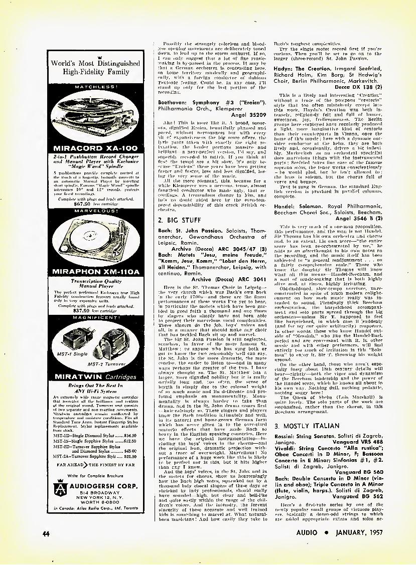
w World's Most Distinguished
High-Fidelity Family
MATCHLESS!
MIRACORD XA-IOO 2-in-l Pushbutton Record Changer and Manual Player with Exclusive
"Magic Wand" Spindle 5 pushbuttons provitU' complete control at thr tniich of a finucrtip. Instantly converts to an automatic Manual Player by insertinti short spimlle. Famous "Manic Wand" spindle intermixes 10" and 12" records, protects your finest recordings.
Cofnplftc with pities and lends attached. 867.50 less cartridnc
MIRAPHON XM-IIOA Transcription Quality
Manual Play er The perfect performer! Embraces true Hiyh Fidelity construction features usually found only in very expensive units.
Complete with pities and leads attached. 837.50 less cartridge
MIR AT WIN Cartridges Brings Out The Best In
AISY Hi-Fi System An extremely wide raime magnetic cartridge that recreates all the brilliance and realism yf the original sound. Turnover unit consists of two separate and non-reacting movements. Miratwin cartridges remain unaffected by temperature and moisture conditions. Fits all Standard Tone Arms. Instant Fingertip Stylus Heplaccment. Stylus replacements available from stock. MST-1D—Single Diamond Stylus $34.50 MST-1S—Single Sapphire Stylus $12.50 MST-2D—Turnover Sapphire Stylus
and Diamond Stylus $45.00 MST-2A—Turnover Sapphire Styli $22.50
FAR AHEAD^ THE FINEST BY FAR
Write for Complete Brochure
AUDIOGERSH CORP. 514 BROADWAY
NEW YORK 12. N. Y. WORTH 6-O8OO
in Canada: Atlas Radio Corp., Ltd. Toronto
Possibly the strangely colorless and blood- less opening movements are deliberately toned down, to lead up to the storm outburst. If so, I oan only suggest that a lot of fine music- making is by-passed in the process. It may be that a German orchestra is contending here, on home territory musically and geographi- cally. with n foreign conductor of dubious Teutonic feeling. Could he. In any case, I'll stand up only for the last portion of the recording.
Beethoven: Symphony #3 ("Eroica''). Philharmonia Orch., Klemperer
Angel 35209 Aha ! This Is more like it. A broad, sonor-
ous. dignified Eroica, beautifully phrased and paced, without nervousness but with every hit of expansiveness the big score offers, the 1\ ric parts taken with exactly the right re- Inxalion. the louder portions massive and brilliant a near-perfect version, I'd say, and superbly recorded to match. If you think at first the tempi are a bit slow, it's only be- <':uise "Eroicas" these years have been getting faster and faster, less and less dignified, los- ing the very sense of the music.
All the more pleasant, this, because for a while Klomperer was a nervous, tense, almost fanatical conductor who made ugly, taut re- cordings. A tremendous change in him, and he's no doubt aided here by the even-tem- pered dependability of this crack British or- chestra.
2. BIG STUFF
Bach: St. John Passion. Soloists, Thom- 1 anerchor, Gewandhaus Orchestra of
Leipsic, Ramin. Archive (Decca) ARC 3045/47 (3)
Bach: Motets ''Jesu.. meine Freude," | "Kemm, Jesu. Komm/' ''Lobet den Herrn,
all Heiden/' Thomanerchor, Leipsig, with | continue, Ramin.
Archive (Decca) ARC 3041 Here is the St. Thomas Choir in Leipsig—
the very church which was Bach's own back in the early 1700s—and these are the finest performances of these works I've yet to hear, in particular the motets which have been gar- bled in good faith a thousand and one times by singers who simply have not been able to project their marvelous vocal complexities. These singers do the job, boys' voices and all. in a manner that should make any choir that has tackled Bach sit up and marvel.
The big St. .John Passion is still neglected, somehow, in favor of the more famous St. Matthew ; as anyone who has sung both or got to know the two reasonably well can say, the St. John is the more dramatic, the more concise, the easier to listen to—and in many ways perhaps the greater of the two. I have always thought so. The St. Matthew has a laiger. more dignified nobility but it is really awfully long and, too often, the sense of length is simply due to the colossal weight of so much music and its deliberate and pro- found emphasis on monumentality. Monu- mentality is always harder to take than drama, and in the St. John drama comes first —hair-raisingly so. These singers and players know the Bach tradition intimately and well, in its natural and home-grown German form which has never given in to the over-sized oratorio effects that have made Bach so heavy in the English speaking countries. Here we have the original instrumentation-—in- cluding the boys' voices in the chorus—and the original lean, dramatic projection with- out a trace of overweight. Marvellous! No performance of a huge work like this is likely to be perfect nor is this, but it hits higher than any I know.
And the boys' voices, in the St. John and in the motets for chorus, show us hearteningly how the Bach high notes, squawked out by a thousand lady choral singers of these days or shrieked by lady professionals, should really have sounded—high, but clear and bell-like and quite easily within the range of the chil- dren's voices. And the intensity, the fervent sincerity of these accurate and well trained kids is something to marvel at. What natural- born musicians I And how easily they take to
Bach's toughest complexities. Try the single motet record first if you're
curious. Then you'll be set to go on to the larger (three-record) St. John Passion.
Hadyn: The Creation. Irmgard Seefried, Richard Holm, Kim Borg; St Hedwig's Choir, Berlin Philharmonic, Markevitch.
Decca DX 138 (2) This is a lively and interesting "Creation"
without a trace of the pompous "oratorio" style that too often mistakenly creeps into this work. Haydn's Creation was both in- tensely, religiously felt and full of humor, sweetness, joy, frolicsomeness. The Berlin groups here employed have regularly produced a light, more imaginative kind of oratorio than their counterparts in Vienna, once the home of th's music : here with a dynamic out- sider conductor at the helm, they are both lively and, occasionally, driven a bit inflexi- bly, Markevitch as an orchestral specialist does marvelous things with the instrumental parts : Seefried takes fine care of the famous soprano solos, the tenor works conscientiously —he would plod, but he isn't allowed to : the bass is solemn, but the chorus full of verve and bounce.
Text is sung in German, the standard Eng- lish version is provided in parallel columns, complete.
Handel: Solomon. Royal Philharmonic, Beecham Chord Soc., Soloists, Beecham.
Angel 3546 B (2) This is very much of a one-man proposition,
this perfoi mance, and the man is not Handel. Sir Thomas has his own orchestra and chorus and. to an extent, his own score—"the entire score has been re-orchestrated by me," he adds as an afterthought to his own notes on the recording, and the music itself has been subjected to "a general readjustment ... on a fairly comprehensive scale." Those who know the doughty Sir Thomas will know what all this means—Handel-Beecham, and a sort of music-making that is both highly alive and. at times, highly irritating.
Old-fashioned, slow-tempo overture, unre- constructed in spite of much modern enlight- enment on how such music really was in- tended to sound. Pleasingly thick Beecham orchestration, the harpsichord accompani- ment and solo parts spread through the big orchestra—unless Sir T. happened to feel like harpsichord, in which case it "suddenly (and for my ear quite arbitrarily) reappears. In other words, those who know Handel out- side of "Messiah," who like the Handel-Bach period and are conversant with it, in other music and with other performers, will find entirely too much of irritation in this "Solo- mon" to enjoy it. Sir T. throwing his weight around.
On the other hand, those who aren't espe- cially fussy about 18th century details will hear—rightly—both the vigor and dynamism of the Beecham leadership and the power of the Handel score, which he knows all about in his own way. Nothing dull, nothing pedantic, nothing soggy here !
The Queen of Sheba (Lois Marshall) is quite lovely. The solo parts of the work are emphasized, rather than the chorus, in this Beecham arrangement.
3. MOSTLY ITALIAN
Rossini: String Sonatas. Solisti di Zagreb, Janigro. Vanguard VRS 488 Vivaldi: String Concetto "Alia rustica"; Oboe Concerti in D Minor, F; Bassoon Concerto in E Minor; Sinfonias #1, #2. Solisti di Zagreb, Janigro.
Vanguard BG 560 Bach: Double Concerto in D Minor (vio- lin and oboe); Triple Concerto in A Minor (flute, violin, harps.). Solisti di Zagreb, Janigro. Vanguard BG 562
Here's a first-rate series by one of the newly popular small groups of virtuoso play- ers. basically a dozen-odd strings to which are added appropriate extras and solos ac-
44 AUDIO • jANUARY, 1957
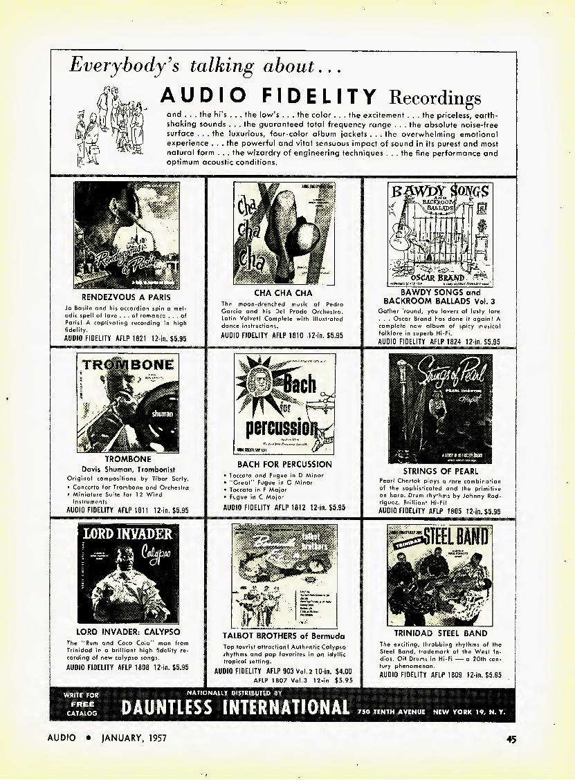
WRITE FOR NATIONAlir DISTRIBUTED BY
DAUNTLESS INTERNATIONAL
Everybody's talking about...
AUDIO FIDELITY Recordings
and . . . the hi's . . . the low's . . . the color . . . the excitement . . . the priceless, earth- shaking sounds . . . the guaranteed total frequency range . . . the absolute noise-free surface . . . the luxurious, four-color album jackets . . . the overwhelming emotional experience . . . the powerful and vital sensuous impact of sound in its purest and most natural form . . . the wizardry of engineering techniques . . . the fine performance and optimum acoustic conditions.
RENDEZVOUS A PARIS Jo Basile and his accordion spin a mel- odic spell of love ... of romance ... of Paris! A capfivafing recording in high fidelity. AUDIO FIDELITY AFLP 1821 12-ln. $5.95
CHA CHA CHA The moon-drenched music of Pedro Garcia and his Del Prado Orchestra. Latin Velvet! Complete with illustrated dance instructions. AUDIO FIDELITY AFLP 1810 .12-in. $5.95
BAWDY SONGS and BACKROOM BALLADS Vol. 3
Gather round, you lovers of lusty lore . . . Oscar Brand has done it again! A complete new album of spicy musical folklore in superb Hi-Fi. AUDIO FIDELITY AFLP 1824 12-in. $5.95
-Tach
r\ . t
percussio
BACH FOR PERCUSSION • Toccata and Fugue in D Minor • "Great' Fugue in G Minor • Toccata in F Major • Fugue in C Major AUDIO FIDELITY AFLP 1812 12 in, $5.95
LORD INVADER: CALYPSO The "Rum and Coca Cola" man from Trinidad in a brilliant high fidelity re- cording of new calypso songs. AUDIO FIDELITY AFLP 1808 12-in. $5.95
TALBOT BROTHERS of Bermuda Top tourist attraction! Authentic Calypso rhythms and pop favorites in an idyllic tropical setting.
AUDIO FIDELITY AFLP 903 Vol. 2 10 in. $4.00 AFLP 1807 Vol.3 12-in $5.95
TRINIDAD STEEL BAND The exciting, throbbing rhythms of the Steel Band, trademark of the West In- dies. Oil Drums in Hi-Fi — a 20th cen- tury phenomenon. AUDIO FIDELITY AFLP 1809 12-in. $5.95
STRINGS OF PEARL Pearl Chertok plays a rare combination of the sophisticated and the primitive on harp. Drum rhythms by Johnny Rod- riguez. Brilliant Hi-Fi! AUDIO FIDELITY AFLP 1805 12 in. $5.95
TROMBONE Davis Shuman, Trombonist
Original compositions by Tibor Serly. • Concerto for Trombone and Orchestra • Miniature Suite for 1 2 Wind
Instruments AUDIO FIDELITY AFLP 1811 12-m. $5.95
AUDIO • JANUARY, 1957 45
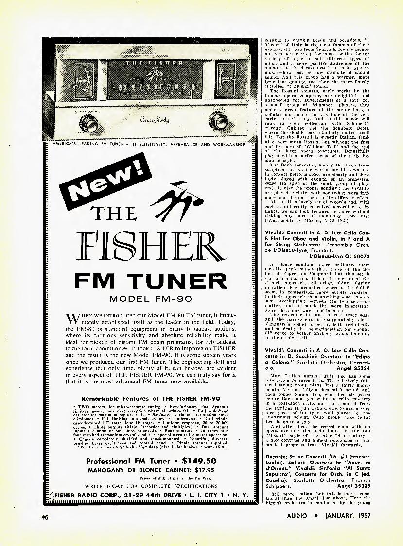
= AMERICA'S LEADING FM TUNER • IN SENSITIVITY, APPEARANCE AND WORKMANSHIP "" Z
HER
FM TUNER
MODEL FM-90
When we introduced our Model FM-SO FM tuner, it imme- diately established itself as the leader in the field. Today,
the FM-80 is standard equipment in many broadcast stations, where its fabulous sensitivity and absolute reliability make it ideal for pickup of distant FM chain programs, for rebroadcast to the local communities. It took FISHER to improve on F1SFIER and the result is the new Model FM-90. It is some sixteen years since we produced our first FM tuner. The engineering skill and experience that only time, plenty of it, can bestow, are evident in every aspect of THE FISHER FM-90. We can truly say for it that it is the most advanced FM tuner now available.
Remarkable Features of THE FISHER FM-90 ■ TWO meters, for micro-accurate tuning. ■ Revolutionary, dual dynamic limiters, assure noise-free reception where all others fail. ■ Full wide-hand detector for maximum capture ratio. ■ Exclusive, variable inter-station noise eliminator. ■ Full limiting on signals as low as 1 microvolt. ■ Dual triode, cascode-tuned RF stage, four IF stages. ■ Uniform response, 20 to 20,000 cycles. ■ Three outputs (Main, Recorder and Multiplex). ■ Dual antenna inputs (72 ohms or 300 ohms balanced). ■ Four controls. ■ 10 tubes plus four matched germanium crystal diodes. ■ Special circuits for meter operation. ■ Chas-sis completely shielded and shock-mounted. ■ Beautiful, die-cast, brushed brass escutcheon and control panel. ■ Dipole antenna supplied. ■ SIZE : 13 7 16" w. x 6i/8" high x 8%" deep (plus 1" for knobs >. ■ we. r: 15 lbs.
Professional FM Tuner ■ $149.50 MAHOGANY OR BLONDE CABINET; $17.95
Prices Slightly Higher in the Far West WRITE IODAY FOR COMPLETE SPECIFICATIONS
FISHER RADIO CORP., 21-29 44th DRIVE • L. I. CITY 1 • N. Y. niitjimimiii n 111111111 n 11 n 111111111111m i iinimi
cording to varying needs and occasions. "I Musicl" of Italy is the most famous of these groups : this one from Zagreb Is for my money an even better group for music, with a better variety of style to suit different types of music and a more positive awareness of the amount of "orchestralness" in each type of music—how big, or how intimate it should sound. And this group has a warmer, more lyric tone quality, too, than the marvellously chiselled 4T Musici" sound.
The Rossini sonatas, early works by the famous opera composer, are delightful, and unexpected too. Divertimenti of a sort, for a small group of "chamber" players, they make a great feature of the string bass, a popular instrument in this time of the very early 19th Century. And so this music will rank in your collection with Schubert's "Trout" Quintet and the Schubert Octet, where the double bass similarly makes itself felt. But the Rossini is sweetly Italian, femi- nine, very much Rossini but without the fuss and feathers of "William Tell" and the rest of the later opera overtures. Beautifully played with a perfect sense of the early Ro^ man tic style.
The Bach concertos, among the Bach tran- scriptions of earlier works for his own use in concert performances, are clearly and flow- ingly played with enough of an orchestral sense (in spite of the small group of play- ers), to give the proper solidity ; the Vivaldis are played, rightly, with somewhat more inti- macy and drama, for a quite different effect.
All in all, a lovely set of records and, with each so differently conceived according to its lights, we can look forward to more without risking any sort of monotony. (See also Divertimenti by Mozart, VRS 482.)
Vivaldi: Concert! in A, D. Leo: Cello Con- B Flat for Oboe and Violin, in F and A for String Orchestra). L'Ensemble Orch. de L'Oiseau-Lyre, Froment.
L'Oiseau-Lyre OL 50073 A bigger-sounding, more brilliant, more
metallic performance than those of the So- listi di Zagreb on Vanguard, but this set is worth hearing too. It has the virtues of the French approach, glittering, shiny playing in rather dead acoustics, whereas the Solisti seem, in comparison, more quietly Austrian in their approach than anything else. There's some overlapping between the two sets—no matter, and so much the more interesting. More than one way to skin a cat.
The recording in this set is a trace edgy and the harpsichord is exaggeratedly close. Vanguard's sound is better, both technically and musically, in the engineering. Not enough difference to bother anybody who's listening to the music itself.
Vivaldi: Concerti in A, D. Leo: Cello Con- certo in D. Sacchini: Overture to "'Edipo a Colono." Scarlatti Orchestra, Caracci- olo. Angel 35254
More Italian names! This disc has some interesting features to it. The relatively full- sized string group plays first a fairly monu- mental Vivaldi, fully orchestral in sound, and then comes Signor Leo, who died six years before Bach and yet writes a cello concerto in a post-Bach style, not far removed from the familiar Haydn Cello Concerto and a very nice piece of its type, well played by the anonymous soloist. Cello people take note : Leo is quite a guy.
And after Leo. the record ends with an opera overture that scintillates, in the full "Mozart" style of the later 18th century— a nice contrast and a good conclusion to this musical progress from Vivaldi forwards.
Duiante: St inq Concerti #5, #1 (transer. Lualdi). Salieri: Oveiture to "Axur, re d'Ormus/' Vivaldi: Sinfonia "Al Santo Sepulcro"; Concerto for Orch. in C (ed. Casella). Scarlatti Orchestra, Thomas Schippers. Angel 35335
Still more Italian, but this is more sensa- tional than the Angel disc above. Here the biggish orchestra is conducted by the young
46 AUDIO • JANUARY, 1957
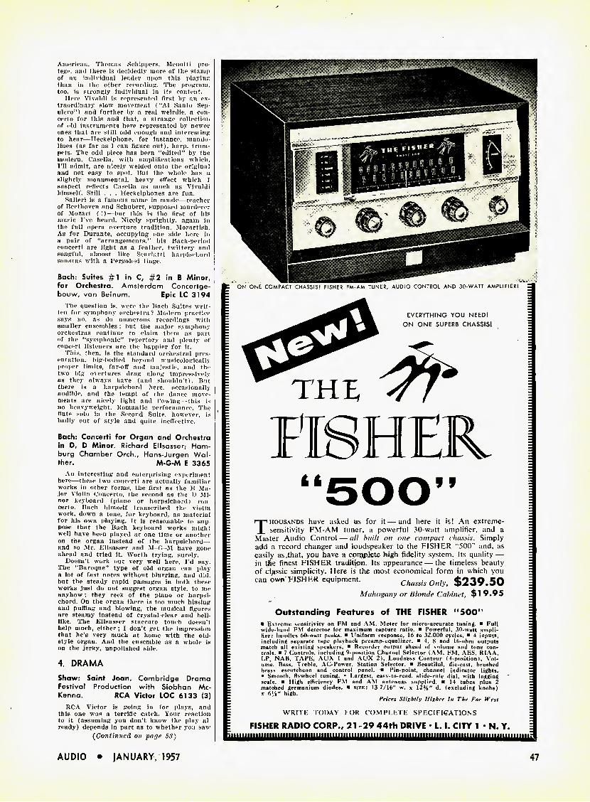
American, Thomas Schippers, Menotti pro- tege. and there is decidedly more of the stamp of an individual leader upon this playing than in the other recording. The program, too. is strongly individual in its content.
Here Vivaldi is represented first by an ex- traordinary slow movement ("Al Santo Sep- ulcro") and further by a real weirdie, a con- certo for this and that, a strange collection of old instruments here represented by newer ones that are still odd enough and interesting to hear—Heckelphone. for instance, mando- lines (as far as T can figure out), harp, trum- pets. The odd piece has been "edited" by the modern. Casella, with amplifications which, I'll admit, are nicely welded onto the original and not easy to spot. But the whole has a slightly monumental, heavy effect which T suspect reflects Casella as much as Vivaldi himself. Still . . . Heckelphones are fun.
Salieri is a famous name in music—teacher of Beethoven and Schubert, supposed murderer of Mozart ( !)—but this is the first of his music I've heard. Nicely sprightly, again in the full opera overture tradition. Mozartish. As for Durante, occupying one side here in a pair of "arrangements," his Bach-period concert! are light as a feather, twittery and songful, almost like Scarlatti harpischord sonatas with a Pergolesi tinge.
Bach: Suites #1 in C. #2 in B Minor, for Orchestra. Amsterdam Concertge- bouw, van Beinum. Epic LC 3194
The question is, were the Bach Suites writ- ten for symphony orchestra? Modern practice says no, as do numerous recordings with smaller ensembles ; but the major symphony orchestras continue to claim them as part of the "symphonic" repertory and plenty of concert listeners are the happier for it.
This, then, is the standard orchestral pres- entation, big-bodied beyond musicologically proper limits, far-off and majestic, and the two big overtures drag along impressively as they always have (and shouldn't). But there is a harpsichord here, occasionally audible, and the tempi of the dance move- ments are nicely light and flowing- -this is no heavyweight. Romantic performance. The flute solo in the Second Suite, however, is badly out of style and quite ineffective.
Bach: Concert! for Organ and Orchestra in D, D Minor. Richard Ellsasser; Ham- burg Chamber Orch., Hans-Jurgen Wal- ther. M-G-M E 3365
An interesting and enterprising experiment here—these two concerti are actually familiar works in other forms, the first as the E Ma- jor Violin Concerto, the second as the D Mi- nor keyboard (piano or harpsichord I con- certo. Bach himself transcribed the violin work, down a tone, for keyboard, as material for his own playing. It is reasonable to sup- pose that the Bach keyboard works might well have been played at one time or another on the organ instead of the harpsichord— and so Mr. Ellsasser and M-G-M have gone ahead and tried it. Worth trying, surely.
Doesn't work out very well here, I'd say. The "Baroque" type of old organ can play a lot of fast notes without blurring, and did, but the steady rapid passages in both these works just do not suggest organ style, to me anyhow ; they reek of the piano or harpsi- chord. On the organ there is too much hissing and puffing and blowing, the musical figures are steamy instead of crystal-clear and bell- like. The Ellsasser staccato touch doesn't help much, either ; I don't get the impression that he's very much at home with the old- style organ. And the ensemble as a whole is on the jerky, unpolished side.
4. DRAMA
Shaw: Saint Joan. Cambridge Drama Festival Production with Siobhan Mc- Kenna. RCA Victor LOC 6133 (3)
RCA Victor is soing in for plays, and this one was a terrific catch. Your reaction to it (assuming you don't know the play al- ready) depends in part as to whether you saw
(Continued on pope S3)
C ON ONE COMPACT CHASSIS! FISHER FM-AM TUNER, AUDIO CONTROL AND 30-WATT AMPLIFIER! -
EVERYTHING YOU NEED1 ON ONE SUPERB CHASSIS!
THE
HER
: r|nHOUSANDs have asked us for it—and here it is! An extreme- z Z sensitivity FM-AM tuner, a powerful 30-watt amplifier, and a Z - Master Audio Control — all built on one compact chassis. Simply ; I add a record changer and loudspeaker to the FISHER "500" and, as ; : easily as that. you have a compJete high fidelity system. Its quality— E ; in tfce finest FISHER tradition. Its appearance — the timeless beauty ^ - of cljissic simplicity. Here is the most economical form in which you j; i can own FISHER equipment. Chassis Only, $239.50
: Mahogany or Hlomle Cabinet, $19.95 I
: Outstanding Features of THE FISHER "500" z ■ Extreme sensitivity on FM and AM. Meter for micro-accurate tuning. ■ Full •
- wide-band FM detector for maximum capture ratio. ■ Powerful, 30-watt ampli- ; Z fier; handles 60-watt peaks. ■ Uniform response, 16 to 32.000 cycles. ■ 4 inputs, ; Z including separate tape playback preamp-equalizer. ■ 4. 8 and 16-ohm outputs Z Z match all existing speakers. ■ Recorder output ahead of volume and tone con- I Z trols. ■ 7 Controls, including 9-position Channel Selector (AM, FM, AES, RIAA, I - LP, NAB, TAPF, AUX 1 and AUX 2), Loudness Contour (4-position I, Vol- Z Z ume. Bass. Treble, AC-Power. Station Selector. ■ Beautiful, die-cast, brushed Z ^ brass escutcheon and control panel. ■ Pin-point, channel indicator lights. Z ^ ■ Smooth, flywheel tuning. ■ Largest, easy-to-read, slide-rule dial, with logging = ■ scale. ■ High efficiency FM and AM antennas supplied. ■ 14 tubes plus 2 z ■ matched germanium diodes. ■ size: 13 7/16" w. x 12%" d. (excluding knobs) z Z x 6Vi" high. z Z Prices Slightly Higher hi The Far West Z
Z WRITE TODAY FOR COMPLETE SPECIFIGATIONS z
E FISHER RADIO CORP., 21 -29 44th DRIVE • L. I. CITY 1 • N. Y.
AUDIO • JANUARY, 1957 47
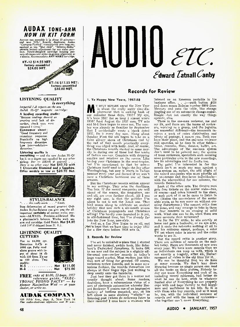
AUDIO trc.
coward Zatnall 6anb>
Records for Review
AUDAX TONE-ARM
NOW IN KIT FORM Anyone can assemble it in about 10 minutes— and save 50% ! Exactly duplicates Audax "Compass-Pivoted" transcription arm long rec- ognized as top "blue chip". "Selector-Index" permits instant adjustment for any stylus pres- sure. Newly-designed cartridge housing per- mits all-important stylus-to-groove alignment at a glance. Accommodates ANY MAKE cartridge.
KT-12 $14.55 NET; factory-assembled
$24.00 NET.
KT-16 $17.55 NET; factory-assembled
$30.00 NET.
LISTENING QUALITY is everything
Impartial I ab reports on the new Aucfak H/-Q7 magnetic cartridge: A leading recording studio; "Because readings showed an amazing total lack of dis- tortion, check tests wore repeated 3 times." Consumer sheet: "Good frequency and transient response. Practically no high frequency distortion Low inter^nodulation distortion." Listening quality is everything — and the new Audax Hi-Q7 has it to a degree not equalled by any other pickup. But — HEAR it yourself . . . there is no other way! Net $47.70 with 1 Chromatic Diamond and a Sapphire. Other models as low as $20.70 Net.
STYLUS-BALANCE . . this really works . . Canby
Stop deformation of record grooves! Onh Audax Stylus-Balance can give you the all important certainty of correct stylus prev sure—ALWAYS. Precision-calibrated likt a pharmacist's balance. Works with an) arm and cartridge. Gold Finish. Net $4.80 fadd 2^ if shipped from N. Y.).
LISTENING QUALITY CUTTERS Flat to 14,000 cps Distortion 0.6% at 1000 cps. Fully mod ulates groove with in- put of about 16 db with 220 lines. Z's up to 500 ohms. Two models: H-5 H-4
FREE cot>y "f $1-00, 22-page, 1957 reference guide, "ELEC- TRONIC PHONO FACTS" — by pioneer Maximilian Weil — at your dealer, or write us.
AUDAK COMPAQ 500 Fifth Ave.t dept. A, New York 36 F'\nf audio-flectronic appajatm vi'gr 'In \t ar *
1. Ye Happy New Yeare, 1957-58
My only remark anent the New Year is about the really nutty time-dis- placement that is making hash of
our calendar those days. 1957? My eye, it's been 1957 for so long I almost wrote 1958! Last August the 1957 cars, TV sets and hi-fi lines began to come out. The num- ber was already so familiar by September that I accidentally wrote a check dated 1957. Do it every day now. Along about October First the ads began to take on a faint silvery sheen of Christmas and by the end of that month practically every- thing was edged with holly. And, of course, the Christmas records started to come mer- rily in during one of those last fine weeks of Indian summer. Complete with dripping candles and reindeer on the covers. Like having your Christmas in the semi tropics, but I'm accustomed to that by now— Christmas itself used to begin the day after Thanksgiving, but now it starts in Indian summer every year and darned if we won't have a Christmas hurricane one of these seasons.
But the Christmas records seldom appear in my writings. They miss the deadlines. Too late. If the record companies are well ahead of the season, the magazines, one and all, are even further ahead. All I can say right now, is that the gobbler I'm about to eat is not the Xmas one. That bird comes along to celebrate an ancient holiday that now ends a six-month season of Christmas propaganda and Christmas selling! I'm hardly even launched in it yet, in old-fashioned time, but I'm already far into the New Year, new-style.
And so, a fine New Yeare to ye all, and /^et's-hope that we. have time to enjoy 1957
for a few days before 1958 sets in.
2. Records for Review I'm set to unlimbeT a piece that I started
and never finished, awhile back, like Schu- bert's Unfinished Symphony. It looks OK to me now and the subject is a slightly off- the-usual one—review records in today's huge record market. Most readers just take that sort of thing for granted. Of course, reviewers review records, and in some mys- terious fashion, the records themselves are always at their finger tips just waiting to drop neatly onto the turntable.
Just how they get there is a matter not usually thought about. Some readers, doubtless, have a subconscious vision of a sort of electronic automation whereby Rec- ord Reviewer X pushes one of an impressive battery of buttons mounted, say, at his left elbow in some shadowy "studio" or listening-post (where do reviewers listen to their records? I once knew a reviewer who
listened on an Emerson portable in his business office. . . .)—push button #26 and down comes Release number 9999 from Mercury and onto the table, like change jingling out of an automatic change-maker. Simple—but not exactly the way things operate, alas.
There is the one-man reviewer, me and my ilk, and there are the teams of review- ers, working as a group, and the logistics are somewhat different—the teamwork in- volves a pack of extra distribution and plenty of postage, I assure you. Both now have their place, and the one-man reviewer still operates, as he does in other fields—• books, concerts, films, theatre, ballet, art. The advantages of the one-man system don't need to be pointed out; the system of team reviewers, specialists each covering some particular area in the new recordings, has its advantages and its faults too.
The point I'm interested in for this month isn't so much one man against a team-system as, rather, the odd plight of the record companies who must provide all of ns—teams and free-lance individuals— with the wherewithal for our columns, the records themselves.
Look at the other arts. The theatre man gets free tickets on the center aisle—two, of course—and takes himself to the show, or such part of it as he cares to listen in on. (Hence the convenience of the center aisle seats, so he can move on without cre- ating disturbance.) The concert critic does the same, and may manage to take in three or four concerts in an evening of solid work. What else can he do, when there arc more concerts than reviewers?
As for the TV critic, he sits merrily at home and gets a backache, or an eye ache, and it costs the networks nothing at all to get his criticism except, perhaps, a color TV set where color is scarce and the critic wants to see it.
But the record critic is another story. There are millions of records on the mar- ket today. There are thousands of new ones every year. We have more records than we as individuals can keep us with, which is not exactly a tragedy, after, ill.,' Embar- rassment of riches is the old ter,m"for it.
We can be thankful that we do have so many records. We don't tear down libraries" because no single person can read all the books on their shelves. Nobody to- day can know Everything and each of us, including record reviewers, had better do what he can do best, stick to whatever limited slice of Everything he can properly cope with and hope thereby to find happi- ness and usefulness in his life. So it is with those who buy records, and so it must be, too, with the individual reviewer of records and with the team of reviewers— who together can't cover Everything.
Net $111.00 Net $75.00
48 AUDIO • JANUARY, 1957
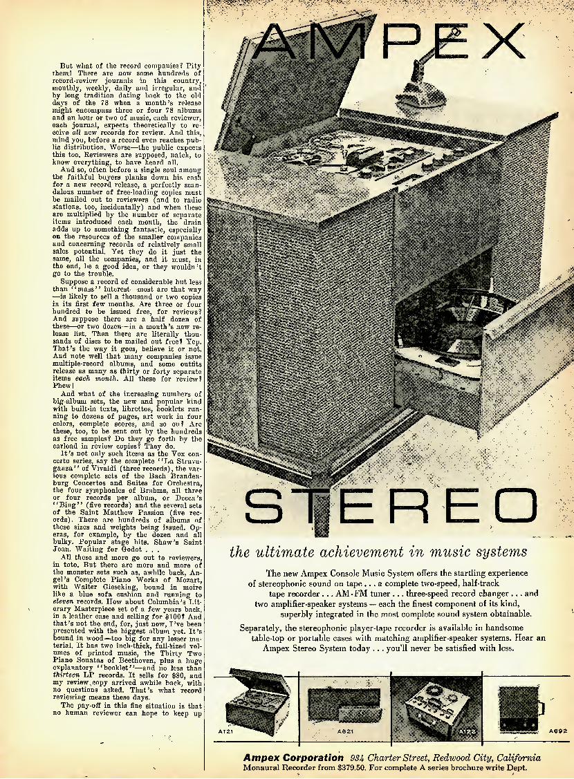
But what of the record companies? Pity them! There are now some hundreds of record-review journals in this country, monthly, weekly, daily and irregular, and by long tradition dating back to the old days of the 78 when a month's release might encompass three or four 78 albums and an hour or two of music, each reviewer, each journal, expects theoretically to re- ceive all new records for review. And this, mind you, before a record even reaches pub- lic distribution. Worse—the public expects this too. Reviewers are supposed, natch, to know everything, to have heard all.
And so, often before a single soul among the faithful buyers planks down his cash for a new record release, a perfectly scan- dalous number of free-loading copies must be mailed out to reviewers (and to radio stations, too, incidentally) and when these are multiplied by the number of separate items introduced each month, the drain adds up to something fantastic, especially on the resources of the smaller companies and concerning records of relatively small sales potential. Yet they do it just the same, all the companies, and it must, in the end, be a good idea, or they wouldn't go to the trouble.
Suppose a record of considerable but less than "mass" interest—most are that way —is likely to sell a thousand or two copies in its first few months. Are three or four hundred to be issued free, for reviews? And suppose there are a half dozen of these—or two dozen—in a month's new re- lease list. Then there are literally thou- sands of discs to be mailed out free? Yep. That's the way it goes, believe it or not. And note well that many companies issue multiple-record albums, and some outfits release as many as thirty or forty separate items each month. All these for review? Phewl
And what of the increasing numbers of big-album sets, the new and popular kind with built-in texts, librettos, booklets run- ning to dozens of pages, art work in four colors, complete scores, and so on? Are these, too, to be sent out by the hundreds as free samples? Do they go forth by the carload in review copies? They do.
It's not only such items as the Vox con- certo series, say the complete '' La Strava- ganza" of Vivaldi (three records), the var- ious complete sets of the Bach Branden- burg Concertos and Suites for Orchestra, the four symphonies of Brahms, all three or four records per album, or Decca's "Bing" (five records) and the several sets of the Saint Matthew Passion (five rec- ords). There are hundreds of albums of these sizes and weights being issued. Op- eras, for example, by the dozen and all bulky. Popular stage hits. Shaw's Saint Joan. Waiting for Godot . . .
All these and more go out to reviewers, in toto. But there are more and more of the monster sets such as, awhile back. An- gel's Complete Piano Works of Mozart, with Walter Gieseking, bound in moire like a blue sofa cushion and running to eleven records. How about Columbia's Lit- erary Masterpiece set of a few years back, in a leather case and selling for $100? And that's not the end, for, just now, I've been presented with the biggest album yet. It's bound in wood—too big for any lesser ma- terial. It has two inch-thick, full-Sized vol- umes of printed music, the Thirty Two Piano Sonatas of Beethoven, plus a huge explanatory "booklet"—and no less than thirteen LP records. It sells for $80, and my review copy arrived awhile back, with no questions asked. That's what record reviewing means these days.
The pay-off in this fine situation is that no human reviewer can hope to keep up
Ampex Corporation 93i Charter Street, Redwood City, California Monaural Recorder from $379.50. For complete A series brochure write Dept.
the ultimate achievement in music systems
The new Ampex Console Music System offers the startling experience of stereophonic sound on tape... a complete two-speed, half-track
tape recorder ... AM - FM tuner ... three-speed record changer ... and two amplifier-speaker systems — each the finest component of its kind,
superbly integrated in the most complete sound system obtainable.
Separately, the stereophonic player-tape recorder is available in handsome table-top or portable cases with matching amplifier-speaker systems. Hear an
Ampex Stereo System today . .. you'll never be satisfied with less.
A692
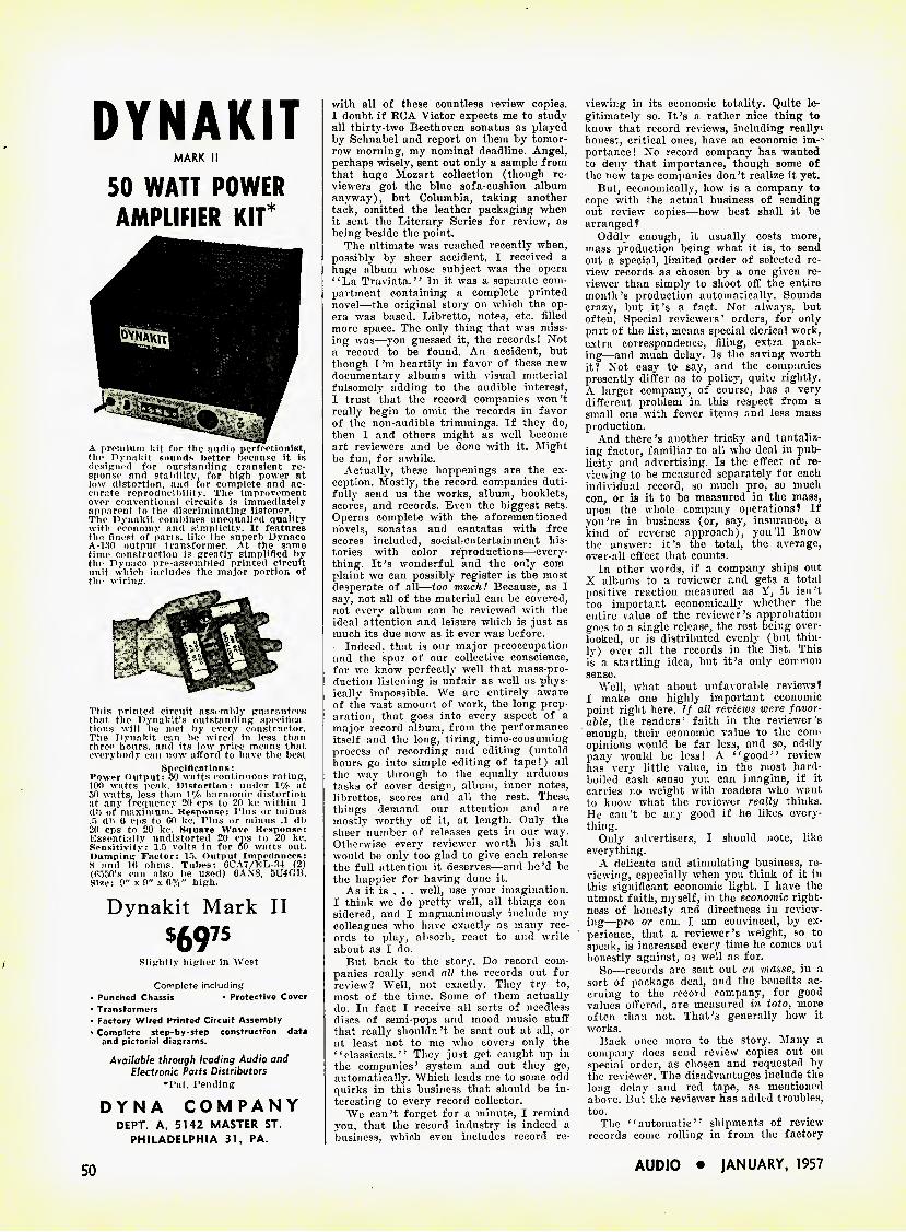
DYNAKIT
MARK II
50 WATT POWER
AMPLIFIER KIT*
A premium kit for the audio perfectionist, the Dynakit sounds hotter because it is designed for outstanding transient re- sponse and stability, for high power at low distortion, and for complete and ac- curate reproducibility. The improvement over conventional circuits is immediately apparent to the discriminating listener. The Dynakit combines unequalled quality with economy and simplicity. It features the finest of parts, like the superb Dynaco A-180 output transformer. At the same time construction is greatly simplified by the Dynaco pre-assembled printed circuit unit which includes the major portion of the wiring.
This printed circuit assembly guarantees that the Dynakit's outstanding specifica- tions will be met by every constructor. The Dynakit can be wired in less than three hours, and its low price means that everybody can now afford to have the best
8peciflcations: Power Output: 50 watts continuous rating, 100 watts peak. Distortion: under lc/c at 50 watts, less than 1% harmonic distortion at any frequency 20 cps to 20 kc within 1 db of maximum. Response: Plus or minus .5 db 6 cps to 60 kc. Plus or minus .1 db 20 cps to 20 kc. Square Wave Response: Essentially undistorted 20 cps to 20 kc. Sensitivity: 1.5 volts in for 50 watts out. Damping: Factor: 15. Output Impedances: 8 and 16 ohms. Tubes: 6CA7/RL-34 (2) (6550's can also be used) 6AX8, 5U4GB. Size: 9" x 9" x 6%" high.
Dynakit Mark II
$69" Slightly higher in West
Complete including • Punched Chassis • Protective Cover • Transformers • Factory Wired Printed Circuit Assembly • Complete step-by-step construction data
and pictorial diagrams. Available through leading Audio and
Electronic Parts Distributors ♦Pat. Pending
DYNA COMPANY DEPT. A, 5142 MASTER ST.
PHILADELPHIA 31, PA.
with all of these countless review copies. I doubt if EGA Victor expects me to study all thirty-two Beethoven sonatas as played by Schnabel and report on them by tomor- row morning, my nominal deadline. Angel, perhaps wisely, sent out only a sample from that huge Mozart collection (though re- viewers got the blue sofa-cushion album anyway), but Columbia, taking another tack, omitted the leather packaging when it sent the Literary Series for review, as being beside the point.
The ultimate was reached recently when, possibly by sheer accident, I received a huge album whose subject was the opera "La Traviata." In it was a separate com- partment containing a complete printed novel—the original story on which the op- era was based. Libretto, notes, etc. filled more space. The only thing that was miss- ing was—you guessed it, the records! Not a record to be found. An accident, but though I'm heartily in favor of these new documentary albums with visual material fulsomely adding to the audible interest, I trust that the record companies won't really begin to omit the records in favor of the non-audible trimmings. If they do, then I and others might as well become art reviewers and be done with it. Might be fun, for awhile.
Actually, these happenings are the ex ception. Mostly, the record companies duti- fully send us the works, album, booklets, scores, and records. Even the biggest sets. Operas complete with the aforementioned novels, sonatas and cantatas with free scores included, sociabentertainment his- tories with color reproductions—every- thing. It's wonderful and the only com- plaint we can possibly register is the most desperate of all—too much! Because, as I say, not all of the material can be covered, not every album can be reviewed with the ideal attention and leisure ■which is just as much its due now as it ever was before.
Indeed, that is our major preoccupation and the spur of our collective conscience, for we know perfectly well that mass-pro- duction listening is unfair as well as phys- ically impossible. We are entirely aware of the vast amount of work, the long prep- aration, that goes into every aspect of a major record album, from the performance itself and the long, tiring, time-consuming process of recording and editing (untold hours go into simple editing of tape!) all the way through to the equally arduous tasks of cover design, album, inner notes, librettos, scores and all the rest. These,, things demand our attention and are mostly worthy of it, at length. Only the sheer number of releases gets in our way. Otherwise every reviewer worth his salt would be only too glad to give each release the full attention it deserves—and he'd be the happier for having done it.
As it is . . . -well, use your imagination. I think we do pretty well, all things con- sidered, and I magnanimously include my colleagues who have exactly as many rec- ords to play, absorb, react to and write about as I do.
But back to the story. Do record com- panies really send all the records out for review? We'll, not exactly. They try to, most of the time. Some of them actually do. In fact I receive all sorts of needless discs of semi-pops and mood music stuff that really shouldn't be sent out at all, or at least not to me who covers only the " classicals." They just get caught up in the companies' system and out they go, automatically. Which leads me to some odd quirks in this business that should be in- teresting to every record collector.
We can't forget for a minute, 1 remind you, that the record industry is indeed a business, which even includes record re-
viewing in its economic totality. Quite le- gitimately so. It's a rather nice thing to know that record reviews, including really- honest, critical ones, have an economic im- portance! No record company has wanted to deny that importance, though some of the new tape companies don't realize it yet.
But, economically, how is a company to cope with the actual business of sending out review copies—how best shall it be arranged?
Oddly enough, it usually costs more, mass production being what it is, to send out a special, limited order of selected re- view records as chosen by a one given re- viewer than simply to shoot off the entire month's production automatically. Sounds crazy, but it's a fact. Not always, but often. Special reviewers' orders, for only part of the list, means special clerical work, extra correspondence, filing, extra pack- ing—and much delay. Is the saving worth it? Not easy to say, and the companies presently differ as to policy, quite rightly. A larger company, of course, has a very different problem in this respect from a small one with fewer items and less mass production.
And there's another tricky and tantaliz- ing factor, familiar to all who deal in pub- licity and advertising. Is the effect of re- viewing to be measured separately for each individual record, so much pro, so much eon, or is it to be measured in the mass, upon the whole company operations? If you're in business (or, say, insurance, a kind of reverse approach), you'll know the answer; it's the total, the average, over-all effect that counts.
In other words, if a company ships out X albums to a reviewer and gets a total positive reaction measured as Y, it isn't too important economically whether the entire value of the reviewer's approbation goes to a single release, the rest being over- looked, or is distributed evenly (but thin- ly) over all the records in the list. This is a startling idea, but it's only common sense.
Well, what about unfavorable reviews? I make one highly important economic point right here. If all reviews were favor- able, the readers' faith in the reviewer's enough, their economic value to the com- opinions would be far less, and so, oddly pany would be less! A "good" review has very little value, in the most hard- boiled cash sense you can imagine, if it carries no weight with readers who want to know what the reviewer really thinks. He can't be any good if he likes every- thing.
Only advertisers, I should note, like everything.
A delicate and stimulating business, re- viewing, especially when you think of it in this significant economic light. I have the utmost faith, myself, in the economic right- ness of honesty and directness in review- ing—pro or con. I am convinced, by ex- perience, that a reviewer's weight, so to speak, is increased every time he comes out honestly against, as well as for.
So—records are sent out en masse, in a sort of package deal, and the benefits ac- cruing to the record company, for good values offered, are measured in toto, more often than not. That's generally how it works.
Back once more to the story. Many a company does send review copies out on special order, as chosen and requested by the reviewer. The disadvantages include the long delay and red tape, as mentioned above. But the reviewer has added troubles, too.
The "automatic" shipments of review records come rolling in from the factory
50 AUDIO • JANUARY, 1957
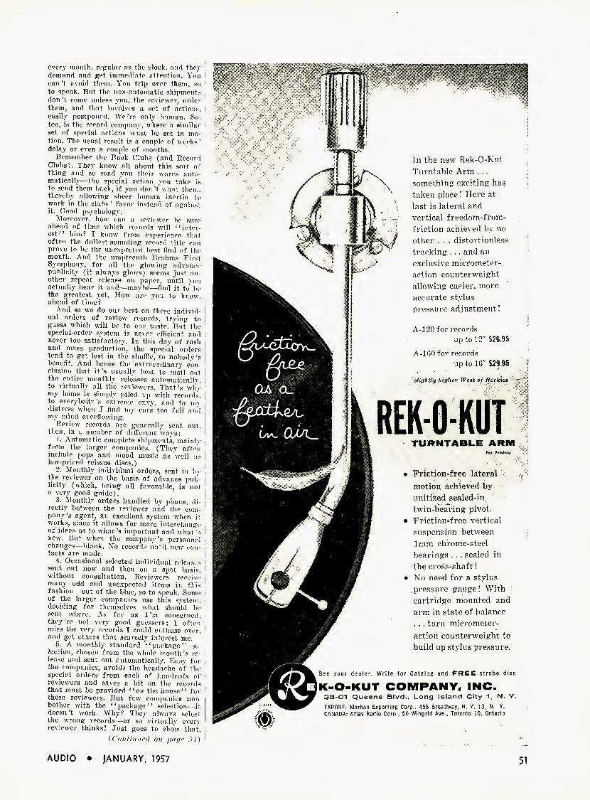
every month, regular as the clock, and thev demand and get immediate attention. Yon can't avoid them. You trip over them, so to speak. Rut the non-automatic shipments don't come unless you, the reviewer, order them, and that involves a set of actions, 1 easily postponed. We're only human. So, too, is the record company, where a similar t set of special actions must be set in mo- tion. The usual result is a couple of weeks' delay or even a couple of months.
Remember the Book Clubs (and Record Clubs). They k now nil about this sort of thing and so send you their wares auto matieally—the special action you take is to send them back, if you don't want them, thereby allowing sheer human inertia to work in the clubs' favor instead of against it. Good psychology.
Moreover, how can a reviewer be sure ahead of time which records will inter- est" him? I know from experience that often the dullest-sounding record title can prove to be the unexpected best find of the month. And the umpteenth Brahms First Symphony, for all the glowing advance publicity (it always glows) seems just an other repeat release on paper, until you actually hear it and—maybe—find it to be the greatest yet. How are you to know, ahead of time?
And so we do our best on these individ- [ ual orders of review records, trving to guess which will be to our taste. But the special-order system is never efficient and never too satisfactory. In this day of rush and mass production, the speciiil orders tend to get lost in the shuffle, to nobody's benefit. And hence the extraordinary con- clusion that it's usually best to mail out the entire monthly releases automatically, to virtually all the reviewers. That's wliy my home is simply piled up with records, to everybody's extreme envy, and to mv distress when T find my ears too full and my mind overflowing.
Review records are generally sent out, then, in a number of different ways:
1. Automatic complete shipments, mainlv from the larger companies. (They ofteii include pops and mood music as "well as low-priced reissue discs.)
2. Monthly individual orders, sent in by the reviewer on the basis of advance pub- licity (which, being all favorable, is not a very good guide).
3. Monthly orders handled by phone, di- rectly between the reviewer and the com- pany's agent, an excellent system when it works, since it allows for more interchange of ideas as to what's important and what's new. But when the company's personnel changes—blank. No records until new con- tacts are made.
4. Occasional selected individual releasrs sent out now and then on a spot basis, without consultation. Reviewers receive many odd and unexpected items in this fashion—out of the blue, so to speak. Some of the larger companies use this system, deciding for themselves what should be sent where. As far as I'm concerned, they 're not very good guessers; I often miss the very records I could enthuse over, and get others that scarcely interest me,
5. A monthly standard "package" se lection, chosen from the whole month's re- lease and sent out automatically. Easy for the companies, avoids the headache of the special orders from each of hundreds of ! reviewers and saves a bit on the records 1
that must be provided '' on the house'' for | these reviewers. But few companies now bother with the "package" selection—it doesn't work. Why? They always select the wrong records—or so virtually every j reviewer thinks! Just goes to show that,
{( 'iiilinurd on page .7 /i
f:-.
In the new Rek-O-Knt Turntable Arm . . . something exciting' has taken place! Here at last is lateral and vertical freedom-from- friction achieved by no other . . . distortionless tracking . . . and an exclusive micrometer- action counterweight allowing easier, more accurate stylus pressure adjustment !
A-l 20 for records up to 12" $26.95
A-160 for records up to 16" $29,95
slightly higher West of Roc kins
REK-O-KUT TURNTABLE ARM
Pol. Pendinq
• Friction-free lateral motion achieved by unitized sealed-in twin-bearing pivot.
• Friction-free vertical suspension between 1mm chrome-steel bearings . .. sealed in the cross-shaft!
» No need for a stylus .pressure gauge! With cartridge mounted and arm in state of balance . . . turn micrometer- action counterweight to build up stylus pressure.
See your dealer. Write for Catalog and FREE strobe disc
K-O-KUT COMPANY, INC. 38-01 Queens Blvd., Long Island City 1, N. Y. EXPORT: Morhan Exporting Corp., 458 Broadway, N. Y. 13. N, Y. CANADA: Atias Radio Corp., 50 Wingold Ave., Toronto 10, Ontario
AUDIO • JANUARY, 1957

Wonderful
1$
*
Mechanically
Coaxial Speaker
PIM SERIES Discovery of this patented principle provides super-efficient and economical means of utiliz- ing two disparate coaxlally mounted cones to divide the audio spectrum .... while both operate from a single voice coil .... a method, hitherto unattained in the history of high fidelity loudspeaker con- struction. Built-in mechanical filter between the low-frequency and high- frequency cones permits design of cone for optimum response. This provides a true coaxial two-way speaker that assures clean, ultra wide-range, wide- angle reproduction.
Model No. Dia. Response Range Max. Power PIM-6 62" 50-16,000 cps 3 watts PIM-8 8 " 40-16,000 cps 6 watts
Other Hi-Fi Speakers from the Pioneer Works :
Woofer Squawker Tweeter
4 models from 10 to 15 . 2 models 6i" cone Shorn type. 3 models 2 J" tone & horn type.
CooxialSpeaker; 4 modelsfrom 10" to 15".
HAROLD LAWRENCE
Music in the Laboratory
The house lights dim, conversation sub- sides, the pianist strides across the stage to the accompaniment of a smattering
of applause, and latecomers hurry to their seats. The hall is well attended but not one music critic has put in an appearance. His presence has been made superfluous by the machine.
The "machine" performs various func- tions simultaneously: it records the per- formance on magnetic tape, determines note accuracy, calibrates the degree of intensity with which each key is struck, and finally relates the performance to all other re- corded versions. Even before the soloist has risen to acknowledge the applause, the machine has come up with a judgment.
Science applied to music criticism could result in the above situation if a machine built by a 34-year old Polish-born pianist and Juilliard teacher named Jan Holcman were to be perfected along the lines of Univac. The purpose of Holcman's experi- ments is to establish finally an objective method of evaluating a pianist's per- formance. Many defects, as well as niceties, of technique are, states Mr. Holcman, not audible to the naked ear: symmetry of timing in a scale passage, balance of dy- namics, left and right hand coordination, etc.
Holcman's "electronic microscope" is made of the following components—two variable-speed turntables with tone arms designed to remain poised above a given groove indefinitely when necessary in order to repeat certain notes or phrases, a re- built Magnecorder tape recorder, and a control panel with a choice of 200 different combinations of inputs and outputs. With the aid of a metronome and several count- ing appliances, Holcman dissects a record- ing and compares it with other versions. By slowing its speed, he can magnify the per- formance for analytical purposes; "You see," he told Fred Grunfeld in the Satur- day Review of June 30, 1956, "at half speed you can detect technical failings that pass right by your ears in ordinary per- formance. No artist is really immune from these problems, and even the most extra- ordinary technician will show flaws under the microscope, just as the most beautiful woman will look less than perfect under a klieg light. But I'm not out just to reveal the blemishes in everybody's playing. I want to discover just what makes a great pianist, and to establish a scientific basis for teaching and criticism."
Over 1,600 records (LP's excluded—
* 26 W. Ninth Street, New York 11, N. ¥.
"Tape may be economical and efficient," Holcman explains, '' but it has robbed the record of its value as a historical document . . . by falsifying the performance.") and numerous player-piano rolls and tapes (un- spliced, of course) have been put to the test. Holcman rates Josef Hofmann as the greatest pianist if our age with Rachmani- noff, Lhevinne, Busoni, Gieseking, Tried- man, Horowitz and Landowska in second place.
Carrying Holcman's approach to other musical fields, let's examine the orchestra with the aid of the electronic ear. Orches- tral virtuosity can be gauged by precision of attack, pitch, and choir unity. At half- speed and at a higher level, such defects as a late or premature entrance, faulty in- tonation and poor bowing or blowing are plainly revealed. What appeared to be a clean tutti sforzando is, under closer ob- servation, marred by one instrument's rushed attack. This writer's experience with tape editing will testify to that. Dy- namic plateaus can also be accurately measured.
The slow-speed treatment for singers is painful for both performer and listener. It is safe to say that no singer is flattered by this process. If you want any proof of this, pick out one of your favorite vocal 78- rpm discs—and you can select an artist whose intonation is pure and whose tech- nique is free of excessive vibrato—and play it at 33% rpm. Bert Lahr at his best (or worst) couldn't approach such a sound. For some reason, male voices emerge from this ordeal most pathetically; tenors wail, weep, and groan; basses resemble weary drunks whose voices trail off: into subter- ranean caverns interspersed with occa- sional belches. Love duets heighten the effect, and the Sextet from Lucia is trans- formed into a cattle-lowing contest. How- ever, certain technical aspects of vocal pro- duction can be inspected including pitch and note oscillation—that is, if you can somehow overlook the ludicrous sounds emanating from your loudspeaker.
Various instrumental ailments can also be magnified a la Holcman: the interpo- lated glissando of the string player, a wrong note or slurred passage in a harp arpeggio, delayed damping of a triangle, kettledrum, or tam-tam, and confused cross- rhythmic sections.
The problem of maintaining a steady tempo is easily the most challenging one facing soloists, conductors, and such con- ductorless ensembles as string quartets, trios, baroque chamber groups, and so on. This can be checked, of course, without CJ)
Write for informafion to:— FUKUIN ELECTRIC WORKS, LTD.
5. Otowacho 6-chome, Bunkyo-ku, Tokyo, Japan
52 AUDIO • JANUARY, 1957
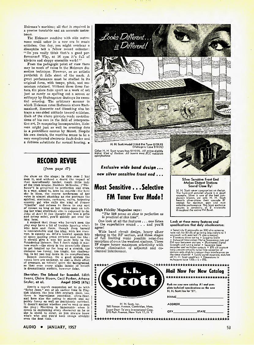
Holcman's machine; all that is required is a precise turntable and an accurate metro- nome.
The Holcman machine with side metro- nome could usher in a new era in music criticism. One day, you might overhear a discophile tell a fellow record collector: "Do you really think that's a good per- formance? Why, at 16 rpm it's full of klinkers and sloppy ensemble work!''
Prom the pedagogic point of view there may be much of value in the Holcman dis- section technique. However, as an artistic yardstick it falls short of the mark. A great performance must be studied in its original form, with tempo, pitch, and mo- mentum retained. Without these three fac- tors, the piece falls apart as a work of art just as surely as spelling out a sonnet or soliloquy by Shakespeare destroys its essen- tial meaning. The arbitrary manner in which Holcman rates Hofmann above Rach- maninoff, Horowitz and Gieseking also be- trays a one-sided attitude toward criticism. Each of the above pianists made contribu- tions of his own in the field of interpreta- tive art. In comparing incomparables, Hole- man might just as well be counting dots in a pointilliste canvas by Monet. Despite his own denials, the machine seems to be a very complicated electronic fault-finder and a dubious substitute for normal hearing. •
RECORD REVUE
(from page 47)
the show on the stage; in this case I had seen it, and without a doubt the impact of that marvellously tender, tough little lady of the Irish brogue, Siobhnn McKenna, ("She- bawn") is preserved to perfection and even, in a way, added to, here on records—for here she Is close, the coarse tenderness of her voice is almost shocking as she portrays the spirited, obstinate, cocksure, naive, bouncing country gal who calls the king of France "Charlie" and refuses to listen to any sort of reason as long as her voices keep on tell- ing her what everybody else is supposed to do. Joan of Arc ! If you thought she was a prim and prissy saint, you'll quickly get over the idea here.
I suspect that those who haven't seen the play may have a bit of trouble figuring who's who here and there, though Joan herself Is unmistakable and the king, with his stam- mer, is equally so. RCA's booklet spends lots of space quoting press reviews and the like ; it should give a wee bit more help to the floundering listener. But I don't think it mat- ters much—the story is too powerfully direct to get tangled up for long at a stretch, the dialogue too funny, too tragic, too challeng- ing, to let you bog down in its complications.
Superb recording. On a good system the voices here are uncanny, so real is their effect of presence, so velvety quiet the background, so that even every slight intake of breath is dramatically audible, however faint.
Sheridan: The School for Scandal. Edith Evans, Claire Bloom# Cecil Parker, Athene Seyler, et al. Angel 3542 [AVi)
Here's a superb companion set to go with "Saint Joan," out of an earlier time in Eng lish history, the late 18th century. Here, too. there is marvellous recording, ultra-clear, and here also the acting is superb and su- perbly funny as well as deathlessly satirical. It doesn't matter whether you've read or seen the play; Sheridan is impeccable when it comes to explaining every character as he or she is about to enter, so you always know who's who and you'll keep things straight even the first time.
Most Sensitive.. .Selective
FM Tuner Ever Made!
High Fidelity Magazine says: "The 310 seems as close to perfection as is practical at this lime".
One look at all the features . . . one listen to the superlative sound . . . and you'll agree!
Wide band circuit design, heavy silver plating in the RF section, and three stages of full limiting make possible noise-free reception of even the weakest stations. Three IF stages insure maximum selectivity with virtual elimination of adjacent and co- channel interference.
★ ■A
Silver Sensifive Front End Makes Distant Stations
Sound Close By! H. H. Scott never compromises on design. The front-end pictured above is a good example. Silver is one of the best con- ductors known, yet only H. H. Scott heavily silver-plates their cascade RF section for maximum gain and most reliable performance. This Scott exclusive assures a sensitivity of 2 microvolts throughout the entire FM Band.
Look at these many features and specifications that defy obsolescense: • Sensitivity 2 microvolts on 300 ohm antenna terminals for 20 db of auieting (eauivalent to 1 microvolt with matched 75 ohm antenna) • Planetary drive tuning • Logging Scale • Dynaural Interstation Noise Suppressor cuts out FM roar between stations • Illuminated Signal Strength and tuning meter • Separate tape recorder and multiplex outputs • 2,/2 db capture ratio permits virtually noise free reception of stations only slightly stronger than interference on the same channel • Easily panel mounted, matches all H. H. Scott amplifiers • Dimensions in mahogany case IB'/i x 5 x 9'/2.
*'★★★★★★★★★★★★★★★★★★★★★★★★★★★★★★ ★ Mail Now For New Catalog £ ★★★★★★★★★★★★★★★★★★★★★★★★★*
★ ★ ★ ★ ★ ★ ★ H H. Scott, Inc. ★ 385 Putnam Avenue, Cambridge, Mass.
Export Dept: Telesco International Corp. 270 Park Avenue, New York 17, N Y.
Rush me your new catalog Al and com- plete technical specifications on the new H. H. Scott line for '5T.
NAME
ADDRESS
city. STATE _
H. H. Scolt Model 310-B FM Tuner $159.95 (Mahogany Case $19.95)
Other H. H Scott tuners from $119.95. All prices slightly higher West of Rockies. All tuners meet FCC radiation specifications
fxc/usiVe wide band design...
new silver sensitive front end , ..
AUDIO • JANUARY, 1957 53
Amperexl
A PLUG-IN
REPLACEMENT FOR THE 12AX7
MICROPHONICS: Negligible in amplifiers requiring an input voltage of at least 50 mv for an output of 5 watts. No special precautions against microphones necessary even though the tube is mounted in the near vicinity of a loud- speaker with 5% acoustical efficiency.
HUM AND NOISE LEVEL: Better than —60 db relative to 50 mv when the grid circuit impedance is no greater than 0.5 megohms (at 60 cps), the center tap of the heater is grounded and the cathode resistor is by-passed by a capacitor of at least 100 mfd.
OTHER Amperex TUBES FOR HIGH-FIDELITY AUDIO APPLICATIONS: EL84/6BQ5 9-pin power pentode; 17 W PP 6CA7/EL34 High-power pentode; 1 00 W PP EF86/6267 Low-noise high-/x pentode ECC81/12AT7 Low-noise medium-/t dual triode ECC82/12AU7 Low-noise low-/i dual triode GZ34 Cathode-type rectifier; 250 ma. EZ80/6V4 9-pin rectifier; cathode; 90 ma. EZ81/6CA4 9-pin rectifier; cathode; 150 ma.
At All Leading Electronic Parts Distributors
Amperex ELECTRONIC CORP. 230 Duffy Ave., Hicksville, Long Island, N.Y.
Such mordant British wit, and such agile, flexible voices these people have! This is al- most an orchestrated sound of vowels and consonants, of multiple shadings and colors, subtleties of meaning, plays on words, quick repartee that floats out to you clear as dia- mond. yet as effortlessly understandable as a soap opera. An evening with Sheridan will be sheer delight. I assure you. and you'll come back to it a hundred times without tiring.
Don't I wish I'd had this kind of home work in my school English classes.
Arthur Miller, Speaking on and reading from "The Crucible/' "Death of a Sales- man." Spoken Arts (Westminster) 704
Here's an exciting and worthwhile experi- ment in combined documentary and entertain- ment—though its success will depend strictly in each recording upon the person who does the speaking and reading. Arthur Miller, quite clearly, always did want to be an actor, or so his very dramatic readings here would indicate. The record is terrific.
The only trouble with this one. you'll find after you stand on your tiptoes with suspense and anxiety for an hour or so as it plays, is that neither drama is complete, both sides feature long excerpts, just enough to get you into a state where you've just got to have the rest of the story, complete.
Miller starts off on a somewhat wrong foot, with a prepared lecture that is clearly being read ; I began to go to sleep at once, but not far enough to miss his good point about two opposite kinds of drama. It's when he gets into the plays themselves that things come to life. He reads extremely well, and gets himself so excited in the process he almost weeps with the fervor of it. Takes all the parts, male and female, and though sometimes you get a bit mixed up for a moment or two, the sense is remarkably clear and the scene utterly convincing. Whether it's the nightmar- ishly real story of witchcraft hysterical in old Salem, or the equally real and painfully true story of the New York salesman who is a failure, Arthur Miller brings it all to you.
Odd to think that this energetic intellec- tual, so preoccupied (in his plays) with petty, ugly, pathetic, horrid people who get tan- gled up in Life and can't get loose, should up and fly off with none other than La Mon- roe herself ! That's the man. Nope, she doesn't appear on this record.
And. incidentally, I wTonder how Shake- speare would have sounded if he'd had a chance to read his stuff like this. That's what Westminster wondered, and the company hopes that this series will help future genera- tions get an idea of our own men, person to person. Darned good stuff for us, right now, and especially good for schools and colleges and study groups.
Sleep No More! Famous Ghost and Hor- ror Stories read by Nelson Olmsted.
Vanguard VRS 9008 You can have this one. Maybe "few voices
are better known to the American public than that of Nelson Olmsted"—I wouldn't know, not having seen him on TV. All I know is that these readings have all the self-conscious sincerity of a good commercial and they wouldn't keep me awake ten seconds unless through sheer irritation. Faugh !
But the great American TV audience knows best and so you'd better run right out and get it. Some of the stories aren't bad, in their printed form. Dickens, Stevenson, etc. It's just the spoken form that gets me down. #
AUDIO ETC. (from page 51)
willy-nilly, you cannot judge for a record reviewer what he is going to like. Not if he's Independent-minded and respected for making his own decisions.
6. Certain naive newcomers, notably in the tape field, think that a sampling '' of the catalogue," sent once and for all, is what a reviewer wants. They mail out four
High Fidelity Amplifiers
£ icaiosti aduf
Crommes Hi-Fi Sales have doubled within the past 12 months.
/ 10PC 10 Watt Amplifier New styling and a full set of controls provides exceptional flexibility. Simple efficient compact design features mod- ern feedback circuitry, record compen- sator, loudness control, wide range bass and treble controls, rumble and scratch filters, and six inputs with one for tape head. Frequency Response: ± 0.5 DB. 20 to 20,000 CPS. Distortion: 2% harmonic and 3% intermodulation at 10 watts. In charcoal gray and brass.
Net Price 57.50
2 15PG 12 Watt Amplifier The all new deluxe 15PC features the most advanced feedback circuitry, the highest quality components and greater flexibility of controls. It provides sep- arate turnover and roll-off record com- pensators, new loudness control, wide range bass and treble controls, rumble and scratch filters, and six inputs in- cluding tape head. Frequency Response: ± 0.5 DB. 20 to 30,000 CPS. Distortion: 1 % harmonic and 2% intermodulation at 12 watts. In charcoal gray and brass.
Net Price 69.50
3 20PC 20 Watt Amplifier An all new amplifier with all the fea- tures of the deluxe 15PC plus higher power in the output stage. Frequency Response: ± 0.5 DB. 15 to 30,000 CPS. Distortion: 1% harmonic and 2% in- termodulation at 20 watts. In charcoal gray and brass. Net Price to user 89.50
See the "Best Buy in Hi-Fi" at your High Fidelity Dealer or write
Grommes Div. of Precision Electronics, Inc.
Dept. A-l, 9101 King St., Franklin Park, III.
□ Send Free Hi-Fi Equipment Brochure
Name Street City Zone . . . State
BEST BUY
54 AUDIO • jANUARY, 1957
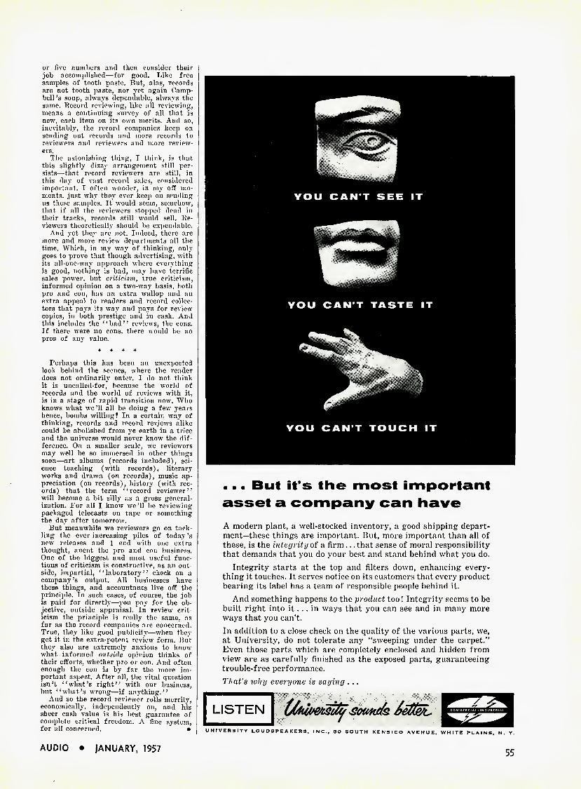
or five numbers and then consider their job accomplished—for good. Like free samples of tooth paste. Rut, alas, records are not tooth paste, nor yet again Camp- bell's soup, always dependable, always the same. Record reviewing, like all reviewing, means a continuing survey of all that is new, each item on its own merits. And so, inevitably, the record companies keep on sending out records and more records to reviewers and reviewers and more review- ers.
The astonishing thing, T think, is that this slightly dizzy arrangement still per- sists—that record reviewers are still, in this day of vast record sales, considered important. I often wonder, in my off mo- ments, just why they ever keep on sending us these samples. It would seem, somehow, that if all the reviewers stopped dead in their tracks, records still would sell. Re- viewers theoretically should be expendable.
And yet they are not. Indeed, there are more and more review departments all the time. Which, in my way of thinking, only goes to prove that though advertising, with its all-one-way approach where everything is good, nothing is bad, may have terrific sales power, but criticism, true criticism, informed opinion on a two-way basis, both pro and con, has an extra wallop and an extra appeal to readers and record collec- tors that pays its way and pays for review copies, in both prestige and in cash. And this includes the 4'bad" reviews, the cons. If there were no cons, there would be no pros of any value.
* * * *
Perhaps this has been an unexpected look behind the scenes, where the reader does not ordinarily enter. I do not think it is uncalled-for, because the world of records and the world of reviews with it, is in a stage of rapid transition now. Who knows what we'll all be doing a few years hence, bombs willing? In a certain way of thinking, records and record reviews alike could be abolished from ye earth in a trice and the universe would never know the dif- ference. On a smaller scale, we reviewers may well be so immersed in other things soon—art albums (records included), sci- ence teaching (with records), literary works and drama (on records), music ap- preciation (on records), history (with rec- ords) that the term '' record reviewer'' will become a bit silly as a gross general- ization. For all I know we '11 be reviewing packaged telecasts on tape or something the day. after tomorrow.
But meanwhile we reviewers go on tack- ling the ever-increasing piles of today's new releases and I end with one extra thought, anent the pro and con business. One of the biggest and most useful func- tions of criticism is constructive, as an out- side, impartial, '' laboratory'' check on a company's output. All businesses have these things, and accountants live off the principle. In such cases, of course, the job is paid for directly—you pay for the ob- jective, outside appraisal. In review crit- icism the principle is really the same, as far as the record companies are concerned. True, they like good publicity—when they get it in the extra-potent review form. But. they also are extremely anxious to know what informed outside opinion thinks of their efforts, whether pro or eon. And often enough the eon is by far the more im- portant aspect. After all, the vital question isn't "what's right" with our business, but "what's wrong—if anything."
And so the record reviewer rolls merrily, economically, independently on, and his sheer cash value is his best guarantee of complete critical freedom. A fine system, for all concerned. •
AUDIO • JANUARY, 1957
... But it's the most important
asset a company can have
A modern plant, a well-stocked inventory, a good shipping depart- ment—these things are important. But, more important than all of these, is the integrity of a firm... that sense of moral responsibility that demands that you do your best and stand behind what you do.
Integrity starts at the top and filters down, enhancing every- thing it touches. It serves notice on its customers that every product bearing its label has a team of responsible people behind it.
And something happens to the product too! Integrity seems to be built right into it. .. in ways that you can see and in many more ways that you can't. In addition to a close check on the quality of the various parts, we, at University, do not tolerate any "sweeping under the carpet." Even those parts which are completely enclosed and hidden from view are as carefully finished as the exposed parts, guaranteeing trouble-free performance. That's tvhy everyone is saying ...
UNIVERSITY LOUDSPEAKERS, INC., SO SOUTH KENSICO AVENUE. WHITE PLAINS, N. Y.
55
{IAoiMJM SAMS:
AUDIO BOOKS:
HI-FI HANDBOOK This new book by William F. Boyce provides comprehensive information for audiophiles and technicians interested in Hi-Fi design, selection and installation. Chapters cover; Fidelity, Sound Theory and Distortion; Loud- speakers; Baffles and Enclosures; Amplifiers. Preamplifiers and
Controls; Program Source Equipment; Systems Design, Selection and Installation. Really covers the subject, with invaluable hints on equipment selection, operation of program sources, speaker location and system installation. 240 pages; 5l/i \ S'/i"; fully illustrated. .
THE RECORDING AND REPRODUCTION OF SOUND Oliver Read's popular best-seller; favorably reviewed by leading authorities on audio. Widely used by sound engineers, audiophiles, public address technicians, broad- casting stations, recording studios and audio students. Authoritative chapters cover: behavior of sound
waves; basic recording methods; the decibel; phono reproducers; cutting styli; microphones; loudspeakers and enclosures; amplifiers; AM and FM tuners; home music systems; public address systems—plus hundreds of other sub- qt jects. Illus.; 810 pages; 6x9"; hard cover
TAPE RECORDERS; HOW THEY WORK Gives you an expert understand- ing of tape recording. Explains magnetic recording theory; de- scribes characteristics of tape; tells how a recorder operates; dis- cusses motorboard mechanism, drive motors, volume indicators, bias oscillators, equalization cir-
cuits, amplifiers and magnetic heads. Tells you how to get best frequency response, how to avoid overload, how to obtain best bias settings; in- cludes procedures for testing recorders yj- and tape. 176 pages; illus.; SVixS'/z" J
ATTENUATORS,EQUALIZERS AND FILTERS Thoroughly describes design, application and theory of opera- tion of every type of Attenuator, Equalizer and Wave Filter. Covers equalization and attenuation used in audio recording and reproduc- ing systems, both professional and home-type. Includes chapter on
Hi-Fi crossover networks. Provides time-saving charts which permit the easy determination of component values required in designing equalizers and filters. Indispensable to technicians in radio, television and cinema work, and to audiophiles. 176 pages; S'/i x S'/i"; hard cover; illustrated ^'f.UU
PUBLISHED BY ,. HOWARD W. SAMS & CO., INC... Order from any Radio & TV Parts Distributor, • or mail to Howard W. Sams & Co., Inc., ^ Dept. 20-A7, 2201 E. 46th St., Indianapolis 5, Ind. # Send books checked below. $ enclosed * □ Hi-Fi Handbook ($3.00) □ Tape Recorders ($2.75) • □ Recording & Reproduction of Sound ($7.95) # □ Attenuators, Equalizers & Filters ($4.00) • • Name — * Address _ City _State_
ACOUSTICAL CONSIDERATIONS
{from page 24)
like others of its kind, could be brought to equal maximum response with the rest of the system only with a theoretical 1200 watts of driver power; it was, there- fore, obvious that larger amplifiers would accomplish little beyond the possible de- struction of the speakers during the per- formance. Figure 5 is a block schematic of the entire system.
Bell System Laboratories studies had suggested to us that 30-watts-per-chan- nel should be adequate to reproduce the full symphony, with loudspeaker sys- tems of 50 per cent efficiency, with the ex- ception that bass drum peaks might over- load the amplifiers. In the last analysis, then, the efficiency at the frequency ex- tremes, of any loudspeaker which might have been selected imposed the system's frequency-response limitations.
Preparation During the rehearsal week before the
concert, experiments were made with a small body of observers toward the pos- sibility of employing two-channel rather than three-channel stereophonic trans- mission. It could not be doubted that the three-channel system produced reproduc- tion more nearly resembling the live orig- inal than did two-channel transmission. It is of especial interest, however, that the three-channel tapes, upon review in a much smaller auditorium, of nearly ideal acoustical characteristics, could be shown to have negligible advantage over two- channel tapes. In this corollary experi- ment, switching apparatus was devised so that, in one position, the three channels were separately presented, while in a second instantaneously available posi- tion, identically the same over-all level of sound was presented through two stereophonic channels, the output of the former center channel being mixed equally into each of the two separate outer channels. With a succession of audiences, consisting of trained musi- cians, engineers concerned with audio subjects, and lay individuals, no signifi- cant accuracy could be found in judg- ments of the distinction.
Conclusions
Measurements of the acoustical dis- persion of sound in the War Memorial Opera House auditorium established that the difference in sound level, during live performances in various parts of the auditorium, did not exceed about 3 db. A much larger difference occurred, how- ever, during reproduction: differences existing simultaneously at various parts of the auditorium were the order of 7 db. It is submitted that this must be ex- plained by the large difference which exists between the ratio of direct to re- verberated sound between live orchestra and loudspeaker-radiated sounds. Each loudspeaker radiates substantially equal power into a vertical angle of 45 deg. and, a horizontal angle of 90 deg.; in live performance the instruments indi- vidually possessed varying radiation pat- terns. In the A/B comparisons afforded by the second carefully observed section of the concert, especially, it became evi- dent that both the ratio of string energy to wind instrument energy was distorted in the reproduction, and that the char- acter of the sound from these disparate kinds of instruments was subtly altered, in a manner which suggested that, in the reproduction, string sounds received by the audience were disproportionately direct instead of reverberated, while sounds from the more directional wind instruments, in reproduction, possessed an unnaturally large proportion of re- verberant energy. It is believed that this difference, more than any other, pro- vided the most immediately discernable distinction between live and reproduced sound, upon close comparison. A second, and only rarely observable distinction could be made by the presence of low- level tape hiss during silent or very soft orchestral passages. •
i This paper was originally presented by Mr. Snyder to the International Congress on Acoustics, under the auspices of the Acoustical Society of America, at the Mas- sachusetts Institute of Technology, Cam- bridge, Massachusetts, June 22, 1956.
56 AUDIO • JANUARY, 1957
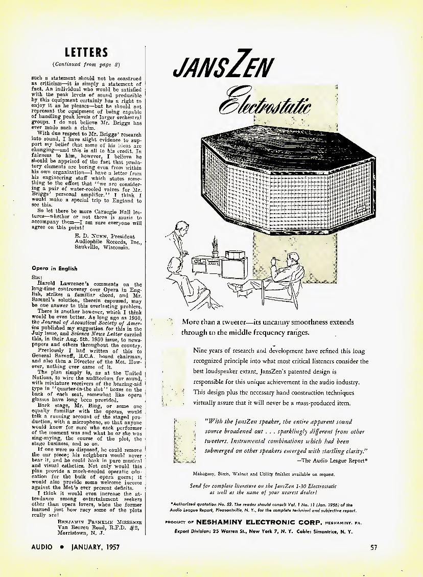
LETTERS {Continued from page 8)
such a statement should not be construed as criticism—it is simply a statement of fact. An individual who would be satisfied with the peak levels of sound producible by this equipment certainly has a right to enjoy it as he pleases—but he should not represent the equipment of being capable of handling peak levels of larger orchestral groups. I do not believe Mr. Briggs has ever made such a claim.
With due respect to Mr. Briggs' research into sound, I have slight evidence to sup- port my belief that some of his ideas are changing—and this is all to his credit. In fairness to him, however, I believe he should be apprised of the fact that preda- tory elements are boring even from within his own organization—I have a letter from his engineering staff which states some- thing to the effect that "we are consider- ing a pair of water-cooled valves for Mr. Briggs' personal amplifier." I think I would make a special trip to England to see this.
So let there be more Carnegie Hall lec- tures whether or not there is music to accompany them—I am sure everyone will agree on this point!
E. D. Nunn, President Audiophile Records, Inc., Saukville, Wisconsin.
Opera in English Sir:
Harold Lawrence's comments on the long-time controversy over Opera in Eng- lish, strikes a familiar chord, and Mr. Samuel's solution, therein espoused, may be one answer to this everlasting problem.
There is another however, which I think would be even better. As long ago as 1950, the Journal of Acoustical Society of Amer- ica published my suggestion for this in the July issue, and Science News Letter carried this, in their Aug. 5th. 1950 issue, to news- papers and others throughout the country.
Previously I had written of this to General Sarnoff, R.C.A. board chairman, and also then a Director of the Met. How- ever, nothing ever came of it.
The plan simply is, as at the United Nations, to wire the auditorium for sound, with miniature receivers of the hearing-aid type in "quarter-in-the slot" boxes on the back of each seat, somewhat like opera glasses have long been provided.
Back stage, Mr. Bing, or some one equally familiar with the operas, would talk a running account of the staged pro- duction, with a microphone, so that anyone would know for sure who each performer of the moment was and what he or she was sing-saying, the course of the plot, the stage business, and so on.
If one were so disposed, he could remove the ear piece; his neighbors would never hear it, and he could bask in pure musical and visual esthetics. Not only would this plan provide a much-needed operatic edu- cation for the bulk of opera goers; it would also provide some welcome income against the Met's ever present deficits.
I think it would even increase the at- tendance among entertainment seekers other than opera lovers, when the former learned just how racy some of the plots really are!
Benjamin Franklin Miessner Van Beuren Road, R.F.D. #2, Morristown, N. ,1.
jansZen
More than a tweeter—its uncanny smoothness extends
through to the middle frequency ranges.
Nine years of research and development have refined this long
recognized principle into what most critical listeners consider the
best loudspeaker extant. JansZen's patented design is
responsible for this unique achievement in the audio industry.
This design plus the necessary hand construction techniques
virtually assure that it will never be a mass-produced item.
"With the JansZen speaker, the entire apparent sound
source broadened out . . . sparklingly different from other
tweeters. Instrumental combinations which had been
submerged on other speakers emerged with startling clarity."
u —The Audio League Report*
Mahogany, Birch, Walnut and Utility finishes available on request.
Send for complete literature on the JansZen 1-30 Electrostatic as well as the name of your nearest dealer!
0Authorized quotation No. 52. The reader should consult Vol. 1 No. 11 (Jan. 1956) of the Audio League Report, Pleasantville, N. Y., for the complete technical and subjective report.
PRODUCT OF NESHAMINY ELECTRONIC CORP. NESHAM.NY, PA Export Division: 25 Warren St., New York 7, N. Y. Cable: Simontrice, N. Y.
AUDIO • JANUARY, 1957 57
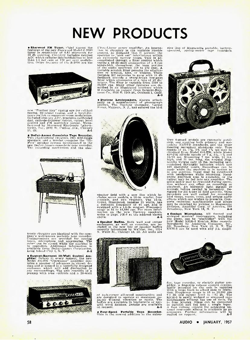
NEW PRODUCTS
• Sherwood FM Tuner. Chief among the features of the new Sherwood Model S-3000 tuner is sensitivity of 0.95 microvolt for 20 dh ouieting. Circuitry includes delayed AGC which reduces intermodulation to less than 1.5 per cent at 100 per cent modula- tion. Other features of the S-3000 are the
new "Feather Ray" tuning" eye for critical tuning, fly-wheel tuning, and a local-dis- tance switch to suppress cross modulation. Included also are AFC, precision calibrated dial, cathode-follower outnut, output level control and FM multiplex output. Manu- factured by Sherwood Electronic Labora- tories, Inc., 2S02 W. Cullom Ave., Chicago IS, 111. A-l • DeJur-Amsco Consolette Tape Recorder. Two electrostatic tweeters, two mid-range speakers, and a woofer comprise the "Hi- Five" speaker system incorporated in the new DeJur-Amsco consolette tape recorder. The recording mechanism and the elec-
tronic circuitry are identical with the com- pany's well-known portable tape recorder. Compartments are provided for storing tapes, microphone and accessories. The cover can be closed while the machine is in operation. Additional information is available from DeJur-Amsco Corporation, Long Island City 1, N. Y. A-2 • Sargent-Rayment 20-Watt Control Am- plifier. Deluxe in every respect, the new Model SR-200 "Claremont" amplifier con- tains a number of advances in circuit de- sign and is housed in a tastefully designed enclosure which will add distinction to any surroundings. The unit consists of a preamp with tone controls and a 20-watt
sive line of Magnemite portable, battery- operated, spring-motor tape recorders.
Two 4-speed models are currently avail- able, one meeting both primary and sec- ondary NARTB standards, and the other meeting secondary standards only. Tape speeds of 15, T1^, 3% and 1T4 ips may be obtained from Model 610-EM, while Model 610-DM affords speeds of T1/^, 3%, 1% and 15/16 ips. Measuring 7 ins. wide, 10 ins. high, and 11 ins. long, the 4-speed Mag- nemite weighs only 15 lbs. including self- contained flashlight batteries which last 100 operating hours. Recordings can be made while the machine is in motion or in any position. Input may be monitored with headphones while recording. Head- phone playback also is available, or the output may be fed into any amplifier. The drive motor may be rewound during opera- tion without any effect on recording or playback. An indicator light signals 30 seconds before rewind is necessary. De- signed for all types of field activity, these recorders are well suited for recording bird songs, music, voice, and unique audio effects which one wishes to preserve. Com- plete technical specifications and prices may be obtained by writing to Magnemite Division, Amplifier Corp. of America, 398 Broadway, New York 13, N. Y. A-6 • Contact Microphone. All fretted and stringed musical instruments, including the piano, can be "electrified" with the new Model KKH-3 Kontak Mike recently introduced by Amperite Company, Inc., 561 Broadway, New York 12, N. Y. The KKH-3 can be used with any p.a. ampli-
L'ltra-Linear power amplifier. An innova- tion in circuitry is the variable rumble control, so designed that it permits the operator to "pick out" interference within an extremely narrow range. This is ac- complished through a filter control which varies a 40-db-deep attenuation of a 5-cps bandwidth throughout the bass portion of the audio spectrum (19 to 122 cps). A variable scratch filter permits the elimina- tion of scratch, hiss, or whistle. Three variable RC networks in gang with 14 db feedback provide a sharp-break low-pass filter which attenuates at a rate of IS db/ octave. The filter is variable from 2400 to 30,000 cps. Many other features are de- scribed in an illustrated brochure which is available on request from Sargent-Rav- ment Co., 4926 E. 12th St., Oakland 1, Calif.
A-3
speaker field with a new line which in- cludes seven models, a 15-in. woofer, four coaxials, and two tweeters. The 12-in. Royal, illustrated, handles 25 watts, has a resonant frequency of 4 5 cps, and is equipped with a 1.5-lb. magnet. Frequency range is 35 to IS,000 cps. For more infor- mation on the new Duotone speakers, write to Dept. PR-S at the address shown above. A-4 • Speaker Baffles. Both wall and corner enclosures, as well as consoles, are in- cluded in the new line of speaker baffles recently introduced by Wellcor, Inc., 1214 X. Wells St., Chicago 10, 111. All units are
• Duotone Loudspeakers. Known princi- pally as a manufacturer of phonograph needles. The Duotone Company, Locust Street, Keyport, N. J., has entered the hi-fi
of lock-corner all-wood construction and are designed to operate at maximum ca- pacity without vibration or rattle. The baffles are available in leatherette or nat- ural wood finishes. Details are available on request. A-5 • Tour-Speed Portable Tape Recorder. This is the newest addition to the exten-
fier, tape recorder, or electric guitar am- plifier. A fingertip volume control conven- iently mounted on the unit is supplied with a large knob to afford ease of opera- tion. Frequency range is 40 to 10,000 cps ± 2 db and output level is — 55 db. The KKH-3 is easily wedged or strapped onto instruments without the use of tools. Up to four Kontak Mikes can be connected in parallel and fed into a single input. A foot volume control for achieving un- usual crescendo effects is available as an accessory. Further information will be mailed on request. A-7
58 AUDIO • JANUARY, 1957

HARVEY HI-FI
January-February, 1957
The new year abounds with promise to the sound fancier, veteran or tyro.The best available high-fidelity equipment is being brought to a peak of refinement unthinkable only a few years ago; the more modestly priced components are beginning to reflect the full benefit of the advanced engineering thinking that originally went into the price-no-object models: long-playing records, prerecorded tapes and FM broadcasts are rapidly approaching virtual freedom from distortion; and stereophonic sound is moving out of the luxury category. The picture is at least as gratifying to HARVEY's, the store that fostered this coming of age of high fidelity, as it is to the prospective purchaser. We are celebrating our 30th birthday this year and we feel that the following equipment is worthy of launching the anniversary season:
The most original of the late developments is undoubtedly the Audax tone-arm kit. In answer to the obvious demand for a top-quality transcription pickup arm at a genuinely low price, Audak's veteran audio wizard Maximilian Weil re-engineered the celebrated Audax HF compass-pivoted" arm to such a degree of structural simplicity that it could be packaged
as a fool-proof kit and was even further improved in performance. The resultant KT-12 and KT-16 twelve and sixteen-inch arms cost nearly 50% less in kit form than factory-assembled and can be put together in a matter of 10 or 20 minutes by anyone who can handle a small screwdriver without cutting himself. The completed kits are indistinguishable from the factory jobs, and the design itself is as good as any high-fidelity enthusiast can ask for. The KT-12 kit sells for S14 55, the KT-16 kit fdr $17.55. (S24.00 and S30.00, respectively, when purchased factory-assembled.)
When a high-fidelity amplifier of such superior design as the Mclntosh C-8 and MC-30 combination have been on the market for several years without the slightest necessity of modification, it requires little "selling" to the knowledgeable audiophile. However, it should be pointed out to those who have had no opportunity to work with this beautiful eguipment that the C-8 audio compensator, for example, has five separate push-button switches for bass turnover compensation and five similar switches for treble de-emphasis. These switches work not only one by one but also cumulatively, so that the number of available equalization curves is nearly infiinite. This is only one feature of the C-8's tremendous front-end versatility. As for the MC-30 power amplifier, it incorporates the patented Mclntosh output circuit with unity coupling and Fimply performs up to its rated maximum power of 30 watts as any Mclntosh amplifier should and does-with close to zero distortion. Price of the C-8 is S88.50 (without cabinet); of the MC-30, S143.50.
In this age of automation, the Miracord XA-100 three-speed automatic record changer is deservedly famous as just about the last word in push-button convenience. Load it with 10-inch and 12-inch records, intermixed in any sequence. Push one button and it starts. Push another and it stops, the arm going back to rest position. Push still another and the entire record or just a portion of the record is repeated. Push an entirely separate button and a filter goes into action to screen out the surface noise. Push the fifth button and you get a predetermined pause between records. Or quickly switch spindles and you have a manual record player. Very gentle on the record, too, and just $67.50.
When audio perfectionists discuss "ultimate" systems, the JBL Signature 'Hartsfield' speaker system, by James B. Lansing Sound, Inc., is certain to be among the very first components mentioned. This mighty instrument was designed with only one goal in mind—verbatim translation into sound waves of the electrical signal dictated by the amplifier, regardless of cost. The 'Hartsfield' is characterized by the utmost simplicity and ruggedness. There is only one crossover —right in the center of the audible spectrum, at 500 cps. The bass comes from a true exponential folded horn, built with the same care as a concert grand piano and driven by a rigid, straight-sided 15-inch cone with 4-inch voice coil. The treble driver weighs 31 pounds and is terminated by a huge straight horn with a 20-inch acoustical lens. The sound is as good as the specifications and the price—you have to pay for the best — is $732.00.
Audio connoisseurs on a budget who must have the best without giving up eating, should hear the Acoustic Research AR-2 speaker system. This is the spectacular small brother of the already famous AR-1, which gave a complete reverse twist to loudspeaker design by proving that smooth, undistorted bass down to 30 cps and lower could be produced out of a 2 cubic foot box. The AR-2 is even smaller (only I3V2" x 24" x 113s"), utilizes the same "acoustic suspension" principle for bass reproduction, and sacrifices only the last few cycles on the bottom end. It is still reasonably efficient at 30 cycles and requires less amplifier power than the AR-I. The newly developed treble speaker is also very smooth and sweet, and the price-best surprise of all-is only $96.00.
Don t forget about HARVEY's mail order department! Just enclose an extra allowance for shipping charges (excess will be promptly refunded) and let us ship your order the same day as we receive it.
HARVEY RADIO CO., INC. 1123 Avenue of the Americas {6th Ave. at 43rd St.), New York 36, N.Y. JUdson 2-1500
AUDIO • JANUARY, 1957 59

n EONARD RADIO. INC. T«Hi 7. N. T. COftlon* 7-031$
NOW it can be told . . .
20% discount from popular ad- vertssad prices on all Stereophonic Tape as listed in discount schedule listed belsw.
FREE CLUB MEMBERSHIP
with
INITIAL ORDER OF
3 OR MORE
STEREOPHONIC TAPES
NO "EXTRA" CHARGES
All orders shipped from STOCK within 48 hours
Brand list-
A-V Tape 9.95 Concert Hall
1200' 11.95 1800' 17.90 3000' 23.90 3600' 23.90
HIFI Tapes 12.95 Livingston
Atlantic Audiosphere Boston Esoteric 1 1.95
RCA Victor "C" Series 10.95 "D" Series 1 2.95 "E" Series 14.95 "F" Series 16.95 "C" Series 18.95
Stereotape Demo Tape Halt Reel 7.95 Full Reel 11.95
Other Brands In Stock At Popular Advertised Prices
Sonotape Concertapes Omegatapes Alphatapes
Jazztapes
Mail orders filled. 25% deposit bal- ance C.O.D. Add. 15 cents postage for each reel up to 6 reels. 7 or more reels add flat $1.00.
Club Membership Coupon: Name ■ Address
City Zone . , . State .... I own a □ Stacked □ Staggered tape playback □ recorder □. A157
Free monthly flyer listing all new re- leases to club members.
Circle 60A
MORE ABOUT HUM
{from page 25)
It was then found that balance of the a.e. hum output with changing of the plug could be obtained with the common circuit of Fig. 1. The amplifier was built on a steel chassis instead of alu- minum as had been used for prior units, so naturally, a.c. fields were given special consideration. Originally, the 115-volt a.c. supply wiring was arranged as illus- trated at (A) in Fig. 3. It can be seen that the supply leads, power transformer leads, and turntable motor leads were twisted together only for a portion of their total length. In Fig. 3, (B) shows a revised method of running all 115-volt a.c. leads, whereby each pair is twTisted together continuously up to the point of connection. This method of dressing the a.c. leads did the trick and the circuit of cither Figs. 1 or 2 could be used with equal results. With either circuit the variation in hum level when "turning over" the a.c. power plug amounted to no more than 2 db and the hum was sufficiently low.
The writer has arrived at a conclusion concerning the undesirable condition but is not entirely satisfied with it. The reader may have some ideas concerning this problem and his suggestions will be welcomed.
"STANDARD" SPEAKER
(from page 35)
the two sound outputs, then check by listening to male voices on the complete system. Optimum results can be obtained without instruments if necessary, and the lack of them need not deter anyone from assembling a satisfactory system. It is suggested, however, that after de- ciding upon the correct position and phasing for the high-frequency speaker, this position be marked carefully. Then, live with the system for a week or so before making the mounting permanent. Try shifting the unit back and forth while listening to a familiar record or program. Make sure that the optimum position is determined before the job is considered complete.1
TV Receiver Placement
The entire superstructure was planned to house the Tech-Master kit receiver, since this model has an excellent repu- tation for performance. Other models can undoubtedly be fitted into the space
1 See '' Observations on loudspeakers,'' Audio, November, 1956, p. 65.
Report from the
LABORATORY
Zke Audio Ccague Report * Fig. 5 Acoustic Output at 30 CPS
AR-1W The League's ref- erence standard
15" speaker y system -A.
12" speaker system JL
15" speaker ry system Li
•Vo/. 1 No. 9, Oct., '55. Authorized quotation #28. For the complete technical and subjective report on the AR-J consult Vol. 1 No. 11, The Audio League Report, Pleasantville, N. Y.
Report from the
WORLD of MUSIC
The Aeolian-Skinner Orgao Co. uses an AR woofer (with a Janszen electrostatic tweeter) in their sound studio. Joseph S. Whiteford, vice- pres., writes us:
"Your AR-1W speaker has been of inestimable value in the production of our re- cording series 'The King of instruments'. No ether system I have ever heard does justice to the intent of our recordings. Your speaker, with its even bass line and lack of distortion, has so closely approached 'the truth' that it validates itself immediately to those who are concerned with musical values/'
AR speaker systems (2-way, or woof- er-only) are priced from $132 to $185. Cabinet size 14" x 11%" x 25"; suggested driving power 30 watfs or more. Illustrated brochure on request.
ACOUSTIC RESEARCH, INC. 24 Thorndike St., Cambridge 41, Mass.
Circle 60B
YOUR PRICE
7.99
9.56 14.32 19.12 19.12 10.36
9.56
8.76 10.36 1 1.96 13.56 15.16
2.00 6.36 9.56
60 AUDIO • JANUARY, 1957
if desired, and the particular method of placement is left to the ingenuity of the individual constructor.
Connections to the picture-tube socket should be made through a 5-prong socket and plug, and those for the focus and deflection coils should be made with an octal socket and plug. It is necessary to carry a ground connection to the brack- ets which mount the two coils so as to have a ground for the outside coating of the tube, as well as for protection during adjustments. For the high-volt- age connection, it is suggested that a banana jack be installed on the Bake- lite insulating strip where the lead nor- mally leaves the high-voltage compart- ment. This permits the chassis to be re- moved for servicing without unsoldering any connections.
The focus coil and the deflection yoke are mounted on the hand-hole cover in the tube compartment, using the original bracket modified to mount on the slop- ing surface. The tube is centered in the compartment, with padding all around for protection. The leads are brought up through notches along the side of the tube compartment cover. A plastic mask is mounted on a %-in. oak veneer front panel, providing both protection for the face of the tube and masking for the picture tube.
Woodwork Finishing
In the cabinet shown, the front and tops are oak veneered, treated in the blond "rift" finish. This is a simple oper- ation, consisting solely of painting the well-sanded oak surface with one coat of Firzite, allowing it to dry for about five minutes, and then wiping it off. The white remains in the grain of the wood and gives it an attractive finish. After the paint dries for about 24 hours it may be waxed, or else several coats of shellac may be used, rubbing each down with steel wool. Since there are so many methods of finishing wood, this part of the work may well be left to the dis- cretion of the builder.
The speaker well, the sides, and the edges of the tops are lacquered with two coats of ensign blue Larcoloid, which gives a glossy finish from a brush coat.
This particular treatment may not appeal to everyone, but it is modern and attractive, and requires a minimum of work. Since the entire design is es- sentially modern, it is felt that the sur- face treatment should also be modern.
After the cabinet is completed, it can be permanently installed as previously outlined. Two rings are mounted at the sides of the tube compartment. To these are attached 8-in. lengths of chain, which are connected in turn to 4-in. turn- buckles. Another length of chain is at- tached to the other end of each turn- buckle, and looped as closely as pos-
TRUE HIGH FIDELITY BEGINS
with a
WEATHERS
FM PICKUP
SYSTEM
ONLY with a Weathers Pickup can yoo enjoy full- range true fidelity sound reproduction. The moving mass and motional impedence of the stylus force are so low, it reproduces full-recorded range without tearing the delicately engraved record grooves.
You can increase your record effectiveness by thou- sands of plays by using a Weathers FM pickup system—the most significant Hi-Fi achievement for the record collector and discriminating music lover.
Hearing is believing. Ask your dealer to demonstrate a Weathers Pickup.
2(Jedthm\ Division of
Barrlngton,
ubm. 'Ultrasonic Corp.^
New Jersey
the ONLY
PICKUP
DESIGNED
for a
stylus force
of ONE GRAM!
• Follows every recorded detail faithfully with- out damaging delicate record engravings.
• Widest f reque ncy range response.
• Lower distortion than anything previously known.
• A sapphire stylus lasts a 1000 plays longer —a diamond stylus forever/
TAPE RECORDERS
AND
TAPE RECORDING
By
Harold D. Weiler Author of
"High Fidelity Simplified"
The first complete book for the home recordist. Tells why, how, and what in easily understood language—not too technical, yet technically accurate. Covers sound, room acoustics, micro- phones, microphone techniques, editing and splicing, sound effects and how to make them, maintenance, and adding sound to slides and home movies.
RADIO MAGAZINES. INC., Book Division P. 0. Box 629, Mineola, N. Y.
Please send me copies of Weiler's TAPE RECORDERS AND TAPE RE- CORDING. I enclose check □ money order □. □ Board cover, $3.95, □ paper cover, $2.95.
Name Address
City Zone State
TAPE RECORDERS AND
TAPE RECORDING | ^ 1 c®
1 I CkJ in
\ ii-l r
Is/'"
1^X1 I Harold D 1 WEILER
AUDIO • JANUARY, 1957 61

Are you Boom Conscious?...
Most people know by this time that many, if not most, loudspeaker enclosures . . . re- gardless of size or price . . . boom. Boom is that dull, heavy, toneless thud often heard at low frequencies. Boom is also called "one-note bass" or "juke box bass." It is an inherent characteristic of so-called ■"resonant" enclo- sures. Boom is nothing but distortion, and any speaker system that booms is not high fidelity.
Notwithstanding this, and believe it or not, there are still people who will spend hundreds, and even thousands, of dollars for prime ampli- fiers, tuners, etc.. and then go out and buy a boom-box. Why?
A noted psychiatrist undertook to find the answer. He found that (1) some people mistake mere loudness (so-called "augmented" bass) for true bass; (2) others are unable to tell the difference between true bass and boom; (3) some think boom is bass; (4) others think boom is bass because it comes from large and/or expensive enclosures; (5) others have a fixation for expiring myths, such as, ''the bigger the box the better the sound"; (6) some innately resist progress and never seem able to adjust themselves to better things as they come along; (7) others are impressed by
expensive advertising and high-pressure sales promotion.
And so it goes, even though, actually, no one ever heard boom from a live orchestra. And since a live orchestra is not a boom-box, why should anyone want a boom-box in his home? Fortunately, no one has to buy a boom- box.
To those who want live-music facsimile in- stead of boom, competent sound engineers un- equivocally recommend THE BRADFORD PERFECT BAFFLE. IT DOES NOT BOOM . . . EVER. The result is clean, true bass. This is accomplished by a new, patented device based upon a scientific principle. It is not a bass-reflex or folded horn.
Moreover, it satisfies every other criteria of the discriminating audiophile: Compactness; 12" X 12" X 9" for 8s and 10s; 17" x 17" x 14" for 12s and 15s. Finest Construction and Finish; 94", genuine mahogany, korina blond, walnut and ebony veneers; and unfinished birch. Econ- omy; from $34.50 to $69.50.
If you are boom conscious, want live-music facsimile instead of those dull, heavy, toneless thuds, hie to your dealer or write for litera- ture.
sible over a large screw hook inserted in the floor right in the corner of the room. The turnbuckles are then tight- ened up, sealing the top against the wall. Originally it was planned to use a steel cable, but the difficulty of attaching the hooks and turnbuckles to the cable ruled it out after a few trials. The chain is much simpler. It may be desirable to deaden the chain with a cloth sleeve over it, or by lacing venetian-blind cord through the links. The gasket used for the top is a 5/16-in. braided clothesline, tacked on the ends and glued into the groove for its entire length. The sides of the cabinet are spaced from the wall by ordinary door stops—adjusted to the required IVa in. by selecting the point at which they are attached to the cab- inet. Actually, there does not seem to be a noticeable difference in performance if the cabinet is not perfectly airtight to the corner.
Performance
Subjectively, this speaker system seems to be "the answer," in the opinion of the writer and of many others who have heard it. It gives the feeling of a wide source of sound, as would be ex- pected since the separation between low- and high-frequency speakers is approx- imately 33 inches from center to center, and the very low frequencies come from the side vents. The over-all width of the speaker from wall to wall on the plane of the front is (55 inches. This wide- source effect is pleasant in the extreme and until it is experienced, the listener may doubt its advantages. A similar ef- fect may be obtained for a trial by con- necting two or three speakers to the output of an amplifier, and placed about this distance apart.
The efficiency of the low-frequency speaker is evaluated by comparing the setting of the high-frequency attenuator with that used when the identical com- ponents were assembled in a T1/^ cu- ft- bass reflex cabinet of conventional de- sign, as they were prior to building this unit. With the old cabinet, balance was obtained with fi db in the h.f. attenuator, while only 4 db is required with the corner speaker. This indicates that the low-frequency speaker is 2 db more ef- ficient in this cabinet than it was with the bass-reflex box.
Performance of this system compares favorably with medium-size theatre sys- tems. and it has "presence"—the in- tangible characteristic of realism which gives the desired feeling that the per- former is actually in the room.
Late Modification
Since this enclosure was first built in 1948, no changes have been made in the original design except for the addition of a "super-tweeter" high-frequency unit and its associated dividing network
BRADFORD & COMPANY, 27 East 38th Street, New York 16, N. Y.
~J{,eep informed—read
ELECTRONIC MUSICAL
INSTRUMENTS
By
Richard H. Dorf
In one big volume, you can now learn all about the intricacies of commercial electronic organs, including the Allen, Baldwin, Conn- sonata, Hammond, Minshall-Estey, Lowrey Organo, and others, together with many smaller instruments. Constructional details on the author's Electronorgan and the simpler Thyratone show you how to build one of these fascinating instruments for yourself. A compilation in book form of the author's articles in Radio Electronics, brought up to date and with many additions. Price $7.50 (Foreign, $8.00).
Customary discounts to dealers and distributors
RADIO MAGAZINES, INC., Book Division P. O. Box 629, Mineola, N. Y.
Please send me copies of Dorf's ELECTRONIC MUSICAL INSTRU- MENTS. I enclose check □ money order □ for $7.50 each (Foreign, $8.00).
Name Address City Zone State
u
62 AUDIO • )ANUARY, 1957
and level control. The speaker itself is mounted on the left side and the level control on the right, being located slightly above the center of the narrow panel of parts (9) and (10) shown in Fig. 8. The 4000-cps dividing network is enclosed in a small metal case and is mounted on the back of the tube-cover plate, which covers the cutout in part (A) of Fig. 4. This location is conven- ient, but would depend somewhat on the size and type of midrange unit em- ployed.
Altogether, the design is sufficiently flexible to permit the use of cone tweet- ers, horns of various sizes, or any other high-quality components which may be selected. For example, the model shown in Fig. 5 employs a 1 x 4 multicellular horn and a super-tweeter, both being located behind the grille shown at the top of the front panel. One modifica- tion of this type of cabinet consists in placing a 90-deg. "V" behind the woofer with the two panels extending from the bottom to the top and placed as close to tiie speaker unit as possible. This is quite effective if the front horn is elim- inated, with the woofer being mounted directly on the front panel.
We have not seen fit to make any changes from the original (except for the super-tweeter) and to date we do not believe that we have heard any other complete speaker system designed for the home that excels this one. Those that have come close have almost always been of the same general type of design, but this may be attributed to a certain degree of coloration to which we are accustomed and which we now think of as being "the way it should sound." However, most others who have heard this particular system have gone away with the feeling that this one was out- standingly good—in fact, one listener was described as "having stars in his eyes."
The system has stood the test of time —eight years, so far—and we have no hesitancy in recommending its construc- tion to those interested in making their own. We believe that the results will more than justify the time and money expended. •
TAPE RECORDER AMPLIFIER
(from page 19)
phone jack, Consequently when a phone plug carrying the signal from a tuner, audio control unit, or the like is inserted into J2, Vj is cut out of the cir- cuit. Noise and hum produced by the F, stage are thus eliminated, improving the signal-to-noise ratio obtained on radio input.
On radio input the volume control presents a load impedance of 0.25 meg.
,
v .• • - '■ > •' : ' ^ >' ^slightly higher west of the Mississippi
! :■ I -XO - ^ H ; -y V v .'V -i^L
write for literature
• | f K ^ V ' V;M ' n ■ ' :/ r H-V,! '•< > , -->V;
marantz company
44-15 Vernofl Boulevard, Long Island City 1, N. Y.
CIRCLE 63 A },: .;,i i >
Twenty-four leading phono pickups have now been tested by The Audio League. The ESL Professional and Concert Series remain in first place.
These Audio League tests show that ESL electrodynamic cartridges are tops in smoothness, clarity, and naturalness of reproduction.*
In addition, record and stylus life are greatly extended by the ESL, which in this way saves the purchaser many times its own cost.
Join the musicians, engineers, and music lovers who have switched to the world's most advanced cartridge. Write for details and, even better, hear the difference at your dealer's.
FOR LISTENING A T S BEST
Electro-Sonic Laboratories, Inc.
Dept. A. 55-54 Thirty-sixth Street • Long Island City 6, N.Y.
Soloist Series from $14.95 • Concert Series $35.95 • Professional Series arm and cartridge $106.50
* Authorized quotation So. 57. Please consult The Audio League Report. Vol. 1, No. 6-7 (March-April tq$s) for the complete technical and subjective report. Subscription: 1 2 issues $4. from P. O. Box 262, Mf. VernoH, N. Y.
CIRCLE 63 B
AUDIO • JANUARY, 1957 63
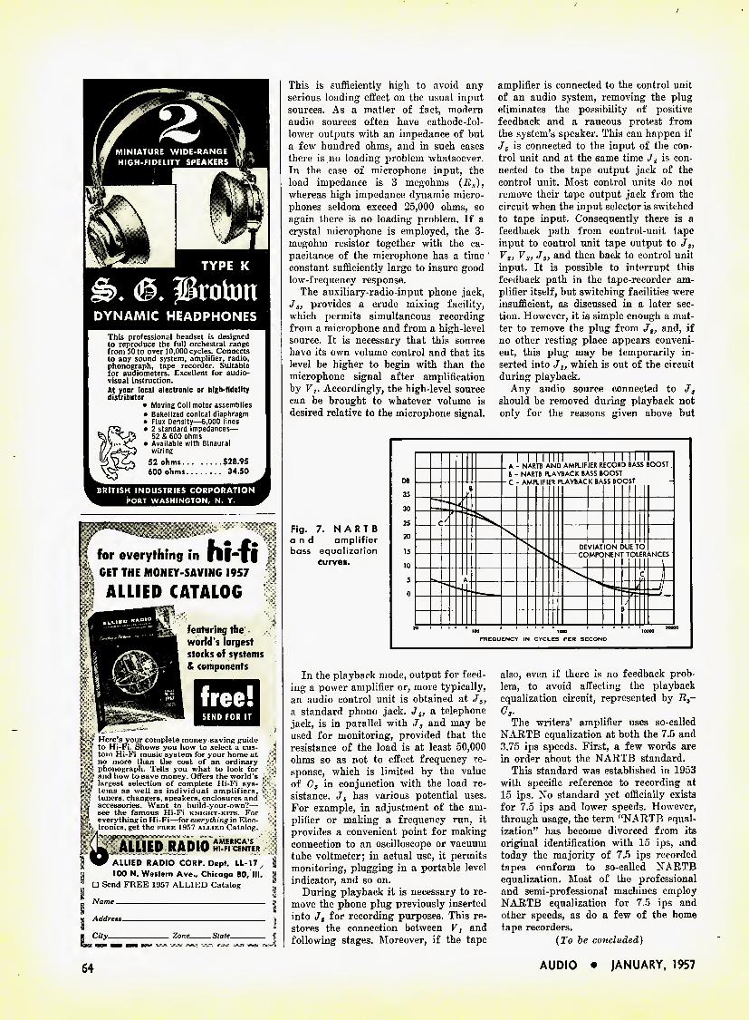
TYPE K
DYNAMIC HEADPHONES
This profession?! headset is designed to reproduce the full orchestral range from 50 to over 10,000 cycles. Connects to any sound system, amplifier, radio, phonograph, tape recorder. Suitable for audiometers. Excellent for audio- visual instruction. At your local electronic or high-fidelity distributor
• Moving Coil motor assemblies • Bakelized conical diaphragm • Flux Density—6,000 lines • 2 standard impedances—
52 & 600 ohms • Available with Binaural
wiring 52 ohms $28.95 600 ohms 34.50
BRITISH INDUSTRIES CORPORATION PORT WASHINGTON, N. Y.
This is sufficiently high to avoid any serious loading effect on the usual input sources. As a matter of fact, modern audio sources often have cathode-fol- lower outputs with an impedance of but a few hundred ohms, and in such cases there is no loading problem whatsoever. In the case of microphone input, the load impedance is 3 megohms (R3), whereas high impedance dynamic micro- phones seldom exceed 25,000 ohms, so again there is no loading problem. If a crystal microphone is employed, the 3- megohm resistor together with the ca- pacitance of the microphone has a time constant sufficiently large to insure good low-frequency response.
The auxiliary-radio-input phone jack, Js, provides a crude mixing facility, which permits simultaneous recording from a microphone and from a high-level source. It is necessary that this source have its own volume control and that its level be higher to begin with than the microphone signal after amplification by Fj. Accordingly, the high-level source can be brought to whatever volume is desired relative to the microphone signal.
Fig. 7. NARTB and amplifier bass equalization
curvet.
amplifier is connected to the control unit of an audio system, removing the plug eliminates the possibility of positive feedback and a raucous protest from the system's speaker. This can happen if J5 is connected to the input of the con- trol unit and at the same time ./2 is con- nected to the tape output jack of the control unit. Most control units do not remove their tape output jack from the circuit when the input selector is switched to tape input. Consequently there is a feedback path from control-unit tape input to control unit tape output to J3, Vt, V3, J5, and then back to control unit input. It is possible to interrupt this feedback path in the tape-recorder am- plifier itself, but switching facilities were insufficient, as discussed in a later sec- tion. However, it is simple enough a mat- ter to remove the plug from Jg, and, if no other resting place appears conveni- ent, this plug may be temporarily in- serted into J,, which is out of the circuit during playback.
Any audio source connected to J, should be removed during playback not only for the reasons given above but
In the playback mode, output for feed- ing a power amplifier or, more typically, an audio control unit is obtained at J5, a standard phono jack. J4, a telephone jack, is in parallel with J5 and may be used for monitoring, provided that the resistance of the load is at least 50,000 ohms so as not to effect frequency re- sponse, which is limited by the value of C5 in conjunction with the load re- sistance. Jl has various potential uses. For example, in adjustment of the am- plifier or making a frequency run, it provides a convenient point for making connection to an oscilloscope or vacuum tube voltmeter; in actual use, it permits monitoring, plugging in a portable level indicator, and so on.
During playback it is necessary to re- move the phone plug previously inserted into J2 for recording purposes. This re- stores the connection between F, and following stages. Moreover, if the tape
also, even if there is no feedback prob- lem, to avoid affecting the playback equalization circuit, represented by R5- C,.
The writers' amplifier uses so-called NARTB equalization at both the 7.5 and 3.75 ips speeds. First, a few words are in order about the NARTB standard.
This standard was established in 1953 with specific reference to recording at 15 ips. No standard yet officially exists for 7.5 ips and lower speeds. However, through usage, the term "NARTB equal- ization" has become divorced from its original identification with 15 ips, and today the majority of 7.5 ips recorded tapes conform to so-called NARTB equalization. Most of the professional and semi-professional machines employ NARTB equalization for 7.5 ips and other speeds, as do a few of the home tape recorders.
(To be concluded)
free! SEND FOR IT
Here's your complete money-saving guide to Hi-Fi. Shows you how to select a cus- tom Hi-Fi music system for your home at no more than the cost of an ordinary phonograph. Tells you what to look for and how to save money. Offers the world's largest selection of complete Hi-Fi sys- tems as well as individual amplifiers, tuners, changers, speakers, enclosures and accessories. Want to build-your-own?— see the famous Hi-Fi knight-kits. For everything in Hi-Fi—(or everything in Klec- tronics.get the free 1957 allied Catalog.
D A mft AMERICA'S RADIO HI-FI CENTER ALLIED RADIO CORP. Dept. LL-17 100 N. Western Ave.f Chicago 80, III.
□ Send FREE 1957 ALLIED Catalog Name
Address-
City Zone State—
featuring the world's largest stocks of systems & components
hi-fi for everything in
GET THE MONEY-SAVING 1957
ALLIED CATALOG
A - NARTB AND AMPLIFIER RECORD BASS BOOST_ B - NARTB PLAYBACK BASS BOOST C - AMPLIFIER PLAYBACK BASS BOOST
DEVIATION DUE TO "COMPONENT TOLERANCES
64 AUDIO • JANUARY, 1957
AUDIO AMPLIFIERS
{f mm page 21)
values of the time constants of the vari- ous stages. Thus in the case of a three- time-constant circuit if we design so that one of the time constants is ap- proaching 90 deg. when the other two are just past 45 dog., let us say one cir- cuit at 80 deg. and two at 50 deg., we will have system which will allow the application of 20 db of feedback with almost 10 db of safety margin.
Since the Williamson type amplifler is a very popular type, let us study it in detail. An analysis of the circuit in Fig. 4 shows that it has three time con- stants at low frequencies—two 7iC cou- pling circuits and the output trans- former; therefore we should be able to maintain low frequency stability with 20 db of feedback.
Because it is much easier to obtain response at low frequencies by the use of BC circuits than by means of trans- formers it is evident that we should have the longer time constants in the RC cou- pled stages. We should try to approach a 10-to-l ratio between the time constant of at least one of the RC stages and the transformer primary inductance-plate to plate load combination. Such a long RC constant is difficult to obtain in the out- put stage of the Williamson since the output tubes are operated at a high plate dissipation which requires that the grid leak resistors be kept low in value to prevent the tubes from running away from the effects of ion currents or grid emission. The size of the coupling capaci- tors is similarly limited by the consider- ations of leakage and physical size. The time constant in the output grids is made about 1/40 sec. and the constant of the driver grid circuit is made about 1/8 sec. Exact calculations on the low-fre- quency characteristics of the amplifier are complicated by the fact that the pri- mary inductance of the output trans- former may change appreciably with a change of signal level; therefore, the time constant of the transformer will change with signal level.
At very high frequencies the problem of insuring stability is much more com- plicated because we have five time con- stants to deal with, two of which are tied to the characteristics of the output transformer. Even if it were easily pos- sible there would be no advantage of making all the other time constants shorter than those of the transformer, since it is possible that the transformer alone could give 180 deg. phase shift before the gain around the feedback loop was reduced to one. It is therefore
COMtHO to your city
HIGH FIDELITY MUSIC SHOWS
See and hear the latest in HIGH FIDELITY from leading high fidelity manufacturers . . .
Don't miss these public showings of Hi-Fi Equip- ment . . . from the most economical units for the budget-minded to spectacular home music theatres . . . compare and enjoy them all. Components and complete systems will be displayed.
THREE DAYS OF CONTINUOUS DEMONSTRATIONS 1 P.M. to 10 P.M.
Minneapolis-St. Paul Detroit Cleveland Pittsburgh Baltimore Seattle Portland, Ore. Cincinnati Miami St. Louis
January 11, 12, 13 February 1, 2, 3 February 22, 23, 24 March 8,9, 10 March 22, 23, 24 August 23, 24, 25 September 6, 7, 8 September 20, 21, 22 October 18, 19, 20 November 22, 23, 24
Dyckmann Hotel Statler Hotel Hollenden Hotel Penn-Sheraton Hotel To be announced To be announced To be announced Sheraton-Gibson Hotel McAllister Hotel Statler Hotel
RigO Enterprises, Inc. SCO North Dearborn Street, Chicago 10, Illinois
66 E. Gloucester Pike, Barrlngton, New Jersey
Export: Joseph Plasencia, Inc., 401 Broadway, New York 13, N. Y.
for Realism, Beauty, Comp
• An Integrated acoustical system with full range natural reproduction ■■ ■• . ' • i . ,;S: • Engineered to produce extraordinary presence, clean dynamics and transients,
voice reproduction with startling realism. : ' • : v m | • Cabinets finished by master craftsmen.
• All done by the same technical magic which produced the world's finest phonograph pickup ... the famous WEATHERS FM 1-gram pickup.
*?eical for limited space: Weight 43 lbs., only 8%" deep, 32" long, and 26" high.
"Jfat: Natural Mahogany $135.00, Blonde $139.50. Write for full information.
AUDIO • JANUARY, 1957 65
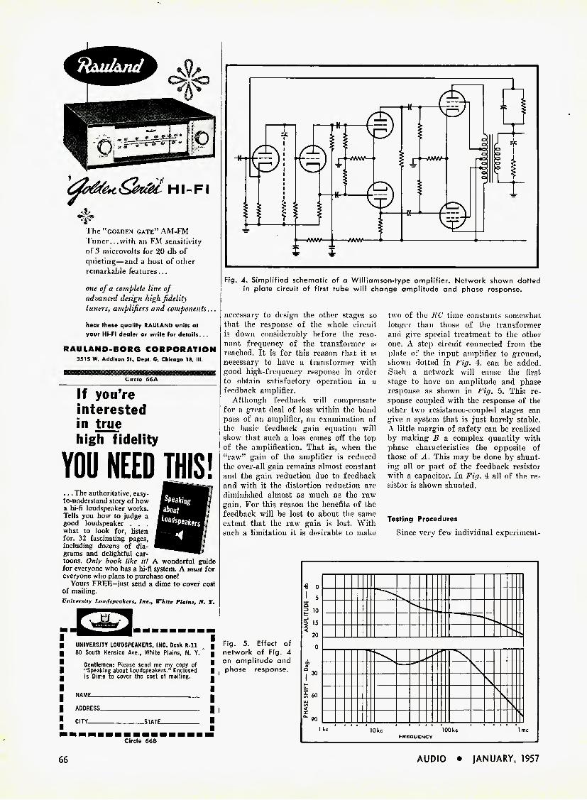
ffaul&ju/
The "golden gate" AM-FM Tuner...with an FM sensitivity of 3 microvolts for 20 db of quieting—and a host of other remarkable features...
one of a complete line of advanced design high fidelity tuners, amplifiers and components...
hear these qualify RAULAND units at your Hi-Fi dealer or write for details. . .
RAULAND-BORG CORPORATION 3515 W. Addison St., Dept. G, Chicago 18, III.
Circle 66A
If you're
interested
in true
high fidelity
YOU NEED THIS!
Speaking about
... The authoritative, easy- to-understand story of how a hi-fi loudspeaker works. Tells you how to judge a good loudspeaker . . . what to look for, listen for. 32 fascinating pages, including dozens of dia- grams and delightful car- toons. Only book like it! A wonderful guide for everyone who has a hi-fi system. A must for everyone who plans to purchase one!
Yours FREE-just send a dime to cover cost of mailing. University Loudspeakers, Inc., White Plains, N, Y.
Fig. 4. Simplified schematic of a Williamson-type amplifier. Network shown dotted in plate circuit of first tube will change amplitude and phase response.
necessary to design the other stages so that the response of the whole circuit is down considerably before the reso- nant frequency of the transformer is reached. It is for this reason that it is necessary to have a transformer with good high-frequency response in order to obtain satisfactory operation in a feedback amplifier.
Although feedback will compensate for a great deal of loss within the band pass of an amplifier, an examination of the basic feedback gain equation will show that such a loss conies off the top of the ainpliflcation. That is, when the "raw" gain of the amplifier is reduced the over-all gain remains almost constant and the gain reduction duo to feedback and with it the distortion reduction are diminished almost as much as the raw gain. For this reason the benefits of the feedback will be lost to about the same extent that the raw gain is lost. With such a limitation it is desirable to make
two of the 7?C time constants somewhat longer than those of the transformer and o'ive special treatment to the other one. A step circuit connected from the plate of the input amplifier to ground, shown dotted in Fit/. 4, can be added. Such a network will cause the first stage to have an amplitude and phase response as shown in fiff. 5. This re- sponse coupled with the response of the other two resistance-coupled stages can give a system that is just barely stable. A little margin of safety can be realized by making li a complex quantity with phase characteristics the opposite of those of A. This may be done by shunt- ing all or part of the feedback resistor with a capacitor. In Fit/. 4 all of the re- sistor is shown shunted.
Testing Procedures
Since very few individual experiment-
UNIVERSITY LOUDSPEAKERS, INC. Desk R-n 80 South Kensico Ave,, White Plains, N. Y.
Gentlemen: Please send me my copy of "Speaking about Loudspeakers." Enclosed is Dime to cover the cost of mailing.
NAME.
Fig. 5. Effect of network of Fig. 4 on amplitude and phase response.
ADDRESS- CITY _STATE_
Circle 66B
66 AUDIO • jANUARY, 1957

Fig. 6. 'Scope pattern showing ringing on 10,000-cp5 square wave.
ers or hobbyists who build audio finipli- fiers have phase meters or access to them and very few have audio oscillators with a range of 1 to 100,000 ops, the preced- ing information is of interest mainly for background purposes. With the mini- mum equipment which one should have available in order to adjust high-fidelity
Fig. 7. When small capacitor is added across output circuit, oscillation increases.
systems the practical aspects of the sta- bility problem can be worked out. This minimum of equipment consists of an audio oscillator which produces sine and square waves at frequencies up to 10,000 cps and an oscilloscope which will dis- play these waveforms. Most oscilloscopes have response up to 100,000 cps and arc thus adequate to reproduce a 10,000 cps square wave. An oscilloscope with a slow sweep speed of about two seconds is very useful for the investigation of the low- frequency response of the amplifier to transients, but essentially the same in- formation can be obtained by watching a meter needle or a speaker cone when transients arc fed into the amplifier. If only a sine wave oscillator is available a simple clipper can be built to change the sine waves to square waves.
Once an amplifier is finished it should be turned on with a resistance load con- nected to the terminals and the feedback loop disconnected. An oscilloscope should
be connected across the load and the audio oscillator connected to the input of the amplifier. The oscillator should be adjusted to furnish a small signal and the oscilloscope should be set up so that a trace of a convenient size is visi- ble on the screen. Next the feedback net- work should be connected. If the ampli- tude of the trace on the 'scope screen is reduced you have everything hooked up correctly. If the amplifier goes into vio- lent oscillation at some medium fre- quency it is necessary to reverse either the primary or the secondary leads of the output transformer. If instead of achieving a reduction of height of the trace when the transformer connections are correct you get very high frequency oscillations you have an amplifier which is unstable with the amount of feedback used and the amount of feedback should be reduced until steps are taken to in- crease the stability of the amplifier.
It may also happen that the amplifier is unstable at low frequencies which will be evidenced by motorboating whicli may either be spontaneous or be depend- ent upon being initiated by some tran- sient. In this case also the amount of feedback should be decreased until the amplifier is stable so that means of in- creasing the margin of stability can be explored.
Taking the high-frequency troubles first; after stability has been restored by decreasing feedback a 10,000-cps square wave should be applied to the input of the amplifier. The wave form shown on the oscilloscope will be likely to have the appearance of Fig. 0 which shows violent ringing on the top of the 10,000-cps square waves. A .005 M-f ca- pacitor connected across the load resistor gives the waveform shown in Fig. 7. The capacitor lowers the resonant frequency of the output and thereby reduces the stability of the amplifier. Figure 7 shows that the amplifier is almost in continu- ous oscillation. When the step circuit
Vita! Facts
TONE ARMS
In his new book, HI-FI GUIDE,* Donald Carl Hoefler, internationally famous au- thority on sound engineering, says this about the ORTHO-SONIC V/4 tone arms:
"One of the newest and most revolution- ary, on the other hand, is the Or^hosonic V/4. This is the commercial realization of an idea which is as old as recordmg itself. "Engineers have been attempting unsuc- cessfully for many years to perfect an arm which will move the reproducing stylus in a straight line across the record, this being the path followed by the original cutting stylus. When the playback does not occur along this path there is said to be tracking error . . . "The design problems here are obvious. In addition to straight-line movement, it is essential that this movement be virtually frictionless. And it was this latter re- quirement that most designers have had to admit defeat. Now, however, the de- velopers of the Orthosonic claim to have licked the problem, and the preliminary evidence would indicate that the claims are well founded. If so, they have abso- lutely nothing to worry about. If it lives up to its promise, the Orthosonic arm will make pivoted tone arms as dead as the dodo bird." Ortho-Sonic V/4 solves the problem; it permits the stylus to ride the center of the groove; makes old records sound like new; preserves record life and stylus wear!
MODEL #100 (12" size) $35.95 MODEL #200 (Transcription) .... $44.50 MODEL #300 (Binaural) $59.50 Leading hi-fi. dealers everywhere now demon- strate the ORTHO-SONIC V/4. Ask for it, or write to us for descriptive literature.
REDDI-SWEEP Indispensable Hi-Fi Record Brush
SAVES RECORD and STYLUS LIFE
Complete $4.95
Fig. 8. Addition of network of Fig. 4 re- duces ringing appreciably.
ORTHO-SONIC INSTRUMENTS, Inc. I 66 B Mechanic Street, New Rochelle, N. Y. I
* MECHANICS ILLUSTRATED, Hi-Fi Guide, Published by Fawcett Publications, Inc.
AUDIO • JANUARY, 1957 67
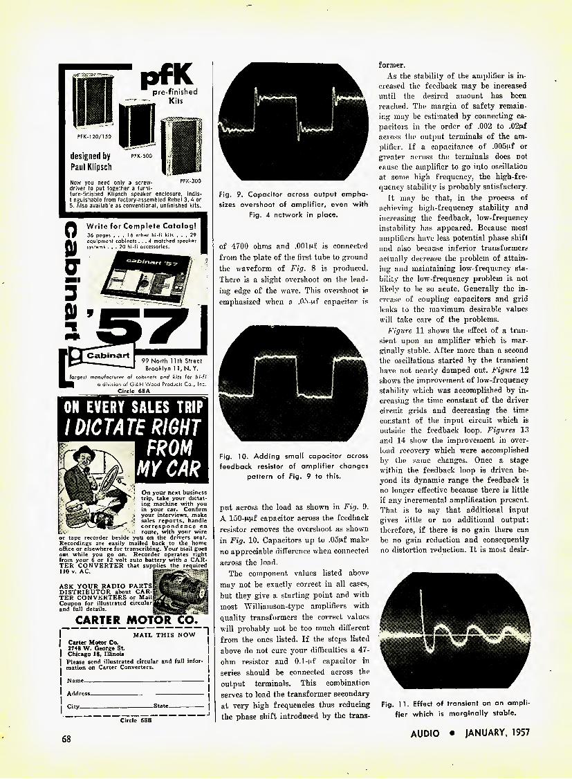
PFK-1 20/150
designed by pfk soo Paul Klipsch
Now you need only a screw- PFK-300 driver to put together a furni- ture-finished Klipsch speaker enclosure, indis- tinguishable from factory-assembled Rebel 3, 4 or 5. Also available as conventional, unfinished kits.
0 Write for Complete Catalog! ■ 36 pages ... 16 other hi-fi kits ... 29 H equipment cabinets ... 4 matched speaker H
■ ll systems ... 20 hi-fi accessories. H
bhk. ^
I 99 North 1 1th Street J Brooklyn 1 1, N. Y.
largest manufacturer of cabinets and kits for hi-fi H a division of GSH Wood Products Co., Inc.
Circle 68A
Circle 68B
Fig. 9. Capacitor across output empha- sizes overshoot of amplifier, even with
Fig. 4 network in place.
of 4700 ohms and .OOluf is connected from the plate of the first tube to ground the waveform of Fig. 8 is produced. There is a slight overshoot on the lead- ing edge of the wave. This overshoot is emphasized when a .05-nf' capacitor is
Fig. 10. Adding small capacitor across feedback resistor of amplifier changes
pattern of Fig. 9 to this.
put across the load as shown in Fig. 9. A 150-M.n.f capacitor across the feedback resistor removes the overshoot as shown in Fig. 10. Capacitors up to .05nf make no appreciable difference when connected across the load.
The component values listed above may not be exactly correct in all cases, but they give a starting point and with most Williamson-type amplifiers with quality transformers the correct values will probably not be too much different from the ones listed. If the steps listed above do not cure your difficulties a 47- ohm resistor and O.l-^f capacitor in series should be connected across the output terminals. This combination serves to load the transformer secondary at very high frequencies thus reducing the phase shift introduced by the trans-
former. As the stability of the amplifier is in-
creased the feedback may be increased until the desired amount has been reached. The margin of safety remain- ing may be estimated by connecting ca- pacitors in the order of .002 to .02nf across the output terminals of the am- plifier. If a capacitance of .005nf or greater across the terminals does not cause the amplifier to go into oscillation at some high frequency, the high-fre- quency stability is probably satisfactory.
It may be that, in the process of achieving high-frequency stability and increasing the feedback, low-frequency instability has appeared. Because most amplifiers have less potential phase shift and also because inferior transformers actually decrease the problem of attain- ing and maintaining low-frequency sta- bility the low-frequency problem is not likely to be so acute. Generally the in- crease of coupling capacitors and grid leaks to the maximum desirable values will take care of the problems.
Figure 11 shows the effect of a tran- sient upon an amplifier which is mar- ginally stable. After more than a second the oscillations started by the transient have not nearly damped out. Figure 12 shows the improvement of low-frequency stability which was accomplished by in- creasing the time constant of the driver circuit grids and decreasing the time constant of the input circuit which is outside the feedback loop. Figures 13 and 14 show the improvement in over- load recovery which were accomplished by the same changes. Once a stage within the feedback loop is driven be- yond its dynamic range the feedback is no longer effective because there is little if any incremental amplification present. That is to say that additional input gives little or no additional output; therefore, if there is no gain there can be no gain reduction and consequently no distortion reduction. It is most desir-
Fig. 11. Effect of transient on an ampli- fier which is marginally stable.
ASK YOUR RADIO DISTRIBUTOR about TER CONVERTERS Coupon for illustrated and full details.
On your next business trip, take your dictat- ing machine with you in your car. Confirm your interviews, make sales reports, handle correspondence en route, with your wire
or tape recorder beside you on the drivers seat. Recordings are easily mailed back to the home office or elsewhere for transcribing. Your mail goes out while you go on. Recorder operates right from your 6 or 12 volt auto battery with a CAR- TER CONVERTER that supplies the required 110 v. AC. ^
CARTER
I MAIL THIS NOW ; I Carter Motor Co. I ' 2748 W. George St. | | Chicago 18, Illinois I Please send illustrated circular and full infor- I | mation on Carter Converters. |
| Name I
I Address^ | City State | 1 J
68 AUDIO • |ANUARY, 1957

able to prevent signals which will drive the amplifier beyond its dynamic range from reaching the amplifier input ter- minals. Despite much talk to the con- trary there is little likelihood that the program material played through a high- fidelity system will include such signals since the program material has already been limited in amplitude and frequency range by the previous systems through which it has been processed. Both disc and tape recording systems have such limitations and, although a frequency modulation transmitter may have excel- lent transient and frequency response, it is likely that most of the program material will have been through some line or program amplifiers which have a response characteristic which is not better than that of the home equipment.
Speaker Distortion
It is possible that some of the program material will be beyond the capabilities of the speaker system to handle. It is most desirable to eliminate these signals before they reach the speaker since a speaker driven beyond its linear limits is a copious source of intermodulation. The limitation of the low-frequency re- sponse of a system can best be accom- plished by installing a high-pass filter between the tone control amplifier and the output amplifier. This filter should cut off at a frequency no lower than 20 cps and preferably higher if the speaker system does not have an excep- tional low-frequency response. Such a filter not only prevents program mate- rial which the speaker cannot handle from reaching the speaker, but it also prevents transients which may result from switching or from interference from overloading the amplifier. It also increases low-frequency stability in cases where the tone-control amplifier gets its plate power from the output amplifier.
Fig. 12. Improvement over pattern of Fig. 1 1 is caused by changing time con-
stant of driver grid circuit.
Fig, 13. Overload recovery of amplifier in condition shown in Fig. 11.
As a final check of stability the ampli- fier should be operated with each of the output tubes removed alternately to see if oscillation ensues. While one of the tubes is removed the amplifier should be driven to saturation at some
Fig. 14. Overload recovery is improved when changes are made as indicated in
Fig. 12.
low frequency to see whether or not little bursts of high-frequency oscillation occur at some time during the low fre- quency cycle. As an acid test on my own amplifiers I repeat this test with tin- load removed, however anyone who does this should bear in mind that he is risk- ing the output transformer should some high-amplitude oscillation result.
Although there are simpler amplifiers which will produce sufficient high-fidelity audio power to fill a living room, the Williamson amplifier or the circuits de- rived from it will give results which cannot easily be excelled. If your Wil- liamson sounds bad it might be a good idea to check on its stability because there must he a great many of them in the condition of the amplifiers from which I made the "before" oscillograms. With just a little work they can be made as good as the amplifiers from which the "after" oscillograms were taken. •
NOW HEAR THIS!
P. O. Box 21 Pearl Beach. Mich. August 15, 1956
Racon Electric Co., Inc. 1261 Broadway New York, N. Y. Gentlemen: Immediately upon arrival of the Racon 15- HW woofer speaker, I mounted it in my sand-filled reflex enclosure which I just completed. I am using the 15-IIW with an 800 cps X-over, in conjunction with a Lorenz 8" midrange and a Lorenz 2%" H.F. cone speaker, X-over at 5000 cps,. and which are mounted on a separate small baffle on top of the L. F. enclosure. As a test recording for my new system, I purposely secured a Richard Purvis Organ recital, 7% ips tape which I found to be very outstanding. I am happy to say the repro- duction is superb. The lowest organ notes are clearly defined, without the lightest sign of distortion or overhang. I have listened to scores of manufactured speaker systems and have yet to hear one which would satisfy me like the one I now have, regardless of price. I will certainly recommend your speaker, whenever the occasion arises.
Yours truly, O. W. Schneider
• ••••••• If your loudspeaker system is suffering from inadequate low frequency response, spend a few minutes listening to the RACON Model 15-HW at your nearest sound distributor. Don't forget to ask him about the unique "HI-C" cone suspension (pat. pending) which provides high compliance, inherent damping and a resonant frequency of 24 cycles. Audio- phile net, $69.50. P.S. RACON, like LORENZ, also manufactures a quality line of mid-range and high frequency speakers.
Write for free literature r HIGH FIDELITY LOUDSPEAKERS ^
R AC O N Q))) jELECTRIC ]
J) COMPANY, INC. 1 n^---—1261 Broodway, New York 1, N.
Export: Joseph Plasencia 401 Broadway, New York, N. Y.
Canada; Dominion Sound Equipments Ltd. 4040 St. Catherine St., West—Montreal 6, Que.
AUDIO • JANUARY, 1957 69
k QUOTE
full-bodied bass . • crisp, clear mid-,;°"9
ter;b',;."
vibrant shimmering ,re,>,® Leadivff Hi-Fi Magazine*. May^
iJfW' TRI-CHANNEL '\>s- HI-FI Sound System
Frankly, only about 12 people who read this ad will be interested enough in the majestic sound reproduction to plunk down $795.00 for the unit. You are one of them . . . only if you sincerely want the truest depth and dimension possible in an audio sys- tem. This is a radical departure from conventional Hi-Fi . . . featur- ing a 3 channel Tone Colour mixer (preamp) feeding 3 separate ampli- fiers and driving 4 speakers — all acoustically matched! Flat fre- quency response from below 25 to above 25,000 cycles. Distortion below recordable measurement. Don't get excited about it unless you can afford the price . Have your sound spe- cialist arrange a demonstration . . . unite today for independent, unbiased performance test reports.
ERCOHA CORPORATION (Electronic Division)
551 Fifth Ave., Dept. 41. New York 17
Circle 70a
IF YOU ARE MOVING Please notify our Circulation Department at least 5 weeks in advance. The Post Office does not forward magazines sent to wrong destinations unless you pay ad- ditional postage, and we can NOT dupli- cate copies sent to you once. To save yourself, us. and the Post Office a head- ache, won't you please cooperate? When notifying us, please give your old address and your new address.
Circulation Department RADIO MAGAZINES, INC.
P. O. Box 629, Mineola, N. Y.
OttdUuisuf, Peofde...
The entire audio industry was saddened by the deaths of three of its members dur- ing- December. Morton Lee, who had been associated with British Industries Cor- poration for over seven years as Sales Manager for a number of its products, died suddenly on December 15 at the age
Morton Lee of 46. He leaves a widow and a daughter. Mr. Dee was widely known throughout the electronics industry as an expert on production development, engineering, and sales, and was well liked and respected by everyone.
Charles Penton Charles F. Fenton, head of the company
bearing his name, treasurer of the Insti- tute of High Fidelity Manufacturers, and also well known in the industry, passed away on December 3 at the age of 51. He is survived by his widow and two chil- dren.
Dieut. Gen. Lewis A. Pick, U.S.A. (Ret), member of the executive committee of ORRadio Industries, Inc., makers of Irish brand recording tape, was the third in- dustry member to pass away in December.
—CLASSIFIED— Rates: ICK per word per insertion for noncommercial advertisements: 25^ per word for commercial adver- tisements. Rates are net, and no discounts will be allowed. Copy must be accompanied by remittance in full, and must reach the New York office by the first of the month preceding the date of issue.
THE AUDIO EXCHANGE has the largest selection of new and fully guaranteed used equipment. Catalog of used equipment on request. Audio Exchange, Dept. AE, 159-19 Hillside Ave.. Jamaica 32. N. Y. AXtel 7-7577 ; 3()7 Mamaroneck Ave., White Plains, N. Y. WH 8-3380. AUDIO EXCHANGE EXCHANGES AUDIO
HI-FIDELITY SPEAKERS REPAIRED Amprite Speaker Service
70 Vesey St., New York 7, N. Y. BA 7-2580
WANT A VERY LOW RESONANCE SPEAKER ?
Ask your dealer to demonstrate the Racon lioa ting-cone. foam-suspension loudspeaker. Or write for literature and prices. Racon Elec- tric Co., 1261 Broadway, New York 1, N. Y.
Long-playing records 20 to 50% discounts ; brand new factory fresh : unplayed ; all labels. Send 200 to Record Discount Club, 1108 Win- bern, Houston 4, Texas.
G-Element BROAD-BAND FM ANTENNAS. All seamless aluminum. $10.95 ppd. Wholesale Supply Co.. Lunenburg 10, Mass.
TRADE-INS FOR SALE: Changers from $6, disc recorders from $13. Write for listings. Custom Electronics, P. O. Box 61G, Camden, N. J.
TEST YOUR RECORDER'S PERFORM- ANCE. Except Dubbings D-110 Test Tape, 98c*. Blank recording tape 3" reel. 3 reels $1*. Free catalog. * Add postage. AMERTEST PRODUCTS CORP., 12S0-B Sheridan Ave., Dept. AD 1, New York 56, N. Y.
Fairchild 199 Disc Recorder, 541-A cutter. Cheap for cash or trade for broadcast audio equipment. Roland Jordan, Jr., WRWJ, Selma, Alabama.
AMPEX 601 RECORDERS : full or half- track. Immediate shipment from stock, $545. Texas Sound Studios, 506 W. Hildebrand, San Antonio, Texas.
PAY MORE . . . WHAT FOR? Unusual sav- ings on all your high fidelity requirements. Write now and save. KEY ELECTRONICS, 120 Liberty St., New York 6, N. Y.
Staggered STEREOPHONIC TAPES, used once, half price. Complete set Cook binaural records, used, make offer. Ronald, 3544 Lee, Cleveland, Ohio.
SELLING OUT! equipment, books, Frank Malley, 210 N. Y.
Free list-—high fidelity parts, instruments, etc. E. 17 St., New York 3,
Circle 70b 70
JOIN IHE
MARCH OF DIMES
januarv
su* ii,ut r" i ™ 1 'I! 1 c
AUDIO • JANUARY, 1957
50 WATTS fromycur WILLIAMSON
New DYNACO A-430
PAT. PENDING
Output transformer and simple circuit modifications let you raise the power of your Williamson-type amplifier to over 50 watts at less than 1% I M distortion. This super-fidelity output transformer will give you double power and double listening pleasure with very low distortion and un-
.Z.V equalled transient bandwidth. Its unique design uses para-coupled windings, the first
at your Elec- hasic advance in quality transformer de- tronic Parts sign since the introduction of interleaved Distributor or windings. Audio Jobber SEE OUR AD ON PACE 50
Write for details of new Di/naeo output transformers, circuits, and conversion data for Williamson Amplifiers.
DYNA COMPANY, Dept. A, 5142 Master St., Phila. 31, Pa.
ENGINEERING MANAGER
Top executive position leading to vice president assignment with na-
tionally known company long established in research, development, and
manufacture in field of miniature electronics, recording, instrumentation, and related products, both commercial and military.
Variety of projects — large and expanding staff of engineers and tech-
nicians — excellent facilities and location.
Requires man of broad engineering background, outstanding technical
abilities in electronic field, creative imagination, and successful record of ad-
ministration and leadership. Age preference 38 to 50. Substantial salary plus
participation in company progress.
Give full personal history and complete detail on fields of experience. Re-
plies confidential. Write Box AE-1-57.
PKOFESSIOXAL III It Ki TO It Y
i|I| HOLLYWOOD ELECTRONICS j 1 DISTRIBUTORS OF HI-FI COMPONENTS
E X c LUS IVEI V
7460 Melrose Ave- Los Angeles 46,Calif • WEbster 3-8208 Circle 71a
AUD-O-FILE nlin ly ni'W mi-thod lot filmq fina- n-cotdl NO INDfcXES! NO JACKETS! NO SLEEVES! NO ALBUMS!
ROBINS INDUSTRIES CORP ^oysid* 61, N. Y.
Circle 71b
HIGH-FIDELITY HOUSE Most complete itock of Audio
components in the West Phone: RYan 1-8171
536 S. Fair Oaks, Pasadena 1, Calif.
Circle 71c
Circle 71d
Moi&i,..
IHFM SETS UP NEW COMMITTEES. Establishment of a Credit Committee and a Catalog Committee of the Institute 01 Higrh Pidelity Manufacturers has been an- nounced by George Silber, president. The Credit Committee will study methods for establishing a credit information service for members of the Institute. The advis- ability of a syndicated industry-wide cat- alog will be considered by the Catalog Committee. Ben 1j. Arons, Fisher Radio Corporation is chairman of the Credit Committee, which also includes: Ben Was- serman, University Loudspeakers, Inc.; Franklin Hoffman, British Industries Corp.; Malcom Bow, Acoustic Research, Inc., and T. J. Nicholson, General Electric Company.
The Catalog Committee is headed by Milton Thalberg, Audiogersh Corporation. Other members of the committee are: Henry A. Schober, Audio Magazine; H. S. Morris, Altec Lansing Corporation; Claire Eddings, Audiocom, Inc., and Sidney Frey, Dauntless International.
Membership in the Institute now in- cludes 74 companies with the recent con- fumation of Duotone Company, Keyport, N. J., and the Recoton Corp., Bong Island City, N. Y., as general members.
GRAY HI-FI BEMO SYSTEM. A com- plete high fidelity demonstration system especially designed for use by dealers has been introduced by Gray Research and De- velopment Company. Available to dealers on a liberal long-term rental purchase plan, the system consists of a Gray vis- cous-damped tone arm, a precision turn- table, amplifier and speaker. Increases in record sales of up to 600 per cent are be- ing reported by dealers using the system to illustrate the full potential of modern hi-fi records.
CANADA High Fidelity Equipment
Cemplet* Lines • Cemplete Berrlec Hl-n Becorda — Componeat*
and Aeeanorle*
ftLECTRC-VoiCE ^ SOUND SYSTEMS
141 DUN OAS ST. WB5T. TORONTO, CANADA.
Circle 71e
LETTERS {frnm page 57)
Sir; I read with considerable interest Mr.
A. A. Janszen's comments on Mr. Briggs earlier letter. I would also like to acknowl- edge the kick-ou-the-pants he gives me over my enthusiastic reports on the full-range electrostatic speaker in the Hi-Fi Year Hook and in Becorcl News. I shall never live that down, but I am now completely unrepentant since it has provoked Mr. Briggs into designing and producing a new loudspeaker (the Si'B/3) to prove I was wrong. This he has very nearly done, since I can now enjoy practically all of the hoped-for advantages of the full-range elec- trostsatic. These are, principally: the very smooth over-all response; large sound- source area giving the illusion of a very clear view of the reproduced item : doublet sound source (at the lower frequencies anyway) giving less listening-room colour- ation. All this with no amplifier stability problems either. Well, they say it's an ill wind that blows nobody any good.
I think Mr. Briggs has forgiven me, we are on speaking terms again. I hope so, anyway, as I want to borrow a second speaker for stereophonic reproduction!
Ealph West, Northern Polytechnic, London, England
the finest in Hi-Fi
featuring Eleclftctfyrcz.^ HIGH FIDELITY COMPONENTS
SOUND MSS^Sm CORPORATION! HDOSIS^ 820 W. Olympic Blvd. • LA. 15. Calif. - Rl "'■0271
Circle 71f
KLeeNeeDLE
ROBINS INDUSTRIES CORP. Bayide 61, N. Y.
CHANGER NEEDLE BRUSH
KLeeNeeDLE automatically keeps record changer needles clean. It is designed to remove the familiar "dust-blob" from under the needle point. At Your
Dealer
AUDIO • 1ANUARY, 1957 71
SAVE
25%
This is our
CROUP SUBSCRIPTION PLAN
Now you, your friends and co-workers can save $1.00 on each subscription to AUDIO. If you send 6 or more sub- scriptions tor the U.S., Possessions and Canada, they will cost each subscriber $3.00 each, Va less than the regular one year subscription price. Present subscriptions may be renewed or ex- tended as part of a group. Remittance to accompany orders.
AUDIO is still the only publication devoted entirely to
• Audio • Broadcasting equipment • Acoustics • Home music systems • Recording • PA systems • Record Revues
(Please print)
Name Address
□ New □ Renewal
Name Address
□ New □ Renewal
Name Address
□ New □ Renewal
Name Address
□ New □ Renewal
Name Address
□ New □ Renewal
Name Address
□ New □ Renewal
U. S., Possessions, and Canada only
RADIO MAGAZINES, INC. P. 0. Box 629, Mineola, N. Y.
ADVERTISING
INDEX
Acoustic Research, Inc 39. 60 Allied Radio Corporation 64 A M I Incorporated 34 Amperex Electronic Corporation 54 Ampex Corporation 49 Audak Co 48 Audio Fidelity Recordings 43, 45 Audiogersh Corporation 44
Bell Telephone Laboratories 14 Bogen, David Company, Inc 36, 37 Bradford & Company 62 British Industries Corporation facing p. 1, 3, 64
Cabinart 68 Carter Motor Co 68 Classified 70 Collaro Record Changers Cov. Ill
Dyna Company 50, 70 Electro-Sonic Laboratories 63 Electro-Voice Inc Cov. IV, 2 Electro-Voice Sound Systems 71 Ercona Corporation 70, 72 Fairchild Recording Equipment Co 6 Fisher Radio Corporation 46, 47 Frukuin Electric Works, Ltd 52 General Electric Company 41 Goodmans Industries Ltd 5 Harman Kardon, Inc 31 Harvey Radio, Inc 59 Heath Co 10, 11 High Fidelity House 71 Hollywood Electronics 71 JansZen Speakers (Neshaminy Electronic
Corp.) 57 Jensen Manufacturing Company 29
Kierulff Sound Corporation 71 Lansing, James B.t Sound, Inc 33 Leonard Radio, Inc 60 Marantz Company 63 Mullard Overseas, Ltd 9
North American Philips Co.. Inc 8
Orradio Industries, Inc Cov. II Orthosonic Instruments, Inc 67 Pickering & Company 13 Pilot Radio Corporation 7 Precision Electronics, Inc 54 Professional Directory 71
Racon Electric Co., Inc 69 Rauland-Borg Corporation 66 Rego Hi Fi Shows 65 Rek-O-Kut Company 51 Robins Industries Corporation 71 Sams, Howard W. & Co., Inc 56 Scott, H. H., Inc 53 Shure Brothers, Inc 1
Tung-Sol Electric, Inc 4
University Loudspeakers, Inc 55, 66 Weathers . Industries 61, 65
If You're a Connoisseur... you'll want a
TURNTABLE
mo00
Compare the Connoisseur with any turntable and you'll marvel at its performance. Non-magnetic, 12" lathe-turned table; precision ground spindle; phosphor bronze turntable bearing.±2% variation provided for all 3 speeds; hysteresis motor.
TURNTABLE: Rumble—better than 50 db down; Wow—less than 0.15% of rated speed; Dimensions: 13%xl5%". PICKUP: Frequency Response — 20- 20,000 cps ±2 db at 33% rpm; Effec- tive Mass—4 mg; Impedance—400 ohms at 1000 cps.
"Dynabalanced" tone arm with Mark II super-lightweight pickup w/diamond stylus $49.50 • • • w/sap- phire stylus $34.50.
CRCOMA CORPORATION (Electronic Divis'on)
551 Fifth Ave., Dept. (E3B « New York 17 In Canada, write Astral Electric Comjki»n
Limited, 44 Danforth Road, Toronto !■>
Cancer can't strike me, I'm hiding.
k Cancer? The American Cancer Society says that too many people die of it, needlessly ! That's why I have an annual medical checkup hoivever well I feel. I knoiv the seven danger signals. And ivhen I want sound information, I get it from my Unit of the
AMERICAN CANCER SOCIETY
72 AUDIO • JANUARY. 1957

SIMPLE AS
To make it just as easy as possible for AUDIO'S readers to subscribe, order books, get further information about the new products and the new literature mentioned in the pages of the magazine, or ro get catalog sheets and brochures describing articles advertised, we provide herewith three cards. We know that many readers are loath to cut coupons from the pages of their favorite magazine because they have told us so. And we know that many time'1 one would like to have complete and thorough data about something he sees in these pages, yet he considers it too much trouble to hunt up paper and envelope—not to mention the stamp—and write a long letter detailing what he wants to know. This is just as simple as we know how to make it with the exception of stenciling each subscriber's name and address on each of the postcards—an operation which would be highly impractical from the printing standpoint. But from now on, when you want more information about something you have seen advertised or mentioned in AUDIO you need only indicate it on the appropriate card, print your name and address, and drop it in the nearest postbox. We pay the postage, and it goes without saying that we wouldn't include these cards if we didn't welcome your use of them. And, for the first time, you can enter your subscription without sending a penny with your order—we'll bill you later. For books, we'll have to ask for the money in advance, but only for books.
Readers have told us that they often want to know more about some of the items men- tioned in the New Products and New Litera- ture pages of the magazine, but that they do not want to take the time and effort to write to each one of the sources individually to get all the information they need. As a matter of fact, in an average issue there are usually ten items in the New Literature column, and between ten and fifteen on the New Products pages. It is conceivable that the average reader might want infor- mation on at least ten of these items, since they are selected with the interests of most of AUDIO'S readers in mind. Thus one would have to have ten envelopes, ten sheets of paper, and ten three cent stamps, together with the need for writing the ten letters and inscribing each with name and address. We do it all for you, assuming that you are willing to circle the items about which more
information is desired and to write your name and address once. We will forward your inquiries to the organization involved, and you will receive the data you want with only one inquiry Isn't that as simple as A B C?
In just the same way you can get more in- formation about any product that is advertised in the pages of AUDIO. Note the page on which the advertisement appears and circle it on the back side of this card. When there are two or more ads on the same page, the page number is followed by a letter, and the designation appears under each individual advertisement. Write your name and address clearly—someone has to decipher it—and it is a good idea to mark the card for all the information you want the first time, for there is only one card in each copy of the maga- zine. Of course, you could subscribe to two copies
nn * o UJ X o M
ONEY
OR
DER
□ □
-I -J is > O < 2 Q. UJ
o 5
> D <
z o H 03 Z O o OJ c h- a.
a: U i/i ON CO 3 rsi l/l VD >- X o 2 CG oc UJ H d
Z Z UJ
CL UJ UJ 5 l/> 6 UJ -J < UJ 3
H Z -J a.
< s
O to
,□3
ini UJ >- CVJ
O
z o N
5 < z
o Q < O
CUT APART ON DASHED LINES
O
u >-1 _| 3
VJ £
to
o cs o X o
CO
d
CL
_2 o 0) c

3 (D o_ Q; 00
o X
o K) <5
CO
Z
O to 3, t/>
ipo
o_
■£ ?0 O
>>>>>>>> i i i i i i i i 00\JO(-ri^.C0h0 —
>>>>>>>> i i I i I I I I o en 4^ co ro — o
0 O O 1 i i co ro > > > > O
Z o
x -
cr > — c
!§
Q cr -o ?S" Of -f (D o- S «/> ir ^ Q. Q. 3 < 0) 5 -4- c
> o a z > 5
•o 00 00
n >
o^cn ^ CO — NO ' 4^ QO \l u >
CONJ—'OO^OOOVJ cr o
O o Ln <_n — O NO Ui Ui Oi Ln — O cn 4^ -N r- cr q
0s o» 0s o o o ^o o oi -N co co ro c^i o cr a cr q \i
xi vj o o o o o O O O CO 00 \1 o cr o cr o o-
\i \J \i \i \J CO -^0 Q_ n or o
(t> zr Q_ (D
(I 3 n Q
^s- ■U o o C CO ft =f- -*> o o 3- D_ a> o c_ Q- Q -* i 1 Q 3
ui O c — D-
N o z
BOOK ORDER
Please send me the books checked below, postage paid. I enclose check [J money order Q for $ in full payment.
Tape Recorders and Tape Recording
Harold D. Weiler □ Paper Cover, $2.95 □ Board Cover, $3.95
□ the 3rd Audio Anthology Board cover, $3.50
□ the 3rd Audio Anthology Paper cover, $2.50.
□ Electronic Musical Instruments $7.50 in U. S. (All others $8.00)
□ AUDIO—Bound Volumes— 1955 issues $ 10.00 (In U. S. only)
To start receiving Audio monthly without
any effort on your part to locate one
on the newsstands or at your jobber's,
mark the appropriate boxes with crosses,
tear out the card, and drop it into a handy postbox. If you are one of those who always pays in advance, we will accept your check or money order—we do not recommend cash to be sent through the mails—enclose the card in
an envelope, and mail. This will cost
you an extra three cents, so if you wait
until we send you a bill, we'll enclose a
business reply envelope for your con- venience. We try to make it as easy for you as we know how.
NAME.
ADDRESS.
CITY. . ZONE STATE-
NOW IT IS EASIER — ONLY ONE CARD
is necessary to get more information about any New Product or
New Literature item, or about any product advertised in these pages.
At the end of each item of New Litera- ture, New Products, or Equipment Reports you will notice a letter and a number—the letter indicates the month and the number indicates which item it is. All you have to do to get full information about the product or to get the literature described is to circle the appropriate number, add your name and address and mail it to us. We'll do the rest, and you may be sure that we'll be prompt because we are just as anxious for your inquiries to get to their destination as you are—and besides, we don't have room enough around the office to accumulate a lot of cards. Circle one item, if you wish, or all of them—we'll carry on from there. This whole system breaks down if there is a charge for the New Literature described, so if you can suggest any improvements in this service, we would appreciate hearing about them.
To get more information about the prod- ucts that are advertised in each issue of AUDIO—use the new card at the left. Fill in your name and address clearly and circle the number of the page on which the advertisement appears. When there are two or more ads on a page, each one has under it a notation such as Circle 23a. Circle 48b, or Circle 76c and the same numbers appear on the card. Numbers C-2, C-3, and C-4 refer to the covers— C-2 is the inside front cover, C-3 the inside back cover, and C-4 is the out- side back cover. SB is "The Sounding Board."
The only way to derive any benefit from this service is to use the card for all the information you want. We think you will find this new system more convenient and that you will use it more and more.
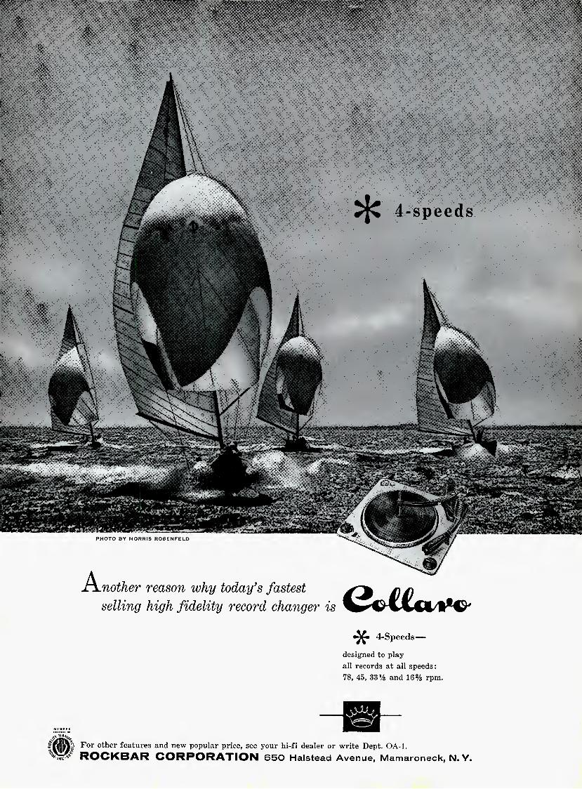
PHOTO BY MORRIS ROSENFELD
A^nother reason why today's fastest
selling high fidelity record changer is
4-speeds
4-Spee(ls—
designed to play- all records at all speeds: 78, 45, 33 % and 16% rpm.
For other features and new popular price, see your hi-fi dealer or write Dept. OA-1, ROCKBAR CORPORATION 650 Halstead Avenue, Mamaroneck, N. Y.
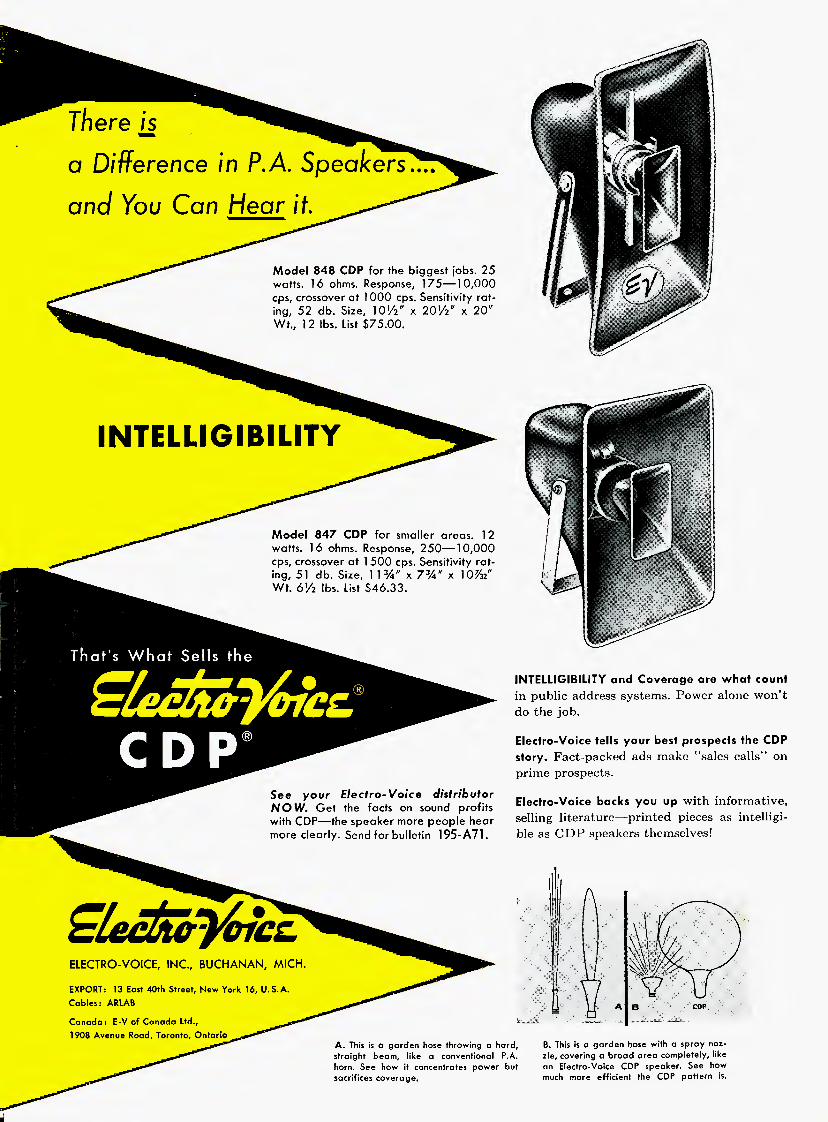
a Difference in P.A. Speakers.,,,
and You Can Hear if.
Model 848 CDP for the biggest jobs. 25 watts. 16 ohms. Response, 175—10,000 cps, crossover at 1000 cps. Sensitivity rat- ing, 52 db. Size, lO'/z" x 201/2" x 20" Wt., 12 lbs. List $75.00.
INTELLIGIBILITY
Model 847 CDP for smaller areas. 12 watts. 16 ohms. Response, 250—10,000 cps, crossover at 1 500 cps. Sensitivity rat- ing, 51 db. Size, 1 1 %" x 73A" x 10^2" Wt. 61/2 lbs. List $46.33.
See your Electro-Voice distributor NOW. Get the facts on sound profits with CDP—the speaker more people hear more clearly. Send for bulletin 195-A71.
INTELLIGIBILITY and Coverage are what count in public address systems. Power alone won't do the job.
Elecfro-Voice tells your best prospects the CDP story. Fact-packed ads make "sales calls" on prime prospects.
Electro-Voice backs you up with informative, selling literature—printed pieces as intelligi- ble as CDP speakers themselves!
Slectiicj6tcc
ELECTRO-VOICE, INC., BUCHANAN, MICH.
EXPORT: 13 East 40th Street, New York 16, U.S.A. Cables: ARLAB
Canada: E-V of Canada Ltd., 1908 Avenue Road, Toronto, Ontario
A. This is a garden hose throwing a hard, straight beam, like a conventional P.A. horn. See how it concentrates power but sacrifices coverage.
A
B. This is a garden hose with a spray noz- zle, covering a broad area completely, like an Electro-Voice CDP speaker. See how much more efficient the CDP pattern is.